Tânia Sofia dos Santos Vieira Mestre em Ciências Biomédicas Development of a new nanostructured scaffold for neural stem/progenitor cell transplantation Dissertação para a obtenção do grau de Doutor em Bioengineering Systems – MIT Portugal Program Orientador: Dr Célia Henriques, Profª auxiliar, FCT-UNL Co-orientador: Dr João Paulo Borges, Prof auxiliar, FCT-UNL Co-orientador: Dr Ana Sofia Falcão, Pos-doc, CEDOC Júri: Presidente: Prof.Doutor Luís Paulo da Silva Nieto Marques Rebelo Arguentes: Profª. Doutora Maria Helena Mendes Gil Doutor Hugo Agostinho Machado Fernandes Vogais: Prof. Doutor António Alfredo Coelho Jacinto Profª. Doutora Maria Helena Figueiredo Godinho Prof. Doutor Frederico Castelo Ferreira Prof. Doutora Célia Maria Reis Henriques Doutora Ana Paula Gomes Moreira Pêgo Outubro de 2017
Transcript
Tânia Sofia dos Santos Vieira
Mestre em Ciências Biomédicas
Development of a new nanostructured scaffold for neural stem/progenitor cell
transplantation
Dissertação para a obtenção do grau de Doutor em Bioengineering Systems – MIT Portugal Program
Orientador: Dr Célia Henriques, Profª auxiliar, FCT-UNL Co-orientador: Dr João Paulo Borges, Prof auxiliar, FCT-UNL Co-orientador: Dr Ana Sofia Falcão, Pos-doc, CEDOC
Júri:
Presidente: Prof.Doutor Luís Paulo da Silva Nieto Marques Rebelo Arguentes: Profª. Doutora Maria Helena Mendes Gil Doutor Hugo Agostinho Machado Fernandes Vogais: Prof. Doutor António Alfredo Coelho Jacinto Profª. Doutora Maria Helena Figueiredo Godinho Prof. Doutor Frederico Castelo Ferreira Prof. Doutora Célia Maria Reis Henriques Doutora Ana Paula Gomes Moreira Pêgo
Outubro de 2017
ii
iii
Development of a new nanostructured scaffold for neural stem/progenitor cell transplantation
α Constant dependent on the solution (solute-solvent system) and temperature
xxiv
β Full width at half maximum
Y Young modulus
ΔHm Enthalpy of fusion
Ɛr Elongation at break
[ƞ] Intrinsic viscosity,
θ Diffraction angle
Ia Area of the diffraction peaks resulting from the amorphous reflections
Ic Area of the diffraction peaks resulting from the crystalline reflections
K Constant dependent on the solution (solute-solvent system) and temperature
λ Wavelength
Mv Viscosimetric molecular weight
σ600. Tensile stress at 600% strain
ρ Density
τ Crystallite size
Tg Glass transition temperature
Thard Degradation temperatures of soft segments
Tm Melting temperature
Tsoft Degradation temperatures of soft segments
W1 Specific gravity bottle weight filled with water
W2 Specific gravity bottle weight with water and scaffold
W3 Specific gravity bottle weight after removal of water-saturated matrix from W2
Wc,x Crystalline degree
Wi Initial mass
Wk Remaining mass
Ws Scaffold weight
xxv
xxvi
Chapter 1
Introduction
Chapter 1
2
1. Introduction
Spinal cord injury (SCI), either traumatic or non-traumatic in origin, represent a major health
problem affecting not only the patient but also their family and the community. After the injury,
loss of nervous tissue and consequently loss of motor and sensory function often produce
permanent disabilities such as respiratory failure, pressure sores and autonomic dysreflexia,
resulting in complete or partial paralysis (Thuret, Moon et al. 2006; Madigan, McMahon et al.
2009). Worldwide, it is estimated that 2.5 million people live with SCI, with more than 130,000
new SCI reported each year (International Campaign for Cures of Spinal Cord Injury Paralysis,
website: http://www.campaignforcure.org/). The main causes of SCI are road traffic accidents,
falls, violence and sports activities (Injury 2005), which affects mainly young people with ages
between 15 and 29 years (Van den Berg, Castellote et al. 2010). Less than 1% of people who
suffered from some type of SCI can recover complete neurological function (Injury 2005).
Unfortunately, there are no actual clinical treatment for this disability. Pain reliefs and
surgical decompression are the only procedures realized in clinics, depending on the type of
injury, but they are far from ideal to promote the functional regeneration. The transplantation of
functional stem cells, mainly neural stem cells (NSCs), to the injury site can lead to minimal
improvements at the sensory-motor functions (Tsukamoto, Uchida et al. 2013). However, a few
cells survive in the inhospitable injury environment and their differentiation is not controlled.
Tissue engineering has been working out in a new therapeutic regenerative approach for the
treatment of damaged or missing tissues or organs. In this approach, engineered scaffolds are
aimed at creating an appropriate environment to support endogenous cell regrowth and a possible
cell transplantation from exogenous sources. Recent studies have point out the implantation of
scaffolds as a vehicle for NSCs transplantation as a promising therapeutic strategy to fill in the
injury site and promote the spinal cord regeneration (Saglam, Perets et al. 2013; Li, Liu et al.
2016). However, the role of the scaffolds is far beyond that. A scaffold may provide chemical cues
(type of polymer and/or functionalization) (Ren, Zhang et al. 2009), mechanical properties (Leipzig
and Shoichet 2009) and topographical cues (nano and micro scale topographies)
(Kerativitayanan, Carrow et al. 2015) to influence stem cell behavior. Therefore, gather in a
scaffold all the characteristics that act in synergy to support the differentiation of NSCs in
functional neurons that extent axons over significant distances and form synapses with the host
neurons around the injury site is still a challenge.
The goal of this project was to develop a tissue engineering approach to produce an
electrospun mat to guide the NSCs. The stem cells respond to the substrate chemical cues as
well as to the micro and nanotopography, similar to the extracellular matrix (ECM), which
determine their fate. With this idea, three main tasks were performed: (1) develop new
biocompatible and biodegradable polyurethanes, (2) process those polyurethanes with the
electrospinning technique to get fibrous mats, and (3) evaluate the effect of the chemical and
topographic cues on the NSPCs.
Chapter 1
3
In chapter 2 the SCI problem is described and an overview of the polymers used in tissue
engineering scaffolds for spinal cord repair are exposed. The benefits of use scaffolds seeded
with NSCs were also detailed. Finally, the effect of the scaffolds topographic and chemical cues
were also addressed.
Different techniques were used to create scaffolds with a structure similar to the ECM:
phase separation, self-assembly peptide nanofibers and electrospinning. From those,
electrospinning has been investigated in the construction of conduits that not only fill in the injury
and bridge the lesion site but also contain the topographical signals essential to provide contact
guidance to host cells infiltration and axonal outgrowth (Liu, Houle et al. 2012). The easy control
over the fiber alignment and diameter as well as their functionalization, make the fibrous
substrates suitable to support NSCs (Lim, Liu et al. 2010). The polyurethanes (PUs) are polymers
whose their properties can be easily tunable. Therefore, PUs can be designed to have customized
chemistry and mechanical properties, resulting in promising biomaterials for a wide range of tissue
engineering applications (Guelcher 2008). Electrospun mats from designed PUs are promising
substrates for stem cell support in order to promote blood vessels replacement (Wang, Li et al.
2013) and tendon/ligament regeneration (Cardwell, Dahlgren et al. 2012). However, for spinal
cord, there are no reports designing and processing through electrospinning a tunable PU to get
mats that support and induce the differentiation of NSCs.
To overcome this gap, in chapter 3 is described the synthesis of PUs extended with
dimetlylol proprionic acid (DMPA), DMPA and chitosan (CS) and CS, which were characterized
with spectroscopic techniques and thermal analysis. CS is widely used in biomedical applications
due to its biocompatibility, biodegradability and antimicrobial, antimicrobial, antioxidant and
hemostatic properties (Dash, Chiellini et al. 2011). In neural regeneration, CS has been explored
as a suitable biomaterial for neural differentiation (Du, Tan et al. 2014). It is also described the
optimization of the electrospinning process in order to get mats from the synthetized PUs with
random and aligned morphology. Their morphology, mechanical properties, degradation profile,
wettability and cytotoxicity were evaluated. The mats were also seeded with caucasian foetal
foreskin fibroblasts (HFFF2) cells and the adhesion and proliferation of the cells on the mats was
evaluated.
In the chapter 4, and similarly to the chapter 3, is described the synthesis and
characterization of the PUs extended with gelatin. The gelatin quantity was adjusted to render a
polymer suitable for electrospinning. Gelatin is a biocompatible and biodegradable natural
polymer derived from the hydrolysis and denaturation of collagen, with motifs for cell adhesion
and prolileration (Kang, Tabata et al. 1999). However, gelatin is water soluble and their use as
scaffold requires an additional crosslinking step. The crosslinking agents are toxic and can left
toxic residues in the gelatin scaffolds, which can also impair their structure (Amadori, Torricelli et
al. 2015). The incorporation of the gelatin in the PU structure prevent that. The electrospinning
parameters for the synthetized PUs were optimized. The resulting mats with random and aligned
Chapter 1
4
morphology were characterized according to mechanical properties, degradation profile,
wettability and cytotoxicity. The adhesion and proliferation of HFFF2 fibroblasts in the mats was
also studied.
In the chapter 5, the ability of the mats from PUs extended with either chitosan or gelatin
to support human mesenchymal stem cells (MSCs) and NSCs is evaluated. Mats were seeded
with human MSCs and adhesion and proliferation assay as well as fluorescent staining was
performed to evaluate the viability of those cells on the mats. Human NSCs were also seeded
on the mats and their proliferation was evaluated. In addition, the ability of the cells to differentiate
in neurons on the mats, without additional biomolecules, was evaluated by immnufluorescent
analysis.
Finally, the conclusions of this study are described in chapter 6. The results demonstrate
the feasibility of the electrospun mats to support human mesenchymal and neural stem cells.
Further research on the field is also described.
References
Amadori, S., P. Torricelli, et al. (2015). "Effect of sterilization and crosslinking on gelatin films." Journal of Materials Science: Materials in Medicine 26(2): 1-9.
Cardwell, R. D., L. A. Dahlgren, et al. (2012). "Electrospun fibre diameter, not alignment, affects mesenchymal stem cell differentiation into the tendon/ligament lineage." Journal of tissue engineering and regenerative medicine 8(12): 937–945.
Dash, M., F. Chiellini, et al. (2011). "Chitosan—A versatile semi-synthetic polymer in biomedical applications." Progress in polymer science 36(8): 981-1014.
Du, J., E. Tan, et al. (2014). "Comparative evaluation of chitosan, cellulose acetate, and polyethersulfone nanofiber scaffolds for neural differentiation." Carbohydrate polymers 99: 483-490.
Guelcher, S. A. (2008). "Biodegradable polyurethanes: synthesis and applications in regenerative medicine." Tissue Engineering Part B: Reviews 14(1): 3-17.
National Spinal Cord Injury Statistical Center. (2005). "Spinal Cord Ijury. Facts and Figures at a Glance." The Journal of Spinal Cord Medicine 28(4): 379:380.
Kang, H.-W., Y. Tabata, et al. (1999). "Fabrication of porous gelatin scaffolds for tissue engineering." Biomaterials 20(14): 1339-1344.
Kerativitayanan, P., J. K. Carrow, et al. (2015). "Nanomaterials for engineering stem cell responses." Advanced healthcare materials 4(11): 1600-1627.
Leipzig, N. D. and M. S. Shoichet (2009). "The effect of substrate stiffness on adult neural stem cell behavior." Biomaterials 30(36): 6867-6878.
Li, X., S. Liu, et al. (2016). "Training Neural Stem Cells on Functional Collagen Scaffolds for Severe Spinal Cord Injury Repair." Advanced Functional Materials 26(32): 5835-5847.
Lim, S. H., X. Y. Liu, et al. (2010). "The effect of nanofiber-guided cell alignment on the preferential differentiation of neural stem cells." Biomaterials 31(34): 9031-9039.
Liu, T., J. D. Houle, et al. (2012). "Nanofibrous collagen nerve conduits for spinal cord repair." Tissue Engineering Part A 18(9-10): 1057-1066.
Chapter 1
5
Madigan, N. N., S. McMahon, et al. (2009). "Current tissue engineering and novel therapeutic approaches to axonal regeneration following spinal cord injury using polymer scaffolds." Respiratory physiology & neurobiology 169(2): 183-199.
Ren, Y.-J., H. Zhang, et al. (2009). "In vitro behavior of neural stem cells in response to different chemical functional groups." Biomaterials 30(6): 1036-1044.
Saglam, A., A. Perets, et al. (2013). "Angioneural crosstalk in scaffolds with oriented microchannels for regenerative spinal cord injury repair." Journal of Molecular Neuroscience 49(2): 334-346.
Thuret, S., L. D. Moon, et al. (2006). "Therapeutic interventions after spinal cord injury." Nature Reviews Neuroscience 7(8): 628-643.
Tsukamoto, A., N. Uchida, et al. (2013). "Clinical translation of human neural stem cells." Stem Cell Res Ther 4(4): 102.
Van den Berg, M., J. Castellote, et al. (2010). "Incidence of spinal cord injury worldwide: a systematic review." Neuroepidemiology 34(3): 184-192.
Wang, F., Z. Li, et al. (2013). "Fabrication of mesenchymal stem cells-integrated vascular constructs mimicking multiple properties of the native blood vessels." Journal of Biomaterials Science, Polymer Edition 24(7): 769-783.
Chapter 1
6
Chapter 2
Literature Review
Chapter 2
8
2. Literature Review
2.1 Spinal Cord Injury
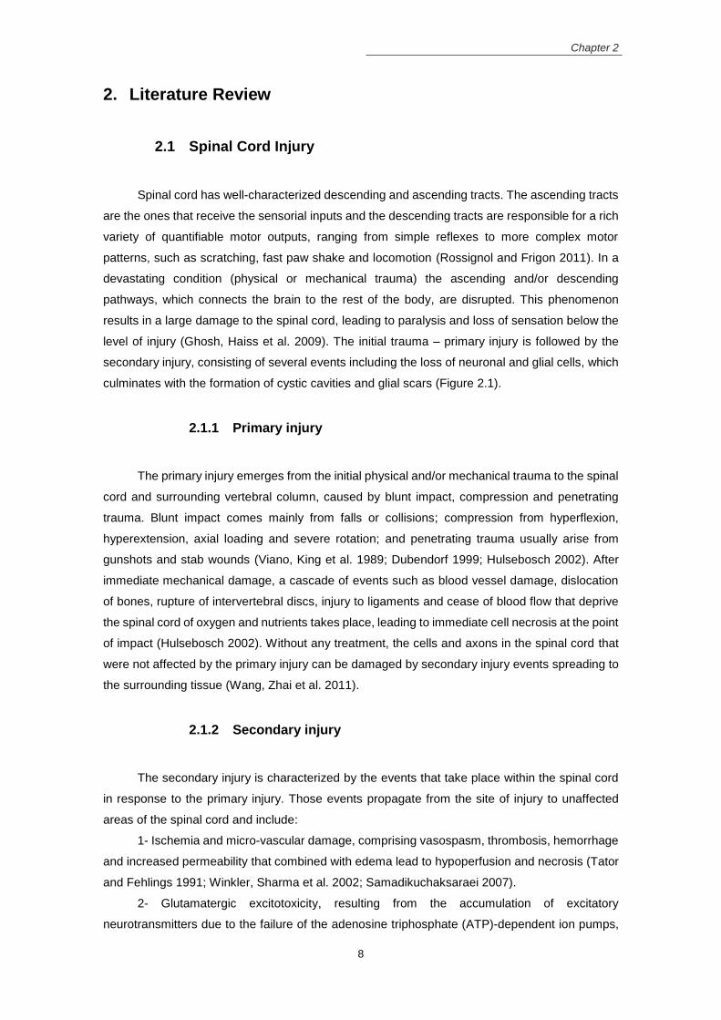
Spinal cord has well-characterized descending and ascending tracts. The ascending tracts
are the ones that receive the sensorial inputs and the descending tracts are responsible for a rich
variety of quantifiable motor outputs, ranging from simple reflexes to more complex motor
patterns, such as scratching, fast paw shake and locomotion (Rossignol and Frigon 2011). In a
devastating condition (physical or mechanical trauma) the ascending and/or descending
pathways, which connects the brain to the rest of the body, are disrupted. This phenomenon
results in a large damage to the spinal cord, leading to paralysis and loss of sensation below the
level of injury (Ghosh, Haiss et al. 2009). The initial trauma – primary injury is followed by the
secondary injury, consisting of several events including the loss of neuronal and glial cells, which
culminates with the formation of cystic cavities and glial scars (Figure 2.1).
2.1.1 Primary injury
The primary injury emerges from the initial physical and/or mechanical trauma to the spinal
cord and surrounding vertebral column, caused by blunt impact, compression and penetrating
trauma. Blunt impact comes mainly from falls or collisions; compression from hyperflexion,
hyperextension, axial loading and severe rotation; and penetrating trauma usually arise from
gunshots and stab wounds (Viano, King et al. 1989; Dubendorf 1999; Hulsebosch 2002). After
immediate mechanical damage, a cascade of events such as blood vessel damage, dislocation
of bones, rupture of intervertebral discs, injury to ligaments and cease of blood flow that deprive
the spinal cord of oxygen and nutrients takes place, leading to immediate cell necrosis at the point
of impact (Hulsebosch 2002). Without any treatment, the cells and axons in the spinal cord that
were not affected by the primary injury can be damaged by secondary injury events spreading to
the surrounding tissue (Wang, Zhai et al. 2011).
2.1.2 Secondary injury
The secondary injury is characterized by the events that take place within the spinal cord
in response to the primary injury. Those events propagate from the site of injury to unaffected
areas of the spinal cord and include:
1- Ischemia and micro-vascular damage, comprising vasospasm, thrombosis, hemorrhage
and increased permeability that combined with edema lead to hypoperfusion and necrosis (Tator
and Fehlings 1991; Winkler, Sharma et al. 2002; Samadikuchaksaraei 2007).
2- Glutamatergic excitotoxicity, resulting from the accumulation of excitatory
neurotransmitters due to the failure of the adenosine triphosphate (ATP)-dependent ion pumps,
Chapter 2
9
conducting to the depolarization of the neuronal membrane potential (McDonald and Sadowsky
2002; Park, Velumian et al. 2004).
3- Oxidative stress, resulting from free radical formation and lipid peroxidation that can
attack membranes and other cell components, disturbing unaffected neurons and
oligodendrocytes (Braughler and Hall 1989; McDonald and Sadowsky 2002).
4- Inflammation, recruitment and activation of inflammatory cells associated with secretion
of cytokines, which contribute to further tissue damage (Dusart and Schwab 1994; Takami,
Oudega et al. 2002).
5- Loss of ionic intracellular balance, increase of the opioids at the injury site, depletion of
energy metabolites, conducting to an anaerobic metabolism, an increase of lactate
dehydrogenase (LDH) activity and an activation of calpains and caspases, culminating in cellular
apoptosis (Samadikuchaksaraei 2007).
After days to weeks from the injury, a fluid filled cystic cavity is formed due to the removal
of injured neurons, their axons and necrotic debris. The cyst is expanded to adjacent spinal cord
areas, increasing the cell dead and loss of neuronal function, mainly the dead of oligodendrocytes
that lead to malfunction and degeneration of the intact axons.
Finally, due to the absence of phagocytic macrophages, a scar is formed not only to
promote wound healing but also to limit the spreading of the injury to unaffected areas. In the
central nervous system (CNS), two types of scar tissue were identified, the fibrous scar in the
core and the glial scar in the surrounding parenchyma. The glial scar is constituted by reactive
astrocytes from self-duplication, oligodendrocyte progenitors and astrocytes derived from the
ependymal cells (presented at the central canal of the spinal cord with the ability of neural stem
cells), which are activated after a lesion (Sabelström, Stenudd et al. 2014). On the other hand,
the fibrotic/inflammatory scar is formed from collagen IV, which result in a meshwork basement
membrane where other ECM compounds and inhibitory molecules can bind. It also has
perivascular fibroblasts that deposit on the basal lamina and form a barrier between the lesion
core and the penumbra (Soderblom, Luo et al. 2013).
Chapter 2
10
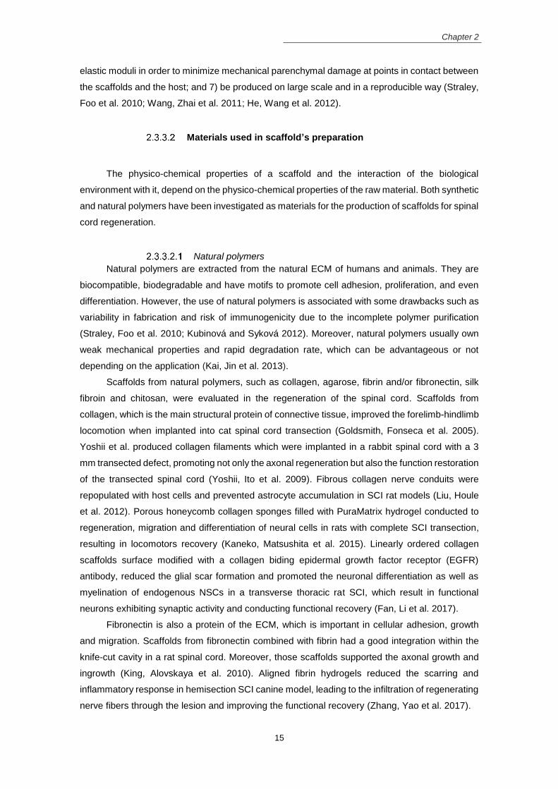
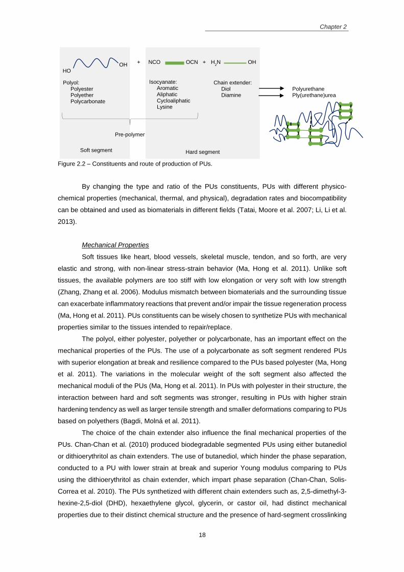
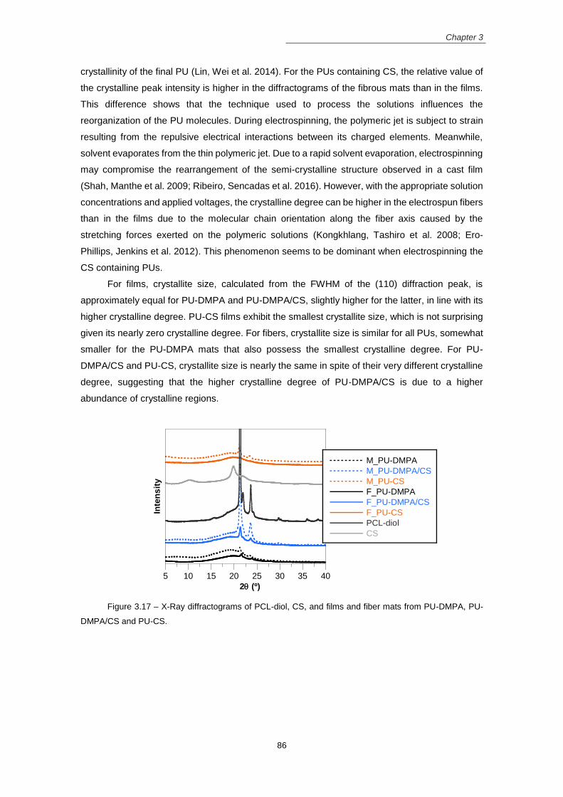
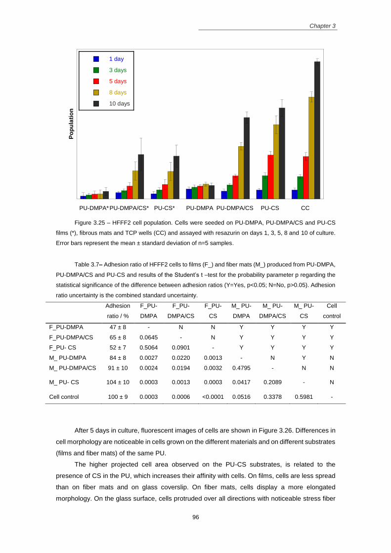
Figure 2.1 – Pathophysiological events occurring after SCI, including the primary, secondary and
chronic phases. (reproduced with permission from (Mothe and Tator 2013))
2.2 Limited spinal cord regeneration capacity
The inflammatory events in the acute phase are necessary to prevent infections, clear the
debris tissue and close the blood-brain barrier, restraining the lesion site. However, in the chronic
stage, inflammation, myelin debris and glial scar formation limit the axonal regeneration and
consequently, the capacity of the spinal cord to restore their functions after an injury. The scar
formed after the injury is a hostile environment with inhibitory molecules and proteoglycans
without the ability to support the neuronal cells; therefore, acting as a chemical and physical
barrier to the axonal regeneration (Yiu and He 2006).
The inhibitory molecules released after SCI that limit the spinal cord regeneration are:
myelin-associated proteins that inhibit axonal growth such as, oligodendrocyte myelin protein –
Vascular endothelial growth factor (VEGF)-releasing fibrin gel
Cell survival to print and migrated and proliferated
(Lee, Polio et al. 2010)
Collagen and chitosan
Membranes Spinal cord rat derived NSCs - neurospheres
EGF, bFGF Cells survive, migrate, and differentiate into astrocytes, neurons and oligodendrocytes. The differentiated cells are also supported by the membrane
(Yang, Mo et al. 2010)
Collagen and heparan sulfate proteoglycan (HPSG)
Freeze-drying porous tubes
Primary rat NSCs
bFGF (from HPSG) NSCs adhesion and proliferation
(Wang, Zhou et al. 2012)
Collagen chemically conjugated with cetuximab (EGFR antagonist)
Freeze-drying Rat NPCs B27 supplement Scaffold support cells proliferation; promote neuronal differentiation while decrease the differentiation in astrocytes
(Li, Xiao et al. 2013)
Collagen Freeze-drying (Porous scaffold)
Rat NSCs (from telencephalon of newborn rats)
Scaffolds functionalized with three neurotrophic factors (BDNF, NT3 and bFGF) and two neutralizing proteins (Epha4LBD and PlexinB1LBD), Culture medium with 2% B27 and myelin
NSCs differentiated into functional mature neurons into the functionalized scaffolds that had neuroprotective effects, even in the presence of myelin derived inhibitory molecules.
(Li, Liu et al. 2016)
Gelatin Gel forming Human NSCs Basic fibroblast growth factor (bFGF)
Support adhesion and growth and differentiation in neurons
(Chen, Chiou et al. 2006)
Gelatin Sponges Rat NSCs and Schwann cells
NSCs and SCs transfected with vectors carrying TrkC gene and NT-3 gene, respectively
NSCs differentiated into neurons with the capacity to form structural and functional connections with each other
(Lai, Wang et al. 2013)
Gelatin crosslinked with genipin
3D porous scaffold with longitudinal oriented microchannels (freeze-drying technique)
PC12 pheochromocytoma cells; and endothelial cells (co-culture)
NGF Promote neurite alignment and outgrowth (even without NGF); Without endothelial cells neuritogenesis was not observed
(Saglam, Perets et al. 2013)
Chapter 2
24
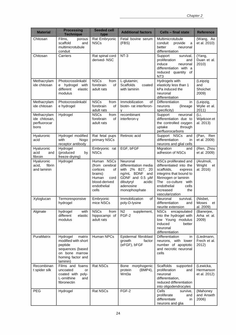
Material Processing Technique
Seeded cell type
Additional factors Cells – final state Reference
Chitosan Films, porous scaffold and multimicrotubule conduit
Rat Embryonic NSCs
Fetal bovine serum (FBS)
Multimicrotubule conduit provide a better neuronal differentiation
(Wang, Ao et al. 2010)
Chitosan Carriers Rat spinal cord derived- NSC
NT-3 Support survival, proliferation and induce neuronal differentiation with a reduced quantity of NT3
(Yang, Duan et al. 2010)
Methacrylamide chitosan
Photocrosslinkable hydrogel with different elastic modulus
NSCs from forebrain of adult rats
L-glutamin; Scaffolds coated with laminin
Hydrogels with elasticity less than 1 kPa induced the neuronal differentiation
(Leipzig and Shoichet 2009)
Methacrylamide chitosan
Photocrosslinkable hydrogel
NSCs from forebrain of adult rats
Immobilization of biotin- rat interferon- γ
Differentiation in neurons (lineage specificity)
(Leipzig, Wylie et al. 2011)
Methacrylamide chitosan, perfluorocarbons
Hydrogel NSCs from forebrain of adult rats
recombinant interferon-γ
Support neuronal differentiation due to the controlled oxygen uptake through perfluorocarbons
(Li, Wijekoon et al. 2013)
Hyaluronic acid
Hydrogel modified with Nogo receptor antibody
Rat fetal pups primary NSCs
Retinoic acid Support NSCs and differentiation in neurons and glial cells
(Pan, Ren et al. 2009)
Hyaluronic acid and fibroin
Hydrogel (produced by freeze-drying)
Embryonic rat NSCs
EGF, bFGF Migration and adhesion of NSCs
(Ren, Zhou et al. 2009)
Hyaluronic acid, fibrin and laminin
Hydrogel Human NSCs (from cerebral cortices of brains) Human cord blood-derived endothelial cells
Neuronal differentiation media with 2% B27, 20 ng/mL BDNF and GDNF and 0.5 µM dibutyryl acidic adenosine monophosphate
NSCs proliferated and differentiated into the scaffolds, express integrins that bound to fibrinogen or laminin The co-culture with endothelial cells increased the vascularization
(Arulmoli, Wright et al. 2016)
Xyloglucan Termoresponsive hydrogel
Embryonic mice NSCs
Immobilization of poly-D-lysine
Neuronal survival, differentiation and neurite extension
(Nisbet, Moses et al. 2009)
Alginate hydrogel with different elastic modulus
NSCs from hippocampi of adult rats
N2 supplement, FGF-2
NSCs encapsulated into the hydrogel with low Young modulus induced better neuronal differentiation
(Banerjee, Arha et al. 2009)
PuraMatrix Hydrogel matrix modified with short peptide sequences (based on bone marrow homing factor and laminin)
Human NPCs Epidermal fibroblast growth factor (eFGF), bFGF
Differentiation in neurons, with lower number of apoptotic and necrotic neuronal cells
(Liedmann, Frech et al. 2012)
Recombinant spider silk
Films and foams uncoated or coated with poly-L-ornithine and fibronectin
Rat NSCs Bone morphogenic protein (BMP4), Wnt3a
Scaffolds supported proliferation and neuronal differentiation, reduced differentiation into oligodendrocytes
(Lewicka, Hermanson et al. 2012)
PEG Hydrogel Rat NSCs FGF-2 Cells survive, proliferate and differentiate in neurons and glia
(Mahoney and Anseth 2006)
Chapter 2
25
Material Processing Technique
Seeded cell type
Additional factors Cells – final state Reference
PEG and poly(3,4-ehylenedioxythiophene) (PEDOT)
Films Primary NSCs from post-natal mouse brains; P19 pluripotent embryonic carcinoma cells
Differentiation of both cell types into neurons due to the downregulation of the Akt signaling pathway and the increase in expression of dual oxidase 1
(Ostrakhovitch, Byers et al. 2012)
PEG with peptide ligands
Hydrogel (placed over a collagen coated coverslip)
PC12 cells (encapsulated in the hydrogel)
NGF The hydrolytic degradation release the cells from the hydrogel that proliferate and differentiate into neurons (due to the peptide ligands)
(Zustiak, Pubill et al. 2013)
PLGA Macroporous rods produced by thermally induced phase separation
Rat pups NSCs
NSCs transfected with NT-3 or its receptor TrkC gene
Differentiation in neurons, establish connections, exhibit synaptic activity
(Xiong, Zeng et al. 2009)
Poly(3-hydroxybutyrate-co-3-hydroxyvalerate)
Microspheres produced by emulsion-solvent-evaporation technique
Embryonic mouse NSCs
Microspheres coated with PLL; Brain derived neurotrophic factor (BDNF)
Differentiation in neurons (with low levels of maturation)
(Chen and Tong 2012)
2.4.2 In vivo studies
Scaffolds with NSPCs were implanted in rat and/or mice in vivo SCI models, to evaluate
the interaction of cell-scaffold constructs with the host tissue. Hydrogels have been widely studied
for spinal cord injury repair because they can be directly injected into the lesion site and gel in
situ, making those scaffolds less invasive. Hydrogels had beneficial effects in axonal recovery;
however, they provided low mechanical support and impaired the infiltration and survival of cells
inside their structure. Several reviews have discussed the role of the hydrogels as a vehicle for
cell transplantation in spinal cord regeneration (Nomura, Tator et al. 2006; Willerth and Sakiyama-
Elbert 2007; Zhong and Bellamkonda 2008; Madigan, McMahon et al. 2009).
Porous sponges and multichannel scaffolds from either natural or synthetic polymers were
appropriate vehicles for NSPCs allowing their survival and differentiation in in vivo SCI animal
models. Scaffolds from PLGA, with an inner part with macroporous structure and an outer part
with oriented structure, seeded with NSCs reduced the tissue loss and the glial scar, promoting
functional recovery at some extent (Teng, Lavik et al. 2002). A chitosan tubular construct with
NSCs bridge the lesion site, connecting the transected cord stumps with integration of host
neurons (Zahir, Nomura et al. 2008). Collagen porous scaffolds with oriented pores and NSCs
aligned the reparative tissue with the direction of the spinal cord, reducing the formation of fluid-
filled cysts and preventing the collapse of musculature and connective tissue into the lesion site
(Cholas, Hsu et al. 2012). The same scaffold functionalized with an epidermal growth factor
receptor (cetuximab) improved the functional recovery (Li, Xiao et al. 2013). Recently, NSCs in a
Chapter 2
26
collagen porous scaffold modified with three neurotrophic factors (BDNF, NT3 and bFGF) and
two neutralizing proteins (Epha4LBD and PlexinB1LBD), all modified with a collagen biding
domain, stimulated the endogenous neurogenesis in the lesion and improve the hosted NSCs
survival and differentiation into motor and sensory neurons, which can establish synapsis
between them and the host neurons (Li, Liu et al. 2016).
Scaffolds with both NSCs and Schwann cells induced spinal cord functional recovery due
to the presence of Schwann cells, which released neurotrophic factors to promote survival and
axonal regeneration of injured neurons (Chen, Hu et al. 2010). Using those cells but transfected
with adenoviral vectors carrying TrkC gene and NT-3 gene into gelatin sponges, created a
suitable environment to form a neural network derived from the NSCs that was well integrated
into the host neuronal network, which is a way to conduct signals from the brain to the hindlimbs,
providing the functional recovery (Lai, Wang et al. 2013) and also increasing the remyelination
(Lai, Wang et al. 2013). Ensheathing the gelatin sponges with a thin PLGA film formed a tubular
structure, which improved the axonal regeneration, the synaptogenesis and the locomotor
function, and decrease the injury site cavity (Du, Zeng et al. 2015). The NT-3 embedded into a
tubular scaffold from a block copolymer of poly(Ɛ-caprolactone)-block-poly(l-lactic acid-co-Ɛ-
caprolactone) coated with silk fibroin instead of using genetically modified NSCs also promoted
functional recovery and axonal regeneration (Tang, Liao et al. 2014).
2.5 Role of scaffold topography in stem cell differentiation
In the last years, the emergence of the nanotechnology/microtechnology allowed the
manipulation of the materials at nanometric/micrometric scale. At the submicron scale the
scaffolds can be designed to resemble many of the topographical features of the ECM, closely
interacting with the cells and influencing their behavior.
The ECM is a fibrous acellular matrix of molecules, which confer structural support to the
surrounding cells and modulates cellular activities such as migration, proliferation, differentiation,
gene expression and secretion of growth factors. The ECM forms a highly structured local
microenvironment that allows the transport of oxygen and nutrients and the removal of waste
products, allowing cellular metabolism and communication (Lim and Mao 2009; Zhao, Tan et al.
2012). The ECM of the CNS has a composition different from the ECM in most tissues of the
body. In the CNS, the interstitial matrix contains small quantities of fibrillar proteins and
glycoproteins. Instead, they are formed by a network of proteoglycans, hyaluronan, tenascins and
link proteins, which act not only as the mechanical support to the tissue but also as the scaffold
during development of adult neurogenesis (Zimmermann and Dours-Zimmermann 2008). In
addition, the soma and dendrites of the neuronal cell are surrounded by a high-density ECM
aggregates named perineuronal nets. In their niches, the NSCs were also surrounded by ECM
and closely interact with it by expressing adhesion molecules (Bond, Ming et al. 2015).
Chapter 2
27
As the cells sense the scaffolds characteristics at nano/micro-scale level – as an artificial
ECM, mechanical signals are generated and translated by intracellular signaling pathways,
regulating the genomic expression and the cell fate. This mechanism is called
mechanotransduction and integrins and focal adhesions take an important role on it (Figure 2.3)
(Lutolf and Hubbell 2005). The integrins mediate the adhesion of the cell to the ECM. When
integrins are bounded both conformation and affinity are changed, resulting in integrin clustering
and immature focal complexes formation. The focal complexes bind to actin linker proteins, which
result in stress fiber formation and increase focal adhesion site and cytoskeletal tension
(McMurray, Dalby et al. 2014). The integrin clustering depends on the sensed topography and
stiffness, and activate specific signaling pathways important for cellular function (migration,
proliferation and differentiation) (Gjorevski and Nelson 2009). Focal adhesions link the actin
cytoskeleton to the transmembrane integrins, experiencing forces that actin exerts on the
adhesion sites, which varied with the sensed topography and stiffness and resulted in alterations
in the cellular differentiation (McMurray, Dalby et al. 2014). The structural organization of the
nucleus and gene and protein expression are also influenced by topographical factors (Teo,
Ankam et al. 2010). The biophysical signals are transduced to the nucleus by soluble regulatory
factors through nuclear pores (Yim and Sheetz 2012).
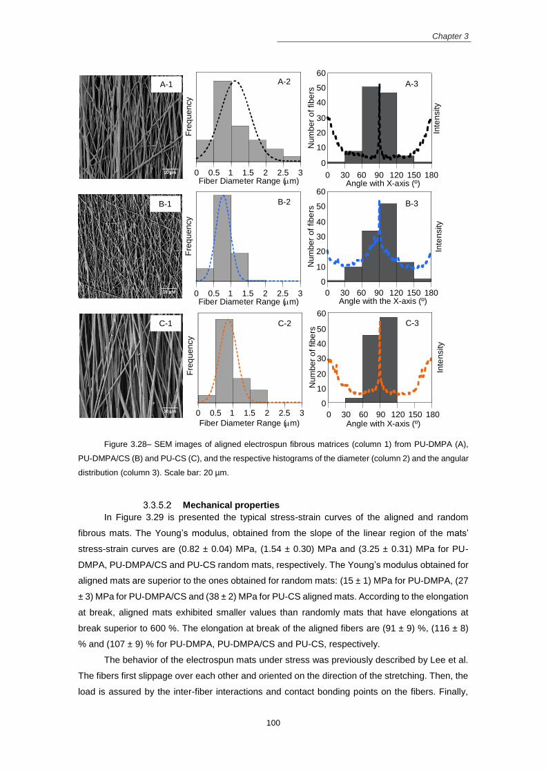
Figure 2.3 – Cells mechanosensors are stimulated by external mechanical forces. (A) Multiple forces
activated the signaling pathways, modulating the gene expression, and consequently, protein expression
and cellular functions. (B) Focal adhesion experiencing the balance of the external (Fext) and internal forces
(Fcell) in driving stress at a mechanosensor (reproduced with the permission of McMurray 2014)
Chapter 2
28
The lack of a functional ECM at the lesion site is one of the causes that impair the
regeneration of the SCI because the cells (either transplanted or from the host) require a
functional ECM to survive and functionally integrate into the tissue (He, Wang et al. 2012; Purcell,
Naim et al. 2012). Therefore, a scaffold that mimic the ECM of the NSCs niche will support the
NSCs and guide their behavior inside the injury and, consequently, will assist the proper spinal
cord regeneration.
2.5.1 Nano/micro-scale scaffolds
Techniques such as, peptide self-assembly, phase separation, lithography and
nanoimprinting and electrospinning can modify/produce substrates with nano/micro-scale
topographies to guide the NSCs behavior.
2.5.2 Self-assembly nanofibers
Self-assembly technique allows the production of nanofibers from custom-designed
peptide-like amphiphiles that spontaneously assemble and organize by using positive and
negative L-amino acids (Ellis-Behnke, Liang et al. 2009). Excellent control over the substrate
chemistry and the nanoscale features of the resulting fibers are attractive characteristics of this
technique. However, it is a very time consuming and expensive technique due to the difficulty in
the optimization of the design, structure and stability of the peptide sequences (Rim, Shin et al.
2013).
Interaction of NSCs with self-assembly peptide nanofibers and
SCI treatment
3D hydrogels of nanofibers formed by self-assembly of peptide amphiphilic molecules were
designed to interact with NPCs. The Ac-(Asp-Ala-Asp-Ala)4-CONH2 – RADA-16 is a synthetic
amphiphilic peptide of 16 aminoacids that could self-assemble in a well-defined nanofiber
structure (~10 nm) and form a 3D hydrogel. Self-assembled structures from this peptide sequence
can be easily functionalized with cell adhesion and differentiation motifs, which are better
substrates for NSCs than the self-assembled hydrogels without modification. The different motifs
such as, functional motifs from bone marrow homing peptides – SKPPGTSS, bone marrow
phosphate) electrospun nanofibers incorporated into a collagen scaffolds formed a hybrid
construct able to guide neurite extension, support new vessels formation and integrate well into
Chapter 2
36
the host tissue of rats with hemi-section SCI model (Milbreta, Nguyen et al. 2016). However, the
functional recovery was not significant compared to the animals with injuries and without
scaffolds. Therefore, the same scaffold was encapsulated with NT3 and miR-22 (that control the
local protein synthesis at distal axons), providing not only topographical but also biochemical
cues, reducing the excessive inflammatory response and the scar tissue formation in the hemi-
sected rats (Nguyen, Gao et al. 2017). However, no functional tests were performed.
Neuronal cell’s interaction with electrospun fibrous mats
Polymeric nano/microfibrous matrices produced by electrospinning closely resemble the
topography of the CNS ECM, providing the right guidance cues to the neural/neuronal cells. The
electrospun fibrous substrates increased the neuritogenesis and neurite outgrowth of rat spinal
cord motor neurons compared to thin films without any topographical cue (Gertz, Leach et al. 2010).
Several in vitro and in vivo studies have explored the use of the electrospun mats to support and
guide the development of embryonic neurons as well as the regenerating neurons. Those studies
are briefly summarized in Table 2.2.
In neurons, the neurite growth cone at the tip of the axon regulates neurite outgrowth and
sense the guidance cues. The nanofibers interact intimately with the growth cone, providing the
contact guidance signals to induce the axonal growth (Nisbet, Forsythe et al. 2009). Nanofibrous
scaffolds with aligned morphology oriented the neurite outgrowth exactly parallel to the nanofiber
axis (Corey, Gertz et al. 2008; Xie, MacEwan et al. 2009). This is an important cue in SCI
regeneration, since neurites can reach longer distances from one end to the other of the lesion
site (Meiners, Ahmed et al. 2007; Hurtado, Cregg et al. 2011). On the opposite, the misalignment
of fibers prevent neurite outgrowth, which delay the axonal extension from one end to the other
of the injury, delaying the regeneration process (Wang, Mullins et al. 2008). However, fiber
density, surface chemistry and surface properties of the fibrous matrices can have stronger
influence than the fiber alignment and the neurites cannot align along the fibers direction (Xie, Liu
et al. 2014). In regions with high fiber density, the neurites perfectly align perpendicular to the
fiber alignment with in lower densities the fibers neurites follow the fiber alignment, increasing the
neurite outgrowth. However, in high density fibers coated with laminin the neurites also extend in
the direction of the fiber alignment.
The presence of ECM proteins such as laminin can thus improve the neurite outgrowth.
The increased immobilization of laminin on electrospun fibrous mats conducted to superior neurite
outgrowth of neuron-like PC12 cells (Zander, Orlicki et al. 2012). The FGF-2 growth factor, which
is important in neurogenesis, also conducted to superior neurite outgrowth and axonal extension
of rat dorsal root ganglia when immobilized on polyamide nanofibers (Delgado-Rivera, Harris et
al. 2009). Collagen nanofibers can adsorb NT-3 and chABC factors, which were controlled
release, resulting in superior neurite extension of rat dorsal root ganglia depending on the NT-3
concentration (Liu, Xu et al. 2012).
Chapter 2
37
Another topographical signal that influence the neuronal behavior is the diameter of the
fibers. PLLA aligned fibers with smaller diameter (300 nm) impaired neurite outgrowth while larger
fibers (700 and 1300 nm) increased their growth (Wang, Mullins et al. 2010). On the opposite, silk
fibroin fibers with 400 nm diameter were better substrates for neurite outgrowth of rat cortical
neurons relative to fibers with 800 nm and 1200 nm diameters (Qu, Wang et al. 2013). Better
neurite outgrowth and the formation of a 3D neuronal network was observed in PU fibers with
similar diameter ranges (450 nm) (Puschmann, de Pablo et al. 2014). Although the contradictory
results, the chemical structure of the polymer as well as the alignment degree of the fibers were
different between the studies, making it difficult to compare the results and define the better
diameters range for neurite outgrowth. However, fiber diameters in the range of 400 – 700 nm
could be the preferred choice to increase the neurite outgrowth, instead of microfibers or
nanofibers with smaller diameters (< 300 nm).
Therefore, fibers with aligned morphology, diameters ranging from 400 nm to 700 nm and
a surface presenting ECM proteins or growth factors seems to be appropriate substrates for
neuritogenesis and neurite outgrowth.
Chapter 2
38
Table 2.2 – Effects of the electrospun nanofibers on nerve cells.
Material/ scaffold
Nerve cell type Additional factors Effects on cells Reference
PLLA (aligned nanofibers)
Primary motor and sensory neurons (from rat spinal cord)
Coating substrates with PLL and collagen I for motor and sensory neurons, respectively
Directed neurite outgrowth in fiber direction
(Corey, Gertz et al. 2008)
PLLA (aligned nanofibers)
Chicks primary dorsal root ganglia; rat Schwann cells
Coating substrates with PLL
Guided neurite outgrowth in fiber direction; Schwann cells grew along the aligned fibers
(Wang, Mullins et al. 2008)
PLLA (nanofibers vs. films)
Rat spinal cord primary motor neurons
Coating substrates with PLL
Nanofibers accelerated the neuritogenesis and major neurite growth while restricted dendritic maturation and soma spreading
(Gertz, Leach et al. 2010)
PLLA (aligned nanofibers with diameters: 300, 700, and 1300 nm )
Rat dorsal root ganglia and Schwann cells
Higher neurite alignment on fibers with superior diameter and densely packed
(Wang, Mullins et al. 2010)
PCL (aligned nanofibers)
Embryonic chicks primary dorsal root ganglia
Coating fibers with laminin
Neurites preferential extended along the long axis of nanofiber matrice; Increased guidance with laminin
(Xie, MacEwan et al. 2009)
PCL (nanofibers surface modified)
Neuron-like PC12 cells
Covalent attachment of laminin
Neurite outgrowth increase with the increase of the attached laminin
(Zander, Orlicki et al. 2012)
PCL (aligned nanofibers – fiber density, and surface chemistry)
Chick dorsal root ganglion
Coated with poly-L-lysine (PLL) and laminin
Neurites grew parallel to the fiber alignment or perpendicular to it if the fibers were not coated with laminin or coated with PEG
(Xie, Liu et al. 2014)
Polydioxanone nanofibers (aligned vs. random)
Rat dorsal root ganglia; rat astrocytes
Coating substrates with PLL
Both neurites and astrocytes aligned in the direction of the electrospun fibers; Neurites grew more robustly and extended longer processes when co-cultured with astrocytes
(Chow, Simpson et al. 2007)
Polyamide (nanofibers surface modified)
Rat dorsal root ganglia and non-reactive astrocytes
Fibers covalently modified with FGF-2
Higher neurite outgrowth and axonal extension in nanofibers with FGF-2 modification
(Delgado-Rivera, Harris et al. 2009)
Polyurethane (nanofibers with diameters: 450 nm, 1350 nm, 2500 nm)
Mice embryonic hippocampus neurons (Co-culture with astrocytes)
Fibers coated with poly-D-lysine;
Neurite outgrowth was superior in fibers with 450 nm diameter while the astrocytes were less proliferative
(Puschmann, de Pablo et al. 2014)
Collagen nanofibers (aligned vs. random)
Prymary rat astrocytes and dorsal root ganglia neurons
Aligned nanofibers directed the orientation of neurites and astrocytes; In randomly oriented fibers the astrocytes spared radially
(Liu, Houle et al. 2012)
Collagen (nanofibers as drug delivery system)
Rat dorsal root ganglia
Incorporation of NT-3 and chABC in fibers
The neurite extension was increased depending on the NT-3 concentration loaded on the fibers
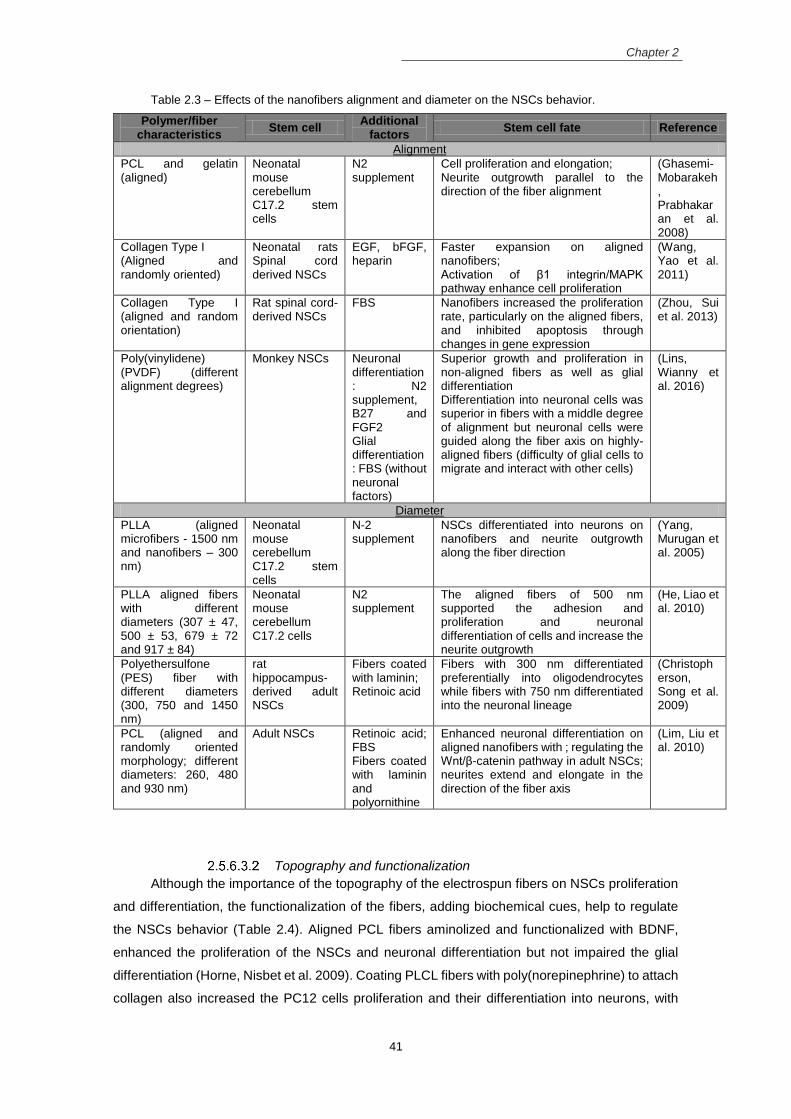
Superior growth and proliferation in non-aligned fibers as well as glial differentiation Differentiation into neuronal cells was superior in fibers with a middle degree of alignment but neuronal cells were guided along the fiber axis on highly-aligned fibers (difficulty of glial cells to migrate and interact with other cells)
NSCs differentiated into neurons on nanofibers and neurite outgrowth along the fiber direction
(Yang, Murugan et al. 2005)
PLLA aligned fibers with different diameters (307 ± 47, 500 ± 53, 679 ± 72 and 917 ± 84)
Neonatal mouse cerebellum C17.2 cells
N2 supplement
The aligned fibers of 500 nm supported the adhesion and proliferation and neuronal differentiation of cells and increase the neurite outgrowth
(He, Liao et al. 2010)
Polyethersulfone (PES) fiber with different diameters (300, 750 and 1450 nm)
rat hippocampus-derived adult NSCs
Fibers coated with laminin; Retinoic acid
Fibers with 300 nm differentiated preferentially into oligodendrocytes while fibers with 750 nm differentiated into the neuronal lineage
(Christopherson, Song et al. 2009)
PCL (aligned and randomly oriented morphology; different diameters: 260, 480 and 930 nm)
Adult NSCs Retinoic acid; FBS Fibers coated with laminin and polyornithine
Enhanced neuronal differentiation on aligned nanofibers with ; regulating the Wnt/β-catenin pathway in adult NSCs; neurites extend and elongate in the direction of the fiber axis
(Lim, Liu et al. 2010)
Topography and functionalization
Although the importance of the topography of the electrospun fibers on NSCs proliferation
and differentiation, the functionalization of the fibers, adding biochemical cues, help to regulate
the NSCs behavior (Table 2.4). Aligned PCL fibers aminolized and functionalized with BDNF,
enhanced the proliferation of the NSCs and neuronal differentiation but not impaired the glial
differentiation (Horne, Nisbet et al. 2009). Coating PLCL fibers with poly(norepinephrine) to attach
collagen also increased the PC12 cells proliferation and their differentiation into neurons, with
Chapter 2
42
superior extension and number of neurites (Taskin, Xu et al. 2015). The immobilization of RE-1
silencing transcriptional factor (REST) small interference RNA (siRNA) (gene delivery vector) on
the PCL nanofibers surface via polydopamine coating, increased the NSCs differentiation into
functional neurons while reduced their differentiation into astrocytes, when compared to the PCL
film also immobilized with REST (Low, Rujitanaroj et al. 2013).
Similar to the electrospinning technique, the “spinneret based tunable engineered
parameters” (STEP) technology (use a metal micropipette and without an electrical field) was
used in the production of polystyrene nanofibers with aligned configuration (one layer) and
crosshatch (double layer) configuration (Bakhru, Nain et al. 2011). The scaffolds were
functionalized with poly-L-ornithine and laminin and NSCs were seeded on them. The cells
presented a polarized morphology and follow the alignment of the fibers, differentiating mainly
into neurons. However, cells were also seeded in a planar structure in close proximity to the cells
on the fibers. The cells on the planar structure were also differentiated into the neuronal lineage,
suggesting that a paracrine effect influenced the cells near to the ones on the fibers (Bakhru, Nain
et al. 2011).
However, neurotrophic factors such as BDNF can also be encapsulated in the electrospun
nanofibibers (from a copolymer of Ɛ-caprolactone and ethyl ethylene phosphate) (Low,
Rujitanaroj et al. 2013). The controlled release of BDNF associated with the topographical cues
of the scaffolds induced superior neuronal differentiation of mouse NSCs. The incorporation of
molecules such as retinoic acid and purmorphamine on the gelatin outer shell, on fibers with a
core-shell structure produced using co-axial electrospinning, enhanced the differentiation of
NSCs into motor neurons and improved the neurite extension (Binan, Tendey et al. 2014).
The own polymer used to construct the fibrous scaffolds also influenced the cell behavior.
The functional groups of collagen can interact with β1 integrin and activate MAPK signaling
cascade on the neonatal rat spinal cord derived NSCs, enhancing the cell proliferation (Wang,
Yao et al. 2011). Even without the aligned morphology, the fibrous scaffolds from chitosan were
a better choice for the NSCs proliferation and neuronal differentiation when compared to fibers
from either cellulose acetate or polyethersulfone (Du, Tan et al. 2014), reinforcing the importance
to choose the appropriate polymer to produce the electrospun mats for NSCs interaction.
Therefore, the combinatorial effects of nanostructure of the scaffolds and the biochemical
cues from the neurotrophic factors or other molecules are important in driving the NSPCs
behavior. Even with that, additional factors must be added to the culture medium to promote the
suitable cell maintenance (EGF, bFGF, FGF2) and to induce the neuronal (retinoic acid, N2
supplement) and the glial (FBS) differentiation.
Chapter 2
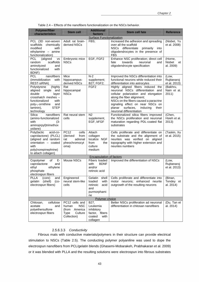
43
Table 2.4 – Effects of the nanofibers functionalization on the NSCs behavior.
Increased the adhesion and spreading over all the scaffold NSCs differentiate primarily into oligodendrocytes in the presence of FBS
(Nisbet, Yu et al. 2008)
PCL (aligned vs random scaffolds aminolyzed and functionalized with BDNF)
Embryonic mice NSCs
EGF, FGF2 Enhance NSC proliferation; direct cell fate towards neuronal and oligodendrocyte specification
(Horne, Nisbet et al. 2009)
PCL nanofibers (immobilization with REST-siRNA)
Mice hippocampus-derived NSCs
N-2 supplement; B27; FGF2;
Improved the NSCs differentiation into functional neurons while reduced their differentiation into astrocytes
(Low, Rujitanaroj et al. 2013)
Polystyrene (highly aligned single and double layer crosshatch meshes – functionalized with poly-L-ornithine and laminin), STEP technology
Rat hippocampal NSCs
FGF2 Highly aligned fibers induced the neuronal NSCs differentiation and cellular polarization and elongation along the fiber alignment; NSCs on the fibers caused a paracrine signaling effect on near NSCs on planar surfaces, inducing their neuronal differentiation
(Bakhru, Nain et al. 2011)
Silica nanofibers (amino-functionalized with (3-aminoprpyl)trimethoxysilane)
Rat neural stem cells
N2 supplement, EGF, bFGF
Functionalized silica fibers improved the NSCs proliferation and neuronal maturation regarding PDL-coated flat substrates
(Chen, Hsieh et al. 2013)
Poly(lactic acid-co-caprolactone) (PLCL) (aligned and random orientation – coated with poly(norepinephrine) to attach collagen)
PC12 cells (derived from rat adrenal pheochromocytoma)
Attach collagen localize NGF from the culture medium
Cells proliferate and differentiate on the substrate and the alignment of neurites was verified on aligned topography with higher extension and neurites numbers
(Taskin, Xu et al. 2015)
Encapsulation of factors
Copolymer of Ɛ-caprolactone and ethyl ethylene phosphate electrospun fibers
Mouse NSCs Fibers loaded with BDNF and/or retinoic acid
Improved the differentiation of NSCs (Low, Rujitanaroj et al. 2013)
PLLA (core) and gelatin (shell) (co-electrospun fibers)
Engineered neural stem-like cells
Gelatin shell loaded with retinoic acid and purmorphamine
Cells proliferate and differentiate into motor neurons; enhanced neurite outgrowth of the resulting neurons
(Binan, Tendey et al. 2014)
Polymer choice
Chitosan, cellulose acetate and polyethersulfone electrospun fibers
PC12 cells and human NSC (from America Type Culture Collection)
B27, Leukemia inhibitory factor, fibers coated with collagen
Better NSCs proliferation ad neuronal differentiation in chitosan nanofibers
(Du, Tan et al. 2014)
Conductivity
Fibrous mats with conductive materials/polymers in their structure can provide electrical
stimulation to NSCs (Table 2.5). The conducting polymer polyaniline was used to dope the
electrospun nanofibers from PCL/gelatin blends (Ghasemi-Mobarakeh, Prabhakaran et al. 2009)
or it was blended with PLLA and the resulting solutions were electrospun into fibrous substrates
Chapter 2
44
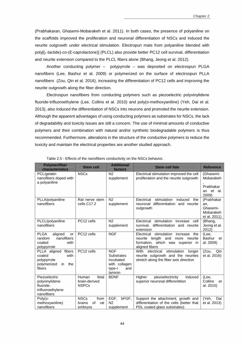
(Prabhakaran, Ghasemi-Mobarakeh et al. 2011). In both cases, the presence of polyaniline on
the scaffolds improved the proliferation and neuronal differentiation of NSCs and induced the
neurite outgrowth under electrical stimulation. Electropun mats from polyaniline blended with
poly[(L-lactide)-co-(Ɛ-caprolactone)] (PLCL) also provide better PC12 cell survival, differentiation
and neurite extension compared to the PLCL fibers alone (Bhang, Jeong et al. 2012).
Another conducting polymer – polypyrrole – was deposited on electrospun PLGA
nanofibers (Lee, Bashur et al. 2009) or polymerized on the surface of electrospun PLLA
nanofibers (Zou, Qin et al. 2016), increasing the differentiation of PC12 cells and improving the
neurite outgrowth along the fiber direction.
Electrospun nanofibers from conducting polymers such as piezoelectric polyvinylidene
fluoride-trifluoroethylene (Lee, Collins et al. 2010) and poly(o-methoxyaniline) (Yeh, Dai et al.
2013), also induced the differentiation of NSCs into neurons and promoted the neurite extension.
Although the apparent advantages of using conducting polymers as substrates for NSCs, the lack
of degradability and toxicity issues are still a concern. The use of minimal amounts of conductive
polymers and their combination with natural and/or synthetic biodegradable polymers is thus
recommended. Furthermore, alterations in the structure of the conductive polymers to reduce the
toxicity and maintain the electrical properties are another studied approach.
Table 2.5 - Effects of the nanofibers conductivity on the NSCs behavior.
Polymer/fiber characteristics
Stem cell Additional
factors Stem cell fate Reference
PCL/gelatin nanofibers doped with a polyaniline
NSCs N2 supplement
Electrical stimulation improved the cell proliferation and the neurite outgrowth
(Ghasemi-Mobarakeh, Prabhakaran et al. 2009)
PLLA/polyaniline nanofibers
Rat nerve stem cells C17.2
N2 supplement
Electrical stimulation induced the neuronal differentiation and neurite outgrowth
(Prabhakaran, Ghasemi-Mobarakeh et al. 2011)
PLCL/polyaniline nanofibers
PC12 cells N2 supplement
Electrical stimulation increase cell survival, differentiation and neurite extension
(Bhang, Jeong et al. 2012)
PLGA aligned or random nanofibers coated with polypyrrole
PC12 cells NGF Electrical stimulation increase the neurite length and more neurite formation, which was superior in aligned fibers
(Lee, Bashur et al. 2009)
PLLA aligned fibers coated with polypyrrole polymerized in the fibers
PC12 cells NGF Substrates incubated with collagen type-I and laminin
With electrical stimulation longer neurite outgrowth and the neurites stretch along the fiber axis direction
BDNF Higher piezoelectricity induced superior neuronal differentition
(Lee, Collins et al. 2010)
Poly(o-methoxyaniline) nanofibers
NSCs from brains of rat embryos
EGF, bFGF, N2 supplement
Support the attachment, growth and differentiation of the cells (better that PDL coated glass substrates)
(Yeh, Dai et al. 2013)
Chapter 2
45
2.6 References Abbasi, N., S. M. Hashemi, et al. (2015). "Influence of oriented nanofibrous PCL scaffolds on quantitative gene expression during neural differentiation of mouse embryonic stem cells." Journal of Biomedical Materials Research Part A 104(1): 155-164.
Akhavan, O. and E. Ghaderi (2013). "Differentiation of human neural stem cells into neural networks on graphene nanogrids." Journal of Materials Chemistry B 1(45): 6291-6301.
Akhavan, O., E. Ghaderi, et al. (2015). "Near infrared laser stimulation of human neural stem cells into neurons on graphene nanomesh semiconductors." Colloids and Surfaces B: Biointerfaces 126: 313-321.
Akhavan, O., E. Ghaderi, et al. (2016). "Rolled graphene oxide foams as three-dimensional scaffolds for growth of neural fibers using electrical stimulation of stem cells." Carbon 97: 71-77.
Alvarez-Mejia, L., J. Morales, et al. (2015). "Functional recovery in spinal cord injured rats using polypyrrole/iodine implants and treadmill training." Journal of Materials Science: Materials in Medicine 26(7):
1-11. Alves-Sampaio, A., C. García-Rama, et al. (2016). "Biofunctionalized PEDOT-coated microfibers for the treatment of spinal cord injury." Biomaterials 89: 98-113.
Anton, F. (1934). Process and apparatus for preparing artificial threads, Google Patents. Arulmoli, J., H. J. Wright, et al. (2016). "Combination scaffolds of salmon fibrin, hyaluronic acid, and laminin for human neural stem cell and vascular tissue engineering." Acta biomaterialia 43: 122-138.
Bagdi, K., K. Molná, et al. (2011). "Specific interactions, structure and properties in segmented polyurethane elastomers." eXPRESS Polym Lett 5: 417.
Bai, S., W. Zhang, et al. (2014). "Silk nanofiber hydrogels with tunable modulus to regulate nerve stem cell fate." Journal of Materials Chemistry B 2(38): 6590-6600.
Bakhru, S., A. S. Nain, et al. (2011). "Direct and cell signaling-based, geometry-induced neuronal differentiation of neural stem cells." Integrative Biology 3(12): 1207-1214.
Banerjee, A., M. Arha, et al. (2009). "The influence of hydrogel modulus on the proliferation and differentiation of encapsulated neural stem cells." Biomaterials 30(27): 4695-4699.
Béduer, A., C. Vieu, et al. (2012). "Engineering of adult human neural stem cells differentiation through surface micropatterning." Biomaterials 33(2): 504-514.
Benson, M. D., M. I. Romero, et al. (2005). "Ephrin-B3 is a myelin-based inhibitor of neurite outgrowth." Proceedings of the national academy of sciences of the United States of America 102(30): 10694-10699.
Bhang, S. H., S. I. Jeong, et al. (2012). "Electroactive Electrospun Polyaniline/Poly [(L‐lactide)‐co‐(ε‐caprolactone)] Fibers for Control of Neural Cell Function." Macromolecular bioscience 12(3): 402-411.
Bhardwaj, N. and S. C. Kundu (2010). "Electrospinning: a fascinating fiber fabrication technique." Biotechnology Advances 28(3): 325-347.
Binan, L., C. Tendey, et al. (2014). "Differentiation of neuronal stem cells into motor neurons using electrospun poly-l-lactic acid/gelatin scaffold." Biomaterials 35(2): 664-674.
Blesch, A. and M. H. Tuszynski (2009). "Spinal cord injury: plasticity, regeneration and the challenge of translational drug development." Trends in neurosciences 32(1): 41-47.
Bond, A. M., G.-l. Ming, et al. (2015). "Adult mammalian neural stem cells and neurogenesis: five decades later." Cell stem cell 17(4): 385-395.
Bonner, J. F. and O. Steward (2015). "Repair of spinal cord injury with neuronal relays: From fetal grafts to neural stem cells." Brain research 1619: 115-123.
Bozkurt, G., A. J. Mothe, et al. (2010). "Chitosan channels containing spinal cord-derived stem/progenitor cells for repair of subacute spinal cord injury in the rat." Neurosurgery 67(6): 1733-1744.
Bradbury, E. J., L. D. Moon, et al. (2002). "Chondroitinase ABC promotes functional recovery after spinal cord injury." Nature 416(6881): 636-640.
Chapter 2
46
Brännvall, K., K. Bergman, et al. (2007). "Enhanced neuronal differentiation in a three‐dimensional collagen‐hyaluronan matrix." Journal of neuroscience research 85(10): 2138-2146.
Braughler, J. M. and E. D. Hall (1989). "Central nervous systems trauma and stroke: I. Biochemical considerations for oxygen radical formation and lipid peroxidation." Free Radical Biology and Medicine 6(3):
289-301. Caprini, A., D. Silva, et al. (2013). "A Novel Bioactive Peptide: Assessing its Activity Over Murine Neural Stem Cells and its Potential for Neural Tissue Engineering." New biotechnology. Carlberg, B., M. Z. Axell, et al. (2009). "Electrospun polyurethane scaffolds for proliferation and neuronal differentiation of human embryonic stem cells." Biomedical Materials 4(4): 045004.
Casper, C. L., J. S. Stephens, et al. (2004). "Controlling surface morphology of electrospun polystyrene fibers: effect of humidity and molecular weight in the electrospinning process." Macromolecules 37(2): 573-
578. Chan-Chan, L., R. Solis-Correa, et al. (2010). "Degradation studies on segmented polyurethanes prepared with HMDI, PCL and different chain extenders." Acta Biomaterialia 6(6): 2035-2044.
Chan-Chan, L., C. Tkaczyk, et al. (2013). "Characterization and biocompatibility studies of new degradable poly (urea) urethanes prepared with arginine, glycine or aspartic acid as chain extenders." Journal of Materials Science: Materials in Medicine 24(7): 1733-1744.
Chen, G., Y.-r. Hu, et al. (2010). "Functional recovery following traumatic spinal cord injury mediated by a unique polymer scaffold seeded with neural stem cells and Schwann cells." Chinese Medical Journal (English Edition) 123(17): 2424.
Chen, W. and Y. W. Tong (2012). "PHBV microspheres as neural tissue engineering scaffold support neuronal cell growth and axon–dendrite polarization." Acta Biomaterialia 8(2): 540-548.
Chen, W. S., P. H. Hsieh, et al. (2013). "Chemically modified electrospun silica nanofibers for promoting growth and differentiation of neural stem cells." Journal of Materials Chemistry B 9: 1205-1215. Chen, Y.-W., S.-H. Chiou, et al. (2006). Using gelatin scaffold with coated basic fibroblast growth factor as a transfer system for transplantation of human neural stem cells. Transplantation proceedings, Elsevier 38(5): 1616-1617.
Cheng, H., Y.-C. Huang, et al. (2007). "Laminin-incorporated nerve conduits made by plasma treatment for repairing spinal cord injury." Biochemical and biophysical research communications 357(4): 938-944.
Cherry, J., A. Carlson, et al. (2012). "Oriented, Multimeric Biointerfaces of the L1 Cell Adhesion Molecule: An Approach to Enhance Neuronal and Neural Stem Cell Functions on 2-D and 3-D Polymer Substrates." Biointerphases 7(1-4): 1-16.
Cholas, R. H., H.-P. Hsu, et al. (2012). "The reparative response to cross-linked collagen-based scaffolds in a rat spinal cord gap model." Biomaterials 33(7): 2050-2059.
Chow, W. N., D. G. Simpson, et al. (2007). "Evaluating neuronal and glial growth on electrospun polarized matrices: bridging the gap in percussive spinal cord injuries." Neuron glia biology 3(02): 119-126.
Christopherson, G. T., H. Song, et al. (2009). "The influence of fiber diameter of electrospun substrates on neural stem cell differentiation and proliferation." Biomaterials 30(4): 556-564.
Colello, R. J., W. N. Chow, et al. (2016). "The incorporation of growth factor and chondroitinase ABC into an electrospun scaffold to promote axon regrowth following spinal cord injury." Journal of tissue engineering and regenerative medicine 10(8): 656-668.
Colombo, G., M. Wirz, et al. (2001). "Driven gait orthosis for improvement of locomotor training in paraplegic patients." Spinal Cord 39(5): 252-255.
Corey, J. M., C. C. Gertz, et al. (2008). "The design of electrospun PLLA nanofiber scaffolds compatible with serum-free growth of primary motor and sensory neurons." Acta biomaterialia 4(4): 863-875.
Costa, L. M., J. E. Pereira, et al. (2013). "Rolipram promotes functional recovery after contusive thoracic spinal cord injury in rats." Behavioural brain research 243: 66-73.
Chapter 2
47
Cruz, G. J., R. Mondragón-Lozano, et al. (2012). "Plasma polypyrrole implants recover motor function in rats after spinal cord transection." Journal of Materials Science: Materials in Medicine 23(10): 2583-2592.
De Vrieze, S., T. Van Camp, et al. (2009). "The effect of temperature and humidity on electrospinning." Journal of materials science 44(5): 1357-1362.
Delgado-Rivera, R., S. L. Harris, et al. (2009). "Increased FGF-2 secretion and ability to support neurite outgrowth by astrocytes cultured on polyamide nanofibrillar matrices." Matrix Biology 28(3): 137-147.
Dinan, B., N. Bhattarai, et al. "Characterization of Chitosan Based Hybrid Nanofiber Scaffolds for Tissue Engineering." Journal of Undergraduate Research in Bioengineering: 33-37. Du, B. L., X. Zeng, et al. (2015). "Graft of the gelatin sponge scaffold containing genetically‐modified neural
stem cells promotes cell differentiation, axon regeneration, and functional recovery in rat with spinal cord transection." Journal of Biomedical Materials Research Part A 103(4): 1533-1545.
Du, J., E. Tan, et al. (2014). "Comparative evaluation of chitosan, cellulose acetate, and polyethersulfone nanofiber scaffolds for neural differentiation." Carbohydrate polymers 99: 483-490.
Dubendorf, P. (1999). "Spinal cord injury pathophysiology." Critical care nursing quarterly 22(2): 31-35.
Duncan, I. and R. Hoffman (1997). "Schwann cell invasion of the central nervous system of the myelin mutants." Journal of anatomy 190(1): 35-49.
Dusart, I. and M. Schwab (1994). "Secondary cell death and the inflammatory reaction after dorsal hemisection of the rat spinal cord." European Journal of Neuroscience 6(5): 712-724.
Ellis-Behnke, R., Y. Liang, et al. (2009). "Forever young: how to control the elongation, differentiation, and proliferation of cells using nanotechnology." Cell transplantation 18(9): 1047-1058.
Fabbro, A., A. Villari, et al. (2012). "Spinal cord explants use carbon nanotube interfaces to enhance neurite outgrowth and to fortify synaptic inputs." ACS nano 6(3): 2041-2055.
Faden, A. I. (1990). "Opioid and nonopioid mechanisms may contribute to dynorphin's pathophysiological actions in spinal cord injury." Annals of neurology 27(1): 67-74.
Fan, C., X. Li, et al. (2017). "A modified collagen scaffold facilitates endogenous neurogenesis for acute spinal cord injury repair." Acta Biomaterialia 15(51): 304-316.
Fan, J., H. Zhang, et al. (2011). "Neural regrowth induced by PLGA nerve conduits and neurotrophin‐3 in
rats with complete spinal cord transection." Journal of Biomedical Materials Research Part B: Applied Biomaterials 97(2): 271-277.
Fehlings, M., H. Nakashima, et al. (2016). "Rationale, design and critical end points for the Riluzole in Acute Spinal Cord Injury Study (RISCIS): a randomized, double-blinded, placebo-controlled parallel multi-center trial." Spinal Cord 54(1): 8-15.
Fehlings, M. G., N. Theodore, et al. (2011). "A phase I/IIa clinical trial of a recombinant Rho protein antagonist in acute spinal cord injury." Journal of neurotrauma 28(5): 787-796.
Fu, H.-L., Y. Hong, et al. (2014). "Collagenase-labile polyurethane urea synthesis and processing into hollow fiber membranes." Biomacromolecules 15(8): 2924-2932.
Gao, M., H. Tao, et al. (2017). "Functionalized self-assembly polypeptide hydrogel scaffold applied in modulation of neural progenitor cell behavior." Journal of Bioactive and Compatible Polymers 32(1): 45-60.
Geisel, N., J. Clasohm, et al. (2016). "Microstructured Multilevel Bacterial Cellulose Allows the Guided Growth of Neural Stem Cells." Small 12(39): 5407-5413.
Gertz, C. C., M. K. Leach, et al. (2010). "Accelerated neuritogenesis and maturation of primary spinal motor neurons in response to nanofibers." Developmental Neurobiology 70(8): 589-603.
Ghasemi-Mobarakeh, L., M. P. Prabhakaran, et al. (2008). "Electrospun poly(ɛ-caprolactone)/gelatin nanofibrous scaffolds for nerve tissue engineering." Biomaterials 29(34): 4532-4539.
Chapter 2
48
Ghasemi-Mobarakeh, L., M. P. Prabhakaran, et al. (2009). "Electrical stimulation of nerve cells using conductive nanofibrous scaffolds for nerve tissue engineering." Tissue Engineering Part A 15(11): 3605-
3619. Ghosh, A., F. Haiss, et al. (2009). "Rewiring of hindlimb corticospinal neurons after spinal cord injury." Nature neuroscience 13(1): 97-104.
Gjorevski, N. and C. M. Nelson (2009). "Bidirectional extracellular matrix signaling during tissue morphogenesis." Cytokine & growth factor reviews 20(5): 459-465.
Goldsmith, H. S., A. Fonseca, et al. (2005). "Spinal cord separation: MRI evidence of healing after omentum–collagen reconstruction." Neurological research 27(2): 115-123.
GrandPré, T., F. Nakamura, et al. (2000). "Identification of the Nogo inhibitor of axon regeneration as a Reticulon protein." Nature 403(6768): 439-444.
Guelcher, S. A. (2008). "Biodegradable polyurethanes: synthesis and applications in regenerative medicine." Tissue Engineering Part B: Reviews 14(1): 3-17.
Guo, J., H. Su, et al. (2007). "Reknitting the injured spinal cord by self-assembling peptide nanofiber scaffold." Nanomedicine: Nanotechnology, Biology and Medicine 3(4): 311-321.
Hayes, K., A. Blight, et al. (1993). "Preclinical trial of 4-aminopyridine in patients with chronic spinal cord injury." Spinal Cord 31(4): 216-224.
He, J., X.-M. Wang, et al. (2012). "Scaffolds for central nervous system tissue engineering." Frontiers of Materials Science 6(1): 1-25.
He, L., S. Liao, et al. (2010). "Synergistic effects of electrospun PLLA fiber dimension and pattern on neonatal mouse cerebellum C17. 2 stem cells." Acta Biomaterialia 6(8): 2960-2969.
Henriques, C., R. Vidinha, et al. (2009). "A systematic study of solution and processing parameters on nanofiber morphology using a new electrospinning apparatus." Journal of nanoscience and nanotechnology 9(6): 3535-3545.
Horne, M. K., D. R. Nisbet, et al. (2009). "Three-dimensional nanofibrous scaffolds incorporating immobilized BDNF promote proliferation and differentiation of cortical neural stem cells." Stem cells and development 19(6): 843-852.
Hsieh, F.-Y., H.-H. Lin, et al. (2015). "3D bioprinting of neural stem cell-laden thermoresponsive biodegradable polyurethane hydrogel and potential in central nervous system repair." Biomaterials 71: 48-
57. Hulsebosch, C. E. (2002). "Recent advances in pathophysiology and treatment of spinal cord injury." Advances in physiology education 26(4): 238-255.
Hurtado, A., J. M. Cregg, et al. (2011). "Robust CNS regeneration after complete spinal cord transection using aligned poly-l-lactic acid microfibers." Biomaterials 32(26): 6068-6079.
Hyun, J. K. and H. W. Kim (2010). "Clinical and experimental advances in regeneration of spinal cord injury." Journal of tissue engineering 1(1): 650857.
Imani, S., Z. Zagari, et al. (2016). "Functional Recovery of Carbon Nanotube/Nafion Nanocomposite in Rat Model of Spinal Cord Injury." Artificial cells, nanomedicine, and biotechnology 44(1): 144-149.
Iwasaki, M., J. T. Wilcox, et al. (2014). "Synergistic effects of self-assembling peptide and neural stem/progenitor cells to promote tissue repair and forelimb functional recovery in cervical spinal cord injury." Biomaterials 35(9): 2617-2629.
Iyer, N. R., T. S. Wilems, et al. (2017). "Stem cells for spinal cord injury: Strategies to inform differentiation and transplantation." Biotechnology and bioengineering 114(2): 245-259.
Jain, A., Y. T. Kim, et al. (2006). "In situ gelling hydrogels for conformal repair of spinal cord defects, and local delivery of BDNF after spinal cord injury." Biomaterials 27(3): 497-504.
James, N. D., J. Shea, et al. (2015). "Chondroitinase gene therapy improves upper limb function following cervical contusion injury." Experimental neurology 271: 131-135.
Chapter 2
49
Jan, E. and N. A. Kotov (2007). "Successful differentiation of mouse neural stem cells on layer-by-layer assembled single-walled carbon nanotube composite." Nano letters 7(5): 1123-1128.
Kabu, S., Y. Gao, et al. (2015). "Drug delivery, cell-based therapies, and tissue engineering approaches for spinal cord injury." Journal of Controlled Release 219: 141-154.
Kai, D., G. Jin, et al. (2013). "Electrospun synthetic and natural nanofibers for regenerative medicine and stem cells." Biotechnology Journal 8(1): 59-72.
Kam, N. W. S., E. Jan, et al. (2008). "Electrical stimulation of neural stem cells mediated by humanized carbon nanotube composite made with extracellular matrix protein." Nano Letters 9(1): 273-278.
Kaneko, A., A. Matsushita, et al. (2015). "A 3D nanofibrous hydrogel and collagen sponge scaffold promotes locomotor functional recovery, spinal repair, and neuronal regeneration after complete transection of the spinal cord in adult rats." Biomedical Materials 10(1): 015008.
Keung, A. J., E. M. de Juan‐Pardo, et al. (2011). "Rho GTPases mediate the mechanosensitive lineage commitment of neural stem cells." Stem Cells 29(11): 1886-1897.
Khil, M. S., D. I. Cha, et al. (2003). "Electrospun nanofibrous polyurethane membrane as wound dressing." Journal of Biomedical Materials Research Part B: Applied Biomaterials 67(2): 675-679.
Kidoaki, S., I. K. Kwon, et al. (2006). "Structural features and mechanical properties of in situ–bonded meshes of segmented polyurethane electrospun from mixed solvents." Journal of Biomedical Materials Research Part B: Applied Biomaterials 76(1): 219-229.
King, V. R., A. Alovskaya, et al. (2010). "The use of injectable forms of fibrin and fibronectin to support axonal ingrowth after spinal cord injury." Biomaterials 31(15): 4447-4456.
King, V. R., W. L. Huang, et al. (2006). "Omega-3 fatty acids improve recovery, whereas omega-6 fatty acids worsen outcome, after spinal cord injury in the adult rat." The Journal of neuroscience 26(17): 4672-4680.
Koutsopoulos, S. and S. Zhang (2013). "Long-term three-dimensional neural tissue cultures in functionalized self-assembling peptide hydrogels, matrigel and collagen I." Acta biomaterialia 9(2): 5162-5169.
Kubinová, Š., D. Horak, et al. (2011). "Highly superporous cholesterol‐modified poly (2‐hydroxyethyl methacrylate) scaffolds for spinal cord injury repair." Journal of Biomedical Materials Research Part A 99(4):
618-629. Kubinová, Š. and E. Syková (2012). "Biomaterials combined with cell therapy for treatment of spinal cord injury." Regenerative medicine 7(2): 207-224.
Kueh, J. L.-L., D. Li, et al. (2012). "Directionality and bipolarity of olfactory ensheathing cells on electrospun nanofibers." Nanomedicine 7(8): 1211-1224.
Kwon, B. K., E. Okon, et al. (2011). "A systematic review of non-invasive pharmacologic neuroprotective treatments for acute spinal cord injury." Journal of neurotrauma 28(8): 1545-1588.
Lai, B.-Q., J.-M. Wang, et al. (2013). "The integration of NSC-derived and host neural networks after rat spinal cord transection." Biomaterials. Lai, B.-Q., J.-M. Wang, et al. (2013). "Graft of a tissue-engineered neural scaffold serves as a promising strategy to restore myelination after rat spinal cord transection." Stem cells and development 23(8): 910-
921. Lam, H. J., S. Patel, et al. (2010). "In vitro regulation of neural differentiation and axon growth by growth factors and bioactive nanofibers." Tissue Engineering Part A 16(8): 2641-2648.
Lee, J. Y., C. A. Bashur, et al. (2009). "Polypyrrole-coated electrospun PLGA nanofibers for neural tissue applications." Biomaterials 30(26): 4325-4335.
Lee, Y.-S., G. Collins, et al. (2010). Neural differentiation of human neural stem/progenitor cells on piezoelectric scaffolds. Bioengineering Conference, Proceedings of the 2010 IEEE 36th Annual Northeast, IEEE.
Chapter 2
50
Lee, Y. B., S. Polio, et al. (2010). "Bio-printing of collagen and VEGF-releasing fibrin gel scaffolds for neural stem cell culture." Experimental neurology 223(2): 645.
Leipzig, N. D. and M. S. Shoichet (2009). "The effect of substrate stiffness on adult neural stem cell behavior." Biomaterials 30(36): 6867-6878.
Leipzig, N. D., R. G. Wylie, et al. (2011). "Differentiation of neural stem cells in three-dimensional growth factor-immobilized chitosan hydrogel scaffolds." Biomaterials 32(1): 57-64.
Lewicka, M., O. Hermanson, et al. (2012). "Recombinant spider silk matrices for neural stem cell cultures." Biomaterials 33(31): 7712-7717.
Li, G., D. Li, et al. (2013). "Alternating block polyurethanes based on PCL and PEG as potential nerve regeneration materials." Journal of Biomedical Materials Research Part A 102(3): 685-697.
Li, H., A. Wijekoon, et al. (2013). "Encapsulated Neural Stem Cell Neuronal Differentiation in Fluorinated Methacrylamide Chitosan Hydrogels." Annals of biomedical engineering 42(7): 1456-1469.
Li, N., Q. Zhang, et al. (2013). "Three-dimensional graphene foam as a biocompatible and conductive scaffold for neural stem cells." Scientific reports 3: 1604.
Li, X., S. Liu, et al. (2016). "Training Neural Stem Cells on Functional Collagen Scaffolds for Severe Spinal Cord Injury Repair." Advanced Functional Materials 26(32): 5835-5847.
Li, X., Z. Xiao, et al. (2013). "Promotion of neuronal differentiation of neural progenitor cells by using EGFR antibody functionalized collagen scaffolds for spinal cord injury repair." Biomaterials 34(21): 5107-5116.
Liebscher, T., L. Schnell, et al. (2005). "Nogo‐A antibody improves regeneration and locomotion of spinal cord–injured rats." Annals of neurology 58(5): 706-719.
Liedmann, A., S. Frech, et al. (2012). "Differentiation of Human Neural Progenitor Cells in Functionalized Hydrogel Matrices." BioResearch Open Access 1(1): 16-24.
Lim, S. H., X. Y. Liu, et al. (2010). "The effect of nanofiber-guided cell alignment on the preferential differentiation of neural stem cells." Biomaterials 31(34): 9031-9039.
Lim, S. H. and H.-Q. Mao (2009). "Electrospun scaffolds for stem cell engineering." Advanced drug delivery reviews 61(12): 1084-1096.
Lins, L. C., F. Wianny, et al. (2016). "Effect of polyvinylidene fluoride electrospun fiber orientation on neural stem cell differentiation." Journal of Biomedical Materials Research Part B: Applied Biomaterials 105(8):
2376-2393. Liu, T., J. D. Houle, et al. (2012). "Nanofibrous collagen nerve conduits for spinal cord repair." Tissue Engineering Part A 18(9-10): 1057-1066.
Liu, T., J. Xu, et al. (2012). "Sustained release of neurotrophin‐3 and chondroitinase ABC from electrospun
collagen nanofiber scaffold for spinal cord injury repair." Journal of Biomedical Materials Research Part A 100(1): 236-242.
Löw, K., M. Culbertson, et al. (2008). "Netrin-1 is a novel myelin-associated inhibitor to axon growth." The Journal of neuroscience 28(5): 1099-1108.
Low, W. C., P.-O. Rujitanaroj, et al. (2013). "Nanofibrous scaffold-mediated REST knockdown to enhance neuronal differentiation of stem cells." Biomaterials 34(14): 3581-3590.
Low, W. C., P.-O. Rujitanaroj, et al. (2013). "Nanofiber-mediated release of retinoic acid and brain-derived neurotrophic factor for enhanced neuronal differentiation of neural progenitor cells." Drug delivery and translational research 5(2): 89-100.
Lu, P., G. Woodruff, et al. (2014). "Long-distance axonal growth from human induced pluripotent stem cells after spinal cord injury." Neuron 83(4): 789-796.
Luo, C., M. Nangrejo, et al. (2010). "A novel method of selecting solvents for polymer electrospinning." Polymer 51(7): 1654-1662.
Chapter 2
51
Lutolf, M. and J. Hubbell (2005). "Synthetic biomaterials as instructive extracellular microenvironments for morphogenesis in tissue engineering." Nature biotechnology 23(1): 47-55.
Ma, W., W. Fitzgerald, et al. (2004). "CNS stem and progenitor cell differentiation into functional neuronal circuits in three-dimensional collagen gels." Experimental neurology 190(2): 276-288.
Ma, Z., Y. Hong, et al. (2011). "Biodegradable polyurethane ureas with variable polyester or polycarbonate soft segments: effects of crystallinity, molecular weight, and composition on mechanical properties." Biomacromolecules 12(9): 3265-3274.
Madigan, N. N., S. McMahon, et al. (2009). "Current tissue engineering and novel therapeutic approaches to axonal regeneration following spinal cord injury using polymer scaffolds." Respiratory physiology & neurobiology 169(2): 183-199.
Mahairaki, V., S. H. Lim, et al. (2010). "Nanofiber matrices promote the neuronal differentiation of human embryonic stem cell-derived neural precursors in vitro." Tissue Engineering Part A 17(5-6): 855-863.
Mahoney, M. J. and K. S. Anseth (2006). "Three-dimensional growth and function of neural tissue in degradable polyethylene glycol hydrogels." Biomaterials 27(10): 2265-2274.
Marcos-Fernández, A., G. A. Abraham, et al. (2006). "Synthesis and characterization of biodegradable non-toxic poly (ester-urethane-urea) s based on poly (ε-caprolactone) and amino acid derivatives." Polymer 47(3): 785-798.
McDonald, J. W. and C. Sadowsky (2002). "Spinal-cord injury." The Lancet 359(9304): 417-425.
McMurray, R. J., M. J. Dalby, et al. (2014). "Using biomaterials to study stem cell mechanotransduction, growth and differentiation." Journal of tissue engineering and regenerative medicine. Meiners, S., I. Ahmed, et al. (2007). "Engineering electrospun nanofibrillar surfaces for spinal cord repair: a discussion." Polymer International 56(11): 1340-1348.
Milbreta, U., L. H. Nguyen, et al. (2016). "Three-dimensional nanofiber hybrid scaffold directs and enhances axonal regeneration after spinal cord injury." ACS Biomaterials Science & Engineering 2(8): 1319-1329.
Mohtaram, N. K., J. Ko, et al. (2014). "Electrospun biomaterial scaffolds with varied topographies for neuronal differentiation of human‐induced pluripotent stem cells." Journal of Biomedical Materials Research Part A 103(8): 2591-2601.
Moreau-Fauvarque, C., A. Kumanogoh, et al. (2003). "The transmembrane semaphorin Sema4D/CD100, an inhibitor of axonal growth, is expressed on oligodendrocytes and upregulated after CNS lesion." The Journal of neuroscience 23(27): 9229-9239.
Mothe, A. J., I. Kulbatski, et al. (2008). "Adult spinal cord stem/progenitor cells transplanted as neurospheres preferentially differentiate into oligodendrocytes in the adult rat spinal cord." Cell Transplantation 17(7): 735-
751. Mothe, A. J., R. Y. Tam, et al. (2013). "Repair of the injured spinal cord by transplantation of neural stem cells in a hyaluronan-based hydrogel." Biomaterials 34(15): 3775-3783.
Mothe, A. J. and C. H. Tator (2013). "Review of transplantation of neural stem/progenitor cells for spinal cord injury." International Journal of Developmental Neuroscience 31(7): 701-713.
Murugan, R. and S. Ramakrishna (2007). "Design strategies of tissue engineering scaffolds with controlled fiber orientation." Tissue engineering 13(8): 1845-1866.
Nguyen, L. H., M. Gao, et al. (2017). "Three-dimensional aligned nanofibers-hydrogel scaffold for controlled non-viral drug/gene delivery to direct axon regeneration in spinal cord injury treatment." Scientific Reports 7
42212. Niederöst, B. P., D. R. Zimmermann, et al. (1999). "Bovine CNS myelin contains neurite growth-inhibitory activity associated with chondroitin sulfate proteoglycans." The Journal of neuroscience 19(20): 8979-8989.
Nikulina, E., J. L. Tidwell, et al. (2004). "The phosphodiesterase inhibitor rolipram delivered after a spinal cord lesion promotes axonal regeneration and functional recovery." Proceedings of the National Academy of Sciences of the United States of America 101(23): 8786-8790.
Chapter 2
52
Nisbet, D., J. Forsythe, et al. (2009). "Review paper: a review of the cellular response on electrospun nanofibers for tissue engineering." Journal of biomaterials applications 24(1): 7-29.
Nisbet, D., D. Moses, et al. (2009). "Enhancing neurite outgrowth from primary neurones and neural stem cells using thermoresponsive hydrogel scaffolds for the repair of spinal cord injury." Journal of Biomedical Materials Research Part A 89(1): 24-35.
Nisbet, D., L. Yu, et al. (2008). "Characterization of neural stem cells on electrospun poly (ε-caprolactone) submicron scaffolds: evaluating their potential in neural tissue engineering." Journal of Biomaterials Science, Polymer Edition 19(5): 623-634.
Nomura, H., C. H. Tator, et al. (2006). "Bioengineered strategies for spinal cord repair." Journal of neurotrauma 23(3-4): 496-507.
Olayo, R., C. Ríos, et al. (2008). "Tissue spinal cord response in rats after implants of polypyrrole and polyethylene glycol obtained by plasma." Journal of Materials Science: Materials in Medicine 19(2): 817-
826. Olson, H. E., G. E. Rooney, et al. (2009). "Neural Stem Cell–and Schwann Cell–Loaded Biodegradable Polymer Scaffolds Support Axonal Regeneration in the Transected Spinal Cord." Tissue Engineering Part A 15(7): 1797-1805.
Oprea, S. (2010). "The effect of chain extenders structure on properties of new polyurethane elastomers." Polymer bulletin 65(8): 753-766.
Ostrakhovitch, E., J. Byers, et al. (2012). "Directed differentiation of embryonic P19 cells and neural stem cells into neural lineage on conducting PEDOT-PEG and ITO glass substrates." Archives of Biochemistry and Biophysics 528(1): 21-31.
Pan, L., Y. Ren, et al. (2009). "Viability and differentiation of neural precursors on hyaluronic acid hydrogel scaffold." Journal of neuroscience research 87(14): 3207-3220.
Park, E., A. A. Velumian, et al. (2004). "The role of excitotoxicity in secondary mechanisms of spinal cord injury: a review with an emphasis on the implications for white matter degeneration." Journal of neurotrauma 21(6): 754-774.
Park, H.-s., M.-S. Gong, et al. (2013). "Catalyst-free synthesis of high elongation degradable polyurethanes containing varying ratios of isosorbide and polycaprolactone: physical properties and biocompatibility." Journal of Materials Science: Materials in Medicine 24(2): 281-294.
Patist, C. M., M. B. Mulder, et al. (2004). "Freeze-dried poly (D, L-lactic acid) macroporous guidance scaffolds impregnated with brain-derived neurotrophic factor in the transected adult rat thoracic spinal cord." Biomaterials 25(9): 1569-1582.
Perales-Alcacio, J., J. Santa-Olalla Tapia, et al. (2013). "HUVEC biocompatibility and platelet activation of segmented polyurethanes prepared with either glutathione or its amino acids as chain extenders." Journal of Biomaterials Science, Polymer Edition 24(14): 1601-1617.
Pertici, V., T. Trimaille, et al. (2014). "Repair of the injured spinal cord by implantation of a synthetic degradable block copolymer in rat." Biomaterials 35(24): 6248-6258.
Pham, Q. P., U. Sharma, et al. (2006). "Electrospinning of polymeric nanofibers for tissue engineering applications: a review." Tissue engineering 12(5): 1197-1211.
Piantino, J., J. Burdick, et al. (2006). "An injectable, biodegradable hydrogel for trophic factor delivery enhances axonal rewiring and improves performance after spinal cord injury." Experimental neurology 201(2): 359-367.
Potter, W., R. E. Kalil, et al. (2008). "Biomimetic material systems for neural progenitor cell-based therapy." Frontiers in bioscience: a journal and virtual library 13: 806.
Prabhakaran, M. P., L. Ghasemi-Mobarakeh, et al. (2011). "Electrospun conducting polymer nanofibers and electrical stimulation of nerve stem cells." Journal of bioscience and bioengineering 112(5): 501-507.
Pritchard, C. D., J. R. Slotkin, et al. (2010). "Establishing a model spinal cord injury in the African green monkey for the preclinical evaluation of biodegradable polymer scaffolds seeded with human neural stem cells." Journal of neuroscience methods 188(2): 258-269.
Chapter 2
53
Purcell, E. K., Y. Naim, et al. (2012). "Combining Topographical and Genetic Cues to Promote Neuronal Fate Specification in Stem Cells." Biomacromolecules 13(11): 3427-3438.
Puschmann, T. B., Y. de Pablo, et al. (2014). "A Novel Method for Three-Dimensional Culture of Central Nervous System Neurons." Tissue Engineering Part C: Methods 20(6): 485-492.
Qi, L., N. Li, et al. (2013). "The effects of topographical patterns and sizes on neural stem cell behavior." PLoS ONE 8(3): e59022.
Qu, J., D. Wang, et al. (2013). "Electrospun silk fibroin nanofibers in different diameters support neurite outgrowth and promote astrocyte migration." Journal of Biomedical Materials Research Part A 101(9): 2267-
2278. Ragnarsson, K. (2007). "Functional electrical stimulation after spinal cord injury: current use, therapeutic effects and future directions." Spinal Cord 46(4): 255-274.
Raineteau, O. and M. E. Schwab (2001). "Plasticity of motor systems after incomplete spinal cord injury." Nature Reviews Neuroscience 2(4): 263-273.
Raspa, A., R. Pugliese, et al. (2016). "Recent therapeutic approaches for spinal cord injury." Biotechnology and bioengineering 113(2): 253-259.
Ren, Y. J., Z. Y. Zhou, et al. (2009). "Preparation and characterization of fibroin/hyaluronic acid composite scaffold." International journal of biological macromolecules 44(4): 372-378.
Rim, N. G., C. S. Shin, et al. (2013). "Current approaches to electrospun nanofibers for tissue engineering." Biomedical Materials 8(1): 014102.
Ritfeld, G. J., B. M. Rauck, et al. (2014). "The effect of a polyurethane-based reverse thermal gel on bone marrow stromal cell transplant survival and spinal cord repair." Biomaterials 35(6): 1924-1931.
Roman, J. A., T. L. Niedzielko, et al. (2011). "Single-walled carbon nanotubes chemically functionalized with polyethylene glycol promote tissue repair in a rat model of spinal cord injury." Journal of neurotrauma 28(11):
2349-2362. Romanyuk, N., T. Amemori, et al. (2015). "Beneficial effect of human induced pluripotent stem cell-derived neural precursors in spinal cord injury repair." Cell transplantation 24(9): 1781-1797.
Rossignol, S. and A. Frigon (2011). "Recovery of locomotion after spinal cord injury: some facts and mechanisms." Annual review of neuroscience 34: 413-440.
Ruschel, J., F. Hellal, et al. (2015). "Systemic administration of epothilone B promotes axon regeneration after spinal cord injury." Science 348(6232): 347-352.
Sabelström, H., M. Stenudd, et al. (2014). "Neural stem cells in the adult spinal cord." Experimental neurology 260: 44-49.
Sabelström, H., M. Stenudd, et al. (2013). "Resident neural stem cells restrict tissue damage and neuronal loss after spinal cord injury in mice." Science 342(6158): 637-640.
Sadosky, A., B. Parsons, et al. (2016). "Pain relief and functional improvement in patients with neuropathic pain associated with spinal cord injury: an exploratory analysis of pregabalin clinical trials." Journal of Pain Research 9: 405-416.
Saglam, A., A. Perets, et al. (2013). "Angioneural crosstalk in scaffolds with oriented microchannels for regenerative spinal cord injury repair." Journal of Molecular Neuroscience 49(2): 334-346.
Samadikuchaksaraei, A. (2007). "An overview of tissue engineering approaches for management of spinal cord injuries." Journal of neuroengineering and rehabilitation 4: 15.
Santerre, J., K. Woodhouse, et al. (2005). "Understanding the biodegradation of polyurethanes: from classical implants to tissue engineering materials." Biomaterials 26(35): 7457-7470.
Schubert, M. A., M. J. Wiggins, et al. (1995). "Oxidative biodegradation mechanisms of biaxially strained poly (etherurethane urea) elastomers." Journal of biomedical materials research 29(3): 337-347.
Chapter 2
54
Shah, S., P. T. Yin, et al. (2014). "Guiding Stem Cell Differentiation into Oligodendrocytes Using Graphene‐Nanofiber Hybrid Scaffolds." Advanced materials 26(22): 3673-3680.
Shahriari, D., J. Y. Koffler, et al. (2017). "Hierarchically Ordered Porous and High Volume poly caprolactone (PCL) Microchannel Scaffolds Enhanced Axon Growth in Transected Spinal Cords." Tissue Engineering(ja). Shinozaki, M., A. Iwanami, et al. (2016). "Combined treatment with chondroitinase ABC and treadmill rehabilitation for chronic severe spinal cord injury in adult rats." Neuroscience Research 113: 37-47.
Sill, T. J. and H. A. von Recum (2008). "Electrospinning: applications in drug delivery and tissue engineering." Biomaterials 29(13): 1989-2006.
Silva, G. A., C. Czeisler, et al. (2004). "Selective differentiation of neural progenitor cells by high-epitope density nanofibers." Science 303(5662): 1352-1355.
Skarja, G. and K. Woodhouse (2001). "In vitro degradation and erosion of degradable, segmented polyurethanes containing an amino acid-based chain extender." Journal of Biomaterials Science, Polymer Edition 12(8): 851-873.
Slotkin, J. R., C. D. Pritchard, et al. (2017). "Biodegradable scaffolds promote tissue remodeling and functional improvement in non-human primates with acute spinal cord injury." Biomaterials 123: 63-76.
Smith-Thomas, L. C., J. Stevens, et al. (1995). "Increased axon regeneration in astrocytes grown in the presence of proteoglycan synthesis inhibitors." Journal of cell science 108(3): 1307-1315.
Soderblom, C., X. Luo, et al. (2013). "Perivascular fibroblasts form the fibrotic scar after contusive spinal cord injury." The Journal of Neuroscience 33(34): 13882-13887.
Solanki, A., S. T. D. Chueng, et al. (2013). "Axonal Alignment and Enhanced Neuronal Differentiation of Neural Stem Cells on Graphene‐Nanoparticle Hybrid Structures." Advanced Materials 25(38): 5477-5482.
Stokols, S. and M. H. Tuszynski (2006). "Freeze-dried agarose scaffolds with uniaxial channels stimulate and guide linear axonal growth following spinal cord injury." Biomaterials 27(3): 443-451.
Straley, K. S., C. W. P. Foo, et al. (2010). "Biomaterial design strategies for the treatment of spinal cord injuries." Journal of neurotrauma 27(1): 1-19.
Sun, Y., W. Li, et al. (2016). "Functional self-assembling peptide nanofiber hydrogels designed for nerve degeneration." ACS applied materials & interfaces 8(3): 2348-2359.
Takami, T., M. Oudega, et al. (2002). "Methylprednisolone and interleukin-10 reduce gray matter damage in the contused Fischer rat thoracic spinal cord but do not improve functional outcome." Journal of neurotrauma 19(5): 653-666.
Tang, S., X. Liao, et al. (2014). "The effects of controlled release of Neurotrophin-3 from PCLA scaffolds on the survival and neuronal differentiation of transplanted neural stem cells in a rat spinal cord injury model." PLoS ONE 9(9): e107517.
Taskin, M. B., R. Xu, et al. (2015). "Poly (norepinephrine) as a functional bio-interface for neuronal differentiation on electrospun fibers." Physical Chemistry Chemical Physics 17(14): 9446-9453.
Tatai, L., T. G. Moore, et al. (2007). "Thermoplastic biodegradable polyurethanes: The effect of chain extender structure on properties and in-vitro degradation." Biomaterials 28(36): 5407-5417.
Tator, C. H. and M. G. Fehlings (1991). "Review of the secondary injury theory of acute spinal cord trauma with emphasis on vascular mechanisms." Journal of neurosurgery 75(1): 15-26.
Tator, C. H., R. Hashimoto, et al. (2012). "Translational potential of preclinical trials of neuroprotection through pharmacotherapy for spinal cord injury." Journal of Neurosurgery: Spine 17(Suppl1): 157-229.
Taylor, G. (1969). "Electrically driven jets." Proceedings of the Royal Society of London. A. Mathematical and Physical Sciences 313(1515): 453-475.
Teng, Y. D., E. B. Lavik, et al. (2002). "Functional recovery following traumatic spinal cord injury mediated by a unique polymer scaffold seeded with neural stem cells." Proceedings of the National Academy of Sciences 99(5): 3024-3029.
Chapter 2
55
Teo, B. K. K., S. Ankam, et al. (2010). "Nanotopography/mechanical induction of stem-cell differentiation." Methods in cell biology 98: 241-294.
Thomas, A. M., M. B. Kubilius, et al. (2013). "Channel density and porosity of degradable bridging scaffolds on axon growth after spinal injury." Biomaterials 34(9): 2213-2220.
Tokiwa, Y., T. Ando, et al. (1990). "Biodegradation of synthetic polymers containing ester bonds." Polym. Mater. Sci. Eng 62: 988-992.
Tsukamoto, A., N. Uchida, et al. (2013). "Clinical translation of human neural stem cells." Stem Cell Res Ther 4(4): 102.
Tysseling-Mattiace, V. M., V. Sahni, et al. (2008). "Self-assembling nanofibers inhibit glial scar formation and promote axon elongation after spinal cord injury." The Journal of Neuroscience 28(14): 3814-3823.
Uyar, T. and F. Besenbacher (2008). "Electrospinning of uniform polystyrene fibers: The effect of solvent conductivity." Polymer 49(24): 5336-5343.
Viano, D. C., A. I. King, et al. (1989). "Injury biomechanics research: an essential element in the prevention of trauma." Journal of Biomechanics 22(5): 403-417.
Vroemen, M., L. Aigner, et al. (2003). "Adult neural progenitor cell grafts survive after acute spinal cord injury and integrate along axonal pathways." European Journal of Neuroscience 18(4): 743-751.
Wang, G., Q. Ao, et al. (2010). "The effect of topology of chitosan biomaterials on the differentiation and proliferation of neural stem cells." Acta Biomaterialia 6(9): 3630-3639.
Wang, G., R. Labow, et al. (1997). "Biodegradation of a poly (ester) urea‐urethane by cholesterol esterase:
Isolation and identification of principal biodegradation products." Journal of biomedical materials research 36(3): 407-417.
Wang, H., Y. Feng, et al. (2012). "Fabrication of PU/PEGMA crosslinked hybrid scaffolds by in situ UV photopolymerization favoring human endothelial cells growth for vascular tissue engineering." Journal of Materials Science: Materials in Medicine 23(6): 1499-1510.
Wang, H. B., M. E. Mullins, et al. (2008). "Creation of highly aligned electrospun poly-L-lactic acid fibers for nerve regeneration applications." Journal of neural engineering 6(1): 016001.
Wang, H. B., M. E. Mullins, et al. (2010). "Varying the diameter of aligned electrospun fibers alters neurite outgrowth and Schwann cell migration." Acta biomaterialia 6(8): 2970-2978.
Wang, J., R. Ye, et al. (2012). "The effects of electrospun TSF nanofiber diameter and alignment on neuronal differentiation of human embryonic stem cells." Journal of Biomedical Materials Research Part A 100(3):
632-645. Wang, J., J. Zheng, et al. (2015). "FGL-functionalized self-assembling nanofiber hydrogel as a scaffold for spinal cord-derived neural stem cells." Materials Science and Engineering: C 46: 140-147.
Wang, M., P. Zhai, et al. (2011). "Bioengineered scaffolds for spinal cord repair." Tissue Engineering Part B: Reviews 17(3): 177-194.
Wang, Y., M. Yao, et al. (2011). "The promotion of neural progenitor cells proliferation by aligned and randomly oriented collagen nanofibers through β1 integrin/MAPK signaling pathway." Biomaterials 32(28):
6737-6744. Wang, Y., C. Zhou, et al. (2012). "Biodegradable parallel and porous HSPG/collagen scaffolds for the in vitro culture of NSCs for the spinal cord tissue engineering." Journal of Porous Materials 19(2): 173-180.
Wang, Z., L. Yu, et al. (2011). "Preparation and rapid degradation of nontoxic biodegradable polyurethanes based on poly (lactic acid)-poly (ethylene glycol)-poly (lactic acid) and L-lysine diisocyanate." Polymer Chemistry 2(3): 601-607.
Wannatong, L., A. Sirivat, et al. (2004). "Effects of solvents on electrospun polymeric fibers: preliminary study on polystyrene." Polymer International 53(11): 1851-1859.
Weaver, C. L. and X. T. Cui (2015). "Directed neural stem cell differentiation with a functionalized graphene oxide nanocomposite." Advanced healthcare materials 4(9): 1408-1416.
Chapter 2
56
Willerth, S. M. and S. E. Sakiyama-Elbert (2007). "Approaches to neural tissue engineering using scaffolds for drug delivery." Advanced drug delivery reviews 59(4): 325-338.
Winkler, T., H. Sharma, et al. (2002). "Topical application of dynorphin A (1–17) antiserum attenuates trauma induced alterations in spinal cord evoked potentials, microvascular permeability disturbances, edema formation and cell injury." Amino acids 23(1-3): 273-281.
Wirz, M., D. H. Zemon, et al. (2005). "Effectiveness of automated locomotor training in patients with chronic incomplete spinal cord injury: a multicenter trial." Archives of physical medicine and rehabilitation 86(4): 672-
680. Woerly, S., V. D. Doan, et al. (2004). "Prevention of gliotic scar formation by NeuroGel™ allows partial endogenous repair of transected cat spinal cord." Journal of neuroscience research 75(2): 262-272.
Xie, J., W. Liu, et al. (2014). "Neurite outgrowth on electrospun nanofibers with uniaxial alignment: the effects of fiber density, surface coating, and supporting substrate." ACS nano 8(2): 1878-1885.
Xie, J., M. R. MacEwan, et al. (2009). "Neurite outgrowth on nanofiber scaffolds with different orders, structures, and surface properties." ACS nano 3(5): 1151-1159.
Xie, J., S. M. Willerth, et al. (2009). "The differentiation of embryonic stem cells seeded on electrospun nanofibers into neural lineages." Biomaterials 30(3): 354-362.
Xiong, Y., Y. S. Zeng, et al. (2009). "Synaptic transmission of neural stem cells seeded in 3-dimensional PLGA scaffolds." Biomaterials 30(22): 3711-3722.
Xu, C., F. Xu, et al. (2011). "Electrospinning of poly (ethylene-co-vinyl alcohol) nanofibres encapsulated with Ag nanoparticles for skin wound healing." Journal of Nanomaterials 2011: 3.
Xu, X. Y., X. T. Li, et al. (2010). "The behaviour of neural stem cells on polyhydroxyalkanoate nanofiber scaffolds." Biomaterials 31(14): 3967-3975.
Yang, F., R. Murugan, et al. (2004). "Fabrication of nano-structured porous PLLA scaffold intended for nerve tissue engineering." Biomaterials 25(10): 1891-1900.
Yang, F., R. Murugan, et al. (2005). "Electrospinning of nano/micro scale poly (L-lactic acid) aligned fibers and their potential in neural tissue engineering." Biomaterials 26(15): 2603-2610.
Yang, K., H. Jung, et al. (2014). "Multiscale, hierarchically patterned topography for directing human neural stem cells into functional neurons." ACS nano 8(8): 7809-7822.
Yang, K., K. Jung, et al. (2013). "Nanotopographical manipulation of focal adhesion formation for enhanced differentiation of human neural stem cells." ACS applied materials & interfaces 5(21): 10529-10540.
Yang, K., J. Lee, et al. (2016). "Graphene oxide hierarchical patterns for the derivation of electrophysiologically functional neuron-like cells from human neural stem cells." ACS Applied Materials & Interfaces 8(28): 17763-17774.
Yang, K., E. Park, et al. (2015). "Biodegradable nanotopography combined with neurotrophic signals enhances contact guidance and neuronal differentiation of human neural stem cells." Macromolecular bioscience 15(10): 1348-1356.
Yang, Z., H. Duan, et al. (2010). "The effect of the dosage of NT-3/chitosan carriers on the proliferation and differentiation of neural stem cells." Biomaterials 31(18): 4846-4854.
Yang, Z., L. Mo, et al. (2010). "Effects of chitosan/collagen substrates on the behavior of rat neural stem cells." Science China Life Sciences 53(2): 215-222.
Yao, S., X. Liu, et al. (2016). "Co-effects of matrix low elasticity and aligned topography on stem cell neurogenic differentiation and rapid neurite outgrowth." Nanoscale 8(19): 10252-10265.
Ye, J., Y. Qin, et al. (2016). "Using primate neural stem cells cultured in self-assembling peptide nanofiber scaffolds to repair injured spinal cords in rats." Spinal cord 54: 933-941.
Yeh, L.-C., C.-F. Dai, et al. (2013). "Neat poly (ortho-methoxyaniline) electrospun nanofibers for neural stem cell differentiation." Journal of Materials Chemistry B 1(40): 5469-5477.
Chapter 2
57
Yim, E. and M. P. Sheetz (2012). "Force-dependent cell signaling in stem cell differentiation." Stem Cell Res Ther 3(5): 41.
Yin, Y., P. Huang, et al. (2014). "Collagen nanofibers facilitated presynaptic maturation in differentiated neurons from spinal-cord-derived neural stem cells through MAPK/ERK1/2-Synapsin I signaling pathway." Biomacromolecules 15(7): 2449-2460.
Yiu, G. and Z. He (2006). "Glial inhibition of CNS axon regeneration." Nature Reviews Neuroscience 7(8):
617-627. Yoshii, S., S. Ito, et al. (2009). "Functional restoration of rabbit spinal cord using collagen‐filament scaffold." Journal of tissue engineering and regenerative medicine 3(1): 19-25.
Zahir, T., H. Nomura, et al. (2008). "Bioengineering neural stem/progenitor cell-coated tubes for spinal cord injury repair." Cell transplantation 17(3): 245-254.
Zandén, C., N. H. Erkenstam, et al. (2014). "Stem cell responses to plasma surface modified electrospun polyurethane scaffolds." Nanomedicine: Nanotechnology, Biology and Medicine 10(5): 949-958.
Zander, N. E., J. A. Orlicki, et al. (2012). "Quantification of Protein Incorporated into Electrospun Polycaprolactone Tissue Engineering Scaffolds." ACS applied materials & interfaces 4(4): 2074-2081.
Zawadzka, M., L. E. Rivers, et al. (2010). "CNS-resident glial progenitor/stem cells produce Schwann cells as well as oligodendrocytes during repair of CNS demyelination." Cell Stem Cell 6(6): 578-590.
Zhang, C., X. Wen, et al. (2008). "Synthesis and characterization of biodegradable elastomeric polyurethane scaffolds fabricated by the inkjet technique." Biomaterials 29(28): 3781-3791.
Zhang, C., N. Zhang, et al. (2006). "Improving the elasticity and cytophilicity of biodegradable polyurethane by changing chain extender." Journal of Biomedical Materials Research Part B: Applied Biomaterials 79(2):
335-344. Zhang, Q., S. Yan, et al. (2016). "Multichannel silk protein/laminin grafts for spinal cord injury repair." Journal of Biomedical Materials Research Part A 104(12): 3045-3057.
Zhang, Z., S. Yao, et al. (2017). "Effect of hierarchically aligned fibrin hydrogel in regeneration of spinal cord injury demonstrated by tractography: A pilot study." Scientific Reports 7: 40017.
Zhao, C., A. Tan, et al. (2012). "Nanomaterial scaffolds for stem cell proliferation and differentiation in tissue engineering." Biotechnology Advances. Zhong, Y. and R. V. Bellamkonda (2008). "Biomaterials for the central nervous system." Journal of the Royal Society Interface 5(26): 957-975.
Zhou, J., F. Sui, et al. (2013). "Novel nanometer scaffolds regulate the biological behaviors of neural stem cells." Neural Regeneration Research 8(16): 1455.
Zhu, Y., N. Uezono, et al. (2017). "Neural stem cell therapy aiming at better functional recovery after spinal cord injury." Developmental Dynamics 247(1): 75-84.
Zhu, Y., A. Wang, et al. (2010). "Nanofibrous patches for spinal cord regeneration." Advanced Functional Materials 20(9): 1433-1440.
Zimmermann, D. R. and M. T. Dours-Zimmermann (2008). "Extracellular matrix of the central nervous system: from neglect to challenge." Histochemistry and cell biology 130(4): 635-653.
Zou, Y., J. Qin, et al. (2016). "Fabrication of Aligned Conducting PPy-PLLA Fiber Films and Their Electrically Controlled Guidance and Orientation for Neurites." ACS applied materials & interfaces 8(20): 12576-12582.
Zou, Z., T. Liu, et al. (2014). "Biocompatibility of functionalized designer self‐assembling nanofiber scaffolds containing FRM motif for neural stem cells." Journal of Biomedical Materials Research Part A 102(5): 1286-
1293. Zustiak, S. P., S. Pubill, et al. (2013). "Hydrolytically degradable poly (ethylene glycol) hydrogel scaffolds as a cell delivery vehicle: Characterization of PC12 cell response." Biotechnology progress 29(5): 1255-1264.
Chapter 2
58
Zweckberger, K., C. S. Ahuja, et al. (2016). "Self-assembling peptides optimize the post-traumatic milieu and synergistically enhance the effects of neural stem cell therapy after cervical spinal cord injury." Acta Biomaterialia 42: 77-89.
PU-DMPA PU-DMPA/CS PU-CS PU-DMPA*PU-DMPA/CS* PU-CS* CC
1 day
3 days
5 days
8 days
10 days
Po
pu
lati
on
* *
# º
º + +
#
Chapter 3
104
Figure 3.32 - Fluorescent images of phalloidin (red) and cell nuclei (DAPI, blue) stained HFFF2
cells seeded on electrospun nanofibrous mats of PU-DMPA random (AR) and aligned (AA) morphology, PU-
DMPA/CS random (BR) and aligned (BA) morphology, PU-CS random (CR) and aligned (CA) morphology
and cell control (D) at day 5 of culture.
3.4 Conclusions In this chapter, PUs extended with DMPA and/or CS were synthetized and used to
produced electrospun fiber mats and cast films.
In comparison with the corresponding films, fiber mats have more urethane and urea
groups at the surface, are more hydrophobic, have a lower Young’s modulus and a higher
crystallinity degree. Films and fibers suffered bulk erosion in PBS and surface erosion in lipase.
The fibrous structure, as well as the presence of CS, were essential to support the adhesion and
proliferation of HFFF2 cells.
In comparison to the corresponding random mats, the aligned mats have superior Young
modulus in the direction of the alignment and inferior elongation at break, are less hydrophobic
and support reduced proliferation rates of HFFF2 cells. However, the aligned mats aligned the
HFFF2 cells in the direction of the fiber alignment. In conclusion, the fiber mats obtained from
PUs extended with CS exhibited physical, chemical and biological properties suitable for soft
tissue engineering purposes.
3.5 References Ahmad, N., M. Khan, et al. (2014). "The influence of cross-linking/chain extension structures on mechanical properties of htpb-based polyurethane elastomers." Arabian Journal for Science and Engineering 39(1): 43-
51.
AR BR CR
AA BA CA
D
Chapter 3
105
Alishiri, M., A. Shojaei, et al. (2014). "Synthesis and characterization of biodegradable acrylated polyurethane based on poly (ε-caprolactone) and 1, 6-hexamethylene diisocyanate." Materials Science and Engineering: C 42: 763-773.
Amoroso, N. J., A. D’Amore, et al. (2011). "Elastomeric electrospun polyurethane scaffolds: the interrelationship between fabrication conditions, fiber topology, and mechanical properties." Advanced Materials 23(1): 106-111.
Anitha, A., V. Divya Rani, et al. (2009). "Synthesis, characterization, cytotoxicity and antibacterial studies of chitosan, O-carboxymethyl and N,O-carboxymethyl chitosan nanoparticles." Carbohydrate Polymers 78(4):
672-677. Ayres, C., G. L. Bowlin, et al. (2006). "Modulation of anisotropy in electrospun tissue-engineering scaffolds: analysis of fiber alignment by the fast Fourier transform." Biomaterials 27(32): 5524-5534.
Badami, A. S., M. R. Kreke, et al. (2006). "Effect of fiber diameter on spreading, proliferation, and differentiation of osteoblastic cells on electrospun poly (lactic acid) substrates." Biomaterials 27(4): 596-606.
Barikani, M., H. Honarkar, et al. (2009). "Synthesis and characterization of polyurethane elastomers based on chitosan and poly (ε‐caprolactone)." Journal of Applied Polymer Science 112(5): 3157-3165.
Barikani, M., H. Honarkar, et al. (2010). "Synthesis and characterization of chitosan-based polyurethane elastomer dispersions." Monatshefte für Chemie-Chemical Monthly 141(6): 653-659.
Bashur, C. A., R. D. Shaffer, et al. (2009). "Effect of fiber diameter and alignment of electrospun polyurethane meshes on mesenchymal progenitor cells." Tissue Engineering Part A 15(9): 2435-2445.
Baxter, A., M. Dillon, et al. (1992). "Improved method for ir determination of the degree of N-acetylation of chitosan." International journal of biological macromolecules 14(3): 166-169.
Beamson, G., & Briggs, D. (1992). "High Resolution XPS of Organic Polymers: The Scienta ESCA300 Database.", Chichester: John Wiley & Sons, Ltd. Bergmeister, H., N. Seyidova, et al. (2015). "Biodegradable, thermoplastic polyurethane grafts for small diameter vascular replacements." Acta biomaterialia 11: 104-113.
Brugnerotto, J., J. Lizardi, et al. (2001). "An infrared investigation in relation with chitin and chitosan characterization." Polymer 42(8): 3569-3580.
Caracciolo, P. C., V. Thomas, et al. (2009). "Electrospinning of novel biodegradable poly (ester urethane) s and poly (ester urethane urea) s for soft tissue-engineering applications." Journal of Materials Science: Materials in Medicine 20(10): 2129-2137.
Cardwell, R. D., L. A. Dahlgren, et al. (2012). "Electrospun fibre diameter, not alignment, affects mesenchymal stem cell differentiation into the tendon/ligament lineage." Journal of tissue engineering and regenerative medicine 8(12): 937–945.
Carlberg, B., M. Z. Axell, et al. (2009). "Electrospun polyurethane scaffolds for proliferation and neuronal differentiation of human embryonic stem cells." Biomedical Materials 4(4): 045004.
Chan-Chan, L., C. Tkaczyk, et al. (2013). "Characterization and biocompatibility studies of new degradable poly (urea) urethanes prepared with arginine, glycine or aspartic acid as chain extenders." Journal of Materials Science: Materials in Medicine: 1-12. Chang, J.-C., S. Fujita, et al. (2013). "Cell orientation and regulation of cell–cell communication in human mesenchymal stem cells on different patterns of electrospun fibers." Biomedical Materials 8(5): 055002.
Chattopadhyay, D., B. Sreedhar, et al. (2006). "Influence of varying hard segments on the properties of chemically crosslinked moisture‐cured polyurethane‐urea." Journal of Polymer Science Part B: Polymer Physics 44(1): 102-118.
Chattopadhyay, D. and D. C. Webster (2009). "Thermal stability and flame retardancy of polyurethanes." Progress in Polymer Science 34(10): 1068-1133.
Chapter 3
106
Chen, R., C. Huang, et al. (2010). "Preparation and characterization of coaxial electrospun thermoplastic polyurethane/collagen compound nanofibers for tissue engineering applications." Colloids and Surfaces B: Biointerfaces 79(2): 315-325.
Chen, R., L. Qiu, et al. (2009). "Electrospinning thermoplastic polyurethane-contained collagen nanofibers for tissue-engineering applications." Journal of Biomaterials Science, Polymer Edition 20(11): 1513-1536.
Cui, W., X. Li, et al. (2008). "Degradation patterns and surface wettability of electrospun fibrous mats." Polymer Degradation and Stability 93(3): 731-738.
Cui, W., Y. Zhou, et al. (2016). "Electrospun nanofibrous materials for tissue engineering and drug delivery." Science and Technology of Advanced Materials 11(1): 014108.
Daemi, H., M. Barikani, et al. (2013). "Compatible compositions based on aqueous polyurethane dispersions and sodium alginate." Carbohydrate polymers 92(1): 490-496.
Dash, M., F. Chiellini, et al. (2011). "Chitosan—A versatile semi-synthetic polymer in biomedical applications." Progress in polymer science 36(8): 981-1014.
Delair, T. (2011). "Colloidal polyelectrolyte complexes of chitosan and dextran sulfate towards versatile nanocarriers of bioactive molecules." European Journal of Pharmaceutics and Biopharmaceutics 78(1): 10-
18. Delpech, M. C. and F. M. Coutinho (2000). "Waterborne anionic polyurethanes and poly (urethane-urea) s: influence of the chain extender on mechanical and adhesive properties." Polymer testing 19(8): 939-952.
Dicesare, P., W. M. Fox, et al. (2012). "Cell–material interactions on biphasic polyurethane matrix." Journal of Biomedical Materials Research Part A 101(8): 2151-2163.
Ero-Phillips, O., M. Jenkins, et al. (2012). "Tailoring crystallinity of electrospun plla fibres by control of electrospinning parameters." Polymers 4(3): 1331-1348.
Ertem, S. P., E. Yilgor, et al. (2012). "Effect of soft segment molecular weight on tensile properties of poly (propylene oxide) based polyurethaneureas." Polymer 53(21): 4614-4622.
Ferreira, J. L., S. Gomes, et al. (2014). "Electrospinning polycaprolactone dissolved in glacial acetic acid: Fiber production, nonwoven characterization, and In Vitro evaluation." Journal of Applied Polymer Science 131(22): 41068.
Furukawa, M., Y. Mitsui, et al. (2005). "Microphase-separated structure and mechanical properties of novel polyurethane elastomers prepared with ether based diisocyanate." Polymer 46(24): 10817-10822.
Garrett, J., J. Runt, et al. (2000). "Microphase separation of segmented poly (urethane urea) block copolymers." Macromolecules 33(17): 6353-6359.
Garrett, J. T., R. Xu, et al. (2003). "Phase separation of diamine chain-extended poly (urethane) copolymers: FTIR spectroscopy and phase transitions." Polymer 44(9): 2711-2719.
Gomes, S., G. Rodrigues, et al. (2017). "Evaluation of nanofibrous scaffolds obtained from blends of chitosan, gelatin and polycaprolactone for skin tissue engineering." International Journal of Biological Macromolecules 102: 1174-1185.
Guan, J., K. L. Fujimoto, et al. (2005). "Preparation and characterization of highly porous, biodegradable polyurethane scaffolds for soft tissue applications." Biomaterials 26(18): 3961-3971.
Guan, J., F. Wang, et al. (2011). "The stimulation of the cardiac differentiation of mesenchymal stem cells in tissue constructs that mimic myocardium structure and biomechanics." Biomaterials 32(24): 5568-5580.
Guelcher, S. A. (2008). "Biodegradable polyurethanes: synthesis and applications in regenerative medicine." Tissue Engineering Part B: Reviews 14(1): 3-17.
Guelcher, S. A., A. Srinivasan, et al. (2008). "Synthesis, mechanical properties, biocompatibility, and biodegradation of polyurethane networks from lysine polyisocyanates." Biomaterials 29(12): 1762-1775.
Hafeman, A. E., K. J. Zienkiewicz, et al. (2011). "Characterization of the degradation mechanisms of lysine-derived aliphatic poly (ester urethane) scaffolds." Biomaterials 32(2): 419-429.
Chapter 3
107
Han, J., R. W. Cao, et al. (2011). "Electrospinning and biocompatibility evaluation of biodegradable polyurethanes based on L‐lysine diisocyanate and L‐lysine chain extender." Journal of Biomedical Materials Research Part A 96(4): 705-714.
He, M. and C.-C. Chu (2013). "A new family of functional biodegradable arginine-based polyester urea urethanes: Synthesis, chracterization and biodegradation." Polymer 54(16): 4112-4125.
He, Y., X. Zhang, et al. (2014). "The role of diisocyanate structure on microphase separation of solution polymerized polyureas." Polymer 55(3): 906-913.
Henriques, C., R. Vidinha, et al. (2009). "A systematic study of solution and processing parameters on nanofiber morphology using a new electrospinning apparatus." Journal of nanoscience and nanotechnology 9(6): 3535-3545.
Hsu, S., C. Chen, et al. (2007). "Cell migration on nanophase-separated poly (carbonate urethane) s." Journal of Medical and Biological Engineering 27(1): 15-21.
Hu, J., X. Wang, et al. (2011). "One‐step Electro‐spinning/netting Technique for Controllably Preparing Polyurethane Nano‐fiber/net." Macromolecular rapid communications 32(21): 1729-1734.
Huang, M., E. Khor, et al. (2004). "Uptake and cytotoxicity of chitosan molecules and nanoparticles: effects of molecular weight and degree of deacetylation." Pharmaceutical research 21(2): 344-353.
Jamadi, E. S., L. Ghasemi-Mobarakeh, et al. (2016). "Synthesis of polyester urethane urea and fabrication of elastomeric nanofibrous scaffolds for myocardial regeneration." Materials Science and Engineering: C 63:
106-116. Jeong, J. H., H. S. Kang, et al. (2003). "Polymer micelle-like aggregates of novel amphiphilic biodegradable poly (asparagine) grafted with poly (caprolactone)." Polymer 44(3): 583-591.
Jia, L., M. P. Prabhakaran, et al. (2014). "Guiding the orientation of smooth muscle cells on random and aligned polyurethane/collagen nanofibers." Journal of biomaterials applications 29(3): 364-377
Kasaai, M. R. (2007). "Calculation of Mark–Houwink–Sakurada (MHS) equation viscometric constants for chitosan in any solvent–temperature system using experimental reported viscometric constants data." Carbohydrate Polymers 68(3): 477-488.
Kim, J. I., T. I. Hwang, et al. (2016). "A Controlled Design of Aligned and Random Nanofibers for 3D Bi-functionalized Nerve Conduits Fabricated via a Novel Electrospinning Set-up." Scientific reports 6: 23761.
Kim, S. E., D. N. Heo, et al. (2009). "Electrospun gelatin/polyurethane blended nanofibers for wound healing." Biomedical Materials 4(4): 044106.
Kittur, F., K. H. Prashanth, et al. (2002). "Characterization of chitin, chitosan and their carboxymethyl derivatives by differential scanning calorimetry." Carbohydrate polymers 49(2): 185-193.
Kongkhlang, T., K. Tashiro, et al. (2008). "Electrospinning as a new technique to control the crystal morphology and molecular orientation of polyoxymethylene nanofibers." Journal of the American Chemical Society 130(46): 15460-15466.
Labow, R. S., E. Meek, et al. (1999). "The biodegradation of poly (urethane) s by the esterolytic activity of serine proteases and oxidative enzyme systems." Journal of Biomaterials Science, Polymer Edition 10(7):
699-713. Lee, J. and Y. Deng (2012). "Increased mechanical properties of aligned and isotropic electrospun PVA nanofiber webs by cellulose nanowhisker reinforcement." Macromolecular research 20(1): 76-83.
Lee, K., B. Lee, et al. (2005). "Stress-strain behavior of the electrospun thermoplastic polyurethane elastomer fiber mats." Macromolecular Research 13(5): 441-445.
Lee, K. H., H. Y. Kim, et al. (2002). "Influence of a mixing solvent with tetrahydrofuran and N, N‐dimethylformamide on electrospun poly (vinyl chloride) nonwoven mats." Journal of Polymer Science Part B: Polymer Physics 40(19): 2259-2268.
Lee, T., S. Kwon, et al. (2014). "Biodegradable sol–gel coatings of waterborne polyurethane/gelatin chemical hybrids." Progress in Organic Coatings 77(6): 1111-1116.
Chapter 3
108
Li, G., D. Li, et al. (2014). "Alternating block polyurethanes based on PCL and PEG as potential nerve regeneration materials." Journal of Biomedical Materials Research Part A 102(3): 685-697.
Lin, N., S. Wei, et al. (2014). "Green bionanocomposites from high-elasticity “soft” polyurethane and high-crystallinity “rigid” chitin nanocrystals with controlled surface acetylation." RSC Advances 4(90): 49098-
49107. Liu, C., C. Zhu, et al. (2015). "The effect of the fibre orientation of electrospun scaffolds on the matrix production of rabbit annulus fibrosus-derived stem cells." Bone research 3: 15012.
Liu, W. and Y. Cao (2007). "Application of scaffold materials in tissue reconstruction in immunocompetent mammals: our experience and future requirements." Biomaterials 28(34): 5078-5086.
Loh, J. W., J. Schneider, et al. (2010). "Spinning disc processing technology: Potential for large‐scale manufacture of chitosan nanoparticles." Journal of pharmaceutical sciences 99(10): 4326-4336.
Momtaz, M., M. Barikani, et al. (2015). "Effect of ionic group content on thermal and structural properties of polycaprolactone-based shape memory polyurethane ionomers." Iranian Polymer Journal 24(6): 505-513.
Mondal, S. (2014). "Influence of solvents properties on morphology of electrospun polyurethane nanofiber mats." Polymers for Advanced Technologies 25(2): 179-183.
Monshi, A., M. R. Foroughi, et al. (2012). "Modified Scherrer equation to estimate more accurately nano-crystallite size using XRD." World Journal of Nano Science and Engineering 2(3): 154-160.
Neto, C. d. T., J. Giacometti, et al. (2005). "Thermal analysis of chitosan based networks." Carbohydrate Polymers 62(2): 97-103.
Oniki, Y., K. Suzuki, et al. (2013). "Molecular design of environmentally benign segmented polyurethane (urea) s: effect of the hard segment component on the molecular aggregation states and biodegradation behavior." Polymer Chemistry 4(13): 3735-3743.
Oprea, S. (2010). "The effect of chain extenders structure on properties of new polyurethane elastomers." Polymer bulletin 65(8): 753-766.
Park, K., W. H. Lim, et al. (2011). "Effect of molecular shape of diisocyanate units on the microscopic/macroscopic phase separation structure of polyurethanes." Journal of Polymer Science Part B: Polymer Physics 49(12): 890-897.
Parrag, I. C., P. W. Zandstra, et al. (2012). "Fiber alignment and coculture with fibroblasts improves the differentiated phenotype of murine embryonic stem cell‐derived cardiomyocytes for cardiac tissue engineering." Biotechnology and bioengineering 109(3): 813-822.
Pattamaprom, C., W. Hongrojjanawiwat, et al. (2006). "The influence of solvent properties and functionality on the electrospinnability of polystyrene nanofibers." Macromolecular materials and engineering 291(7): 840-
847. Pereira, I. M. and R. L. Oréfice (2011). "Study of the morphology exhibited by linear segmented polyurethanes." Macromolecular Symposia, Wiley Online Library 299-300(1): 190-198.
Prabhakar, A., D. Chattopadhyay, et al. (2005). "Structural investigations of polypropylene glycol (PPG) and isophorone diisocyanate (IPDI)‐based polyurethane prepolymer by 1D and 2D NMR spectroscopy." Journal of Polymer Science Part A: Polymer Chemistry 43(6): 1196-1209.
Queiroz, D. P., M. N. de Pinho, et al. (2003). "ATR-FTIR studies of poly (propylene oxide)/polybutadiene bi-soft segment urethane/urea membranes." Macromolecules 36(11): 4195-4200.
Queiroz, D. P., A. B. do Rego, et al. (2006). "Bi-soft segment polyurethane membranes: Surface studies by X-ray photoelectron spectroscopy." Journal of membrane science 281(1): 239-244.
Ribeiro, C., V. Sencadas, et al. (2016). "Tailoring the morphology and crystallinity of poly (L-lactide acid) electrospun membranes." Science and Technology of Advanced Materials 12 (1): 015001.
Riboldi, S., N. Sadr, et al. (2008). "Skeletal myogenesis on highly orientated microfibrous polyesterurethane scaffolds." Journal of Biomedical Materials Research Part A 84(4): 1094-1101.
Chapter 3
109
Rodriguez, E. D., X. Luo, et al. (2011). "Linear/network poly (ε-caprolactone) blends exhibiting shape memory assisted self-healing (SMASH)." ACS applied materials & interfaces 3(2): 152-161.
Rueda-Larraz, L., B. F. d’Arlas, et al. (2009). "Synthesis and microstructure–mechanical property relationships of segmented polyurethanes based on a PCL–PTHF–PCL block copolymer as soft segment." European Polymer Journal 45(7): 2096-2109.
Saralegi, A., L. Rueda, et al. (2013). "Thermoplastic polyurethanes from renewable resources: effect of soft segment chemical structure and molecular weight on morphology and final properties." Polymer International 62(1): 106-115.
Schneider, C. A., W. S. Rasband, et al. (2012). "NIH Image to ImageJ: 25 years of image analysis." Nature methods 9(7): 671-675.
Shah, P. N., R. L. Manthe, et al. (2009). "Electrospinning of L-tyrosine polyurethanes for potential biomedical applications." Polymer 50(10): 2281-2289.
Sheth, J. P., G. L. Wilkes, et al. (2005). "Probing the hard segment phase connectivity and percolation in model segmented poly (urethane urea) copolymers." Macromolecules 38(13): 5681-5685.
Shi, Y., X. Zhan, et al. (2008). "Quantitative IR characterization of urea groups in waterborne polyurethanes." Journal of Polymer Science Part A: Polymer Chemistry 46(7): 2433-2444.
Shokrolahi, F. and H. Yeganeh (2014). "Soft segment composition and its influence on phase-separated morphology of PCL/PEG-based poly (urethane urea) s." Iranian Polymer Journal 23(7): 505-512.
Skarja, G. and K. Woodhouse (2000). "Structure‐property relationships of degradable polyurethane elastomers containing an amino acid‐based chain extender." Journal of Applied Polymer Science 75(12):
1522-1534. Tan, L., J. Hu, et al. (2015). "Design of bilayered nanofibrous mats for wound dressing using an electrospinning technique." Materials Letters 156: 46-49.
Tang, D., C. W. Macosko, et al. (2014). "Thermoplastic polyurethane elastomers from bio-based poly (δ-decalactone) diols." Polymer Chemistry 5(9): 3231-3237.
Tatai, L., T. G. Moore, et al. (2007). "Thermoplastic biodegradable polyurethanes: The effect of chain extender structure on properties and in-vitro degradation." Biomaterials 28(36): 5407-5417.
Tijing, L. D., C.-H. Park, et al. (2013). "Characterization and mechanical performance comparison of multiwalled carbon nanotube/polyurethane composites fabricated by electrospinning and solution casting." Composites Part B: Engineering 44(1): 613-619.
Tokiwa, Y., T. Ando, et al. (1990). "Biodegradation of synthetic polymers containing ester bonds." Polymeric Materials: Science and Engineering Division 62: 988-992.
Trinca, R. B., G. A. Abraham, et al. (2015). "Electrospun nanofibrous scaffolds of segmented polyurethanes based on PEG, PLLA and PTMC blocks: Physico-chemical properties and morphology." Materials Science and Engineering: C 56: 511-517.
Umare, S. S. and A. S. Chandure (2008). "Synthesis, characterization and biodegradation studies of poly (ester urethane) s." Chemical Engineering Journal 142(1): 65-77.
Usman, A., K. M. Zia, et al. (2016). "Chitin and chitosan based polyurethanes: A review of recent advances and prospective biomedical applications." International journal of biological macromolecules 86: 630-645.
Vatankhah, E., M. P. Prabhakaran, et al. (2014). "Phenotypic modulation of smooth muscle cells by chemical and mechanical cues of electrospun Tecophilic/gelatin nanofibers." ACS applied materials & interfaces 6(6):
4089-4101. Veleirinho, B., M. F. Rei, et al. (2008). "Solvent and concentration effects on the properties of electrospun poly (ethylene terephthalate) nanofiber mats." Journal of Polymer Science Part B: Polymer Physics 46(5):
460-471. Wang, N., K. Burugapalli, et al. (2013). "Tailored fibro-porous structure of electrospun polyurethane membranes, their size-dependent properties and trans-membrane glucose diffusion." Journal of membrane science 427: 207-217.
Chapter 3
110
Wilson, C. J., R. E. Clegg, et al. (2005). "Mediation of biomaterial-cell interactions by adsorbed proteins: a review." Tissue engineering 11(1-2): 1-18.
Wu, J., Y. Du, et al. (2012). "The engineering of organized human corneal tissue through the spatial guidance of corneal stromal stem cells." Biomaterials 33(5): 1343-1352.
Yao, J., C. W. Bastiaansen, et al. (2014). "High strength and high modulus electrospun nanofibers." Fibers 2(2): 158-186.
Yilgor, I., E. Yilgor, et al. (2006). "FTIR investigation of the influence of diisocyanate symmetry on the morphology development in model segmented polyurethanes." Polymer 47(11): 4105-4114.
Zamir, E. and B. Geiger (2001). "Molecular complexity and dynamics of cell-matrix adhesions." Journal of cell science 114(20): 3583-3590.
Zandén, C., N. H. Erkenstam, et al. (2014). "Stem cell responses to plasma surface modified electrospun polyurethane scaffolds." Nanomedicine: Nanotechnology, Biology and Medicine 10(5): 949-958.
Zdrahala, R. J. and I. J. Zdrahala (1999). "Biomedical applications of polyurethanes: a review of past promises, present realities, and a vibrant future." Journal of biomaterials applications 14(1): 67-90.
Zhang, S., L. Cheng, et al. (2003). "NMR studies of water-borne polyurethanes." Journal of applied polymer science 90(1): 257-260.
Zhang, S., J. Jiang, et al. (2011). "Facile synthesis of waterborne UV-curable polyurethane/silica nanocomposites and morphology, physical properties of its nanostructured films." Progress in Organic Coatings 70(1): 1-8.
Zhang, S., W. Miao, et al. (2004). "Reaction study of water‐borne polyurethanes based on isophorone
diisocyanate, dimethylol propionic acid, and poly (hexane neopentyl adipate glycol)." Journal of applied polymer science 92(1): 161-164.
Zhang, Y., W. He, et al. (2017). "Gemini quaternary ammonium salt waterborne biodegradable polyurethanes with antibacterial and biocompatible properties." Materials Chemistry Frontiers 1(2): 361-368.
Zhang, Y., C. Xue, et al. (2005). "Determination of the degree of deacetylation of chitin and chitosan by X-ray powder diffraction." Carbohydrate research 340(11): 1914-1917.
Zhu, Y., C. Gao, et al. (2004). "Endothelium regeneration on luminal surface of polyurethane vascular scaffold modified with diamine and covalently grafted with gelatin." Biomaterials 25(3): 423-430.
Zia, K. M., S. Anjum, et al. (2014). "Synthesis and molecular characterization of chitosan based polyurethane elastomers using aromatic diisocyanate." International journal of biological macromolecules 66: 26-32.
Zia, K. M., M. Barikani, et al. (2008). "Molecular engineering of chitin based polyurethane elastomers." Carbohydrate Polymers 74(2): 149-158.
Zia, K. M., I. A. Bhatti, et al. (2009). "XRD studies of polyurethane elastomers based on chitin/1, 4-butane diol blends." Carbohydrate Polymers 76(2): 183-187.
Chapter 4
A new biodegradable gelatin based poly(ester
urethane urea): synthesis, characterization and
electrospun scaffolds for soft tissue engineering
Chapter 4
112
4. A new biodegradable gelatin based-poly(ester urethane
urea): synthesis, characterization and electrospun scaffolds
for soft tissue engineering
4.1 Introduction
Polyurethanes (PU) have been used as biomaterials due to their adjustable physic-
chemical and biological properties. They are produced by the reaction of a polyol, a
polyisocyanate and a chain extender, to form segmented copolymers composed of soft and hard
segments that phase segregate due to the thermodynamic incompatibility between them (Oprea
2010).
To synthetize biocompatible and biodegradable PU for tissue engineering scaffolds, PU
constituents and their ratio are varied (Tatai, Moore et al. 2007; Li, Li et al. 2013). Usually,
polyesters, such as polycaprolactone, are used as soft segment since ester groups are
susceptible to hydrolysis. To avoid toxic degradation products aliphatic or lysine-derived
isocyanates are preferred (Guan, Fujimoto et al. 2005; Hafeman, Zienkiewicz et al. 2011).The
chain extender is the most variable component and can be chosen to control the degradation rate
and to introduce biological motifs for cell interaction. . Amino acids, such as aspartic acid (Chan-
Chan, Tkaczyk et al. 2013), phenylalanine (Skarja and Woodhouse 2000), arginine (He and Chu
2013), tyrosine (Sarkar, Yang et al. 2008), glutamic acid, cysteine and glycine (Perales-Alcacio,
Santa-Olalla Tapia et al. 2013), small peptide sequences, such as glycine-leucine (Parrag and
Woodhouse 2010), glycine-alanine-glycine-alanine (Liu, Xu et al. 2010), and phenylalanine-lysine
ethyl ester-phenylalanine (Wang, Zheng et al. 2014), and even natural polymers such as chitosan
(Barikani, Honarkar et al. 2009) have been used as chain extenders. Of these, PU extended with
phenylalanine (Rockwood, Woodhouse et al. 2007; Rockwood, Akins et al. 2008), tyrosine (Shah,
Manthe et al. 2009) and glycine-leucine (Parrag and Woodhouse 2010) were processed by
electrospinning (Henriques, Vidinha et al. 2009) and rendered fibrous mats with potential
applications in tissue engineering.
Gelatin is a natural polymer derived, by hydrolysis, from collagen. It has been widely used
in tissue engineering because it is biocompatible, biodegradable and have the motifs for cell
adhesion and proliferation (Kang, Tabata et al. 1999). Literature reports the fabrication of PU-
based scaffolds incorporating gelatin. There are studies that synthetized PUs modified with
gelatin. Sarkar et al (Sarkar, Chourasia et al. 2006) claimed the synthesis of a polyester urethane,
based on polyethylene lactate ester diol and gelatin. In their procedure, a prepolyurethane
solution was mixed to gelatin solution and glutaraldehyde. A gas foaming method was used to
produce sheets from the polymeric solution. In another study (Kucińska-Lipka, Gubańska et al.
2013), foams of gelatin modified polyether urethanes, synthesized using two different chain
extenders were prepared. Lee et al (Lee, Kwon et al. 2014) used a vinyl modified gelatin and a
PCL-diol based prepolymer, which was end capped to form acrylate termini, to obtain crosslinked
waterborne/gelatin films. Solutions from blends of PUs and gelatin were also used to produce
Chapter 4
113
electrospun fibrous mats for soft tissue engineering scaffolds (Kim, Heo et al. 2009; Vatankhah,
Prabhakaran et al. 2014; Jamadi, Ghasemi-Mobarakeh et al. 2016). However, the solubility of
gelatin in water requires the crosslinking of these scaffolds. Chemical crosslinkers such as
glutaraldehyde, genipin and carbodiimide are highly toxic and there are concerns about possible
cytotoxic effects of their free reactive groups (Amadori, Torricelli et al. 2015).
In this chapter, PUs based on polycaprolactone-diol (PCL-diol) and gelatin in different
Gel/PCL-diol weight proportions – 5%, 7.5% and 10% – were synthesized. These polymers will
be designed by PU-Gel-5, PU-Gel-7.5 and PU-Gel10, respectively. In the synthesis, the –NCO
terminated pre-polymer, resulting from the reaction between PCL-diol and isophorone
diisocyanate (IPDI), was reacted with gelatin without the use of any other chain extender. To the
best of our knowledge, there are no reports on the synthesis of such a polyester poly(urethane
urea) incorporating gelatin in the polymer backbone as the only chain extender The PU, obtained
as solid precipitates, were characterized chemically by proton nuclear magnetic resonance (1H
NMR) and Fourier transform infrared spectroscopy (FTIR) and thermally by thermogravimetric
analysis (TGA) and differential scanning calorimetry (DSC). Electrospun fibrous mats with random
and aligned morphology and solvent cast films, produced from a solution of PU-Gel-5 dissolved
in a mixture of N,N-dimethylformamide (DMF) and tetrahydrophuran (THF) were characterized
according to the mechanical properties, crystallinity, wettability and degradation profile. Films and
fibrous mats ability to support cell adhesion and proliferation was also tested.
4.2 Materials and methods
4.2.1 Synthesis of PU-Gel
The following materials were used in the PU-Gel synthesis: polycaprolactone-diol (PCL-
diol, Mn = 2000) and Sodium bisulfite (NaHSO3, Mw=104.06) from Acros Organics; Isophorone
diisocyanate (IPDI) from Huls, isopropanol from LabChem, dimethyl sulfoxide (DMSO, dried over
molecular sieves) from Merck and cold water fish skin gelatin (Mw= 60 kg/mol) from Sigma-Aldrich
(#G7041).
The synthesis were conducted as follows: PCL-diol (20 g) was dried under vacuum at 90
ºC during 24 h and added to a 500 cm3 four-necked reactor equipped with a mechanical stirrer, a
heating oil bath, a condenser, a dropping funnel and a nitrogen inlet and outlet. The reactor was
immersed in an oil bath whose temperature was set at 60 ºC. IPDI (8.95 g) was added dropwise
to the reactor and the temperature of the bath was raised to 90 ºC. The reaction took place during
4 h to achieve the NCO terminated pre-polymer. The temperature of the reactor was then lowered
to 50 ºC and gelatin (1.0, 1.5 or 2.0 g), previously dried at 60 ºC during 7 days and dissolved in
DMSO, was added and the reaction proceed for 1 h. To end up the reaction, NaHSO3 (2.08 g)
was added and the mixture was stirred for 30 min at high speed (800 rpm). After lowering the
temperature to 30 ºC, cold distilled water was added dropwise keeping the mixture at a reduced
stirring speed (180 rpm) to precipitate the polymer. The polymer was thoroughly washed with
Chapter 4
114
distilled water, immersed in isopropanol during 48 h and vacuum dried until constant weight. The
polymer synthesis route is outlined in Figure 4.1.
Figure 4.1– Synthesis route of polyurethane based gelatin.
4.2.2 Characterization of PU-Gel
Chemical characterization of PU-Gel was performed using Fourier Transform Infrared
Spectroscopy (FTIR) and nuclear magnetic resonance (1H NMR) analysis as described previously
(section 3.2.3). Briefly, a FT-IR Nicolet 6700 spectrometer, from Thermo Electron Corporation, in
ATR (attenuated total reflectance) mode operating with a resolution of 4 cm-1 was used to record
IR spectra. N-H and C=O IR stretching bands were fitted with Gaussian profile and constant
background using the Fityk 0.9.8 program to evaluate PU hydrogen bonds. The 1H NMR PU-Gel
spectra were recorded in DMSO-d6 (99.96% atm, Sigma-Aldrich) solution using a BrukerAvance
III 400 MHz spectrometer. Chemical shifts (δ) are registered in ppm and tetramethylsilane (TMS)
was used as the standard.
Thermogravimetric analysis (TGA) and differential scanning calorimetry (DSC) were used
to evaluate PUs thermal properties as described preciously (section 3.2.3). Briefly, data were
recorded using a TGA-DSC-STA 449F3 Jupiter equipment under nitrogen atmosphere operating
from room temperature up to 500ºC in the case of TGA and 250ºC in the case DSC at a rate of
10ºC/min. The collected data were analyzed with the control software NETZSCH Proteus.
4.2.3 Electrospinning and film casting
In order to optimize the experimental processing conditions, several solvent mixtures and
electrospinning parameters were studied. All PU-Gel were dissolved in a solvent systems
comprising 50% N,N-dimethylformamide (DMF) and 50% tetrahydrofuran (THF). The PU-Gel-10
was also dissolved in 1,1,1,3,3,3-Hexafluor-2-propanol (HFP, from Sigma-Aldrich). The PU-Gel-
CH3H3C
H3C
H2CR2 =
(CH2)5R1 =
OH R1 OH + NCO R2 NCO
O R1 O
90ºC, 4 h
CC
OO
NN
HH
R2R2 NCONCO
O R1 O
65ºC, 1 h
CC
OO
NN
HH
R2R2 NN
H
C
O
Gelatin
H
C
O
C
O
N
H
R2 NCOGelatinC
O
N
H
R2NCO
O R1 O
65ºC, 30 min
CC
OO
NN
HH
R2R2 NN
H
C
O
Gelatin
H
C
O
Gelatin C
O
N
H
R2 NC
O
N
H
R2N
Gelatin
NaHSO3
H
NaO3SC
O H
CSO3Na
O
30ºC, 1 hWater
PU-Gel
NH CH
C O
O-
C
O
NH CH
CH2
CH2
CH2
CH2
NH2
C
O
NH CH
CH3
C
O
NH C
O
N
C
O
NH CH
CH2
CH2
CH2
NH
C NH2+
NH2
C
O
NH CH2 C
O
NH CH
CH2
CH2
C O
O-
C
O
N
C
O
NH
OH
CH2 C
O
N
C
O
NH CH CH
CH3
OHCO
NH
CHOH
C
O
Gelatin =CH2
CH2
CH2
C
O
O(CH2)5 C
O
On
(CH2)2 (CH2)2O O C
O
(CH2)5O Cn
O
(CH2)5
Chapter 4
115
5 was also dissolved in other solvent systems at 50:50 proportion: DMF:Chloroform,
dimethylacetamide (DMAc):Chloroform and DMAc:THF, all solvents from Carlo Erba. Solutions
were prepared at 18 wt% and dissolved under magnetic stirring overnight.
For electrospinning, the solutions were loaded on a 5 mL syringe with a 21G stainless
steel blunt needle (internal diameter of 0.508 mm). A syringe pump (SyringePump NE-300) was
used to set the flow rate to 1.0 mL/h. A high-voltage power supply (Power Supply – iseg
T1CP300 304p) was used to apply 18 kV to the needle, while the aluminum plate, at a distance
of 20 cm from the needle tip, was kept grounded to collect the fibers. In order to facilitate the
detachment of the fiber mats to be used in physico-chemical characterization, the collector was
covered with a paper foil. Samples for cell culture were deposited on 12 mm diameter glass
coverslips, fixed to the collector. A rotatory mandrel, with 8 cm diameter, covered with paper foil
and rotating at high rotation speed (4000 rpm) was also used to collect mats with aligned
morphology.
To prepare the films, a calibrated Gardner knife from Braive Instruments was used to
spread out the solutions at a constant speed of 1.25 mm/s. After drying at ambient conditions, the
films were put under vacuum in a desiccator to complete solvent extraction.
4.2.4 Characterization of PU-Gel electrospun fibers
Scanning electron microscopy
The morphology, diameter and degree of alignment of the electrospun fibers were
determined by SEM using a Zeiss Auriga Crossbeam electron microscope. Before observation,
the samples were sputter coated with a mixture of gold/palladium (60/40). The fiber diameter was
measured by image analysis using ImageJ software (National Institutes of Health, USA) and
measurements of at least 100 fibers per sample were taken. The result is expressed as the
average ± experimental standard deviation. The alignment degree of the mats was determined
using the Fast Fourier Transform (FFT) analysis, developed by (Ayres, Bowlin et al. 2006), as
described previously (section 3.2.5).
Mechanical tests
PU-Gel films and fiber mats were subjected to uniaxial tensile tests using a tensile test
machine from Rheometric Scientific (Minimat Firmware version 3.1) with a 20 N load cell. Samples
of 10 × 10 mm2 were pulled at a rate of 2 mm/min at ambient conditions. Aligned mats were
stretched in the direction of the fiber alignment. At least 10 samples from three different
electrospun depositions or cast films were used. The Young’s modulus was determined from the
slope of the linear region of the stress-strain curve and expressed as the average ± experimental
standard deviation.
Hysteresis tests were also performed: 10 cycle hysteresis behavior was evaluated by
stretching the samples to 80% elongation with a crosshead speed of 10 mm/min and afterwards,
Chapter 4
116
immediately retract them at the same crosshead speed. The tests were conducted at room
temperature and at least three samples from each mat were tested.
X-ray diffraction analysis
The crystalline structure of PU-Gel films and fibrous mats was analyzed by XRD with a
PANalytical X’Pert PRO X-ray diffractometer, using CuKα radiation (λ = 1.54060 Å) in the range
5°<2θ<40° with a 0.1º step. The diffractograms were fitted with a sum of pseudo-Voigt functions,
assuming a background fitted to a second degree polynomial. The crystalline degree, 𝑤𝑐,𝑥, and
crystallite size, 𝜏, were calculated using the equations described in section 3.2.5.4.
Water contact angle
The wettability of PU-Gel films and fibrous mats was assessed by static WCA
measurements at room temperature and 98% humidity, using a contact angle goniometer
(OCA15, DataPhysics Instruments GmbH, Filderstadt, Germany). Water drops with 5 µL were
generated with an electronic micrometric syringe and carefully deposited on the samples surface
and contact angle value was acquired within the following 5 min (the shape of the drops was
stable in that period). The collected information was analyzed using the SCA v.4.3.12 and v.4.3.16
software. The results are expressed as the average ± standard deviation of at least five
measurements recorded in different regions of the sample.
Degradation assays
Hydrolytic and enzymatic degradation of PU-Gel films and fiber mats were evaluated,
over a period of 37 days, from mass loss measurements as described in section 3.2.5.7 using
different degradation media. For the hydrolytic degradation studies, the degradation medium was
a phosphate buffer saline (PBS, pH 7.4 ± 0.2). Enzymatic degradation studies were performed
using lipase (activity: 27 U/mg from Amano Enzyme Inc.) prepared at a concentration of 10 U/mL,
in accordance with (Labow, Meek et al. 1999) and trypsin (activity: 256 U/mg from Amresco)
prepared at a concentration of 104 U/mL, as reported by (Mandalari, Faulks et al. 2008). All
solutions were supplemented with 0.04 % w/v sodium azide (Merck, to prevent contamination by
gram-negative bacteria). Enzymatic solutions were replaced every other day to maintain a
constant enzymatic activities.
Cell culture experiments
In vitro studies were performed using human fetal foreskin fibroblasts (HFFF2 cell line,
obtained from ECACC, UK) cultured in Dulbecco’s modified Eagle’s medium (DMEM, catalog
The contact angle measurements on PU-Gel films and mats, as well as the images of the
water drop in contact with the film and mat surface is represented in Figure 4.12. The WCA of the
fiber mats and films is (145 ± 3) º and (108 ± 3) º, respectively, indicating the hydrophobicity (WCA
> 90º) of the sample’s’ surface. The presence of gelatin in PUs should reduce the hydrophobicity
of the samples. Kim et al. (Kim, Heo et al. 2009) produced fibrous mats from blends of hydrophilic
gelatin and hydrophobic PU, which have inferior WCA when compared to mats produced using
just PU. However, in our work the presence of gelatin is not the determinant factor affecting the
WCA values. The high WCA obtained for PU-Gel samples is probably related to the extensive
crosslink that occurred when the gelatin was incorporated into the PU backbone, preventing the
wetting and spreading of the liquid molecules over the films and mats. Similar results were
observed for films obtained from isocyanate-terminated PU grafted onto chitosan molecules (Lee,
Kwon et al. 2014; Mahanta, Mittal et al. 2015), where WCA increases with increment of CS
ceosslinking density.
The surface of the fiber mats, different from the films, influence the WCA measurements.
The higher surface roughness and porosity of the fibers can lead to the entrapment of air bubbles
at the water-fiber interface, leaving less contact area for water, which may be responsible for the
superior WCA values observed in the fibrous mats (Tijing, Park et al. 2013).
Figure 4.12 – Water contact angle values of the PU-Gel films and electrospun fibrous mats and the
respective water drop images.
Degradation profile
Figure 4.13A and Figure 4.13B shows the degradation profile of PU-Gel films and fibrous
mats, respectively, when immersed in PBS, lipase and trypsin solution. In PBS solution, PU-Gel
films and fibrous mats barely lose weight during 37 days.
Lipase is an esterase that catalyzes the hydrolysis of the PCL soft segment ester
linkages, resulting in α-hydroxyacids degradation products and urethane and urea fragments
(Tokiwa, Ando et al. 1990; He and Chu 2013). In lipase solution, the films degraded at a constant
rate during 37 days, losing (7.2 ± 0.5) % of their initial weight. On the opposite, mats lost 15% of
their weight in the first two weeks and only 3.5% of their weight in the following 3 weeks. The
100
110
120
130
140
150
160
170
F_PU-Gel M_PU-Gel
WC
A (
°)
Chapter 4
129
structural arrangement of the samples influence their degradation mechanism. Mats with a porous
structure can facilitate the diffusion of the enzyme inside the PU structure, accelerating the
degradation mechanism.
PU-Gel samples degradation was also evaluated in trypsin degrading solution. Trypsin is
an enzyme that hydrolyses proteins, cleaving peptide chains at the carboxyl site of lysine or
arginine aminoacids. Gelatin is derived from the hydrolysis of collagen, maintaining nearly the
same chemical composition. Therefore, trypsin was found to be an effective enzyme for gelatin
degradation (Giménez, Moreno et al. 2013). The degradation profile of the PU-Gel films and
fibrous mats in trypsin is similar to the one in PBS, denoting that the trypsin solution had no effect
on the degradation process of PU-Gel substrates. The low quantity of gelatin in the PU backbone
and their crosslinking can make their degradation imperceptible.
Figure 4.13 – Degradation profile of the PU-Gel films (A) and fibrous mats (B) in PBS, lipase and
trypsin.
Viability of HFFF2 cells
Cytotoxicity
Extract method was used to evaluate possible cytotoxic effect of PU-Gel films and mats.
Results of the colorimetric resazurin assay, performed with HFFF2 cells in contact with extracts,
are shown in in Figure 4.14. Viability values are normalized to the negative control (viable cells,
C-) and are all superior to 93.5 %, indicating the absence of toxicity for PU-Gel samples. On the
opposite, the positive control (C+) viability is very low, which confirms the test’s reliability. The
cells are also observed in the optical microscope and a representative image of the cells in contact
with the pure extract during 48 h is represented in Figure 4.15. The cells presented a regular
stretched morphology like the ones in the control wells. On the opposite, few cells are observed
in the positive control and presented a round morphology. The absence of cytotoxic leachable
products from the PU-Gel fibers, indicates that PU-Gel fibrous mats can be considered for
applications in tissue engineering.
80
85
90
95
100
0 5 10 15 20 25 30 35 40
PBS
Lipase
Trypsin
Weig
ht re
main
nin
g (
%)
Time (days)
80
85
90
95
100
0 5 10 15 20 25 30 35 40
PBS
Lipase
Trypsin
Weig
ht re
main
nin
g (
%)
Time (days)
A B
Chapter 4
130
Figure 4.14 – Cytotoxicity assessment of HFFF2 cells cultured with extracts from PU-Gel films and
mats at concentrations of 15, 10, and 5 mg/mL. Positive and negative controls have culture medium with
and without 10% DMSO, respectively.
Figure 4.15 – Optical microscope images of the HFFF2 cells seeded in 96 well plate in contact with
pure extracts of PU- Gel films (A) and fiber mats (B), negative control (live cells) (C) and positive control
(dead cells) (D). Scale bar: 200 µm.
Adhesion and proliferation assay
Figure 4.16A displays the viability of HFF2 cells seeded on PU-Gel films, PU-Gel fibrous
mats and TCP wells (cell control, CC), which was accessed using the resazurin test. Cell adhesion
was evaluated 24 h after cell seeding (day 1) and cell proliferation was evaluated on subsequent
days up to 11 days in culture.
On the first day, and in comparison to CC, cell adhesion on fibrous mats is significantly
inferior while cell adhesion on films has no statistically difference. Following day 1, the cells on
fibrous mats increase their proliferation over time but never reach the CC population. However,
cells on films grow similar to CC up to day 5, and then cell population remains constant until the
end of the assay. Fibrous mats are suitable substrates for cell adhesion and proliferation due to
their fibrillar structure similar to the ECM, their high surface area and their 3D structure that allow
the exchange of nutrients and toxic products conferring the cells with the appropriate environment
and maintain their metabolism (Cui, Zhou et al. 2016).
0
20
40
60
80
100
F_PU-Gel M_PU-Gel
15 mg/mL
10 mg/mL
5 mg/mL
Negative Control
Positive ControlVia
bili
ty (
%)
Chapter 4
131
Figure 4.16 – (A) Proliferation of HFFF2 cells seeded on the PU-Gel films and fiber mats after 1, 3,
5, 7, 9 and 11 days of culture (mean ± standard deviation, n=5). Significance: *p<0.05. Fluorescent images
of phalloidin (red) and DAPI (blue) stained HFFF2 cells seeded on (B) PU-Gel films, (C) PU-Gel fibrous mats
and (D) glass coverslips, after 5 days in culture. Scale bar: 100 µm.
Fluorescent images of cells after 5 days in culture on films, fibrous mats and glass
coverslips are shown in Figure 4.16. The higher projected cell area is observed on the flat
substrates where cells protruded over all directions with noticeable stress fiber formation. On the
mats, the cells exhibited longer and thin filaments with inferior projected area. PU-Gel fibers, with
an average diameter of 705 nm, can limit the size of the focal adhesions and limit cell spreading.
Similar results were reported by Bashur et al. (Bashur, Dahlgren et al. 2006). In his work,
fibroblasts grown on PLLA mats with diameters similar to the ones of the PU-Gel mats, have
reduced cell area. The limitation in cell spreading on the mats can explain the inferior adhesion
and proliferation of the fibroblasts in the initial days, where they are adapting to the new
environment.
4.3.3 Random vs Aligned fibrous mats
Fibrous mats morpholgy
PU-Gel solutions at 18 wt% concentration in 50:50 THF:DMF solvents was electrospun
to create non-woven fibrous structures. Random mats were collected in a flat collector while
aligned mats were collected in a rotatory mandrel. In Figure 4.17 is shown the SEM images of the
PU-Gel fibrous mats with random and aligned fibers as well as the fiber diameter distributions.
Both fibrous mats were produced without defects. In random mats, the fibers have an average
* *
* *
* *
* *
*
* *
* * *
*
0
1
2
3
4
5
6
7
Day 1 Day 3 Day 5 Day 7 Day 9 Day 11
F_PU-Gel
M_PU-Gel
CC
Ab
so
rba
nce
A
B C D
Chapter 4
132
diameter of (705 ± 309) nm while aligned mats have superior average diameter, (816±416) nm.
The alignment degree was obtained by analyzing the SEM images on ImageJ software using the
preferred angle plugin with the Fast Fourier Transform (FFT) and the oval projection method. The
direct measurement of the angle of the fibers with the horizontal (0º) was performed to get the
fiber angular distribution. Both the FFT intensity graph as well as the angular distribution
histogram are represented in Figure 4.17C and Figure 4.17F, respectively. From the fiber angular
distribution analysis, in the aligned mats 96% of the fibers are within the range of 60º to 120º with
respect to the 90º. On the opposite, in random mats the fibers were deposited in all directions
without any preferential orientation. From the analysis of the shape and weight of the peaks at
the FFT intensity graph in aligned mats, few and high intense peaks were observed. Thus,
confirming ordered fibers in the mats (Ayres, Bowlin et al. 2006). On the opposite, FFT intensity
graph of random mats shows multiple peaks with small intensities, indicating fibers with poor order
in the mats.
Figure 4.17 – SEM images of random (A) and aligned (D) PU-Gel fibrous mats, and the respective
histograms of the fiber diameter distribution (B and E) and the angle distribution (C and F).
Mechanical properties
In Figure 4.18 is shown the representative stress-strain curves of aligned and random
PU-Gel mats. The Young’s modulus of the random mats is (5.19 ± 0.08) MPa, which is inferior to
the one of the aligned mats that is (17 ± 2) MPa. On the opposite, random mats can withstand a
maximum elongation at break of (713 ± 13) %, which is superior to the elongation at break of
aligned mats that is (419 ± 25) %. Aligned fibers can withstand superior loads but with inferior
elongations (Yao, Bastiaansen et al. 2014). In the aligned fibers, as the mechanical load is applied
in the direction of the fiber alignment, the aligned fibers are already stretched. Thus, aligned mats
A B C
E F D
0 30 60 90 120 150 1800
10
20
30
40
50
60
70
Nu
mbe
r o
f fib
ers
Angle with X-axis (º)
Inte
nsity
0 0.5 1 1.5 2
Fre
quency
Fiber Diameter Range (m)
0 30 60 90 120 150 180
0
10
20
30
40
50
60
70
Num
ber
of fibe
rs
Angle with X-axis (º)
Inte
nsity
0 0.5 1 1.5 2
Fre
quency
Fiber Diameter Range (m)
Chapter 4
133
did not organize in the stretching direction as the randomly oriented fibers do, resulting in inferior
elongations.
Figure 4.18 – Stress-strain curves of the random (R_) and aligned (A_) PU-Gel fibrous mats.
Wettability
Figure 4.19 displays the WCA values of the random and aligned PU-Gel mats and the
respective sessile drop picture in contact with the substrate. The WCA values for the PU-Gel
fibrous mats in random and aligned morphology are (145 ± 3) º and (143 ± 3) º, respectively. Both
mats are hydrophobic and their WCA values very similar. The WCA depends on the morphology
of the fibrous mats such as, the alignment degree, the fiber diameter and the porosity and pore
size. Inferior WCA has been reported in fibrous mats with aligned morphology (Kim, Hwang et al.
2016) and in mats with superior pore size and diameter (Cui, Li et al. 2008). In PU-Gel mats, the
alignment degree did not affect the WCA measurements. Probably, other factors such as the
surface chemistry have superior influence in the WCA measurements.
Figure 4.19 – Water contact angle values of random and aligned PU-Gel mats.
Cellular assays
The biocompatibility of the HFFF2 cells seeded on random and aligned PU-Gel mats was
evaluated using the rezasurin calorimetric assay over 11 days. Figure 4.20A shows the results of
0
2
4
6
8
10
0 100 200 300 400 500 600
R_PU-Gel
A_PU-Gel
Str
ess (
MP
a)
Strain (%)
100
110
120
130
140
150
160
170
R_PU-Gel A_PU-Gel
WC
A (
°)
Chapter 4
134
cell population over time for the random and aligned PU-Gel mats as well as for the tissue culture
plate (TCP) wells (cell control,CC). In comparison to CC, cell adhesion (evaluated after 24 h of
cell seeding) to aligned mats has no statistically significant difference while adhesion to random
mats is slightly inferior. On the following days, cell population remains inferior in random mats
when compared to aligned mats and CC, which has similar cell population values on the following
days.
Other studies reported better proliferation of mesenchymal stem cells (Chang, Fujita et
al. 2013; Zandén, Erkenstam et al. 2014) and neural stem cells (Kim, Hwang et al. 2016), on
fibrous mats with aligned morphology. One explanation for that is the similarity of the aligned
fibrous substrate with the flat controls, which provide more contact points for cell adhesion and
proliferation. However, in a study of Jamadi et al. (Jamadi, Ghasemi-Mobarakeh et al. 2016) the
proliferation of cardiomyocytes was reduced on the aligned fibrous mats of PUs blended with
gelatin. For 3T3 cell line, no differences in cell adhesion and proliferation on random and aligned
PCL and gelatin composite electrospun mats were observed (Fee, Surianarayanan et al. 2016).
Although the direct comparison of the studies is difficult to perform due to the different cell types
and different materials, all the studies agreed that the anisotropic mats are good to cellular
guidance.
Figure 4.20 – Proliferation assay of HFFF2 cells seeded on the electrospun PU-Gel fibrous mats
with random and aligned morphology every other day during 11 days of culture (mean ± standard deviation,
n=5) (A) Significance: *p<0.05. Fluorescent images of phalloidin (red) and DAPI (blue) stained HFFF2 cells
in the (B) random PU-Gel mats, (C) aligned PU-Gel mats and (D) glass coverslips, after 5 days in culture.
Scale bar: 100 µm.
0
1
2
3
4
5
6
Day 1 Day 3 Day 5 Day 7 Day 9 Day 11
R_PU-Gel
A_PU-Gel
CC
Absorb
ance
*
*
*
*
* *
*
*
* A
B C D
Chapter 4
135
Fluorescent images of cells after 5 days in culture on different substrates is shown in
Figure 4.20B, C and D. On the control, cells are well spread with high projected area. On the
opposite, cells stretched and elongated on the mats. On the aligned mats, the cell’s cytoskeleton
followed the fiber alignment as well as the cell’s nuclei. In addition, the cells grew on bundles that
can establish cell-cell contacts between them.
4.4 Conclusion In this chapter it was described the synthesis and characterization of gelatin based PUs
and their processing into fibrous mats using the electrospinnig technique.
PUs based on PCL-diol and gelatin in different Gel/PCL-diol weight proportions (5%, 7.5%
and 10%) were synthesized. However, only the PU-Gel with inferior gelatin content (5%) rendered
fibrous mats with uniform fiber diameter and without defects, when electrospun. Fibrous mats
have a lower Young’s modulus and a higher crystallinity, are more hydrophobic and degrade
faster in lipase solution when compared to the corresponding films. The fibrous structure support
the adhesion and proliferation of HFFF2 cells.
Aligned mats produced using a rotating mandrel have superior Young’s modulus and
reduced elongation at break in the direction of fiber alignment, and support superior adhesion and
proliferation of HFFF2 cells when compared to the random mats. In addition, aligned mats guide
cell in the direction of fiber’s alignment. Thus, PU-Gel mats can offer mechanical and chemical
support as well as guidance cues for fibroblasts, which is an indicator of their suitable application
in soft tissue engineering.
4.5 References Ahmad, N., M. Khan, et al. (2014). "The influence of cross-linking/chain extension structures on mechanical properties of htpb-based polyurethane elastomers." Arabian Journal for Science and Engineering 39(1): 43-
51. Amadori, S., P. Torricelli, et al. (2015). "Effect of sterilization and crosslinking on gelatin films." Journal of Materials Science: Materials in Medicine 26(2): 1-9.
Ayres, C., G. L. Bowlin, et al. (2006). "Modulation of anisotropy in electrospun tissue-engineering scaffolds: analysis of fiber alignment by the fast Fourier transform." Biomaterials 27(32): 5524-5534.
Barikani, M., H. Honarkar, et al. (2009). "Synthesis and characterization of polyurethane elastomers based on chitosan and poly (ε‐caprolactone)." Journal of Applied Polymer Science 112(5): 3157-3165.
Barreto, P., A. Pires, et al. (2003). "Thermal degradation of edible films based on milk proteins and gelatin in inert atmosphere." Polymer Degradation and Stability 79(1): 147-152.
Bashur, C. A., L. A. Dahlgren, et al. (2006). "Effect of fiber diameter and orientation on fibroblast morphology and proliferation on electrospun poly (D, L-lactic-co-glycolic acid) meshes." Biomaterials 27(33): 5681-5688.
Benbettaïeb, N., T. Karbowiak, et al. (2016). "Impact of electron beam irradiation on fish gelatin film properties." Food chemistry 195: 11-18.
Chan-Chan, L., C. Tkaczyk, et al. (2013). "Characterization and biocompatibility studies of new degradable poly (urea) urethanes prepared with arginine, glycine or aspartic acid as chain extenders." Journal of Materials Science: Materials in Medicine 24(7): 1733-1744.
Chang, J.-C., S. Fujita, et al. (2013). "Cell orientation and regulation of cell–cell communication in human mesenchymal stem cells on different patterns of electrospun fibers." Biomedical Materials 8(5): 055002.
Chapter 4
136
Chattopadhyay, D. and D. C. Webster (2009). "Thermal stability and flame retardancy of polyurethanes." Progress in Polymer Science 34(10): 1068-1133.
Chuaynukul, K., T. Prodpran, et al. (2014). "Preparation, thermal properties and characteristics of gelatin molding compound resin." Research Journal of Chemical & Environmental Sciences 2(4): 01-09.
Cui, W., X. Li, et al. (2008). "Degradation patterns and surface wettability of electrospun fibrous mats." Polymer Degradation and Stability 93(3): 731-738.
Cui, W., Y. Zhou, et al. (2016). "Electrospun nanofibrous materials for tissue engineering and drug delivery." Science and Technology of Advanced Materials 11(1): 014108.
Ero-Phillips, O., M. Jenkins, et al. (2012). "Tailoring crystallinity of electrospun plla fibres by control of electrospinning parameters." Polymers 4(3): 1331-1348.
Fee, T., S. Surianarayanan, et al. (2016). "Nanofiber Alignment Regulates NIH3T3 Cell Orientation and Cytoskeletal Gene Expression on Electrospun PCL+ Gelatin Nanofibers." PLoS ONE 11(5): e0154806.
Ferreira, J. L., S. Gomes, et al. (2014). "Electrospinning polycaprolactone dissolved in glacial acetic acid: Fiber production, nonwoven characterization, and In Vitro evaluation." Journal of Applied Polymer Science 131(22): 41068.
Garrett, J. T., R. Xu, et al. (2003). "Phase separation of diamine chain-extended poly (urethane) copolymers: FTIR spectroscopy and phase transitions." Polymer 44(9): 2711-2719.
Giménez, B., S. Moreno, et al. (2013). "Antioxidant properties of green tea extract incorporated to fish gelatin films after simulated gastrointestinal enzymatic digestion." LWT-Food Science and Technology 53(2): 445-
451. Guan, J., K. L. Fujimoto, et al. (2005). "Preparation and characterization of highly porous, biodegradable polyurethane scaffolds for soft tissue applications." Biomaterials 26(18): 3961-3971.
Hafeman, A. E., K. J. Zienkiewicz, et al. (2011). "Characterization of the degradation mechanisms of lysine-derived aliphatic poly (ester urethane) scaffolds." Biomaterials 32(2): 419-429.
He, M. and C.-C. Chu (2013). "A new family of functional biodegradable arginine-based polyester urea urethanes: Synthesis, chracterization and biodegradation." Polymer 54(16): 4112-4125.
Henriques, C., R. Vidinha, et al. (2009). "A systematic study of solution and processing parameters on nanofiber morphology using a new electrospinning apparatus." Journal of nanoscience and nanotechnology 9(6): 3535-3545.
Hu, X., D. Li, et al. (2011). "Biological hydrogel synthesized from hyaluronic acid, gelatin and chondroitin sulfate by click chemistry." Acta biomaterialia 7(4): 1618-1626.
Jalaja, K., D. Naskar, et al. (2015). "Fabrication of cationized gelatin nanofibers by electrospinning for tissue regeneration." Rsc Advances 5(109): 89521-89530.
Jamadi, E. S., L. Ghasemi-Mobarakeh, et al. (2016). "Synthesis of polyester urethane urea and fabrication of elastomeric nanofibrous scaffolds for myocardial regeneration." Materials Science and Engineering: C 63:
106-116. Kang, H.-W., Y. Tabata, et al. (1999). "Fabrication of porous gelatin scaffolds for tissue engineering." Biomaterials 20(14): 1339-1344.
Kim, J. I., T. I. Hwang, et al. (2016). "A Controlled Design of Aligned and Random Nanofibers for 3D Bi-functionalized Nerve Conduits Fabricated via a Novel Electrospinning Set-up." Scientific reports 6.
Kim, S. E., D. N. Heo, et al. (2009). "Electrospun gelatin/polyurethane blended nanofibers for wound healing." Biomedical Materials 4(4): 044106.
Kongkhlang, T., K. Tashiro, et al. (2008). "Electrospinning as a new technique to control the crystal morphology and molecular orientation of polyoxymethylene nanofibers." Journal of the American Chemical Society 130(46): 15460-15466.
Kucińska-Lipka, J., I. Gubańska, et al. (2013). "Gelatin-modified polyurethanes for soft tissue scaffold." The Scientific World Journal 2013: 450132.
Chapter 4
137
Labow, R. S., E. Meek, et al. (1999). "The biodegradation of poly (urethane) s by the esterolytic activity of serine proteases and oxidative enzyme systems." Journal of Biomaterials Science, Polymer Edition 10(7):
699-713. Lee, T., S. Kwon, et al. (2014). "Biodegradable sol–gel coatings of waterborne polyurethane/gelatin chemical hybrids." Progress in Organic Coatings 77(6): 1111-1116.
Li, G., D. Li, et al. (2013). "Alternating block polyurethanes based on PCL and PEG as potential nerve regeneration materials." Journal of Biomedical Materials Research Part A 102(3): 685-697.
Li, S., X. Kong, et al. (2015). "Preparation of uniform poly (urea–siloxane) microspheres through precipitation polymerization." RSC Advances 5(110): 90313-90320.
Li, S., J. Zhao, et al. (2014). "Synthesis and characterization of aliphatic segmented poly (ether amide urethane) s through a non-isocyanate route." RSC Advances 4(45): 23720-23729.
Liu, H., W. Xu, et al. (2010). "Silk‐inspired polyurethane containing GlyAlaGlyAla tetrapeptide. I. Synthesis and primary structure." Journal of applied polymer science 117(1): 235-242.
Mahanta, A. K., V. Mittal, et al. (2015). "Polyurethane-grafted chitosan as new biomaterials for controlled drug delivery." Macromolecules 48(8): 2654-2666.
Mandalari, G., R. M. Faulks, et al. (2008). "Release of protein, lipid, and vitamin E from almond seeds during digestion." Journal of Agricultural and Food Chemistry 56(9): 3409-3416.
Oprea, S. (2010). "The effect of chain extenders structure on properties of new polyurethane elastomers." Polymer bulletin 65(8): 753-766.
Parrag, I. C. and K. A. Woodhouse (2010). "Development of biodegradable polyurethane scaffolds using amino acid and dipeptide-based chain extenders for soft tissue engineering." Journal of Biomaterials Science, Polymer Edition 21(6-7): 843-862.
Pedicini, A. and R. J. Farris (2003). "Mechanical behavior of electrospun polyurethane." Polymer 44(22):
6857-6862. Perales-Alcacio, J., J. Santa-Olalla Tapia, et al. (2013). "HUVEC biocompatibility and platelet activation of segmented polyurethanes prepared with either glutathione or its amino acids as chain extenders." Journal of Biomaterials Science, Polymer Edition 24(14): 1601-1617.
Rockwood, D. N., R. E. Akins, et al. (2008). "Culture on electrospun polyurethane scaffolds decreases atrial natriuretic peptide expression by cardiomyocytes in vitro." Biomaterials 29(36): 4783-4791.
Rockwood, D. N., K. A. Woodhouse, et al. (2007). "Characterization of biodegradable polyurethane microfibers for tissue engineering." Journal of Biomaterials Science, Polymer Edition 18(6): 743-758.
Sarkar, D., J. C. Yang, et al. (2008). "Structure‐property relationship of L‐tyrosine‐based polyurethanes for biomaterial applications." Journal of Applied Polymer Science 108(4): 2345-2355.
Sarkar, S., A. Chourasia, et al. (2006). "Synthesis and characterization of gelatin based polyester urethane scaffold." Bulletin of Materials Science 29(5): 475-484.
Shah, P. N., R. L. Manthe, et al. (2009). "Electrospinning of L-tyrosine polyurethanes for potential biomedical applications." Polymer 50(10): 2281-2289.
Sheth, J. P., G. L. Wilkes, et al. (2005). "Probing the hard segment phase connectivity and percolation in model segmented poly (urethane urea) copolymers." Macromolecules 38(13): 5681-5685.
Shi, Y., X. Zhan, et al. (2008). "Quantitative IR characterization of urea groups in waterborne polyurethanes." Journal of Polymer Science Part A: Polymer Chemistry 46(7): 2433-2444.
Skarja, G. and K. Woodhouse (2000). "Structure‐property relationships of degradable polyurethane elastomers containing an amino acid‐based chain extender." Journal of Applied Polymer Science 75(12):
1522-1534. Tang, D., C. W. Macosko, et al. (2014). "Thermoplastic polyurethane elastomers from bio-based poly (δ-decalactone) diols." Polymer Chemistry 5(9): 3231-3237.
Chapter 4
138
Tatai, L., T. G. Moore, et al. (2007). "Thermoplastic biodegradable polyurethanes: The effect of chain extender structure on properties and in-vitro degradation." Biomaterials 28(36): 5407-5417.
Tijing, L. D., C.-H. Park, et al. (2013). "Characterization and mechanical performance comparison of multiwalled carbon nanotube/polyurethane composites fabricated by electrospinning and solution casting." Composites Part B: Engineering 44(1): 613-619.
Tokiwa, Y., T. Ando, et al. (1990). "Biodegradation of synthetic polymers containing ester bonds." Polym. Mater. Sci. Eng 62: 988-992.
Vatankhah, E., M. P. Prabhakaran, et al. (2014). "Phenotypic modulation of smooth muscle cells by chemical and mechanical cues of electrospun Tecophilic/gelatin nanofibers." ACS applied materials & interfaces 6(6):
4089-4101. Wang, F., Z. Zheng, et al. (2014). "Trypsin-inspired poly (urea-urethane) s containing phenylalanine-lysine ethyl ester-phenylalanine units." Polymer Degradation and Stability 100: 86-92.
Yao, J., C. W. Bastiaansen, et al. (2014). "High strength and high modulus electrospun nanofibers." Fibers 2(2): 158-186.
Yilgor, I., E. Yilgor, et al. (2006). "FTIR investigation of the influence of diisocyanate symmetry on the morphology development in model segmented polyurethanes." Polymer 47(11): 4105-4114.
Zandén, C., N. H. Erkenstam, et al. (2014). "Stem cell responses to plasma surface modified electrospun polyurethane scaffolds." Nanomedicine: Nanotechnology, Biology and Medicine 10(5): 949-958.
Zhang, S., L. Cheng, et al. (2003). "NMR studies of water-borne polyurethanes." Journal of applied polymer science 90(1): 257-260.
Zhang, Y., W. He, et al. (2017). "Gemini quaternary ammonium salt waterborne biodegradable polyurethanes with antibacterial and biocompatible properties." Materials Chemistry Frontiers 1(2): 361-368.
Zia, K. M., M. Barikani, et al. (2008). "Molecular engineering of chitin based polyurethane elastomers." Carbohydrate Polymers 74(2): 149-158.
Zou, J., Y. Chen, et al. (2015). "Effect of hard segments on the thermal and mechanical properties of water blown semi-rigid polyurethane foams." Journal of Polymer Research 22(6): 1-10.
Chapter 5
Biocompatibility evaluation of electrospun mats
from chitosan or gelatin based poly(urethane
urea)
Chapter 5
140
5. Biocompatibility evaluation of electrospun mats from
chitosan or gelatin based poly(urethane urea)
5.1 Introduction
Stem cells from adult or embryonic origin as well as the induced pluripotent stem cells
have the ability to proliferate indefinitely and to differentiate into different lineages, replacing the
damaged or dead cells in adults (Watt and Driskell 2010). Therefore, stem cells arise as valuable
cell sources for regenerative medicine. While embryonic stem cells are pluripotent cells
differentiating into any of the three germ layers, the somatic stem cells are able to self-renewal
and differentiate into all the cells of the originating organ. The progress on adult stem cells has
been faster and less problematic than on embryonic stem cells due to the absence of ethical
issues and lower risk of in vivo teratoma formation (Trounson and McDonald 2015).
Though the widespread study of the stem cells, their application in regenerative medicine
is still limited. One of the problems that stem cell transplantation is facing is their low survival rate
due to the inhospitable environment inside the lesions/injuries. Further, the differentiation of
survivors’ stem cells was uncontrolled in the hostile site. One reason for that is the absence of a
physical substrate to support and control the stem cell behavior (Watt and Huck 2013;
Zweckberger, Ahuja et al. 2016). In the body, the stem cells are located into specific
microenvironments, called niches, which are responsible for the regulation of stem cell behavior
(Scadden 2006). The niche has in their constitution the stem cells, supporting cells, soluble
biomolecules and the extracellular matrix (ECM). The ECM is much more than the physical
support of the stem cells, it provides cues to control the stem cell behavior, influencing their fate
(Watt and Huck 2013). Therefore, supporting scaffolds that provide topographical and biological
cues are required to increase the stem cell survival and to regulate their functions.
Scaffolds produced by the electrospinning technique are meshes of sub-micrometric
fibers that resemble the ECM. Characteristics such as fiber diameter and alignment degree can
be easily controlled to regulate the stem cell behavior (Christopherson, Song et al. 2009). Such
structures support the adhesion, proliferation, growth and differentiation of cells due to the high
surface to volume ratio of the fibers, providing higher contact points for cell attachment as well as
allowing the exchange of nutrients and waste products essential for cell survival, see recent
review (Jiang, Carbone et al. 2015).
Polyurethanes (PUs) are segmented polymers constituted by a polyol, an isocyanate and
a chain extender (a low molecular weight diol or diamine). They are widely used in several
applications in the medical field due to their high stability and suitability for long-term applications
(Zdrahala and Zdrahala 1999). Much attention has been devoted to the PUs during the last years
as polymers with tunable physico-chemical properties obtained by changing their constituents.
Therefore, PUs can be synthetized to be biocompatible, biodegradable and with mechanical
properties adjustable for different tissue engineering applications. In order to do that, natural
polymers such as chitosan (Barikani, Honarkar et al. 2009) and gelatin (Lee, Kwon et al. 2014) or
Chapter 5
141
aminoacids such as glycine, arginine and aspartic acid (Skarja and Woodhouse 2000; Chan-
Chan, Tkaczyk et al. 2013) have been incorporated in the PU structure as chain extenders.
PUs can be dissolved in organic solvents to be processed by the electrospinning,
rendering fibrous substrates for stem cell support. However, PUs extended with natural polymers
have not been processed with the electrospinning technique. Usually, the PUs were blended with
natural polymers and electrospun to render fibrous mats with motifs for cell adhesion. Examples
of these polymers are collagen (Jia, Prabhakaran et al. 2014), ethyl cellulose (Chen, Liao et al.
2015), gelatin (Vatankhah, Prabhakaran et al. 2014), and mixtures of collagen and chitosan
(Huang, Chen et al. 2011) or collagen and elastin (Wong, Liu et al. 2013). Furthermore, the
electrospun PU mats were usually coated with adhesion proteins such as poly-D-lysine
(Puschmann, de Pablo et al. 2014) to promote neuronal cells adhesion and fibronectin, to provide
a better environment for mesenchymal stem cells (MSCs) (Bashur, Shaffer et al. 2009; Cardwell,
Dahlgren et al. 2012).
In this chapter was produced sub-micrometric fibrous scaffolds with random and aligned
morphology, through the electrospinning technique, from PU extended with either chitosan (PU-
CS) or gelatin (PU-Gel). Chitosan and gelatin are biocompatible and biodegradable natural
polymers widely used in tissue engineering and their incorporation in the PU structure provide
better cellular adhesion, as previously described. The resulting mats were characterized
according to the morphology, mechanical properties and wettability. The biocompatibility of the
polymeric fibers was evaluated using the 3T3 cell line (fibroblasts) and two types of stem cells:
human MSCs and human neural stem cells (NSCs). The mats were not coated with adhesion
proteins in order to monitor the influence of the physical and chemical properties of the mats to
the cells.
5.2 Materials and methods
5.2.1 Materials
PU-CS and PU-Gel were synthetized as described in chapter 3 and 4, respectively. The
PUs have in their constitution polycaprolactone-diol (PCL-diol, Mn=2000, Acros Organics) as soft
segment, isophorone diisocyanate (IPDI, Huls) and chitosan (Mw=26kDa – depolimerization with
NaNO2, Cognis S) or gelatin (from cold water fish skin, Sigma-Aldrich) as chain extenders,
resulting in PU-CS and PU-Gel, respectively. N,N-Dimethylformamide (DMF) and
Tetrahydrophuran (THF) were purchased from Carlo Erba and used as received.
For 3T3 cultivation, Dulbecco’s modified Eagle’s medium (DMEM/F12; Gibco, Thermo
Fisher Scientific; Waltham, MAA, USA), fetal bovine serum (InvivoGen; San Diego, CA, USA),
The contact angle measurements and the representative images of the water drop on the
fibrous mats are shown in Figure 5.4. The WCA of random and aligned PU-CS fibrous is (153 ±
4) º and (122 ± 2) º, respectively while WCA values of (145 ± 3) º and (143 ± 3) º are obtained for
random and aligned PU-Gel, respectively. WCA values are superior to 90 °C, indicating that all
substrates are hydrophobic. Although the presence of either CS or gelatin in the PUs structure,
which are hydrophilic polymers, they are high hydrophobic structures due to the crosslink of either
CS or gelatin in the PUs, which prevent the wetting and spreading of the liquid molecules on the
mats (Mahanta, Mittal et al. 2015). However, according to random mats, the PU-Gel mats exhibit
inferior WCA when compared to the PU-CS mats. The presence of gelatin, which is more
hydrophilic than the CS, can contribute to that difference (Cheng, Chang et al. 2012).
The WCA is also affected by the fiber morphology (alignment degree, fiber diameter and
porosity) (Moghadam, Hasanzadeh et al. 2013). The fibrous mats with aligned morphology have
inferior WCA compared to the randomly oriented ones. The aligned fibers have different porosities
and pore shapes that influence the water drop when it contact the substrate, increasing the
contact surface for the water (Kim, Hwang et al. 2016). However, there is no significant difference
in WCA measurements between random and aligned PU-Gel mats, indicating that probably other
0
2
4
6
8
10
12
0 100 200 300 400 500 600
R_PU-CS
R_PU-Gel
A_PU-CS
A_PU-Gel
Str
ess (
MP
a)
Strain (%)
0
2
4
6
8
10
12
14
0 100 200 300 400 500 600
R_PU-CSR_PU-GelA_PU-CSA_PU-Gel
Str
ess (
MP
a)
Strain (%)
A B
Chapter 5
151
factors such as surface chemistry, have superior influence in the WCA measurements than the
fibers morphology.
Figure 5.4 – Water contact angle values of the electrospun random and aligned PU-CS and PU-
Gel mats and the representative picture of the water drop on the mats’ surface.
5.3.3 Proliferation of 3T3 fibroblasts
To evaluate the biocompatibility of the PU-CS and PU-Gel fibrous mats, 3T3 fibroblasts
were seeded on the mats with both random and aligned morphology and their proliferation was
monitored using the Alamar Blue assay during 7 days in culture (Figure 5.5). At day 1 the
absorbance values are about the same for all the mats and for the cell control. After 3 days, the
cell density is significantly lower on the randomly oriented PU-CS mats and on the aligned PU-
Gel mats when compared to the control. At the end of 7 days, only the cells in the aligned PU-Gel
mats reached the same density as the control, while the cells on the other mats exhibited slightly
lower values when compared with the results in control. At the end of the culture, the absorbance
results of the mats were higher than 75 % of that of the control, indicating that the 3T3 cells adhere
and proliferate well on both mats irrespective of the PU type and fibers morphology.
The morphology of the cells on the mats was evaluated after 5 days of culture with
fluorescent images from cell cytoskeleton (phalloidin, red) and nuclei (DAPI, blue) (Figure 5.5).
The cells are well spread over the surface of the fibrous mats, form stress fibers and make
connections between them. On the aligned mats the cell cytoskeleton and nuclei elongated in the
direction of the fiber orientation, which is notorious on the aligned PU-Gel mats.
100
110
120
130
140
150
160
170
180
PU-CS PU-Gel
WC
A (
°)
Random orientation Aligned orientation
Chapter 5
152
Figure 5.5 – Resazurin proliferation assay of 3T3 fibroblasts seeded on the electrospun PU-CS and
PU-Gel random and aligned fibrous mats after 1, 3 and 7 days of culture (mean ± standard deviation, n=3).
Significance *p<0.05. (A). Microscopic fluorescent images of 3T3 fibroblasts stained for phalloidin (red) and
cell nuclei (DAPI, blue) seeded on electrospun fibrous mats from R_PU-CS (B), A_PU-CS (C), R_PU-Gel
(D), A_PU-Gel (E) and glass coverslip (CC), during 5 days culture. Scale bar 100 µm.
5.3.4 MSCs adhesion and proliferation on fibrous mats
MSCs attachment
The cell growth area and cell density of the MSCs adhered on the PU-CS and PU-Gel
fibrous mats with either random or aligned morphology were evaluated after 4 h of culture. The
procedure was performed with and without platelet lysate (PL) in the culture medium. Platelet
lysates have replaced the use of FBS in the culture of MSCs. The PL have several growth factors
that enhance the proliferation of MSCs in culture and maintain their differentiation potential
(Hemeda, Giebel et al. 2014). In the culture medium without PL, the real effect of the material
chemical structure (PU extended with either CS or gelatin) as well as the morphology (random
vs. aligned) on the MSCs was observed.
The number of adhered cells was inferior on the cultures without PL compared to the
cultures with PL. The density of adhered cells was similar between all mats in the cultures with
PL in culture medium (Figure 5.6A). However, without PL, the number of adhered cells was
inferior on PU-Gel with aligned morphology. Therefore, not only the chemistry but also the
morphology of the mats influence the MSCs adhesion.
The cell area was similar in all fibrous mats in the absence of PL (Figure 5.6B). However,
in the presence of PL, the area of the cells adhered to the mats increase in the following order:
A_PU-CS, R_PU-CS, A_PU-Gel and R_PU-Gel, indicating the different ability of the mats to
absorb proteins/growth factors from the medium. The cells had superior area on mats with aligned
0
5000
10000
15000
20000
25000
1 day 3 days 7 days
R_PU-CS
A_PU-CS
R_PU-Gel
R_PU-Gel
CC
Flu
ore
sce
nce
In
ten
sity
B C D E CC
* *
*
* *
*
* *
* *
*
C
E
A
Chapter 5
153
morphology and with CS in the structure. The presence of PL in the culture medium rendered
cells with larger area in all the mats except in the R_PU-Gel mats, in which the cell area values
were the same apart from the presence of PL.
According to cell morphology, in the presence of PL the cells were well spread but with
few protrusions (Figure 5.6C-F), while without PL, the cells spread with a branched morphology
verified by the higher number of actin filaments (Figure 5.6G-J). The cells in mats with aligned
morphology followed the direction of the fiber alignment and stretched in the longitudinal direction,
which increase the cell area. This results indicated the presence of some adhesion sites on the
mats that are recognized by MSCs, allowing the cells to adhere and to spread.
Figure 5.6 – The average values of MSCs number (A) and growth area (B) seeded on the
electrospun fibrous mats during 4 h in the presence and the absence of PL in culture medium (mean ±
standard deviation, n=3), *p<0.05. Microscopic fluorescent images of MSCs seeded on electrospun fibrous
mats from R_PU-CS (C, G), A_PU-CS (D, H), R_PU-Gel (E, I) and A_PU-Gel (F, J) during 4 h in the
presence (C, D, E, F) and in the absence (G, H, I, J) of PL in the culture medium. Immunofluorescent staining
with phalloidin (red) and for cell nuclei (DAPI, blue). Scale bar 100 µm.
0
50
100
150
200
250
300
R_PU-CS A_PU-CS R_PU-Gel A_PU-Gel
PL +
PL -
Cell
nu
mb
er/
mm
2
* *
*
*
A
* *
* *
*
*
*
*
0
200
400
600
800
1000
R_PU-CS A_PU-CS R_PU-Gel A_PU-Gel
PL +
PL -
Cell
are
a/
m2
B
C
J I
F E D
H G
Chapter 5
154
MSCs Proliferation
The proliferation of MSCs on the nanofibrous materials was evaluated with the resazurin
assay after 1, 3, 7 and 10 days (Figure 5.7K). After 1 day of culture, the cellular metabolic activity
was similar for all the fibrous mats as well as for the cell control (glass coverslip coated with
gelatin), independently of the morphology and type of PU. After 3 days, no proliferation was
noticed for all the mats, demonstrated by the reduced metabolic activity on that day. Nevertheless,
an increase in the cell number was verified after 7 and 10 days in culture detected by an increase
in the measured fluorescent values, indicating that the cells proliferated only in later days. The
delayed MSCs proliferation on electrospun mats compared to the glass coverslip controls can be
due to the different 3D structure of the fibrous mats. The porous 3D structure reduced the stress
fiber formation. Even more, the cells have to infiltrate and to find contact points, which occurred
after some days. On the opposite, the planar stiffer glass coverslip induced higher cytoskeletal
stress due to higher focal adhesion formations, improving the proliferation rate (Jiang, Cao et al.
2012; Chang, Fujita et al. 2013). The hydrophobicity of the substrates can also prevent the
suitable proliferation of the cells due to the reduced ability of hydrophobic surfaces to attach and
adsorb proteins from the culture medium.
The proliferation rates were different between the tested fibrous mats. The PU-Gel
present enhanced proliferation rates towards MSCs compared to the PU-CS mats, although the
values are inferior to the glass control coverslip. On the PU-Gel mats the presence of gelatin, with
the RGD sequence suitable for cell attachment and proliferation, was a determinant factor to
enhance the cellular proliferation. Furthermore, the lack or low proliferation rates of MSCs in the
presence of substrates with CS is not surprising and was already reported in the literature. The
CS is not cytotoxic but it is not a suitable substrate to support the proliferation of cells. According
to (Lai, Shalumon et al. 2014), MSCs did not proliferate in the presence of CS fibrous substrates
but they were prone to differentiate into the osteogenic lineage. Therefore, PU-CS mats can be
used in specific applications to control and induce the differentiation of MSCs.
The proliferation rate of MSCs was superior on the fibrous mats with random morphology
compared to the mats with aligned morphology. Some studies (Chang, Fujita et al. 2013; Zandén,
Erkenstam et al. 2014) reported that the aligned fibers induced better MSCs proliferation rates
mainly due to the similarity of this type of substrates with the flat controls, providing more contact
points for cell adhesion and proliferation. However, the fiber diameter also influence the cell
behavior. The aligned fibers with diameters around 1 µm, as the fibers studied here, can guide
the cells individually over a single fiber, and cells did not cross over the fibers as in the randomly
oriented fibers (Bashur, Shaffer et al. 2009). This characteristic associated with less
interconnected pores and porosity of the aligned mats relatively to randomly oriented mats,
reduced the cell adhesion sites and impaired the cell-cell contact, required for cell proliferation.
Thereby, the cells can also be easily removed from the aligned substrates by forces exerted
during the change of culture medium (Lü, Wang et al. 2012).
The morphology of the MSCs on the substrates was evaluated after 3 and 7 days of
culture by staining the cells with DAPI and phalloidin for nucleus and F-actin filaments,
respectively. In Figure 5.7 is shown a representative picture of the MSCs on each mat and glass
Chapter 5
155
coverslip coated with gelatin (control) at 3 days (Figure 5.7A-E) and 7 days (Figure 5.7F-J). The
cell number, inferred by the number of nuclei, was inferior in the mats with aligned morphology
compared to the mats with random morphology. The reduced cell number was also noted in PU-
CS mats compared to PU-Gel mats, corroborating the results of the resazurin proliferation assay.
On fibrous mats, the MSCs arrange their cytoskeleton to follow the fibers morphology. This was
mainly noticed in the aligned fibers, where the cytoskeleton follow the direction of the fiber
alignment and the nucleus have an elongated morphology. On the opposite, the MSCs on the
glass substrate are well spread over the surface, exhibiting more contact points for cell
attachment, with stronger actin stress fibers formation.
Figure 5.7 – Fluorescent images of immunofluorescent staining for cytoskeleton (phalloidin, red)
and cell nuclei (DAPI, blue) of MSCs seeded on electrospun fibrous mats from R_PU-CS (A, E), A_PU-CS
(B, F), R_PU-Gel (C, G) and A_PU-Gel (D, H) during 3 days (A, B, C, D) and 7 days (E, F, G, H). Scale bar:
100 µm. (K) Resazurin proliferation assay of MSCs seeded on the electrospun mats after 1, 3, 7 and 10
days of culture (mean ± standard deviation, n=3). Significance *p<0.05.
A E D C B
J I H G F
0
5000
10000
15000
20000
25000
30000
35000
1 day 3 days 7 days 10 days
R_PU-CSA_PU-CSR_PU-GelA_PU-Gel CC
Flu
ore
scence Inte
nsity
* *
* *
* *
* *
* *
*
* * * *
* *
* *
*
* *
* *
* * * *
*
K
Chapter 5
156
5.3.5 NSCs proliferation on the fibrous mats
The proliferation of NSCs on the mats with random and aligned morphology was
evaluated using the WST assay as well as the cytoskeletal markers: phalloidin and two neuronal
markers for neurofilaments - NF70 and microtubule associated protein - MAP2. The proliferation
was determined by the cell metabolic activity measured with the WST assay after 1, 7 and 14
days of SPC-01 culture on the fibrous mats. The morphological characterization of cells was
performed with phalloidin after 7 and 14 days of culture and with NF70 and MAP2 after 14 and
21 days of culture.
After 1 day of culture, the results from WST assay (Figure 5.8K) demonstrated that the
density of SPC-01 were similar in PU-CS aligned mats and in the glass coverslips coated with
laminin (control). However, in the other mats, the number of adhered cells was significantly inferior
to the control. After one week, the NSCs did not proliferate on the mats, maintaining the same
number of cells measured at day 1, except on the A_PU-CS mats where the cells proliferated at
a small rate. At day 7, the cells on the control were confluent and died; therefore, the
measurement of the absorbance values was not possible in this day and further. After 14 days,
the cells proliferated on all mats, as verified by an increase in the measured metabolic activity.
However, in A_PU-CS mats the NSCs proliferation rate was superior to the other mats. Both the
aligned morphology and the presence of CS in detriment of gelatin contributed to that. The cells
growing in such a substrate are stretched and elongated parallel to the fibers direction, increasing
their proliferation rate. On the other hand, the cells growing in random morphology had a disperse
morphology with processes extending in all directions, without a preferential direction, slowing the
proliferation rate.
The control glass coverslip was coated with laminin, which is a protein from the ECM
essential in the cell attachment, differentiation and survival of cells, including NSCs. Therefore,
better adhesion and proliferation was observed in laminin coated substrates compared to the
nanofibrous mats (without any coating). Studies from the literature made use of electrospun
nanofibrous substrates coated with laminin to evaluate NSCs behavior on the substrates with
different morphologies (Christopherson, Song et al. 2009; Lim, Liu et al. 2010; Mahairaki, Lim et
al. 2010). Other methods such as, plasma treatment are used to modify the surface of the fibrous
mats to add specific chemical groups and to control the adhesion of the adhesive molecules
(Zandén, Erkenstam et al. 2014). However, the problem of coating the substrates with laminin is
to ensure that all the samples are coated with the same laminin density. In addition, the effect of
the chemical composition of the polymers cannot be evaluated because the cells will sense the
laminin first. In the study of (Christopherson, Song et al. 2009) the fibrous mats were coated with
laminin but the proliferation rate of NSCs was lower on the mats when compared to the tissue
culture plate control. The fibrous morphology, different from the flat controls, contributed to slow
down the neural cell proliferation.
a
Chapter 5
157
Figure 5.8 - Microscopic fluorescent images of NSCs seeded on electrospun nanofibrous mats from
R_PU-CS (a, e), A_PU-CS (b, f), R_PU-Gel (c, g) and A_PU-Gel (d, h) for 7 days (a, b, c, d) and 14 days
(e, f, g, h) in culture. Immunofluorescent staining for F-actin (phalloidin, red) and cell nuclei (DAPI, blue).
Scale bar 100 µm. (K) WST proliferation assay on NSCs seeded on the electrospun mats after 1, 7 and 14
days of culture (mean ± standard deviation, n=3), *p<0.05.
From the morphologic analysis with phalloidin and DAPI, after 7 days of culture (Figure
5.8A-E), we have observed that the cells grown on the fibrous mats in clusters and do not spread
well over all the fibrous surface, in contrast to what was observed in the control where the cells
are well spread over all the surface. Within the clusters, the cells are spread and their cytoskeleton
is organized along the fibers. This phenomenon was better noticed on the aligned fibers, where
the cell cytoskeleton is aligned along the fiber direction. Additionally, some projections are
observed at the edge of the clusters with the trend to contact with nearest clusters. After 14 days
of culture (Figure 5.8F-J), an increase in the number of cells was visualized by an increase in the
number of nuclei, confirming the results from the WST assay. As there are a higher cell number,
the cells are in bigger clusters and the projections were barely noticed. After 21 days, SEM images
were acquired to evaluate the interaction of the cells with the mats (Figure 5.9). The cells on mats
from PU-CS have a spread morphology when compared to the ones in the PU-Gel mats, in which
the cells are clustered. Furthermore, the cell protrusions are following the fiber directions in PU-
CS fibers with random and aligned morphology, providing contact guidance cues to the cells. On
PU-Gel samples, strong interaction between the cells and the fibers were verified by the stretching
A E D C B
J H G I F
0
0.2
0.4
0.6
0.8
1
1.2
1.4
1.6
1 day 7 days 14 days
R_PU-CSA_PU-CSR_PU-GelA_PU-GelCC
Abso
rbance
(450 n
m)
*
* * *
* * *
* * *
* *
* K
Chapter 5
158
of the fibers under the cells. Some infiltration of the cells on the PU-Gel aligned mats were also
noticed.
Figure 5.9 – Scanning electron microscopy images of NSCs seeded on electrospun nanofibrous
mats from R_PU-CS (A), A_PU-CS (B), R_PU-Gel (C) and A_PU-Gel (D) after 21 days in culture.
NSCs were positive for NF70 and MAP2 after 2 (Figure 5.10) and 3 (Figure 5.11) weeks
when seeded on the fibrous mats. However, after 2 weeks the MAP2 marker was poorly detected,
indicating the early stage of neurite development at this point. Nevertheless, the NSCs were able
to differentiate into the neuronal phenotype without any co-adjuvant. It was observed that the cells
were able to elongate and form neurite processes, following the fiber orientation. In aligned mats,
the neurites follow the alignment of the fibers, while in the randomly oriented fibers, the neurites
follow the substrates in all directions, establishing connections with each other. As observed in
cells stained with phalloidin, the cells seeded on the nanofibers mats are growing in individual
clusters with more rounded morphology, contrary to cells growing on laminin coated TCP that are
spread over all the surface.
A B
C D
Chapter 5
159
Figure 5.10 – Laser scanning confocal images of NF70 (red) and DAPI (blue) (A – E) and MAP2
(red) and DAPI (blue) (F – J) stained NSCs seeded on electrospun nanofibrous mats from R_PU-CS (A, F),
A_PU-CS (B, G), R_PU-Gel (C, H), A_PU-Gel (D, I) and laminin-coated lass (E, J) after 2 weeks. Scale bar:
50 µm.
A
E
D
C
B
J
H
G
I
F
Chapter 5
160
Figure 5.11 – Laser scanning confocal images of NF70 (red) and DAPI (blue) (A – D) and MAP2
(red) and DAPI (blue) (E – H) stained NSCs seeded on electrospun fibrous mats from R_PU-CS (A, E),
A_PU-CS (B, F), R_PU-Gel (C, G) and A_PU-Gel (D, H) after 3 weeks. Scale bar: 50 µm.
Controlling the stem cell differentiation is an essential request for their application in
regenerative medicine therapies. Usually, growth factors and biomolecules are added to the
culture medium to control and induce the differentiation of stem cells into the required lineage.
A
D
C
B
E
F
G
H
Chapter 5
161
However, the topography, stiffness and chemistry of the biomaterials have recently been studied
as factors that affect cell differentiation.
The A_PU-CS mats supported higher NSCs proliferation and neural differentiation as well
as provided guidance cues for cells. Mats of fibers with aligned morphology have been preferred
substrates for NSCs since they induce neuronal differentiation as well as the alignment of the
neurites (Lim, Liu et al. 2010; Mahairaki, Lim et al. 2010). The fiber diameter also influence the
NSCs behavior (Christopherson, Song et al. 2009). In the study of Christopherson and co-
workers, fibers with larger diameters reduced the NSCs survival and proliferation, but increased
their neuronal differentiation. On the opposite, small diameter fibers support higher proliferation
rates but induce the NSCs differentiation into astrocytes.
Differences in the mechanical characteristics of the substrates also influenced the cell
fate. The PU-CS mats had superior Young modulus than the PU-Gel mats in both morphologies.
Further, the mats with aligned morphology have superior Young modulus than the mats with
random morphology. The NSCs proliferate and differentiate better in the mats with superior Young
modulus, which is different from what was reported in literature. It was previously reported that
soft materials with Young modulus similar to the one of the brain tissue were suitable materials
for the proliferation and differentiation of NSCs (Banerjee, Arha et al. 2009). However, in that
study, the cells were inside the hydrogel, in a complete different environment. Here, the cells are
over the mats, which is an environment similar to the flat coverslips. Looking from this point of
view, the mats with superior Young modulus were more similar to the rigid glass coverslips,
contributing to the superior performance of these mats on cell proliferation.
According to the material chemistry, the PU-CS mats were suitable substrates for NSCs
proliferation and differentiation regarding the PU-Gel mats. The CS has been widely used in
scaffolds for neural regeneration and is a suitable substrate to support NSCs (Cheng, Huang et
al. 2007; Zahir, Nomura et al. 2008; Yang, Duan et al. 2010; Du, Tan et al. 2014).
The mats influenced the MSCs and SPC-01 cultures in different ways. While in MSCs
culture the PU-Gel but not the PU-CS support the cell proliferation, in SPC-01 cultures, the PU-
CS mats were the ones that better support the cell proliferation and differentiation. It was also
interested to notice the effect of the aligned topography on the different cultures. The alignment
prevented the proliferation of the MSCs while, on the opposite, induce better proliferation of SPC-
01.
5.4 Conclusion The development of new scaffolds to support stem cells has been a research topic in
tissue engineering. The design of the scaffold is an important step because their characteristics
such as, functional groups, topography, hydrophobicity and mechanical properties influence the
cell behavior. In this study was evaluated the behavior of human umbilical cord-MSCs and SPC-
01 on fibrous mats with different chemistries and morphologies. PUs extended with either chitosan
or gelatin were synthetized and processed by the electrospinning technique into fibrous mats with
random and aligned morphology. All the mats were hydrophobic and the mats with aligned
morphology have superior Young modulus and reduced elasticity regarding the mats with random
Chapter 5
162
orientation. The substrates seeded with MSCs supported MSCs adhesion but only the PU-Gel
mats with random morphology supported the MSCs proliferation. The cells barely proliferated on
PU-CS mats as well as in mats with aligned orientation. Therefore, soft substrates with gelatin
and with randomly oriented fibers were suitable for MSCs.
According to the NSCs, all the mats were able to support their adhesion. However, the
PU-CS fibrous mats with aligned morphology were better in supporting the NSCs adhesion,
proliferation and neural differentiation. On the opposite to MSCs, the NSCs preferred stiffer
substrates with chitosan and aligned fibers.
The results indicated that each cell type behave differently in the presence of each
substrate. Therefore, there is a need to customize the scaffold characteristics (physico-chemical,
mechanical and topographic) for each cell type and consequently, for each tissue engineering
application.
5.5 References Ayres, C., G. L. Bowlin, et al. (2006). "Modulation of anisotropy in electrospun tissue-engineering scaffolds: analysis of fiber alignment by the fast Fourier transform." Biomaterials 27(32): 5524-5534.
Baker, S., J. Sigley, et al. (2012). "The mechanical properties of dry, electrospun fibrinogen fibers." Materials Science and Engineering: C 32(2): 215-221.
Banerjee, A., M. Arha, et al. (2009). "The influence of hydrogel modulus on the proliferation and differentiation of encapsulated neural stem cells." Biomaterials 30(27): 4695-4699.
Barikani, M., H. Honarkar, et al. (2009). "Synthesis and characterization of polyurethane elastomers based on chitosan and poly (ε‐caprolactone)." Journal of Applied Polymer Science 112(5): 3157-3165.
Bashur, C. A., R. D. Shaffer, et al. (2009). "Effect of fiber diameter and alignment of electrospun polyurethane meshes on mesenchymal progenitor cells." Tissue Engineering Part A 15(9): 2435-2445.
Cardwell, R. D., L. A. Dahlgren, et al. (2012). "Electrospun fibre diameter, not alignment, affects mesenchymal stem cell differentiation into the tendon/ligament lineage." Journal of tissue engineering and regenerative medicine 8(12): 937–945.
Carlisle, C. R., C. Coulais, et al. (2009). "The mechanical properties of individual, electrospun fibrinogen fibers." Biomaterials 30(6): 1205-1213.
Chan-Chan, L., C. Tkaczyk, et al. (2013). "Characterization and biocompatibility studies of new degradable poly (urea) urethanes prepared with arginine, glycine or aspartic acid as chain extenders." Journal of Materials Science: Materials in Medicine 24(7): 1733-1744.
Chang, J.-C., S. Fujita, et al. (2013). "Cell orientation and regulation of cell–cell communication in human mesenchymal stem cells on different patterns of electrospun fibers." Biomedical Materials 8(5): 055002.
Chen, P.-H., H.-C. Liao, et al. (2015). "A novel polyurethane/cellulose fibrous scaffold for cardiac tissue engineering." RSC Advances 5(9): 6932-6939.
Cheng, H., Y.-C. Huang, et al. (2007). "Laminin-incorporated nerve conduits made by plasma treatment for repairing spinal cord injury." Biochemical and biophysical research communications 357(4): 938-944.
Cheng, N. C., H. H. Chang, et al. (2012). "Efficient transfer of human adipose‐derived stem cells by chitosan/gelatin blend films." Journal of Biomedical Materials Research Part B: Applied Biomaterials 100(5):
1369-1377. Christopherson, G. T., H. Song, et al. (2009). "The influence of fiber diameter of electrospun substrates on neural stem cell differentiation and proliferation." Biomaterials 30(4): 556-564.
Du, J., E. Tan, et al. (2014). "Comparative evaluation of chitosan, cellulose acetate, and polyethersulfone nanofiber scaffolds for neural differentiation." Carbohydrate polymers 99: 483-490.
Chapter 5
163
Hemeda, H., B. Giebel, et al. (2014). "Evaluation of human platelet lysate versus fetal bovine serum for culture of mesenchymal stromal cells." Cytotherapy 16(2): 170-180.
Huang, C., R. Chen, et al. (2011). "Electrospun collagen–chitosan–TPU nanofibrous scaffolds for tissue engineered tubular grafts." Colloids and Surfaces B: Biointerfaces 82(2): 307-315.
Jia, L., M. P. Prabhakaran, et al. (2014). "Guiding the orientation of smooth muscle cells on random and aligned polyurethane/collagen nanofibers." Journal of biomaterials applications 29(3): 364-377
Jiang, T., E. J. Carbone, et al. (2015). "Electrospinning of polymer nanofibers for tissue regeneration." Progress in Polymer Science 46: 1-24.
Jiang, X., H. Q. Cao, et al. (2012). "Nanofiber topography and sustained biochemical signaling enhance human mesenchymal stem cell neural commitment." Acta biomaterialia 8(3): 1290-1302.
Kim, J. I., T. I. Hwang, et al. (2016). "A Controlled Design of Aligned and Random Nanofibers for 3D Bi-functionalized Nerve Conduits Fabricated via a Novel Electrospinning Set-up." Scientific reports 6: 23761.
Lai, G.-J., K. Shalumon, et al. (2014). "Composite chitosan/silk fibroin nanofibers for modulation of osteogenic differentiation and proliferation of human mesenchymal stem cells." Carbohydrate polymers 111:
288-297. Lee, K., B. Lee, et al. (2005). "Stress-strain behavior of the electrospun thermoplastic polyurethane elastomer fiber mats." Macromolecular Research 13(5): 441-445.
Lee, T., S. Kwon, et al. (2014). "Biodegradable sol–gel coatings of waterborne polyurethane/gelatin chemical hybrids." Progress in Organic Coatings 77(6): 1111-1116.
Li, Y., G. A. Thouas, et al. (2014). "Novel elastomeric fibrous networks produced from poly (xylitol sebacate) 2: 5 by core/shell electrospinning: Fabrication and mechanical properties." Journal of the Mechanical Behavior of Biomedical Materials 40: 210-221.
Lim, S. H., X. Y. Liu, et al. (2010). "The effect of nanofiber-guided cell alignment on the preferential differentiation of neural stem cells." Biomaterials 31(34): 9031-9039.
Lü, L.-X., Y.-Y. Wang, et al. (2012). "The effects of PHBV electrospun fibers with different diameters and orientations on growth behavior of bone-marrow-derived mesenchymal stem cells." Biomedical Materials 7(1): 015002.
Macková, H., Z. Plichta, et al. (2016). "RGDS‐and SIKVAVS‐Modified Superporous Poly (2‐hydroxyethyl methacrylate) Scaffolds for Tissue Engineering Applications." Macromolecular bioscience 16(11): 1621-
1631. Mahairaki, V., S. H. Lim, et al. (2010). "Nanofiber matrices promote the neuronal differentiation of human embryonic stem cell-derived neural precursors in vitro." Tissue Engineering Part A 17(5-6): 855-863.
Mahanta, A. K., V. Mittal, et al. (2015). "Polyurethane-grafted chitosan as new biomaterials for controlled drug delivery." Macromolecules 48(8): 2654-2666.
Moghadam, B. H., M. Hasanzadeh, et al. (2013). "On the contact angle of electrospun polyacrylonitrile nanofiber mat." Bulgarian Chemical Communications 45(2): 169-177.
Pollock, K., P. Stroemer, et al. (2006). "A conditionally immortal clonal stem cell line from human cortical neuroepithelium for the treatment of ischemic stroke." Experimental neurology 199(1): 143-155.
Puschmann, T. B., Y. de Pablo, et al. (2014). "A Novel Method for Three-Dimensional Culture of Central Nervous System Neurons." Tissue Engineering Part C: Methods 20(6): 485-492.
Saralegi, A., L. Rueda, et al. (2013). "Thermoplastic polyurethanes from renewable resources: effect of soft segment chemical structure and molecular weight on morphology and final properties." Polymer International 62(1): 106-115.
Scadden, D. T. (2006). "The stem-cell niche as an entity of action." Nature 441(7097): 1075-1079.
Chapter 5
164
Skarja, G. and K. Woodhouse (2000). "Structure‐property relationships of degradable polyurethane elastomers containing an amino acid‐based chain extender." Journal of Applied Polymer Science 75(12):
1522-1534. Trounson, A. and C. McDonald (2015). "Stem cell therapies in clinical trials: progress and challenges." Cell Stem Cell 17(1): 11-22.
Vatankhah, E., M. P. Prabhakaran, et al. (2014). "Phenotypic modulation of smooth muscle cells by chemical and mechanical cues of electrospun Tecophilic/gelatin nanofibers." ACS applied materials & interfaces 6(6):
4089-4101. Watt, F. M. and R. R. Driskell (2010). "The therapeutic potential of stem cells." Philosophical Transactions of the Royal Society of London B: Biological Sciences 365(1537): 155-163.
Watt, F. M. and W. T. Huck (2013). "Role of the extracellular matrix in regulating stem cell fate." Nature reviews Molecular cell biology 14(8): 467-473.
Wong, C. S., X. Liu, et al. (2013). "Elastin and collagen enhances electrospun aligned polyurethane as scaffolds for vascular graft." Journal of Materials Science: Materials in Medicine 24(8): 1865-1874.
Yang, Z., H. Duan, et al. (2010). "The effect of the dosage of NT-3/chitosan carriers on the proliferation and differentiation of neural stem cells." Biomaterials 31(18): 4846-4854.
Yao, J., C. W. Bastiaansen, et al. (2014). "High strength and high modulus electrospun nanofibers." Fibers 2(2): 158-186.
Zahir, T., H. Nomura, et al. (2008). "Bioengineering neural stem/progenitor cell-coated tubes for spinal cord injury repair." Cell transplantation 17(3): 245-254.
Zandén, C., N. H. Erkenstam, et al. (2014). "Stem cell responses to plasma surface modified electrospun polyurethane scaffolds." Nanomedicine: Nanotechnology, Biology and Medicine 10(5): 949-958.
Zdrahala, R. J. and I. J. Zdrahala (1999). "Biomedical applications of polyurethanes: a review of past promises, present realities, and a vibrant future." Journal of biomaterials applications 14(1): 67-90.
Zweckberger, K., C. S. Ahuja, et al. (2016). "Self-assembling peptides optimize the post-traumatic milieu and synergistically enhance the effects of neural stem cell therapy after cervical spinal cord injury." Acta Biomaterialia 42: 77-89.
Chapter 6
Conclusions and Future Work
Chapter 6
166
6. Conclusions and Future Work
6.1 Conclusions
The main objective of this thesis was the development of electrospun mats from
biocompatible and biodegradable PUs to support the adhesion and proliferation of Neural Stem
Progenitor Cells as well as to induce their neuronal differentiation.
Spinal cord injury is a common disability that occur mainly in young people, resulting in
partial or total paralysis and loss of sensation depending on the injury extent. There are no actual
treatments for this problem. Therefore, one of the current challenges is the development of a
combined therapy using biomaterials, stem cells and biomolecules to fully regenerate the spinal
cord. The use of scaffolds that can support the stem cells and modulate their behavior through
topographical cues at micro/nanoscale, stiffness and chemical surface has recently received
much attention. However, to build the scaffold that get together all the characteristics to accurately
control stem cells behavior is still a challenge.
Polyurethanes (PUs) can be easily modulated to have the physical, chemical and
mechanical properties that better fit in each specific tissue engineering application. Electrospun
mats have been widely used as substrates for cell adhesion, proliferation and differentiation due
to their structure similar to the ECM, providing guidance cues to the cells at the submicrometer
level. In chapter 3, the synthesis of PUs with chitosan (CS) and their processing in fibrous
scaffolds using electrospinning technique is described. PUs extended with dimethylol propionic
acid (DMPA) – PU-DMPA, DMPA and chitosan CS – PU-DMPA/CS and CS – PU-CS were
synthetized and characterized. Better phase segregation was observed in PU-DMPA/CS followed
by PU-CS and by PU-DMPA. The presence of DMPA in PU-DMPA/CS helped to disperse the CS
in the PU structure. Without DMPA, CS was crosslinked in PU structure leading to the formation
of disordered hydrogen bonds, impairing the phase segregation. The presence of CS in the PU
backbone (with or without DMPA) improved the thermal stability and mechanical performance of
the PUs when compared to PU without CS.
The three synthetized PUs were electrospun, rendering porous fibrous mats without
defects. Films were also prepared by solvent casting. The mats and films had a non-linear stress-
strain behavior similar to soft tissues. The Young modulus of the mats and films was superior for
PU-CS, when compared to other PUs. The reinforcement effect of the CS crosslinking points and
the presence of strong hydrogen-bonds contributed to that. On the opposite, the PU-DMPA mats
and films were the ones with inferior Young modulus. In general, the mats have inferior Young
modulus relatively to films. Despite of that, the Young modulus of PU-DMPA/CS and PU-CS mats
was 3.3 ± 0.3 MPa and 1.5 ± 0.3 MPa, respectively and the elasticity was superior to 600 %.
Despite of the difficulty to study the mechanical properties of spinal cord (variability of the regions,
age and type of species and variations in mechanical configurations and parameters), some
works demonstrated that the spinal cord has a non-linear mechanical behavior similar to filled
Chapter 6
167
elastomers and soft tissues and that their Young modulus ranged from hundreds to thousands
Pa (Cheng, Clarke et al. 2008). Despite of these values are lower than the ones reported for PU-
CS mats, they are in the range of the values reported for spinal cord dura mater (1.2 ± 0.3 MPa),
which have collagen fibers in their constitution (Maikos, Elias et al. 2008).
Both mats and films have a semi-crystalline structure; however, the degree of crystallinity
was superior for the mats when compared to the films. The stretching forces applied during the
electrospinning process can cause molecular chain orientation along the fiber axis, contributing
to the superior crystallinity in the mats. Of the PUs, the crystallinity degree was superior for PU-
DMPA/CS substrates due to their superior phase segregation, which let the polycaprolactone soft
segment crystallize independent of the hard segment.
According to the hydrophobicity of the PUs, the PU-DMPA/CS films were the ones with
the lowest water contact angles value (76 ± 2 º). The presence of dispersed and less crosslink
CS left CS free groups available to interact with the water molecules. All the mats were
hydrophobic, independent of the CS content, with contact angles superior to 124 º. The structure
of the mats with high porosity can lead to the entrapment of air bubbles at the interface, reducing
the contact area for water and increasing the water contact angle values.
The passive and enzyme-mediated hydrolysis of the fibrous mats and films was studied.
In PBS, PU-DMPA substrates were the only ones that degraded over 60 days. However, all the
mats and films were degraded in lipase solution, which attack the esters in the polycaprolactone
soft segment. PU-CS mats and films were less susceptible to the enzymatic attack, losing ~20 %
of their weight over 40 days. Although the quantity of soft segment was the same for all PUs, the
crosslinked structure of PU-CS impaired the diffusion of PBS and/or lipase through the mats/films
contributing to inferior degradation rates.
Indirect cytotoxic assays demonstrated the absence of toxicity of all PUs mats and films
leachables for HFFF2 cells. However, adhesion and proliferation of HFFF2 cells in all the
substrates were not similar. Two factors contribute to that, the chemical structure of the PU
(presence or absence of CS) and their structure (films or fibrous mats). PU-DMPA substrates
(films and mats) only support the adhesion of the cells but not their proliferation. PU-DMPA/CS
and PU-CS substrates support the adhesion and proliferation of HFFF2 cells over 12 days. The
proliferation rate was superior on mats than on films. XPS analysis revealed that urethane and
urea groups are at the uppermost surface of the fibers while polycaprolactone are at the
uppermost surface of the films. Therefore, chemical composition and fibrous morphology of PU-
CS mats are better to support HFFF2 cells.
Fiber mats with aligned morphology were also produced from all PUs using a rotating
drum. The aligned mats have superior Young modulus in the direction of the alignment and reduce
elasticity, when compared to the mats without preferential orientation. The proliferation of HFFF2
cells was inferior in aligned mats when compared to the mats without preferential orientation. The
topographical cues presented by aligned electrospun scaffolds induced the alignment and
guidance of the HFFF2 cells in the direction of the fiber alignment and the cells presented a more
Chapter 6
168
stretched morphology. Fibers with aligned morphology are preferred for neural tissue engineering
to guide neural cells.
The synthesis of PU using gelatin as chain extender/crosslink (PU-Gel) was also
performed by replacing CS for gelatin (Chapter 4). Three different gelatin contents (5%, 7.5% and
10%) were used during the synthesis process. The introduction of superior gelatin contents (7.5
and 10 %) in the PU backbone increase the gelatin crosslink degree and the phase mixing,
resulting in PUs with amorphous structure and superior thermal stability. PU-Gel with different
gelatin contents were processed using the electrospinning to get fibrous mats. The mats obtained
from solutions of PU-Gel with superior gelatin content (7.5% and 10%) are full of defects due to
the poor solubility of these polymers that are highly crosslinked. Mats from solutions of PU-Gel
with 5% of gelatin were uniform without defects. Mats without defects and films, produced from
the same solution, are hydrophobic substrates and have an elastomeric behavior similar to the
soft tissues. The performance of the mats were evaluated for tissue engineering applications.
This was carried out by characterizing the enzyme-mediated and passive hydrolysis of the mats
and by accessing the viability of the HFFF2 cells cultured on the mats. The mats and the films did
not exhibit any detectable hydrolysis in PBS over 37 days. However, in lipase solution, the ester
linkages were cleaved in both substrates, resulting in weight loss that was superior on the mats
(~18 % vs. ~7 %). The leachable of the mats and films were not toxic for the HFFF2 cells indicating
the safety of using this polymer in biomedical applications. In addition, the mats support the
adhesion and proliferation of the HFFF2 cells better than the films and the cells spread uniformly
over the mats, establishing contact points. Such a fibrous structure similar to the ECM is a better
substrate for cells support than films.
A rotating drum was used to collect PU-Gel mats with aligned morphology. Similar to
aligned mats of chapter 3, PU-Gel mats with aligned morphology have superior Young modulus
and less extensibility in the fiber direction, when compared to the randomly oriented mats. The
HFFF2 cells proliferate better in aligned PU-Gel mats over the first week, compared to the mats
with random morphology, on the opposite of what was observed for PU-CS mats in Chapter 3.
The topographical cues provided by the aligned mats induce the parallel alignment of the cells in
the fiber direction, but still cells establish cell-cell contact points, which can lead to superior
proliferation rates.
Mats of PUs extended with either only CS or gelatin have mechanical properties similar
to the ones of the soft tissues, have slow degradation rates and support HFFF2 cells adhesion
and proliferation. Those mats were used as substrates for umbilical cord-derived MSCs and NSCs
(chapter 5). The effect of chemical structure (CS vs. gelatin) and topographical cues (random vs.
aligned) were evaluated. MSCs seeded on the mats adhered equally to all substrates but the
proliferation rate was different among the mats. The proliferation rate was inferior in mats with
aligned morphology when compared to the randomly oriented ones. According to the chemical
morphology were not suitable substrates for MSCs survival and proliferation.
When NSCs were seeded on the mats, the cells adhere and proliferate better in PU-CS
aligned mats. On the opposite of what was observed for MSCs, the PU-Gel mats without
preferential orientation were less suitable for NSCs support. A confocal microscope was used to
observe cell morphology on the mats. NSCs grow in clusters that spread under all surface over
time, establishing connections with each other. Importantly, most of the cells differentiate into the
neuronal lineage after three weeks in culture without additional factors, being positively stained
for NF70 and MAP2 neuronal markers. NSCs in the PU-CS aligned mats aligned well along the
fiber direction, following the mats directional cues. After three weeks, the resulting neurites also
align along the fibers direction. Each cell type behave differently in the presence of each
substrate. Overall, it seems that PU-CS aligned mats are better substrates for neural tissue
engineering.
6.2 Future Work
The results from this research are promising and a step forward in order to get a
customized scaffold for spinal cord regeneration. However, a lot of research is yet to be done.
In order to complete the PUs analysis, the molecular weight and the viscoelastic properties of the
PUs should be determined using gel permeation chromatography and dynamic mechanical
analysis, respectively. In the PU-Gel synthesis some adjustments should be performed in order
to reduce the extensive gelatin chemical crosslink. To do so, the amine groups of gelatin should
be protected before their reaction with the isocyanate terminated pre-polymer with
sulfosuccinimidyl acetate (Guo, Bandyopadhyay et al. 2008) or tert-butyloxycarbomil (Li,
Davidson et al. 2009). Without the available amine groups, the extensive crosslinking and strong
hydrogen bonds between urea groups are prevented, improving the polymer dissolution. At the
end of the synthesis, the protective agents are removed leaving free amino groups, which are
desirable for NSCs interaction (Ren, Zhang et al. 2009). Another way is to customize the synthesis
replacing gelatin by specific aminoacids sequences widely use in neural regeneration and NSCs
culture such as IKVAV neural epitope from laminin (Sun, Li et al. 2016).
As the topography of the scaffolds influence cell behavior, further studies should
contemplate the production of mats with different diameters and thickness and evaluate their
effect on cell behavior (Christopherson, Song et al. 2009). Fibers with different diameters can be
obtained by adjusting the solutions polymer concentration, larger fibers can be obtained by
increasing the solution concentration. The mechanical behavior of the substrates also influence
the stem cell behavior. The mechanical properties of the individual fibers should be tested to
understand the mechanical forces that the cells are experiencing, since cells can attach to single
fibers. The mats should have pores that allow cellular infiltration, creating a three-dimensional
Chapter 6
170
environment. Cells did not infiltrate, or infiltrate just a few fibers at surface, in the produced mats
because of their reduced pore size. Using the co-electrospinning technique where PU fibers are
thrown to the collector at the same time of the fibers of a sacrificial polymer (e.g. polyethylene
oxide), which are further removed, leaving open pores for cell infiltration (Rnjak-Kovacina and
Weiss 2011). When a material is implanted in the body, among other factors, monocytes adhered
to their surface, differentiate into monocytes-derived macrophages (release reactive oxygen
species) and fused to form foreign body giant cells (McBane, Santerre et al. 2007). The ROS and
the enzymes in the macrophages can exacerbate the degradation of PUs (Martin, Gupta et al.
2014). Thus, in order to evaluate the degradation behavior more accurately, the effect of the
macrophages in the PUs substrates should be evaluated.
PU-CS support the adhesion, proliferation and neural differentiation of human NSCs
without additional biochemical factors or adhesion proteins. As laminin has been used to coat the
substrates for NSCs culture, the effect of coating the mats with laminin in the proliferation and
differentiation of NSCs should be evaluated and compared to the results of mats without any
coating. Further studies should be performed to evaluate the effect of the mats in the
differentiation of NSCs into neurons, astrocytes and oligodendrocytes. To do so, flow cytometry
and immunocytochemistry can be used to analyze cells stained with different neural markers,
such as Vimentin (astrocyte precursors), GFAP and GLAST (differentiated astrocytes), NG2
(oligodendroglial precursors), MBP (differentiated oligodendrocytes).The number of cells positive
for each marker must be counted to get the percentage of cells differentiated in each neural
phenotype. To determine which genes are more expressed during the differentiation process,
quantitative polymerase chain reaction can also be performed. The resulting neurons should be
functional, growth over long distances and establish synapses between them and the host
neurons. Electrophysiological recordings must be performed to verify if the differentiated neurons
can form functional synapses (Yin, Huang et al. 2014).
6.3 References Cheng, S., E. C. Clarke, et al. (2008). "Rheological properties of the tissues of the central nervous system: a review." Medical engineering & physics 30(10): 1318-1337.
Christopherson, G. T., H. Song, et al. (2009). "The influence of fiber diameter of electrospun substrates on neural stem cell differentiation and proliferation." Biomaterials 30(4): 556-564.
Guo, X., P. Bandyopadhyay, et al. (2008). "Partial acetylation of lysine residues improves intraprotein cross-linking." Analytical chemistry 80(4): 951-960.
Li, B., J. M. Davidson, et al. (2009). "The effect of the local delivery of platelet-derived growth factor from reactive two-component polyurethane scaffolds on the healing in rat skin excisional wounds." Biomaterials 30(20): 3486-3494.
Maikos, J. T., R. A. Elias, et al. (2008). "Mechanical properties of dura mater from the rat brain and spinal cord." Journal of neurotrauma 25(1): 38-51.
Martin, J. R., M. K. Gupta, et al. (2014). "A porous tissue engineering scaffold selectively degraded by cell-generated reactive oxygen species." Biomaterials 35(12): 3766-3776.
Chapter 6
171
McBane, J. E., J. P. Santerre, et al. (2007). "The interaction between hydrolytic and oxidative pathways in macrophage‐mediated polyurethane degradation." Journal of Biomedical Materials Research Part A 82(4):
984-994. Ren, Y.-J., H. Zhang, et al. (2009). "In vitro behavior of neural stem cells in response to different chemical functional groups." Biomaterials 30(6): 1036-1044.
Rnjak-Kovacina, J. and A. S. Weiss (2011). "Increasing the pore size of electrospun scaffolds." Tissue Engineering Part B: Reviews 17(5): 365-372.
Sun, Y., W. Li, et al. (2016). "Functional self-assembling peptide nanofiber hydrogels designed for nerve degeneration." ACS applied materials & interfaces 8(3): 2348-2359.
Yin, Y., P. Huang, et al. (2014). "Collagen nanofibers facilitated presynaptic maturation in differentiated neurons from spinal-cord-derived neural stem cells through MAPK/ERK1/2-Synapsin I signaling pathway." Biomacromolecules 15(7): 2449-2460.