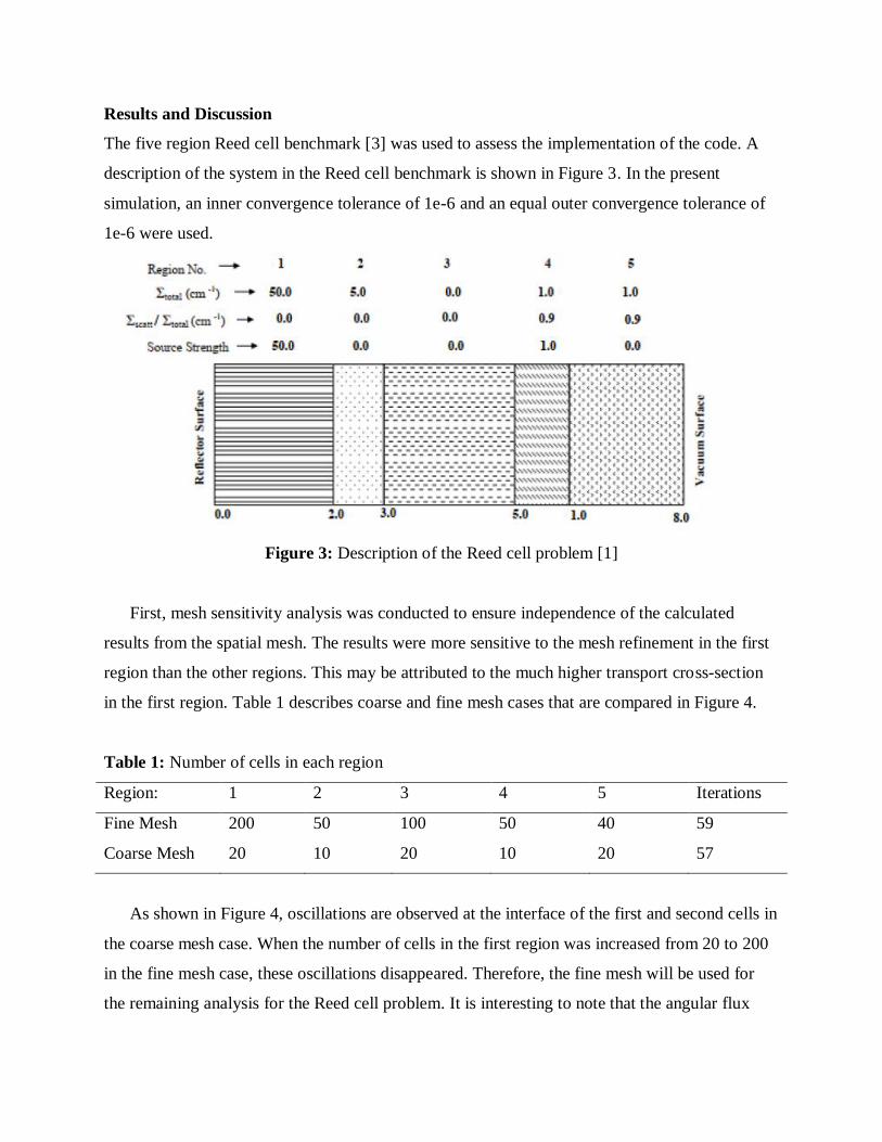
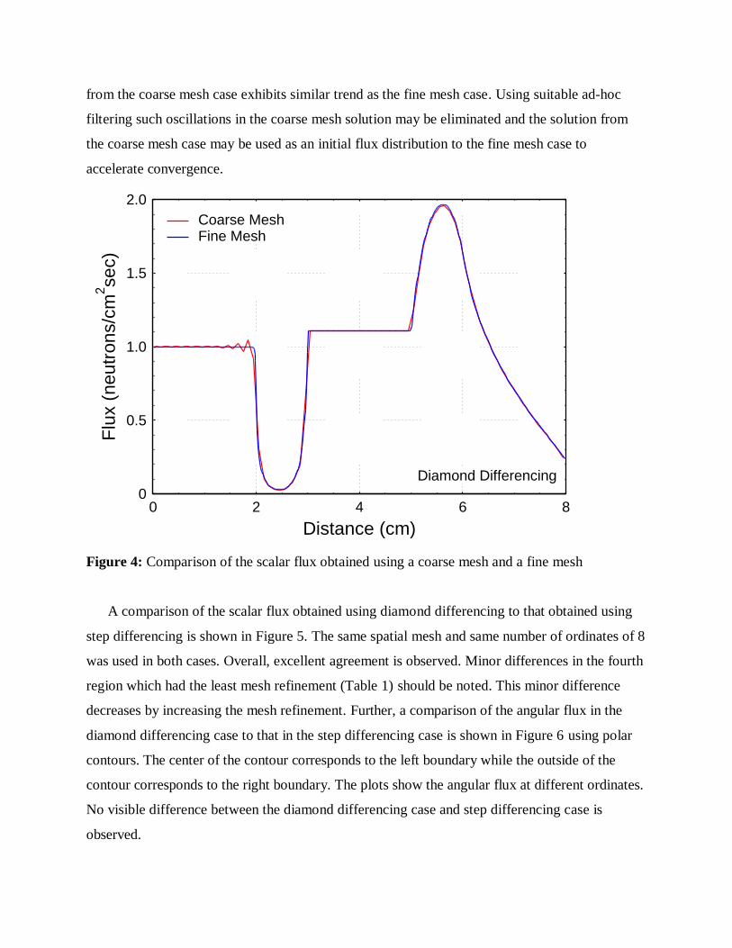
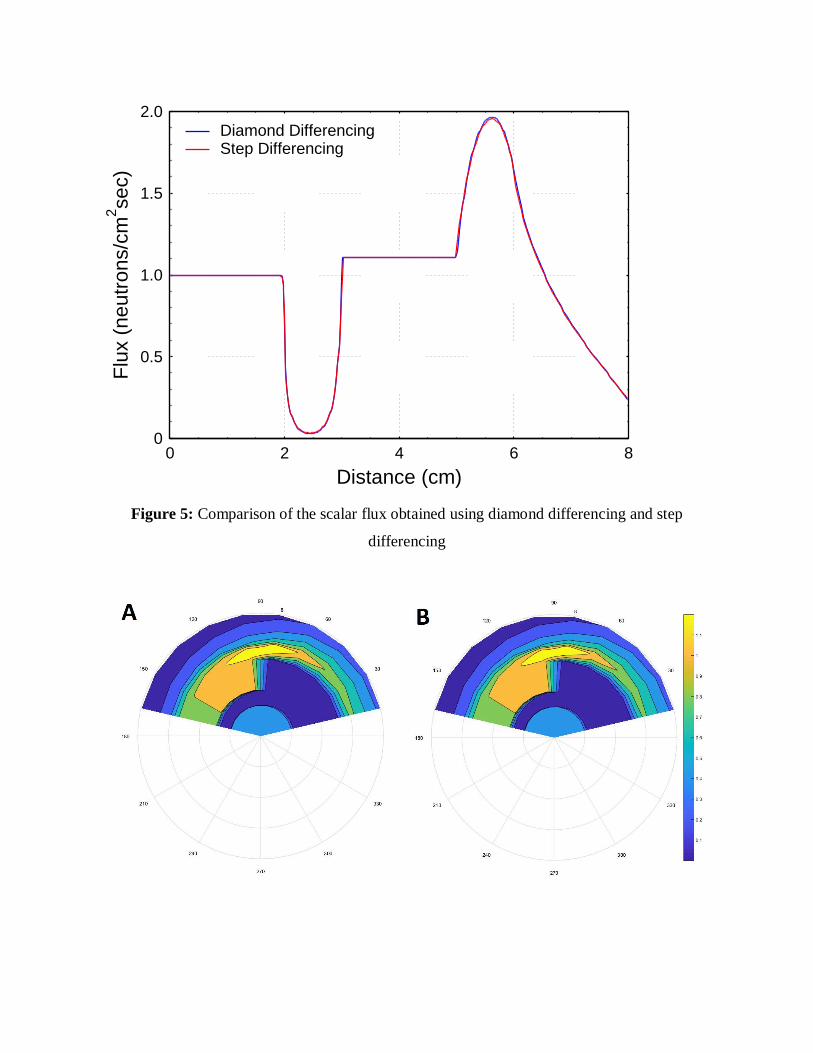
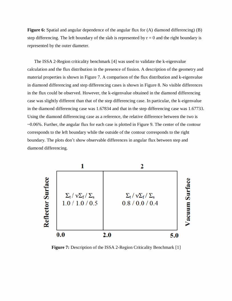
Development of a One Dimensional Sn Method Neutron Transport Solver
Khaled Talaat
NE 610 Project Report
Abstract
The present report describes the development of a one dimensional, one group neutron transport
solver. The code implements the discrete ordinates method for angular discretization. The
weighted diamond difference closure is implemented to relate the angular flux at cell centers to
that at the faces in spatial discretization. The code supports multiple regions with volume sources
and fission sources. Both albedo and incident source boundary conditions are supported. The
Reed cell benchmark and the two region criticality benchmark are used to assess the results.
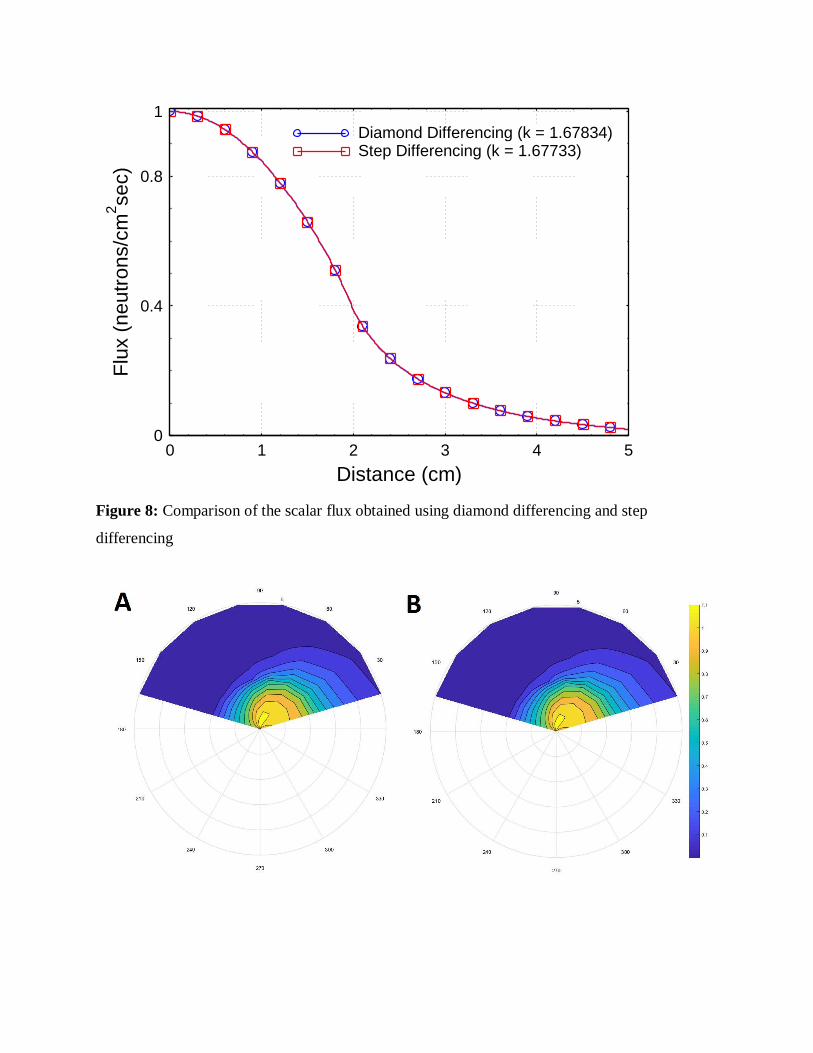
Excellent agreement is observed between the results obtained from the code and the benchmarks
using diamond differencing and step differencing. Using step differencing, a 0.06% difference is
observed in k compared to the criticality benchmark, while that of diamond differencing is
within 0.003%.
Introduction
Accurate prediction of the neutron flux distribution in a medium is essential for reactor
applications, shielding, and medical physics. The neutron transport equation governs the
transport of neutrons in media under the assumption that the neutron density is large enough for
the neutron flux to be described as a continuum but small enough for neutron-neutron collisions
to be negligible. Under the transport equation, neutrons are treated as non-decaying, point
classical particles with collisions defined by 2 body localized events. Neutrons are assumed to
have no memory of past collisions. Additionally, in reactor applications, short-timescale neutron
effects on the medium are ignored.
The neutron transport equation exists in two forms: integro-differential form and integral
form. Analytical solutions of the neutron transport equation are limited to simple cases with very
simple geometries. Practical cases of interest necessitate the use of numerical methods which
rely on discretization in space, angle, and energy. For the results to be consistent and comparable
to other work, independence of the discretization must be established within an acceptable
tolerance. However, grid independence and convergence don’t guarantee accuracy of the results.
Accuracy of the results depends on the numerical schemes used in the calculations and the order
of error associated with such schemes.
In addition to spatial discretization typical in most applications, the neutron transport
equation requires careful treatment of the angle. Various methods have been developed such as
the collision probability method, discrete ordinates method (Sn), spherical harmonics method
(Pn), and the method of characteristics (MOC). The collision probability method solves the
integral form of the transport equation and is useful when the scattering can be approximated as
isotropic. It has the ability to handle complex geometry. It, however, requires the inversion of a
large, dense matrix which can be computationally prohibiitive for large systems [1]. The discrete
ordinates method, which is discussed in more technical detail later, is often used for the integro-
differential form of the transport equation and can easily handle anisotropic scattering. It is,
however, difficult to apply to irregular geometries [1]. The method of characteristics is similar
to the Sn method but can handle complicated geometry through ray tracing to determine the
intercepts [1]. Low-order Sn method also suffers ray effects due to the inability of low-order Sn
quadrature to integrate accurately over the angular flux. The Pn method was developed to
remedy this problem [2] . It expands the angular flux in terms of orthogonal polynomials.such as
legendre polynomials and spherical harmonics as shown in Equations 1 and 2. Sn method based
codes can easily be transformed into Pn-1 codes with no fundamental changes to the main
iteration or grid sweeping [2].
𝜓𝑛(𝑧) = ∫ 𝑑𝑢 𝑃𝑛(𝜇)𝜓(𝑧, 𝜇)1
−1
(1)
𝑛+1
2𝑛+1
∂ψn+1 (𝑧)
∂z+
𝑛
2𝑛+1
∂ψn−1 (𝑧)
∂z+ (Σ𝑡 − Σ𝑠,𝑛)𝜓𝑛(𝑧) = 𝜈Σ𝑓𝜓𝑜(𝑧)𝛿𝑛,0 + 𝑆𝑛(𝑧)
(2)
The objective of the present project is to develop and benchmark a one dimensional, one
group Sn method neutron transport solver. The solver should allow for multiple regions to be
defined in a slab geometry with arbitrary mesh refinement in each region. Further, the solver
should support volumetric sources, fission sources, and albedo and incident source boundary
conditions.
Methodology
The neutron transport equation governs the transport of neutrons in the system. A particularly
useful quantity for reactor design and shielding problems is the angular flux. The angular flux,
𝜓(𝑟, 𝐸, Ω, 𝑡), is the product of the neutron density at a particular point in the phase space and the velocity
of the neutrons. Unlike the scalar flux, it preserves information on the direction that the neutrons are
traveling. The angular flux can be obtained by solving the neutron transport equation (Equation 3).
1
𝑣
∂ψ(r,E,Ω,t)
∂t + Ω. ∇𝜓(𝑟, 𝐸, Ω, 𝑡) + Σ𝑡𝜓(𝑟, 𝐸, Ω, 𝑡) = ∫ 𝑑𝐸′ ∫ 𝑑Ω′
4πΣ𝑠(𝐸′ →
∞
0
𝐸; Ω′. Ω)𝜓(𝑟, 𝐸′, Ω′, 𝑡) + 𝑥(𝐸)
4𝜋∫ 𝑑𝐸′∞
0∫ 𝑑Ω′
4π𝜈(𝐸′)Σ𝑓(𝐸′)𝜓(𝑟, 𝐸′, Ω, 𝑡) +
𝑆(𝑟, 𝐸, Ω, 𝑡)
(3)
The direction dependent scattering kernel can be expanded in terms of Legendre polynomials and a
direction independent scattering kernel (Equation 4). For most practical applications, a finite L can
accurately characerize the original scattering kernel.
Σ𝑠(𝐸′ → 𝐸; Ω′. Ω) = Σ𝑠(𝐸′ → 𝐸; μ0) = ∑2𝑙 + 1
4πΣs,l𝑃𝑙(μ0)
𝐿=∞
𝑙=0
(4)
From the orthogonality of Legendre polynomials, we get that:
Σ𝑠,𝑙(𝐸′ → 𝐸; μ0) =1
2Σ𝑠(𝐸′ → 𝐸) ∫ dμ0
1
−1
𝑃𝑙(μ0) (5)
The relationship in Equation 5 can be used to obtain the angle independent scattering kernel.
Using Equation 4 and reducing Equation 3 to a 1D slab case we get Equation 6.
𝜇∂ψ(z,μ)
∂z+ Σ𝑡(𝑧)ψ(z, μ) = ∑
2𝑙+1
2Σs,l𝑃𝑙(𝜇) ∫ 𝑑𝑢′𝑝𝑙(𝜇′)ψ(z, μ′) +
1
−1∞𝑙=0
𝜈Σ𝑓
2𝑘∫ 𝑑𝑢′ψ(z, μ′) +
𝑄(𝑧)
2
1
−1
(6)
The boundary conditions can be written in general (combined) form as in Equations 7 and 8. The
combined form can be reduced to incident source or reflection forms by adjusting the
parameters.
ψ(0, μ) = ΓL(μ) + 𝛾 ψ(0, −μ)𝑤ℎ𝑒𝑟𝑒 0 < μ ≤ 1 and 0 ≤ 𝛾 ≤ 1 (7)
ψ(L, μ) = ΓR(μ) + 𝛾 ψ(L, −μ)𝑤ℎ𝑒𝑟𝑒 − 1 ≤ μ < 0 and 0 ≤ 𝛾 ≤ 1 (8)
Up to this point, the discussion has been restricted to transport theory. The general transport
equation in Equation 3 was reduced to the one dimensional form with Legendre expansion of the
scattering kernel in Equation 6. Now we need to reformulate Equation 6 into a form that can be
implemented numerically. To achieve this, we need to discretize space, angle, and numerically
evaluate the integrals using numerical integration quadrature. The continuous integral
representing the scalar flux in Equation 6 could be written and evaluated as a discrete integral
using Equation 9. By careful choice of the angles and weights, the scalar flux can be evaluated
exactly to a polynomial fit order of 2N-1 using Gaussian quadrature. The integration points, xi,
are the roots of the Legendre polynomials. The weights of the Gauss-Legendre quadrature can be
calculated from these roots as in Equation 10. The angular discretization is, therefore, not
arbitrary but dictated by the integration points, xi.
𝜙(𝑧) = ∫ 𝑑𝑢′ψ(z, μ′) = ∑ 𝑤𝑗𝜓𝑗(𝑧)
𝑁
𝑗=1
1
−1
(9)
𝑤𝑖 =2
(1 − 𝑥𝑖2)[𝑃𝑛
′(𝑥𝑖)]2
(10)
Finally, the discretization in angle and the integration quadrature could be introduced into
Equation 6 to obtain the discrete ordinate (Sn) transport equation for a one dimensional slab
(Equation 11). This is the equation that is solved in the present project.
𝜇𝑛∂𝜓𝑛
∂z+ Σ𝑡(𝑧)𝜓𝑛(𝑧) = ∑
2𝑙+1
2
𝐿𝑙=0 Σs,l(𝑧)𝑝𝑙(𝜇𝑛) ∑ 𝑤𝑗𝑝𝑙(𝜇𝑗)𝜓𝑗(𝑧) +𝑛
𝑗=1
𝜈Σ𝑓(𝑧)
2𝑘∑ 𝑤𝑗𝜓𝑗(𝑧) +
𝑆𝑛(𝑧)
2
𝑁𝑗=1
(11)
The outer iteration scheme implemented in the current project is described in Figure 1. Initially,
the scalar flux is assumed to be uniform throughout the slab and of unity magnitude. The fission
term is calculated and fed into the inner source iteration which is described in detail in Figure 2.
The k-eigenvalue is then evaluated from the ratio of the volume integral of the fission term in the
current iteration, 𝜈Σ𝑓(𝑧)𝜙(𝑧), to that in the previous iteration. The scalar flux is then updated
and a mass balance check is done. The root mean square difference in the scalar flux in the
present iteration and that of the previous iteration is calculated to obtain the L2 error. Two
tolerances are specified by the user: an inner convergence tolerance for the inner source iteration
and an outer convergence tolerance for the outer iteration.
Figure 1: Description of the outer iteration scheme.
Figure 2: Description of the inner iteration scheme. (A) Pseudocode for forward sweep, (B)
Pseudocode for backward sweep, (C) Remainder of the steps in inner iteration
A pseudocode for the inner iteration scheme is shown in Figure 2. The inner iteration
consists of three main parts. In the first part, a forward sweep is employed to calculate the
angular flux for positive valued ordinates. The sweep starts at the left boundary where the
boundary condition is specified and described in general form as in Equation 12. The general
form can be reduced depending on the physical situation (e.g. 𝛾 = 0 if boundary is non-
reflecting). Using the value at the left face and the weighted diamond difference closure in
Equation 13, the angular flux can be evaluated at the cell center as in Equation 14. The weighted
diamond difference closure can be used to obtain the angular flux value at the right face as in
Equation 13 (forward march).
ψ(0, 𝜇𝑛) = ΓL(𝜇𝑛) + 𝛾 ψ(0, 𝜇𝑁−𝑛+1)
𝑤ℎ𝑒𝑟𝑒 0 < 𝜇𝑛 ≤ 1, and 0 ≤ 𝛾 ≤ 1
n =𝑁
2+ 1,
N
2+ 2, … , N
(12)
𝜓𝑖+
12
,𝑛=
1
1 − 𝛼𝜓𝑖,𝑛 −
𝛼
1 − 𝛼𝜓
𝑖−12
,𝑛
(13)
𝜓𝑖,𝑛 = (1 + ((1 − α)Σ𝑡,𝑖Δ𝑧𝑖
|𝜇𝑛|))
−1
(𝜓𝑖−
12
,𝑛 +
(1 − α)Δ𝑧𝑖𝑞𝑖,𝑛
|𝜇𝑛|)
(14)
Similarly a backward sweep described in Eqs. 15-17 is conducted to obtain the angular
flux at negative valued ordinates. After calculating the angular flux, the scattering term in the
right hand side of Equation 11 could be updated. The scalar flux can be calculated from Equation
9 and the root mean square difference could be evaluated as discussed earlier and compared to
the inner source iteration convergence tolerance.
ψ(L, 𝜇𝑛) = ΓR(𝜇𝑛) + 𝛾 ψ(L, 𝜇𝑁−𝑛+1) 𝑤ℎ𝑒𝑟𝑒 − 1 ≤ 𝜇𝑛 < 0 and 0 ≤ 𝛾 ≤ 1
n = 1, 2, . . ,𝑁
2
(15)
𝜓𝑖−
12
,𝑛=
1
1 − 𝛼𝜓𝑖,𝑛 −
𝛼
1 − 𝛼𝜓
𝑖+12
,𝑛
(16)
𝜓𝑖,𝑛 = (1 + ((1 − α)Σ𝑡,𝑖Δ𝑧𝑖
|𝜇𝑛|))
−1
(𝜓𝑖+
12
,𝑛 +
(1 − α)Δ𝑧𝑖𝑞𝑖,𝑛
|𝜇𝑛|)
(17)
Global Mass Balance
To ensure proper implementation, a global mass balance check is conducted. The 1D slab
transport equation shown in Equation 6 is first integrated over all angles to obtain Equation 18.
∂𝐽(𝑧)
∂z+ Σ𝑡(𝑧)𝜙(𝑧)
= ∫ 𝑑𝑢 ∑2𝑙 + 1
2
𝐿
𝑙=0
Σs,l(𝑧)𝑝𝑙(𝜇𝑛) ∑ 𝑤𝑗𝑝𝑙(𝜇𝑗)𝜓𝑗(𝑧)
𝑛
𝑗=1
1
−1
+𝜈Σ𝑓(𝑧)
𝑘𝜙(𝑧) + 𝑆(𝑧)
(18)
Second, Equation 18 is integrated over the length of the slab to obtain Equation 19 which can be
expressed in symbolic form in Equation 20.
𝐽(𝑧𝑅) − 𝐽(𝑧𝐿) + ∫ Σ𝑡(𝑧)𝜙(𝑧)𝑑𝑧𝑧𝑅
𝑧𝐿
= ∫ 𝑑𝑧 ∫ 𝑑𝑢 ∑2𝑙 + 1
2
𝐿
𝑙=0
Σs,l(𝑧)𝑝𝑙(𝜇𝑛) ∑ 𝑤𝑗𝑝𝑙(𝜇𝑗)𝜓𝑗(𝑧)
𝑛
𝑗=1
1
−1
𝑧𝑅
𝑧𝐿
+ ∫𝜈Σ𝑓(𝑧)
𝑘𝜙(𝑧)𝑑𝑧
𝑧𝑅
𝑧𝐿
+ ∫ 𝑆(𝑧)𝑑𝑧𝑧𝑅
𝑧𝐿
(19)
𝐿𝑅 + 𝐿𝐿 + 𝑇 = 𝐽−(𝑧𝑅) + 𝐽+(𝑧𝐿) + 𝑆 + 𝐹 + 𝑆𝑟 (20)
The incident boundary source and the leakage terms in Equation 20 can be evaluated using
Equations 21 and 22.
𝐽+(𝑧𝐿) = 𝑎𝑏𝑠( ∑ 𝑤𝑛𝜇𝑛𝜓0,𝑛 ) 𝑎𝑛𝑑 𝐽−(𝑧𝑅) = 𝑎𝑏𝑠(∑ 𝑤𝑛𝜇𝑛𝜓𝐼,𝑛
𝑁2
𝑛=1
𝑁
𝑛=𝑁2
+1
)
(21)
𝐿𝐿 = 𝑎𝑏𝑠( ∑ 𝑤𝑛𝜇𝑛𝜓0,𝑛 )
𝑁2
𝑛=1
𝑎𝑛𝑑 𝐿𝑅 = 𝑎𝑏𝑠( ∑ 𝑤𝑛𝜇𝑛𝜓𝐼,𝑛
𝑁
𝑛=𝑁2
+1
)
(22)
The boundary terms only involve angular integration. The transport, fission, and scattering terms
involve integration over the slab. This integration is demonstrated in Equation 23 for the
transport term.
𝑇 = ∫ Σ𝑡(𝑧)𝜙(𝑧)𝑑𝑧𝑧𝑅
𝑧𝐿
= ∑ Σ𝑡,𝑖
𝐼
𝑖=1
𝜙𝑖Δ𝑧𝑖
(23)
The scattering term involves multiple integrations over angle and space as shown in Equation 24.
No simplifications were made to the scattering term to ensure applicability of the mass balance
check in isotropic and anisotropic scattering conditions.
∫ 𝑑𝑢 ∑2𝑙 + 1
2
𝐿
𝑙=0
Σs,l(𝑧)𝑝𝑙(𝜇𝑛) ∑ 𝑤𝑗𝑝𝑙(𝜇𝑗)𝜓𝑗(𝑧)
𝑛
𝑗=1
1
−1
= ∑ 𝑤𝑛
𝑛
𝑛=1
∑2𝑙 + 1
2
𝐿
𝑙=0
Σs,l(𝑧)𝑝𝑙(𝜇𝑛) ∑ 𝑤𝑗𝑝𝑙(𝜇𝑗)𝜓𝑗(𝑧)
𝑛
𝑗=1
(24)
The present project has been implemented in C++ and has made use of the equations
described in this section. Multi-region problems with fission and volumetric sources are
supported. Both albedo and incident source boundary conditions can be used. The code has a
flexible input file structure for geometry, nuclear data, and system configuration specification.
The input structure is described in the software manual accompanying the code.
Results and Discussion
The five region Reed cell benchmark [3] was used to assess the implementation of the code. A
description of the system in the Reed cell benchmark is shown in Figure 3. In the present
simulation, an inner convergence tolerance of 1e-6 and an equal outer convergence tolerance of
1e-6 were used.
Figure 3: Description of the Reed cell problem [1]
First, mesh sensitivity analysis was conducted to ensure independence of the calculated
results from the spatial mesh. The results were more sensitive to the mesh refinement in the first
region than the other regions. This may be attributed to the much higher transport cross-section
in the first region. Table 1 describes coarse and fine mesh cases that are compared in Figure 4.
Table 1: Number of cells in each region
Region: 1 2 3 4 5 Iterations
Fine Mesh 200 50 100 50 40 59
Coarse Mesh 20 10 20 10 20 57
As shown in Figure 4, oscillations are observed at the interface of the first and second cells in
the coarse mesh case. When the number of cells in the first region was increased from 20 to 200
in the fine mesh case, these oscillations disappeared. Therefore, the fine mesh will be used for
the remaining analysis for the Reed cell problem. It is interesting to note that the angular flux
from the coarse mesh case exhibits similar trend as the fine mesh case. Using suitable ad-hoc
filtering such oscillations in the coarse mesh solution may be eliminated and the solution from
the coarse mesh case may be used as an initial flux distribution to the fine mesh case to
accelerate convergence.
Figure 4: Comparison of the scalar flux obtained using a coarse mesh and a fine mesh
A comparison of the scalar flux obtained using diamond differencing to that obtained using
step differencing is shown in Figure 5. The same spatial mesh and same number of ordinates of 8
was used in both cases. Overall, excellent agreement is observed. Minor differences in the fourth
region which had the least mesh refinement (Table 1) should be noted. This minor difference
decreases by increasing the mesh refinement. Further, a comparison of the angular flux in the
diamond differencing case to that in the step differencing case is shown in Figure 6 using polar
contours. The center of the contour corresponds to the left boundary while the outside of the
contour corresponds to the right boundary. The plots show the angular flux at different ordinates.
No visible difference between the diamond differencing case and step differencing case is
observed.
0
0.5
1.0
1.5
2.0
0 2 4 6 8
Coarse MeshFine Mesh
Diamond Differencing
Distance (cm)
Flu
x (
ne
utr
on
s/c
m2se
c)
Figure 5: Comparison of the scalar flux obtained using diamond differencing and step
differencing
0
0.5
1.0
1.5
2.0
0 2 4 6 8
Diamond DifferencingStep Differencing
Distance (cm)
Flu
x (
ne
utr
on
s/c
m2se
c)
Figure 6: Spatial and angular dependence of the angular flux for (A) diamond differencing) (B)
step differencing. The left boundary of the slab is represented by r = 0 and the right boundary is
represented by the outer diameter.
The ISSA 2-Region criticality benchmark [4] was used to validate the k-eigenvalue
calculation and the flux distribution in the presence of fission. A description of the geometry and
material properties is shown in Figure 7. A comparison of the flux distribution and k-eigenvalue
in diamond differencing and step differencing cases is shown in Figure 8. No visible differences
in the flux could be observed. However, the k-eigenvalue obtained in the diamond differencing
case was slightly different than that of the step differencing case. In particular, the k-eigenvalue
in the diamond differencing case was 1.67834 and that in the step differencing case was 1.67733.
Using the diamond differencing case as a reference, the relative difference between the two is
~0.06%. Further, the angular flux for each case is plotted in Figure 9. The center of the contour
corresponds to the left boundary while the outside of the contour corresponds to the right
boundary. The plots don’t show observable differences in angular flux between step and
diamond differencing.
Figure 7: Description of the ISSA 2-Region Criticality Benchmark [1]
Figure 8: Comparison of the scalar flux obtained using diamond differencing and step
differencing
0
0.4
0.8
1
0 1 2 3 4 5
Diamond Differencing (k = 1.67834)Step Differencing (k = 1.67733)
Distance (cm)
Flu
x (
ne
utr
on
s/c
m2se
c)
Figure 9: Spatial and angular dependence of the angular flux for (A) diamond differencing) (B)
step differencing. The left boundary of the slab is represented by r = 0 and the right boundary is
represented by the outer diameter.
Table 2 shows a comparison of the mass balance and iterations needed for scalar flux
convergence within 1e-6 mean square difference for the two benchmark cases. The mass balance
was observed to be sensitive to the convergence criterion used in the inner and outer iterations.
For the same convergence criterion stated above, it was observed that the step differencing case
had a slightly smaller mass balance than the diamond differencing case. However, the difference
was very small and given that only two cases were considered these observations don’t establish
statistical significance. The Reed cell case required 59 iterations while that of the ISSA
benchmark required a total of 257 inner iterations as a result of the outer fission iteration. The
smaller mass balance in the ISSA benchmark case is a result of the higher number of total inner
iterations due to the outer fission iterations.
Table 2: Comparison of mass balance and iterations needed for convergence in each cases
Case Differencing Scheme Mass Balance Iterations
Reed Cell DD 2.1918e-07 59
Reed Cell SD 2.0547e-07 59
ISSA Benchmark DD 3.0394e-09 257
ISSA Benchmark SD 2.9985e-09 256
Finally, the benchmark results can be compared to that of Deo et al [1]. Excellent agreement
with Deo et al. is observed for both the Reed Cell benchmark and the ISSA benchmark. The flux
shapes for both cases are identical. Using step differencing, a 0.06% difference is observed in k
compared to Deo et al., while that of diamond differencing is within 0.003%.
Acknowledgements
Corey Skinner (UNM) is acknowledged for providing ordinates function.
References
[1] Deo, K., Krishnani, P.D., and Modak, R.S., “Development of One-Dimensional Neutron
Transport Theory Code Based on Method of Characteristics,” BARC/2014/E/015
[2] Lewis, E.E., Miller, W.F., “Computational Methods of Neutron Transport,” Wiley-
Interscience, PP. 198-199
[3] Buchan, A. G. et. al., “Linear and Quadratic Octahedral Wavelets on the Sphere for Angular
Discretisations of the Boltzmann Transport Equation”, ANE 32 (2005) 1224–1273
[4] Issa, J.G., Riyait, N.S., Goddard, A.J.H., et al., “Multigroup Application of the Anisotropic
FEM code FELTRAN to One, Two, Three-dimensional and R-Z problems”, Prog. Nucl. Eng. 18
(1), 251–264 (1986)