Fernando de Azevedo Silva, [email protected] UNESP – São Paulo State University, Faculdade de Engenharia de Guaratinguetá, Departamento de Mecânica, Av. Dr. Ariberto Pereira da Cunha, 333, Pedregulho, 12.516-410, Guaratinguetá, SP, Brasil. Abstract: The stamping is a process of mechanical forming very used in the industry by facilitating the obtaining of
products with several formats, good mechanical properties and finishes or semi-finishes. The computational simulation
using the finite elements method has shown a great importance in the lasts years. Make a parametric program means,
to develop a procedure that builds a model in function of its parameters or variables. The parameterization in ANSYS
uses the programming language APDL (Ansys Parametric Design Language), that is a language dedicated to ANSYS,
that similar with other language, the FORTRAN with the addition of specific commands. When makes a parametric
program it happens a drastic decrease in the necessary time to define the variables of the stamping process and the
The stamping of sheets is a process of mechanical forming very used in the industry by facilitating the obtaining of finishes or semi-finishes products and relative complexity.
The use of programs of computational simulation, in the forming of sheets, has show a great increase in the last decade, with prominence for programs that use the finite elements method, becoming an important tool in the optimization the real processes.
The finite elements method considers the structure divided in parts or elements that are not infinitesimal, united to each other in nodes points, where they are supposed concentrated whole the connection forces among the elements. The solicitations and deformations concentrated in the nodes. The elastic and mechanical behavior of each element can have such simple mathematical expression with relationship to the one of the infinitesimal elements of the classic solution. The composition of those elements of finite size, to build the considered structure, gives place easily to a system of equations calculated by matrix way.
This work has the objective of elaborating a parametric program that has as purpose: to activate, to automate and to turn more accessible the construction of simulation models of the cylindrical cups stamping process, using the finite elements method, because its construction in a manual way is delayed, and very difficult.
The creation of the parametric program is accomplished automatically by software made in DELPHI. The input data of the software are the parameters of the stamping process and it generates, automatically, a parametric program in APDL language (Ansys Parametric Design Language), of the type " * .txt ", and this should be loaded in the program ANSYS, that will make the construction of the model in an automatic way. 2. PARAMETRIC MODELING
The parametric modeling consists of elaborating a computational program that when executed in the ambient
of the analysis software, in this case ANSYS build a model leaving of predefined parameters. The construction of a model of finite elements consists of the making the geometry, the mesh, the application of the loads and displacement conditions and the solution of the model.
The construction of a parametric program in ANSYS is accomplished being used a language of denominated special programming APDL. This programming language has as base another language, FORTRAN. The parametric is written in some text editor, ex. notepad.
After the construction of the parametric program it will be loaded it in the software ANSYS, for this, must use the sequence Utility Menu > File> Read input from, a Browser will be opened contends the location of the file with the parametric program. ANSYS will read and load the parametric automatically, not being necessary any type of the user's intervention.
The construction of a parametric program can be accomplished following some steps that are:
• The manual modeling of the simulation: in this step should be build the model in a manual way, with use the commands and menus of ANSYS, usually.
• Location of the file with extension " * .log ": this file should be located and after save it with extension " * .txt. This file contains the command lines used in the construction of the model.
• Identification the variables of the model: in this step should be identify the variables of the model, ex.: geometry variables, properties of the used material, the used element, among another. These variables will be the parameters of the model.
• Insert equations and programming routines: could be used equations to define some variables ex.: the geometry, the loads and displacements, etc. Can be used programming routines with APDL language ex.: comparison of variables with the command " IF THEN ", looping generation with the command "DO", and others specific commands. The Figure 1 shows a simplified flowchart contends the necessary stages to build a parametric program. In this parametric program were used the elements VISCO107 for the sheet and a rigid element with just a
superficial mesh for punch, die and blank-holder.
Figure 1 – Steps by build of the parametric model.
The VISCO107 is an element used for 3D modeling of the solid structures. The element is defined by eight
nodes with three degrees of freedom each node. The use of this element needs the use procedures of incremental solutions, because is applied to simulation of nonlinear behavior.
In the stamping process, the deformations and failures happen mainly in the sheet, the tools was considered a rigid body being just applied a superficial mesh where it will happen the contact with the sheet, being controlled by a pilot node, where the conditions of loads and displacement of these components will be concentrated.
In this contact rigid/flexible, the element CONTA174 was use for the sheet and the element TARGE170 for the tools.
We used three pairs of contact: punch/sheet, die/sheet and blank-holder/Sheet. The Figure 2 shows the pairs of contact.
Manual build of the simulation.
Location of the file with extension " * .log " with the command lines.
Identification of the command lines that will be substituted by parameters (ex.: geometry).
Insert equations and programming routines.
Insert the parameters and adjustment of the command lines.
In the die, the displacements and rotations are impeded in all the directions. The pressure applied blank-holder
is accomplished in a uniform way. The progress of the punch is accomplished through increments of time, is that, when a new increment is
beginning the punch moves forward. With objective of activating the modeling process, was accomplished being used a model with 1/8 and
applying symmetry conditions with relationship the vertical axis. The parametric program in subject is built in an automatic way, being just necessary that the user inserts the
necessary independent parameters. These parameters are inserted through a program developed in the programming software DELPHI.
In the Figure 3 the main interface of the program developed in DELPHI is shows, in this figure is also possible to observe the input data that should be insert by the designer.
Figure 3 – Main interface of the program developed in DELPHI.
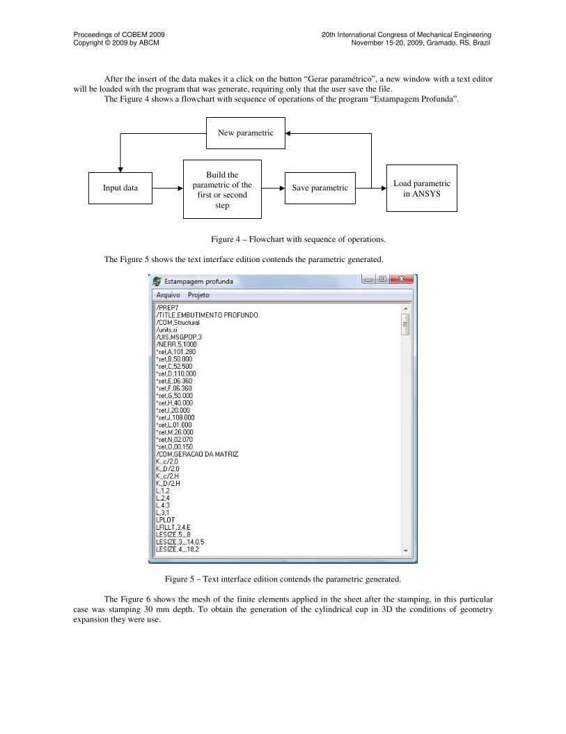
After the insert of the data makes it a click on the button “Gerar paramétrico”, a new window with a text editor will be loaded with the program that was generate, requiring only that the user save the file.
The Figure 4 shows a flowchart with sequence of operations of the program “Estampagem Profunda”.
Figure 4 – Flowchart with sequence of operations.
The Figure 5 shows the text interface edition contends the parametric generated.
Figure 5 – Text interface edition contends the parametric generated.
The Figure 6 shows the mesh of the finite elements applied in the sheet after the stamping, in this particular case was stamping 30 mm depth. To obtain the generation of the cylindrical cup in 3D the conditions of geometry expansion they were use.
Figure 6 – Mesh of the finite elements applied in the sheet after the stamping. The Figure 7 shows the modeling of the geometry components of the stamping process: punch, blank-holder,
die and sheet.
Figure 7 – Modeling of geometry components of the stamping process.
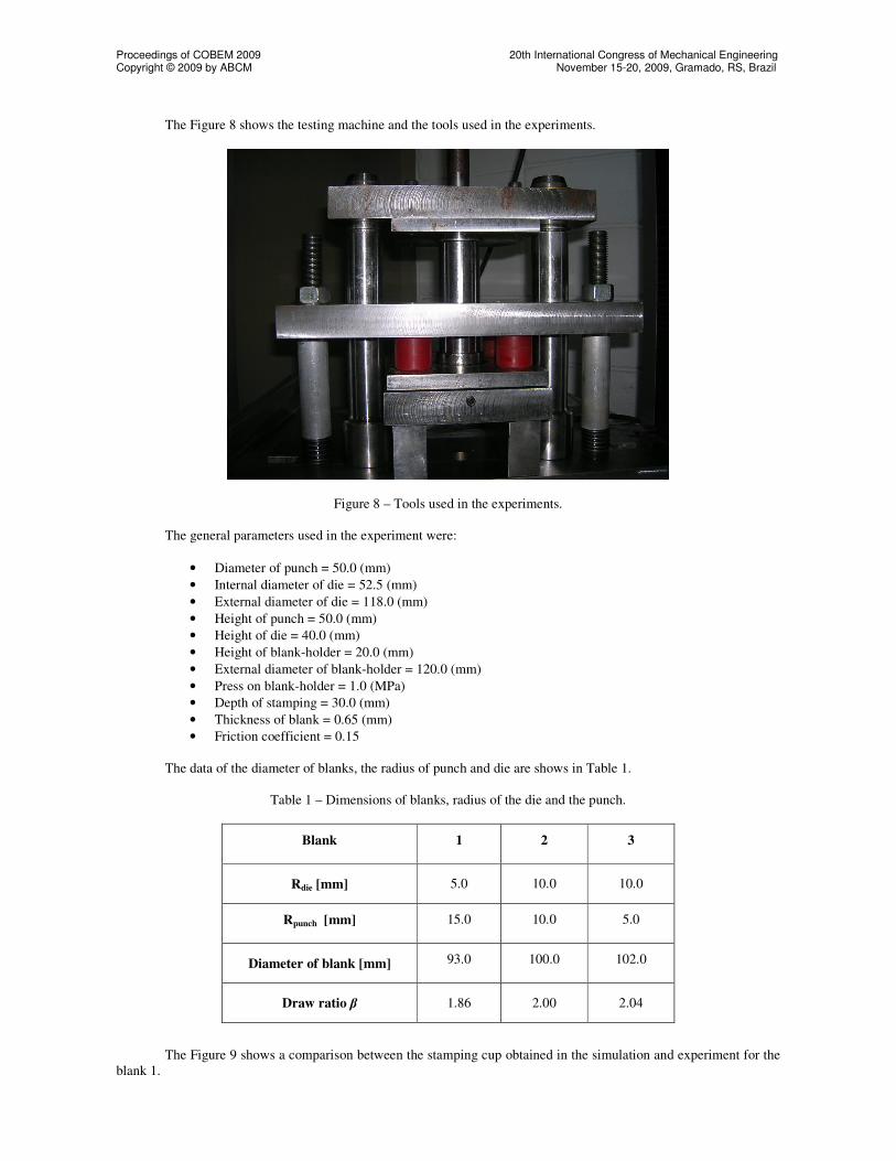
3.2. Validation of the Parametric Program
For validation of the parametric program, experiments were accomplished, and the compared data are the curves of stamping force and thickness variation of the sheet in relation to its radial position.
The chosen material, and used for the making of the experiments, it was a carbon steel sheet, with thickness of 0.65 mm, supplied by Rio Negro S.A.
Figure 9 – Comparison between the stamping cup obtained in the simulation and experiment for the blank 1. The Figure 10 shows the comparison between the stamping forces obtained in the simulation and the
experiments for the blank 1.
0
5000
10000
15000
20000
25000
30000
35000
0 5 10 15 20 25 30 35
Displacement (mm)
Fo
rce (
N)
Simulation Exp. 1 Exp. 2 Exp. 3
Figure 10 – Comparison between the stamping forces obtained in the simulation and the experiments for the blank 1.
The Figure 11 shows the comparison between the thickness variations of the sheet on its radial position, obtained in simulation and experiments for the blank 1. Radial position is the measure that begins at the center of the blank and extends until the border.
-0.100
-0.050
0.000
0.050
0.100
0.150
0 10 20 30 40 50
Radial Position (mm)
Vari
ati
on
(m
m)
Simulation Exp. 1 Exp. 2 Exp. 3
Figure 11 – Comparison between the thickness variations of the sheet on its radial position obtained in simulation and experiments for the blank 1.
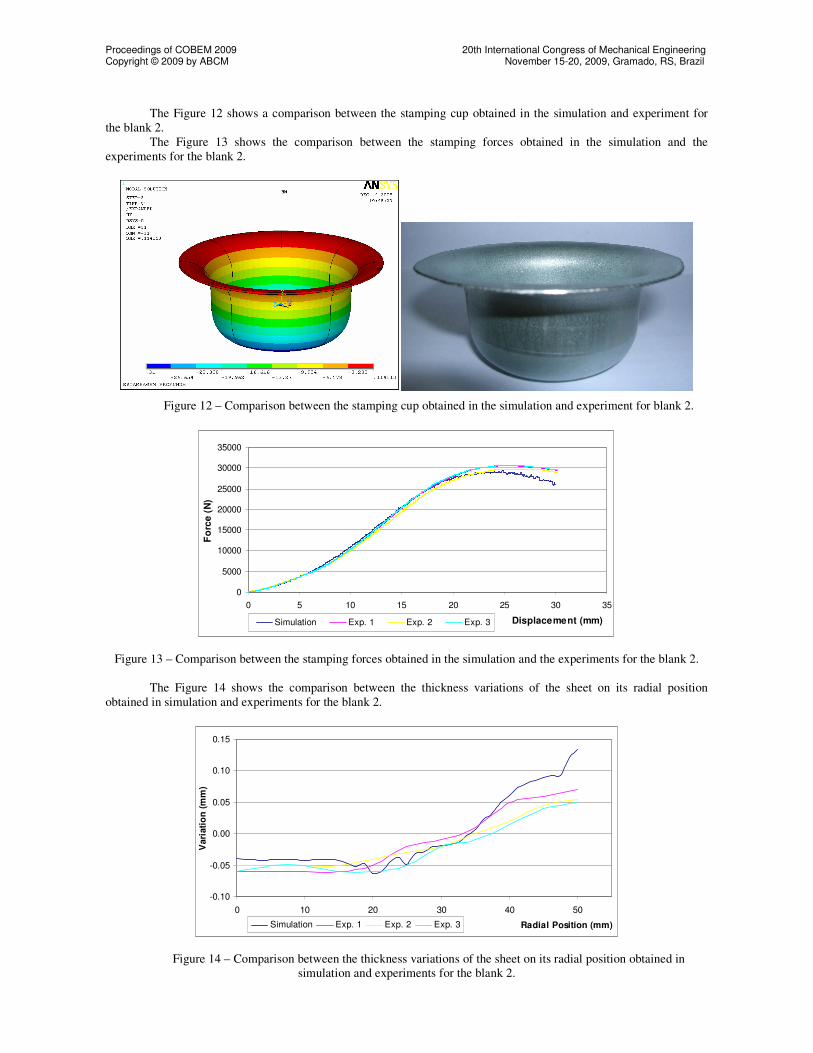
The Figure 12 shows a comparison between the stamping cup obtained in the simulation and experiment for the blank 2. The Figure 13 shows the comparison between the stamping forces obtained in the simulation and the experiments for the blank 2.
Figure 12 – Comparison between the stamping cup obtained in the simulation and experiment for blank 2.
0
5000
10000
15000
20000
25000
30000
35000
0 5 10 15 20 25 30 35
Displacement (mm)
Fo
rce
(N
)
Simulation Exp. 1 Exp. 2 Exp. 3
Figure 13 – Comparison between the stamping forces obtained in the simulation and the experiments for the blank 2. The Figure 14 shows the comparison between the thickness variations of the sheet on its radial position
obtained in simulation and experiments for the blank 2.
-0.10
-0.05
0.00
0.05
0.10
0.15
0 10 20 30 40 50
Radial Position (mm)
Vari
ati
on
(m
m)
Simulation Exp. 1 Exp. 2 Exp. 3
Figure 14 – Comparison between the thickness variations of the sheet on its radial position obtained in simulation and experiments for the blank 2.
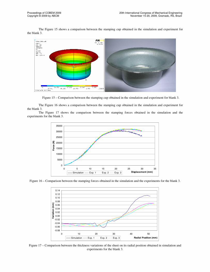
The Figure 15 shows a comparison between the stamping cup obtained in the simulation and experiment for the blank 3.
Figure 15 – Comparison between the stamping cup obtained in the simulation and experiment for blank 3.
The Figure 16 shows a comparison between the stamping cup obtained in the simulation and experiment for the blank 3. The Figure 17 shows the comparison between the stamping forces obtained in the simulation and the experiments for the blank 3.
0
5000
10000
15000
20000
25000
30000
35000
0 5 10 15 20 25 30 35
Displacement (mm)
Fo
rce (
N)
Simulation Exp. 1 Exp. 2 Exp. 3
Figure 16 – Comparison between the stamping forces obtained in the simulation and the experiments for the blank 3.
-0.08
-0.06
-0.04
-0.02
0.00
0.02
0.04
0.06
0.08
0.10
0.12
0.14
0 10 20 30 40 50
Radial Position (mm)
Vari
ati
on
(m
m)
Simulation Exp. 1 Exp. 2 Exp. 3
Figure 17 – Comparison between the thickness variations of the sheet on its radial position obtained in simulation and experiments for the blank 3.
Comparing the results, obtained with the parametric program, with the experiments, is possible to validate the
reliability of the presented program, because the values were very close. When we use the parametric program happens a drastic reduction in the necessary time to accomplish the
simulation modeling. It also turns more accessible the construction of this model, stopping being a difficult activity and not needing that the designer has great knowledge of the program ANSYS.
Analyzing the results, is observed that when decreases the radius of die and punch, it happens because an increase in the necessary force to accomplished the stamping, because they are more several work conditions and because it also happens an increase in the contact area between the blank and blank-holder, and consequently a increase the force applied by the blank-holder.
5. REFERENCES
ALVES FILHO, Avelino, 2003, “Elementos finitos: a base da tecnologia CAE”, 2nd Edition, Recife, Erica Press.
ARAGÃO, R. R., OLIVEIRA, S. A. G., 2002, “Análise da força máxima de embutimento de copos cilíndricos utilizando o método dos elementos finitos”, Proceedings of the Congresso Nacional de Engenharia Mecânica.
BARROS, E.A.R., 1999, “Delphi para Universitários”, São Paulo, Editora e Gráfica Páginas & Letras. BATHE, K. J., 1982, “Finite Elements Procedure in Engineering Analysis”, Prentice-Hall Press, Englewood
Cliffs. BUTTON, S. T., BORTOLUSSI, R., 1999, “Estudo do Processo de Embutimento Profundo de Copo pelo
Método dos Elementos Finitos”, Proceedings of the RBCM - J. of the Braz. Soc. Mechanical Engineers, Vol. XXI, no 2, pp. 355-363.
COOK, R. D., Malkus, D. S., PLESHA, M. E., 1989, “Concepts and Applications of Finite Element Analysis”, John Willey & Sons, 3th Edition.
COSTA, A. R., 2003, “Análise do Processo de Estampagem de Caixas Utilizando Elementos Finitos”. MORENO, M. E., 2002, “Development of a methodology to obtain the ideal blank shape in deep drawing process using finite element analysis”, II National Congress of Mechanical Engineering.
SCHULER, 1998, “Metal Forming Handbook”, Springer, New York, 563 p. 5. RESPONSIBILITY NOTICE
The authors are the only responsible for the printed material included in this paper.


![The Qualitative Influence of Model Parameters on the ... · (ANSYS parametric design language) [19]. Several simplifying structural assumptions were introduced: (i) rail-pads and](https://static.documents.pub/doc/80x56/60fc142c5cee6e4789635e62/the-qualitative-influence-of-model-parameters-on-the-ansys-parametric-design.jpg)


