Abstract The use of smart materials-based high speed on/off valve has exhibited the potential to replace traditional servo and proportional
valves in fluid power systems. In this paper, a novel pneumatic high speed on/off valve driven by a piezoelectric stack actuator is developed and its dynamics are studied. For an upstream gauge pressure of 0.5 MPa, the valve exhibited a large flow rate of up to 86 L/min. Furthermore, to study the ability of this novel high speed on/off valve to be applied in closed-loop control systems, a real-time position control system is realized using a PID controller. In order to prove its feasibility and effectiveness, a number of closed-loop trajectory tracking experiments are conducted on a pneumatic cylinder. The system is proved feasible and the results demonstrate good tracking performance.
High-speed on/off valves (also known as digital valves) are one of the fundamental components in the applications of digital fluid power. They have been researched over the years and demonstrated good characteristics, such as high-precision control, high reliability, pollution-proof and low cost [1, 2]. A number of researchers have highlighted the potential of on/off valves to replace servo/proportional valves [3, 4]. In order to use discrete on/off valves instead of continuously acting tradi-tional valves and obtain similar proportional characteristics, pulse width modulation (PWM) techniques are used. Apply-ing a PWM signal as the control input to a switching valve makes it on and off successively; as a result, discrete packets of fluid mass are delivered to the actuator as the valve is either completely open or completely closed. To achieve continuous-like flow, the valve is switched at high frequency. Typical examples of the applications of PWM driven on/off valves can be found in adaptive braking systems (ABS) [5], fuel injectors [6], and motion control of cylinders [7-9]. Originally devel-oped high speed on/off valves used solenoid-based actuators; however, the use of solenoids has some drawbacks, such as the delays in the response time owing to the delay of the elec-trical signal in the coil, and the reduction of the response
speed due to the high flow forces in the valve [10]. To over-come aforementioned drawbacks, different approaches such as the improvement of control electronics and structure of the solenoids [11-14]; or the use of smart materials as the driving actuators were proposed [15-18]. The results for the latter approach are promising; however, most studies focused on developing hydraulic high speed on/off valve; relatively few studies have been conducted on pneumatic ones. Matti Lin-jama (one of the pioneers of digital fluid power) expressed a similar observation that, one surprising fact is that digital prin-ciples are not studied a lot in pneumatics where they should offer similar advantages [19].
Most of the researchers who studied the possibility of using high speed on/off valves instead of traditional valves to con-trol servo-pneumatic systems employed multiple high speed on/off valves. For instance, Ahn et al. proposed a novel modi-fied pulse-width modulation valve pulsing algorithm that em-ploys eight high speed on/off valves to control a rod-less cyl-inder and the position control was successfully implemented [9]. Laib et al. presented a control system that uses an aver-aged state model and sliding mode observer to control a pneumatic actuator using four solenoid on/off valves. This observer was validated experimentally in a closed loop posi-tion tracking system [20]. Also, Najjari et al. presented a posi-tion controller for a double-acting cylinder. The system em-ploys four on/off valves and a classical PID controller opti-mized by genetic algorithm [21]. Fawaza et al. investigated
2748 N. Bruno et al. / Journal of Mechanical Science and Technology 33 (6) (2019) 2747~2759
the ability of a fuzzy PI controller to cope with the non-linearity introduced by the four on/off valves operating in a highly non-linear pneumatic system [22]. The controller per-formance was tested with sinusoidal, triangular and saw tooth reference wave inputs at a frequency of 0.1 Hz and results were satisfactory.
In this study, a novel structure of a pneumatic high speed on/off valve directly driven by a piezoelectric stack actuator is constructed. Its dynamics are mathematically and experimen-tally studied to determine its flow characteristics.
Unlike most of previous researches, which employed multi-ple high speed/off valves to replace traditional servo and pro-portional valves, this new control system employs a single high speed on/off valve in combination with a directional con-trol valve to control the position of a pneumatic cylinder.
Taking into consideration the working principle of piezo-electric materials and the properties of compressed air, a new structure of a high speed on/off valve is designed. Its mathe-matical model is established based on the designed structure; and Matlab/Simulink is used to build a simulation model. Furthermore, experimental studies are conducted on the manu-factured prototype of the high speed on/off valve to investi-gate its flow characteristics. After evaluating the flow charac-teristics, a closed-loop system is proposed to realize real-time position control of a pneumatic actuator using a combination of PWM signal and a PID controller. The tracking perform-ance of the proposed real-time position control system is dem-onstrated and interpreted.
2. Structure and working principle of the valve
2.1 Structure of the valve
The structure and photograph of the designed high speed on/off valve driven by a piezoelectric stack actuator are shown in Fig. 1. It is a normally-closed (NC) type of valve, which mainly consists of a piezoelectric stack (size: 14 mm× 14 mm×40 mm), a mobile plate, and the valve body. The pie-zoelectric stack actuator drives the mobile plate, which re-stricts or allows the air flow through the valve. Since the pie-zoelectric stack actuator can only provide pushing force, when the actuator is de-energized the mobile plate is returned to the initial position by a set of disc springs acting against it.
The typical expansion of a piezoelectric stack is within 0.075 % to 0.150 %. In some applications, displacement am-plification mechanisms are used to amplify the stroke of the piezoelectric material; however, displacement amplification is a trade-off between large displacement and force [23]; thus, in this work, a direct drive method was selected in order to pre-serve high dynamics of the piezoelectric stack. At the bottom end of the actuator, an adjusting bolt was used to ensure that the output rod is in contact with the mobile plate. Another challenge of the piezoelectric stacks is that, they are highly vulnerable to tensile and lateral forces. The common practice to avoid such damage is to mechanically preload the piezo-electric stack to compensate for excessive tensile load [24];
therefore, in this design the piezoelectric stack was preloaded using another set of disc springs. In addition to that, slots were cut in the actuator’s shell to facilitate the dissipation of the heat that could be generated by the piezoelectric stack when driven at high frequency.
2.2 Working principle of the valve
Initially, the mobile plate is pushed against the valve seat by disc spring1; that contact prevents the compressed air to flow from the inlet chamber to the outlet chamber; thus, the valve is “normally closed”. When a voltage signal is applied to the piezoelectric stack actuator, the expansion of the piezoelectric stack leads to the motion of the output rod, which in return moves the mobile plate. Consequently, the air flows from the inlet chamber to the outlet. Once the applied voltage signal is switched off, the piezoelectric stack retracts and the mobile plate is returned to the initial position by disc spring1. When a PWM signal is used as the input, the valve switches between two states (on and off) at high frequency. By modulating the duty cycle of the signal, the air flow rate through the valve changes accordingly, which results in a controllable air flow.
3. Mathematical model of the valve
Based on the structure of the valve and its working principle, the mathematical model is divided into two parts: An electro-mechanical model and a fluidic model as illustrated in the block diagram in Fig. 2. The electromechanical domain repre-sents the conversion of the electrical energy into mechanical energy by the piezoelectric stack actuator. Whereas, the fluidic domain represents the conversion of the valve opening into the
Fig. 1. The designed high speed on/off valve (1. Bottom end cap, 2. Inlet chamber, 3. Spring preloading plate, 4. Disc spring1, 5. Mobile plate, 6. Outlet chamber, 7. Disc spring 2, 8. Output rod, 9. Piezoelec-tric stack, 10. Adjusting bolt). .
N. Bruno et al. / Journal of Mechanical Science and Technology 33 (6) (2019) 2747~2759 2749
corresponding air flow.
3.1 Electromechanical model
As shown in Fig. 3, the motion of the driving part of the high speed on/off valve can be modeled as a single degree of freedom system [25].
Mathematically, it is expressed as:
e v p v p 1 2 v p i o+ + ( + + ) = - ( - )m x c x k k k x F F F&& & (1)
where me denotes the equivalent mass, cp denotes the damping constant of the piezoelectric stack; kp, k1 and k2 denote the stiffness of the piezoelectric stack, the disk spring1 and the disc spring 2; respectively. Fi, Fo denote the force exerted by the compressed air to the inlet side of the mobile plate and to the outlet side, respectively. Fp denotes linear output force of the piezoelectric stack. Eq. (1) can be further derived as fol-lows [26].
1 2
( )
1( ) ( )3
( )
p r m v p v p v
up i i o o
tt
m m m x c x k k k x
k e u p A p Att
--
+ + + + + +
= -
&& & (2)
where mp, mr, mm denote the mass of the piezoelectric stack, the output rod and the mobile plate, respectively. ku denotes the scale factor between the linear output force and the input voltage. τ denotes the time constant and up denotes the input voltage signal. pi and po denote the absolute upstream stagna-
tion pressure and downstream stagnation pressure, respec-tively. Ai and Ao denote the area of the inlet side and the outlet side of the mobile plate, respectively.
As PWM signal can only have two states (high level and low level), for one period, the driving signal can be expressed as shown in Eq. (4).
on
p
TDT
= (3)
pp
p( )
0 t
V t DTu
t DT
£ìï= í >ïî (4)
where Ton denotes the “on-time”, Tp denotes the period of the signal, D denotes the duty cycle, and V denotes the amplitude of the PWM signal.
3.2 Fluidic model
The standard equation of the air mass flow rate through the valve is given in Eq. (5). This equation is based on ISO 6358 standard [27, 28].
o
ci
p bp£
( )
( )
+11 2 -1
d v i 2
12 +1 2γ
d v i o o
i i
2 +1
2 - -1
C A pRT
mC A p p p
p pRT
gg
gg
gg
gg
ìæ öïç ÷ï è øïï= í æ öæ öï æ ö æ öç ÷ç ÷ï ç ÷ ç ÷ç ÷ç ÷ï è ø è øç ÷ç ÷è øï è øî
&
oc
ibp
p>
(5)
where for a sharp edged orifice the value of
-1
c2+1
b
gg
gæ ö
= ç ÷è ø
. (6)
Cd denotes the discharge coefficient of the valve, Av denotes
the effective cross sectional area of fluid flow path, pi denotes the absolute upstream stagnation pressure of the valve, po de-notes the absolute downstream stagnation pressure of the valve, T denotes the upstream stagnation temperature, R de-notes gas constant and γ denotes the heat capacity ratio.
The critical pressure ratio bc of a pneumatic valve is the ra-tio between the downstream absolute pressure po and the up-stream absolute pressure pi at which the air velocity achieves sonic speed. When the ratio between the downstream absolute pressure po and the upstream absolute pressure pi is less than the critical pressure ratio bc of a valve, further reduction of the downstream pressure po does not increase the air mass flow as Eq. (5) indicates.
4. Simulation model of the high speed on/off valve
To theoretically analyze the characteristics of the valve, the equations mentioned in the mathematical modelling section
up
Mobile plate displacement
Airflow
Electro-mechanical
domain
Voltage signal
Fluidic domainXp Q
Fig. 2. Block diagram of the mathematical model.
kp
Cp
xv
k1
k2
Fi
me
Piezoelectric stack
up
Fp
Fo
Fig. 3. Electromechanical model representation.
2750 N. Bruno et al. / Journal of Mechanical Science and Technology 33 (6) (2019) 2747~2759
were solved numerically using MATLAB/Simulink. The complete simulation model permits the estimation of
the valve’s flowrate by specifying the driving voltage signal. Parameters of the complete model are shown in Tables 1 and 2. Using Simulink model, flow characteristics of the valve were simulated under various working conditions and driving signals
First, the effect of the frequency to the air flow was studied. The amplitude of the PWM signal was set to 80 V, the duty cycle to 60 % and the upstream gauge pressure (ps) to 0.4 MPa. In all simulations in this work, the absolute downstream pres-sure was assumed to be equal to the atmospheric pressure (0.1 MPa). The flow accumulation at frequencies of 5 Hz, 10 Hz, 15 Hz and 20 Hz, respectively, were compared and the results are shown in Fig. 4.
As it can be seen in Fig. 4, in addition to leading to a more quasi-continuous flow, increasing the frequency increases the resolution of the valve’s flow regulation.
Secondly, PWM signals of different duty cycles were ap-plied to the valve’s simulation model to study how the duty cycle affects the flow. Fig. 5 shows the comparison of three different duty cycles for upstream gauge pressures of 0.2 MPa and 0.4 MPa, respectively. The frequency of the PWM signals was set to 20 Hz and the amplitude to 80 V.
As predicted, the results demonstrated that the flow rate in-creases with the increase of the duty cycle. These results af-firmed that the air flow rate through the valve could be con-trolled by modulating the duty cycle.
5. Simulation model validation
5.1 Electromechanical model validation
To experimentally validate the electromechanical model, the test bench shown in Fig. 6 was set-up and tests were con-ducted.
Table 1. Parameters of the electro-mechanical model.
Name Unit Symbol Value
Mass of the piezoelectric stack kg mp 0.062
Mass of the piston rod kg mr 0.014
Mass of the mobile plate kg mm 0.033
Damping constant of the piezoelectric stack N·s·m-1 cp 1500
Stiffness of the piezoelectric stack N·m-1 kp 0.70×10⁸
Stiffness of the disk spring 1 N·m-1 k1 1.5×10⁶
Stiffness of the disk spring 2 N·m-1 k2 1.5×10⁶
Cross section area of the inlet chamber m2 Ai 0.96×10⁻³
Cross section area of the outlet chamber m2 Ao 0.42×10⁻³
Scale factor between the linear output force and the input voltage N/V ku 57.966
The time constant s τ 5×10⁻⁵
The value of the damping constant of the piezoelectric stack [26]
Table 2. Parameters of the fluidic model.
Name Unit Symbol Value
Discharge coefficient - Cd 0.5
Gas constant J/kg·K R 288
Mass density at standard reference atmosphere kg/m3 ρ 1,185
Heat capacity ratio - γ 1.4
The absolute downstream pressure MPa po 0.1
Fig. 4. Air flow accumulation for various frequencies.
Fig. 5. The effect of the duty cycle to the air flow.
N. Bruno et al. / Journal of Mechanical Science and Technology 33 (6) (2019) 2747~2759 2751
The aim was to capture the displacement of the mobile plate for different input signals. A signal generator (RIGOL DG1022) was used to generate a PWM signal; the signal was amplified by a power amplifier (AE Techron 7224); then, applied to the valve. A laser displacement sensor (Shanghai Sixin CD5-30(A), accuracy linearity ±0.08 %) captured the displacement of the valve’s mobile plate and data were stored by the oscilloscope (GW Instek GDS-1104B). Due to the fact that the displacement of the mobile plate had to be captured using the laser displacement sensor, the bottom end cap of the valve was removed, and evidently the inlet port of the valve was not connected to the air supply; therefore, to have the same conditions in the simulation, the absolute upstream pres-sure (pi) was set to 0.1 MPa (the atmospheric pressure).
Comparison of the simulation and experimental results are shown in Fig. 7. As it can be seen in the figure, the simulation model can be used to estimate the switching of the mobile plate for different duty cycles.
5.2 Complete model validation
After validating the electromechanical model, another test bench was set-up to validate the complete model of the valve (Fig. 8). In this experiment, since complete simulation model relates the input voltage signal to the output air flow, various voltage input signals were applied to the designed high speed on/off valve and the resulting air flow rates were measured using a flow meter (Shuanghuan LZB-10WB-F). A PWM signal was generated using the signal generator; the signal was sent to the power amplifier; the power amplifier amplified the PWM signal and sent it to the valve. Simultaneously, the air compressor supplied the compressed air and a pressure regula-tor (Festo FRC-1/4-D-MIDI) was used to set the desired up-stream gauge pressure. A flowmeter captured the air flow rate downstream for each tested working conditions.
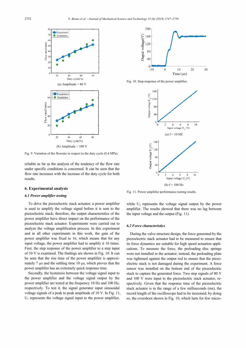
The valve was experimentally tested under various working conditions and the results were compared with the simulation results to validate it. The variation of the flow rate in respect to the duty cycle at a constant upstream pressure is shown in Fig. 9.
The discrepancies between the simulation and the experi-mental results can be explained by the fact that the simulation
model takes several assumptions into account. Some of the assumptions are that, the air in the system is an ideal gas; gas density in the valve and pipelines is uniform; the air flow process is adiabatic; no leak occurs anyway in the system; the temperature change inside the valve is negligible with respect to the temperature of the air supply; and that the supply pres-sures are constant, which are not the actual conditions during the experiment. Despite that, the developed model can be
Fig. 6. Electromechanical model validation test bench.
(a) Duty cycle = 20 %
(b) Duty cycle = 60 %
Fig. 7. Mobile plate displacement (amplitude 100 V).
Fig. 8. Photograph of the test bench of the valve's flow characteristics.
2752 N. Bruno et al. / Journal of Mechanical Science and Technology 33 (6) (2019) 2747~2759
reliable as far as the analysis of the tendency of the flow rate under specific conditions is concerned. It can be seen that the flow rate increases with the increase of the duty cycle for both results.
6. Experimental analysis
6.1 Power amplifier testing
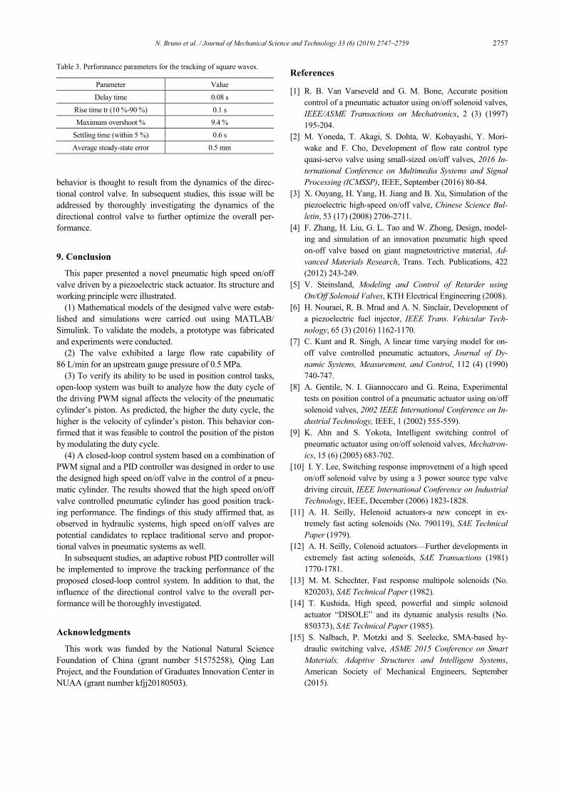
To drive the piezoelectric stack actuator, a power amplifier is used to amplify the voltage signal before it is sent to the piezoelectric stack; therefore, the output characteristics of the power amplifier have direct impact on the performance of the piezoelectric stack actuator. Experiments were carried out to analyze the voltage amplification process. In this experiment and in all other experiments in this work, the gain of the power amplifier was fixed to 16, which means that for any input voltage, the power amplifier had to amplify it 16 times. First, the step response of the power amplifier to a step input of 10 V is examined. The findings are shown in Fig. 10. It can be seen that the rise time of the power amplifier is approxi-mately 7 µs and the settling time 10 µs, which proves that the power amplifier has an extremely quick response time.
Secondly, the hysteresis between the voltage signal input to the power amplifier and the voltage signal output by the power amplifier are tested at the frequency 10 Hz and 100 Hz, respectively. To test it, the signal generator input sinusoidal voltage signals of a peak to peak amplitude of 10 V. In Fig. 11, U1 represents the voltage signal input to the power amplifier,
while U2 represents the voltage signal output by the power amplifier. The results showed that there was no lag between the input voltage and the output (Fig. 11).
6.2 Force characteristics
During the valve structure design, the force generated by the piezoelectric stack actuator had to be measured to ensure that its force dynamics are suitable for high speed actuation appli-cations. To measure the force, the preloading disc springs were not installed in the actuator; instead, the preloading plate was tightened against the output rod to ensure that the piezo-electric stack is not damaged during the experiment. A force sensor was installed on the bottom end of the piezoelectric stack to capture the generated force. Two step signals of 80 V and 100 V were input to the piezoelectric stack actuator, re-spectively. Given that the response time of the piezoelectric stack actuator is in the range of a few milliseconds (ms), the record length of the oscilloscope had to be increased; by doing so, the overshoot shown in Fig. 10, which lasts for few micro-
(a) Amplitude = 80 V
(b) Amplitude = 100 V
Fig. 9. Variation of the flowrate in respect to the duty cycle (0.4 MPa).
Fig. 10. Step-response of the power amplifier.
(a) f = 10 HZ
(b) f = 100 Hz
Fig. 11. Power amplifier performance testing results.
N. Bruno et al. / Journal of Mechanical Science and Technology 33 (6) (2019) 2747~2759 2753
seconds, could not be captured in this specific experiment due to the sample rate of the oscilloscope. The results of the ex-periment are shown in Fig. 12.
The piezoelectric stack actuator generates 900 N for a volt-age input of 80 V and 1100 N for a voltage input of 100 V. In both cases, the rise time of the force generated by the piezo-electric stack actuator is approximately 0.5 ms, which is quick enough to be applied in high speed actuation applications.
6.3 Flow characteristics
To assess and confirm the viability of the designed high speed on/off valve to be applied in motion control applications. The test bench shown in Fig. 8 was used to further test the valve. In this set of experiments, the effect of the amplitude and the duty cycle of the PWM voltage signal was studied. PWM signals with amplitudes of 80 V, 100 V and 120 V, respectively, were applied to the high speed on/off valve. The duty cycle was varied from 20 % to 80 % for each signal and the flow rate at the outlet port of the valve was measured using the flow meter. The frequency of the driving signal was set to 20 Hz. These experiments were carried out under three differ-ent upstream gauge pressures (0.2 MPa, 0.4 MPa and 0.5 MPa). The results in Fig. 13 showed that, as it had been found during the simulation-based analysis, increasing the amplitude of the PWM signal increased the flow rate. In the same way, when the duty cycle increases, the flow rate increases as well. As shown in Fig. 13(c), the valve exhibited a large flow ca-pacity of up to 86 L/min for an upstream gauge pressure of 0.5 MPa.
These findings affirmed that the flow through the valve could be regulated by modulating the duty cycle as predicted
during the simulation-based analysis.
7. Dynamics of a pneumatic cylinder controlled by
the developed valve in an open-loop system
Before designing a closed-loop system, the dynamics of an open loop system consisting of the designed valve and a dou-ble-acting pneumatic cylinder (Chaozhong pneumatic SCJ 32X125-50) were investigated. The schematic of the open-loop control system is shown in Fig. 14. The signal generator was employed to generate a PWM signal. The signal was sent to the power amplifier and the power amplifier fed the ampli-fied signal to the designed high speed on/off valve. Simulta-neously, the pressure regulator, which is part of the air service unit, was used to set the supply pressure. The designed valve was directly connected to one of the chambers of the cylinder while the other chamber was open to the atmosphere. The
Fig. 12. Force step response of the piezoelectric stack actuator.
(a) ps = 0.2 MPa
(b) ps = 0.4 MPa
(c) ps = 0.5 MPa
Fig. 13. The relationship between the duty cycle and the flow rate for different upstream gauge pressures.
2754 N. Bruno et al. / Journal of Mechanical Science and Technology 33 (6) (2019) 2747~2759
movement of the piston was captured by a rod type displace-ment sensor (GEERT HLC-175 mm, accuracy: ±0.05 %).
First, the effect of the signal’s duty cycle to the displace-ment of the piston was examined. The supply pressure was set to 0.4 MPa and the frequency of the PWM signal to 30 Hz. It can be seen from Fig. 15 (the dotted line indicates the maxi-mum displacement) that, when the duty cycle increases, the speed of the piston increases as well. There is a larger increase in the speed of the piston when the duty cycle is changed from 20 % to 50 % compared to when it is changed from 50 % to 80 %. This is due to the fact that when the duty cycle is low, the flowrate increment step-size is small; thus the speed is relatively low.
Second, the effect of the supply pressure to the displace-ment of the piston was also examined. The results are shown in Fig. 16. The speed of the piston increases with the increase of the supply pressure.
8. Closed-loop position control
After the analysis of the flow characteristics of the devel-oped high speed on/off valve and the dynamics of the pneu-matic cylinder controlled by the valve in an open-loop system, a closed loop control system was also designed as shown in Fig. 17. The closed loop system consists of a double acting
cylinder (Chaozhong pneumatic SCJ 32X125-50, bore diame-ter: 32 mm, maximum stroke 150 mm), the developed high speed on/off valve, which is used to control the air flow to the cylinder, a directional control valve (Festo MHE2-MSIH-5/2-M7-K) used to change the direction of the air flow, a dis-placement sensor (GEERT HLC-175, max stroke: 175 mm, accuracy: ±0.05 %) to transmit real-time position data to the data acquisition card (PCI 6251) and a power amplifier(AE Techron 7224) to amplify the signal before it is sent to the high speed on/off valve. Data acquired from the sensors are processed via a controller running on the host computer of an xPC environment to calculate the control signals. A PWM signal whose duty cycle is determined by the controller is sent to the high speed on/off valve to control the air flow rate and depending on the sign of the error between the desired and the actual position, a signal is sent to the directional control valve to direct the air to the proper chamber.
8.1 Controller design
The motion control strategy adopted in this work is mainly based on a combination of PWM signal and PID feedback controller. For over decades, PID controllers have been used in industrial control applications. Despite being around for a longtime, they are still applied in the majority of closed-loop
Fig. 14. Schematic diagram of the open-loop control system.
Fig. 15. Effect of the duty cycle on the piston displacement.
Fig. 16. Effect of the supply pressure to the piston displacement.
N. Bruno et al. / Journal of Mechanical Science and Technology 33 (6) (2019) 2747~2759 2755
applications. PID controller is often combined with logic, sequential functions, selectors, and simple function blocks to build the complicated automation systems [29]. In digital fluid power technology, a flow control strategy such as PWM or PFM is combined with one or multiple feedback control strategies to build a closed-loop control system. For example, Mazare M. et al. used a combination of PWM signal and a PID controller to control a pneumatic actuator using a fast switching valve [30]. Thananchai built a closed-loop system to control both the position and the force of a pneumatic artificial muscle using a combination of PWM signal and fuzzy logic controller [31].
In this work, a combination of PWM signal and a PID con-troller method is used. The proposed control system consists of two layers of controllers (Fig. 18). A logic controller and a flowrate controller. The former controls the operation of the directional control valve according to the sign of the error between the position command signal and the measured posi-tion signal, and the latter controls the switching of the high speed on/off valve by calculating the value of the duty cycle needed to eliminate the error on real-time.
Generally, the input/output relation for an ideal PID control-ler with error feedback is expressed as:
0
( )( ) ( ) ( )t
p i dde tu t K e t K e t dt K
dt= + +ò (7)
where e(t) is the error between the desired and the actual posi-tion, u(t) is the control signal, Kp, Ki and Kd are the propor-tional ,integral and derivative coefficients.
In relation to the proposed function of the PID controller in the designed closed-loop control system, Eq. (7) can be rewrit-ten as follows:
0
( )( ) ( ) ( )
t
p i d
d e tD t K e t K e t dt K
dt= + +ò (8)
where |e(t)| is the absolute value of the error between the de-sired and the actual position; D(t) is the duty cycle of the con-trol PWM signal; and Kp = 0.04, Ki = 0.01 and Kd = 0.01. These values were obtained after manually tuning the PID controller through multiple experiments that aimed at identify-ing the best parameters.
8.2 Position control results
To test the performance of the proposed control system, a number of reference trajectories were used. First, a sinusoidal trajectory with frequencies of 0.1 Hz, 0.15 Hz, 0.2 Hz, 0.5 Hz, respectively, were input to the system as the reference signal. The frequency of the control PWM signal was set to 30 Hz and the supply pressure to 0.4 MPa. Since the value of voltage output by digital pins of the xPC are 5 V (for high) and 0 V (for low), the gain of the amplifier was preset to 16 in order to obtain a PWM signal of an amplitude of 80 V.
From Figs. 19-21, it can be seen that the proposed control system possess good tracking performance. Fig. 21 shows the results for a higher frequency of 0.5 Hz. A slight increase in the error was noticed compared to lower frequencies (0.1 Hz and 0.2 Hz). Nonetheless, the tracking performance at
(a) Schematic diagram (b) Photograph Fig. 17. Experimental set-up of the proposed closed-loop control system.
Fig. 18. Schematic diagram of the control system.
2756 N. Bruno et al. / Journal of Mechanical Science and Technology 33 (6) (2019) 2747~2759
that frequency is still within an acceptable range. No phase lag or amplitude weakening occurred for any tested fre-quency.
After the performance of the control system to track sinu-soidal trajectories was analyzed, the command signal was changed to square waves. Fig. 22 shows the results for a square wave signal of 0.2 Hz and a duty cycle of 50 %.
From the results summarized in Table 3, it can be seen that the designed controller can track the reference signal with a small steady state error, minor overshoots and fast settling time. At the beginning of the motion of the piston, there is a slight delay due to the pressure build-up time during which the force of the air pressure has to overcome the dry friction force. Some oscillations are noticed before the piston settles and this
Fig. 21. Tracking performance for a reference sinusoidal signal of 0.5 Hz.
Fig. 22. Tracking performance for a square wave reference signal of 0.2 Hz.
Fig. 19. Tracking performance for a reference sinusoidal signal of 0.1 Hz.
Fig. 20. Tracking performance for a reference sinusoidal signal of 0.2 Hz.
N. Bruno et al. / Journal of Mechanical Science and Technology 33 (6) (2019) 2747~2759 2757
behavior is thought to result from the dynamics of the direc-tional control valve. In subsequent studies, this issue will be addressed by thoroughly investigating the dynamics of the directional control valve to further optimize the overall per-formance.
9. Conclusion
This paper presented a novel pneumatic high speed on/off valve driven by a piezoelectric stack actuator. Its structure and working principle were illustrated.
(1) Mathematical models of the designed valve were estab-lished and simulations were carried out using MATLAB/ Simulink. To validate the models, a prototype was fabricated and experiments were conducted.
(2) The valve exhibited a large flow rate capability of 86 L/min for an upstream gauge pressure of 0.5 MPa.
(3) To verify its ability to be used in position control tasks, open-loop system was built to analyze how the duty cycle of the driving PWM signal affects the velocity of the pneumatic cylinder’s piston. As predicted, the higher the duty cycle, the higher is the velocity of cylinder’s piston. This behavior con-firmed that it was feasible to control the position of the piston by modulating the duty cycle.
(4) A closed-loop control system based on a combination of PWM signal and a PID controller was designed in order to use the designed high speed on/off valve in the control of a pneu-matic cylinder. The results showed that the high speed on/off valve controlled pneumatic cylinder has good position track-ing performance. The findings of this study affirmed that, as observed in hydraulic systems, high speed on/off valves are potential candidates to replace traditional servo and propor-tional valves in pneumatic systems as well.
In subsequent studies, an adaptive robust PID controller will be implemented to improve the tracking performance of the proposed closed-loop control system. In addition to that, the influence of the directional control valve to the overall per-formance will be thoroughly investigated.
Acknowledgments
This work was funded by the National Natural Science Foundation of China (grant number 51575258), Qing Lan Project, and the Foundation of Graduates Innovation Center in NUAA (grant number kfjj20180503).
References
[1] R. B. Van Varseveld and G. M. Bone, Accurate position control of a pneumatic actuator using on/off solenoid valves, IEEE/ASME Transactions on Mechatronics, 2 (3) (1997) 195-204.
[2] M. Yoneda, T. Akagi, S. Dohta, W. Kobayashi, Y. Mori-wake and F. Cho, Development of flow rate control type quasi-servo valve using small-sized on/off valves, 2016 In-ternational Conference on Multimedia Systems and Signal Processing (ICMSSP), IEEE, September (2016) 80-84.
[3] X. Ouyang, H. Yang, H. Jiang and B. Xu, Simulation of the piezoelectric high-speed on/off valve, Chinese Science Bul-letin, 53 (17) (2008) 2706-2711.
[4] F. Zhang, H. Liu, G. L. Tao and W. Zhong, Design, model-ing and simulation of an innovation pneumatic high speed on-off valve based on giant magnetostrictive material, Ad-vanced Materials Research, Trans. Tech. Publications, 422 (2012) 243-249.
[5] V. Steinsland, Modeling and Control of Retarder using On/Off Solenoid Valves, KTH Electrical Engineering (2008).
[6] H. Nouraei, R. B. Mrad and A. N. Sinclair, Development of a piezoelectric fuel injector, IEEE Trans. Vehicular Tech-nology, 65 (3) (2016) 1162-1170.
[7] C. Kunt and R. Singh, A linear time varying model for on-off valve controlled pneumatic actuators, Journal of Dy-namic Systems, Measurement, and Control, 112 (4) (1990) 740-747.
[8] A. Gentile, N. I. Giannoccaro and G. Reina, Experimental tests on position control of a pneumatic actuator using on/off solenoid valves, 2002 IEEE International Conference on In-dustrial Technology, IEEE, 1 (2002) 555-559).
[9] K. Ahn and S. Yokota, Intelligent switching control of pneumatic actuator using on/off solenoid valves, Mechatron-ics, 15 (6) (2005) 683-702.
[10] I. Y. Lee, Switching response improvement of a high speed on/off solenoid valve by using a 3 power source type valve driving circuit, IEEE International Conference on Industrial Technology, IEEE, December (2006) 1823-1828.
[11] A. H. Seilly, Helenoid actuators-a new concept in ex-tremely fast acting solenoids (No. 790119), SAE Technical Paper (1979).
[12] A. H. Seilly, Colenoid actuators—Further developments in extremely fast acting solenoids, SAE Transactions (1981) 1770-1781.
[13] M. M. Schechter, Fast response multipole solenoids (No. 820203), SAE Technical Paper (1982).
[14] T. Kushida, High speed, powerful and simple solenoid actuator “DISOLE” and its dynamic analysis results (No. 850373), SAE Technical Paper (1985).
[15] S. Nalbach, P. Motzki and S. Seelecke, SMA-based hy-draulic switching valve, ASME 2015 Conference on Smart Materials, Adaptive Structures and Intelligent Systems, American Society of Mechanical Engineers, September (2015).
Table 3. Performance parameters for the tracking of square waves.
Parameter Value
Delay time 0.08 s
Rise time tr (10 %-90 %) 0.1 s
Maximum overshoot % 9.4 %
Settling time (within 5 %) 0.6 s
Average steady-state error 0.5 mm
2758 N. Bruno et al. / Journal of Mechanical Science and Technology 33 (6) (2019) 2747~2759
[16] S. Yokota, K. Hiramoto and K. Akutsu, An ultra fast-acting electro-hydraulic digital valve and high-speed electro-hydraulic servo valves using multilayered PZT elements, Proceedings of the JFPS International Symposium on Fluid Power, The Japan Fluid Power System Society, 1993 (2) (1993) 121-130.
[17] H. Yamada, G. Wennmacher, T. Muto and Y. Suematsu, Development of a high-speed on/off digital valve for hydrau-lic control systems using a multilayered PZT actuator, Pro-ceedings of the JFPS International Symposium on Fluid Power, The Japan Fluid Power System Society, 1996 (3) (1996) 331-336.
[18] D. T. Branson, F. Wang, C. R. Bowen and P. S. Keogh, Dynamic simulation model of a hydraulic valve utilizing the Horbiger plate principle and piezoactuation to achieve high bandwidth and flow performance, ASME 2008 International Mechanical Engineering Congress and Exposition, Ameri-can Society of Mechanical Engineers, January (2008) 125-132.
[19] M. Linjama, Digital fluid power: State of the art, 12th Scandinavian International Conference on Fluid Power, Tampere, Finland, May (2011) 18-20.
[20] K. Laib, A. R. Meghnous, M. T. Pham and X. Lin-Shi, Averaged state model and sliding mode observer for on/off solenoid valve pneumatic actuators, American Control Con-ference (ACC), IEEE, July (2016) 4569-4574.
[21] B. Najjari, S. M. Barakati, A. Mohammadi, M. J. Futohi and M. Bostanian, Position control of an electro-pneumatic system based on PWM technique and FLC, ISA Transac-tions, 53 (2) (2014) 647-657.
[22] H. E. Fawaz and M. A. Aziz, Position control of a pneu-matic actuator using digital valves and fuzzy PI controller, International Journal of Mechanical and Mechatronics En-gineering, 16 (1) (2016) 10-22.
[23] J. E. Lindler and E. H. Anderson, Piezoelectric direct drive servovalve, Smart Structures and Materials 2002: Industrial and Commercial Applications of Smart Structures Tech-nologies, International Society for Optics and Photonics, 4698, July (2002) 488-497.
[24] Y. K. Yong, Preloading piezoelectric stack actuators in high-speed nanopositioning systems, Frontiers in Mechani-cal Engineering, 2 (8) (2016).
[25] Y. Guo, Y. Zhu, Y. Li, S. Fei, B. Zhu, X. Zhang and X. Wang, Model and experimental research of a hybrid self-contained electro-hydrostatic actuator using piezoelectric stack, Journal of Intelligent Material Systems and Structures, 29 (7) (2018) 1348-1359.
[26] Z. Bin, Z. Yuchuan, L. Yuyang, W. Xiaolu and Z. Xinbing, Research on modeling and feedforward compensation of the hysteresis of piezoelectric stack actuator, Piezoelectrics and Acoustooptics, 40 (1) (2018) 38-41.
[27] D. Saravanakumar, B. Mohan and T. Muthuramalingam, A review on recent research trends in servo pneumatic po-sitioning systems, Precision Engineering, 49 (2017) 481-492.
[28] M. Pipan and N. Herakovič, Volume flow characterization of PWM-controlled fast-switching pneumatic valves, Stro-jniški vestnik-Journal of Mechanical Engineering, 62 (9) (2016) 543-550.
[29] K. J. Aström and R. M. Murray, Feedback Systems: An Introduction for Scientists and Engineers, Princeton Univer-sity Press (2010).
[30] M. Mazare, M. Taghizadeh and M. G. Kazemi, Optimal hybrid scheme of dynamic neural network and PID control-ler based on harmony search algorithm to control a PWM-driven pneumatic actuator position, Journal of Vibration and Control, 24 (16) (2018) 3538-3554.
[31] T. Leephakpreeda, Fuzzy logic based PWM control and neural controlled-variable estimation of pneumatic artificial muscle actuators, Expert Systems with Applications, 38 (6) (2011) 7837-7850.
Niyomwungeri Bruno received the Bachelor’s degree in Mechanical Engi-neering from the University of Rwanda, Kigali, Rwanda, in 2015 and he is cur-rently pursuing Master’s degree in mechatronic engineering at Nanjing University of Aeronautics and Astro-nautics, Nanjing, China. His research
interests include smart materials-based actuators and digital fluid power systems.
Yuchuan Zhu is currently a Professor at National Key Laboratory of Science and Technology on Helicopter Trans-mission, Nanjing University of Aero-nautics and Astronautics, Nanjing, China. He received the Master’s degree from Anhui University of Science and Technology, Huainan, China, in 2003
and the Ph.D. degree from Nanjing University of Science and Technology, Nanjing, China, in 2007. His research interests include smart material and structure technology, and fluid power transmission and control. Yuchuan Zhu is a senior member of Chinese mechanical engineering society, a mem-ber of Chinese aviation institute and Chinese aerospace insti-tute.
Cheng Liu received the Bachelor’s degree in Mechanical Engineering from Nanjing University of Aeronautics and Astronautics, Jiangsu, China, in 2017 and he is currently pursuing Master’s degree in Mechatronic Engineering at the same university. His research inter-ests include piezoelectric actuators, mi-
cro-pumps and Electro-hydrostatic actuator.
N. Bruno et al. / Journal of Mechanical Science and Technology 33 (6) (2019) 2747~2759 2759
Qiang Gao received the Bachelor’s degree in 2014 from the college of Me-chanical Engineering at Nanjing Institute of Technology and received the Master’s degree in 2017 from the college of Me-chanical Engineering at Yanshan Uni-versity. He is currently a Ph.D. candidate in the college of Mechanical and Electri-
cal Engineering at Nanjing University of Aeronautics and Astronautics. His research interests are digital hydraulics and smart materials.
Yuyang Li received the Bachelor’s degree in Mechanical Engineering from China University of Mining and Tech-nology, Jiangsu, China, in 2016 and he is currently pursuing Master’s degree in Mechanical engineering at Nanjing University of Aeronautics and Astro-nautics, Nanjing, China. His research
interests include Piezoelectric Actuators, Electro-Hydrostatic Actuators and morphing wings.