Thesis to obtain the Diploma Degree at the TU Berlin Development of a Scalable Agent Architecture for Constrained Devices Marcel Patzlaff April 11, 2007 DAI Labor Technische Universit¨ at Berlin Fakult¨at IV - Elektrotechnik und Informatik Prof. Dr. Sahin Albayrak
Transcript
Thesis to obtain the Diploma Degree at the TU Berlin
Development of a
Scalable Agent Architecture
for Constrained Devices
Marcel Patzlaff
April 11, 2007
DAI LaborTechnische Universitat Berlin
Fakultat IV - Elektrotechnik und InformatikProf. Dr. Sahin Albayrak
Die selbstandige und eigenhandige Anfertigung versichere ich an Eides Statt.
Berlin,
Zusammenfassung
In dieser Diplomarbeit wurde ein Rahmenwerk entwickelt welches fur eine Vielzahlvon Rechnersystemen verwendet werden kann. Es ist eine Agentenarchitektur, die dieEntwicklung skalierbarer Agenten unterstutzt. Diese Agenten konnen, mit keinem odernur geringem Anpassungsaufwand, auf allen unterstutzten Geraten ausgefuhrt werden.Die Implementierungssprache ist hierbei Java weshalb jedes Gerat uber dessen virtuelleMaschine verfugen muss.
Das Programmiermodel offenbart einige Unterschiede zu anderen Agentenarchitekturen.Der Entwickler implementiert hier keine Agenten-Klasse sondern dessen funktionale Ele-mente. Die Zusammensetzung und Ausfuhrung sowie die Nebenlaufigkeitsangelegenheitenwerden dabei dem Rahmenwerk uberantwortet. Auch die Agenten-Hullen sind Bestandteildavon. Diese Bevollmachtigung ermoglicht erst die Skalierbarkeit der Agenten. Das Rah-menwerk wird fur alle verschiedenen Geratearten maßgeschneidert, sodass deren Ressourcenam effizientesten genutzt werden. Die funktionalen Elemente des Agenten werden stattdessennur einmal implementiert und sind uberall lauffahig.
Abstract
In this thesis a framework was developed that is applicable on a wide range of computingdevices. It is an agent architecture that supports the development of scaleable agents.These agents can be executed on all supported devices with none or least adaptationeffort. The implementation language used here is Java and thus the presence of a itsvirtual machine on a device is mandatory.
The programming model is slightly different to that of other agent architectures. Herethe developer does not implement an agent class directly but its functional elements. Thecomposition and execution as well as the concurrency issues are left to the framework. Alsothe agent hulls are part of it. This delegation in the firth place ensures the scalability ofagents. The framework is tailored to every different device class to exploit the resourcesmost efficiently. The functional elements of the agent instead are implemented only onceand are applicable everywhere.
Acknowledgements
I would like to thank B. Hirsch, A. Heßler for their support and confidence.
Furthermore I thank E. Tuguldur for his contest implementation and continuous feed-back.
The DAI Labor of Technische Universitat Berlin provided a comfortable working envi-ronment.
Special thanks go to my parents who made my study possible.
3.1 The main architectural components of TinyLIME. Taken from [CGG+05] . 113.2 An example JADE platform. Taken from [BB01] . . . . . . . . . . . . . . . 153.3 The Structure of a Complet Reference. Taken from [HBSG99] . . . . . . . 193.4 Architecture for ToothAgent. Taken from [BGF05] . . . . . . . . . . . . . 213.5 Architecture for KORE. Taken from [BCS03] . . . . . . . . . . . . . . . . . 22
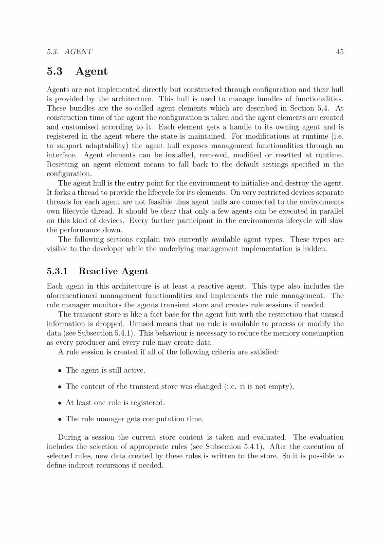
vocation links are shown. . . . . . . . . . . . . . . . . . . . . . . . . . . . . 475.4 Communication Infrastructure - A single environment with two example
agents is shown. The left side illustrates the service management part andthe right side depicts the message capabilities. . . . . . . . . . . . . . . . . 53
The first chapter introduces to the topic of this thesis - the development of a scaleable agentarchitecture. First the profit of such a system is examined. In this context the currentmarket for computing devices of various kinds is considered to identify hardware platformsthat might benefit of the proposed architecture. Thereafter the problem is summarisedand some basic goals are presented. The last section provides the outline of the thesis withshort introductions to the following chapters.
1.1 Motivation
Computers have become an essential part of our life and are available in different typesfor different purposes. These range from stationary workstations and PCs over portablecomputers like mobile phones and PDAs to embedded systems. The main difference be-tween them are the capabilities and their visibility to potential users. To support usersand developers in at least two different cases, an scalable agent architecture is feasible.
1.1.1 Portable Applications
Imagine a personal assistant agent. It manages the time schedule of his owner and gathersnews for him. The user profits most from such an agent, if he is able to take it to hisportable device. On this device the agent drives his computations down and switch toan reactive mode. So on the way the user can access the assistant’s informations whilethe battery power of his device is preserved. Later on, back at the workplace, the agentshould migrate to the desktop machine to switch back to a proactive mode and to continuegathering news.
Without the scalability of the agent this is not possible. Of course the operating system(or virtual machine) on the device should support the migration of applications. Handheldcomputers like PDAs and SmartPhones are appropriate for this scenario.
1
2 CHAPTER 1. INTRODUCTION
1.1.2 Steering and Automation
The agent programming paradigm is well-fitted to implement steering functionalities forautomation purposes. In recent years consumers are supported with technology to au-tomate concerns in their home. For example there are embedded systems with differentsensors available to measure heating, lighting and humidity conditions as well as camerasto record intrusions and so forth. These should be controlled automatically for exampleby autonomous agents.
Some systems are powerful enough to host an operating system and applications directly(for example the SunSPOTs1). Others support only a wired or wireless communication in-terface with which the data can be obtained. Thus a so-called sensor network has to tacklewith different types of connectivity and should support a common communication abstrac-tion for steering agents. So here, the focus for the architecture lies on the communicationinfrastructure and the simplification of agent development.
1.2 Problem Statement
In this thesis the attempt is made to develop an architecture that support the imple-mentation of scaleable agents2. Scalability is an important issue in the development andclassification of hardware systems and also of software systems. For this thesis the scalabil-ity of software systems is relevant. As stated in [Det01] there are several types of scalabilityfor software systems:
• Total Dynamic ScalabilitySoftware systems can be adjusted to the underlying hardware at runtime. Thisrequires the system to be modular and capable of changing modules
• Partial Dynamic ScalabilityAdjustment of software systems requires a restart.
• Static ScalabilitySoftware systems have to be recompiled to be fitted to the target hardware.
So the total dynamic scalability is most appealing yet it cannot be realised for everysystem. One have to keep in mind that the capabilities of a software system depend onthe capabilities of the underlying runtime environment. The software system can runnatively and thus directly upon the operating system or in a virtual machine like theJava Runtime Environment (JRE) or the Common Language Runtime (CLR). It is morechallenging but possible to develop native software that is totally dynamic scaleable. Butnative software will not run on devices with at least another operating system on them.
1http://www.sunspotworld.com/2The term “agent” is somewhat overloaded and spongy. For now you can think of an agent as of a
software entity that can communicate, react on events and do some computation. In Chapter 2 the usagefor the term ”agent” is specified in more detail.
So the use of a virtual machine releases the tie to a specific operating system. But it alsoposes some restrictions on the scalability of software systems. If a software system cannotdetermine the available resources or hardware interfaces it cannot adjust itself suitablyto new hardware configurations. For partial dynamic scalability the same reason can beapplied. So at least the static scalability may be reached for runtime environments that donot support resource probing functionalities. This results in the following sub-problems:
• Identifying a suitable runtime environment to realise the mentioned architecture.
• The architecture must provide at least static scalability where no better type can bereached.
• The architecture must specify the communication infrastructure the agents may relyon.
The answer for the first problem may affect the complexity of the solution of the othertwo. So the complexity is part of the trade-off between availability of the chosen virtualmachine and its support for scaling. The details of these problems and the tasks that arisefrom them are described in their devoted chapters.
1.3 Goals
In this thesis an extensible architecture is realised. The goals for this architecture can besummarised as follows:
• It should connect devices with different capabilities through a common simple com-munication infrastructure. Agents should be able to exchange messages without theknowledge about the underlying communication protocol and hardware interface.Also this infrastructure have to provide administrative messages only send betweenhosting environments.
• Agents should be modularised and the resulting elements should not be directlydependent on each other (for example via static references). This will ensure one kindof scalability as elements can be leaved out if available resources are not sufficient orpresent.
• Agent development should be eased so that hardware independent elements can bereused without any modifications on all supported devices.
1.4 Outline
This thesis is structured as follows:In Chapter 2 terms related to this thesis will be introduced and described. It eases the
4 CHAPTER 1. INTRODUCTION
understanding and concretise the meaning for ambiguous or spongy ones.
The numerous similar or related works will be presented in Chapter 3. It is tried there tosurvey the current state-of-the-art while focussing on the characteristics of the realisations.
After these introducing chapters the design of the system is worked out. To do this Chap-ter 4 analysis the demands on the system and describes the design decisions that leads toan abstract system concept.
This concept will be used in Chapter 5 to create the object model. There the imple-mentation steps are described.
To prove the functionality the architecture is then tested in Chapter 6 with a concretescenario.
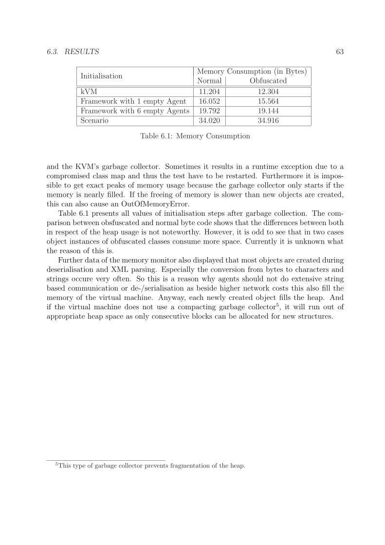
Chapter 7 summarises the approach and provides some ideas for future developments.
Chapter 2
Background
Many terms, especially those used in computer sciences, are elastic words and usuallylead to misunderstandings. To avoid this and to provide a better understanding thischapter introduces definitions of basic terms and concepts. The meanings proposed hereare consequently used in this diploma thesis.
This chapter starts with the definition of the agent term. It provides a survey ofdefinitions in the literature and formulates the meaning in this thesis. Later on the relationbetween distributed artificial intelligence and middlewares will be shown. The last sectionwill identify the capabilities of embedded systems and how they relate to this thesis.
2.1 Agents
As it is already mentioned in the title of this thesis the term ”agent” have to be explainedand its meaning in this work have to be emphasised. First we may take a look on commondefinitions in the literature. It can be seen [FG97] that in different research or developmentprojects the term ”agent” is used and interpreted in different ways but with more or lessintersections. As proposed in [FG97] naming agent properties separately seems to bemore convenient. Many agents and agent systems are defined to be at least reactive andautonomous [WJK00, Lug02, RN03]. This seems to be a realistic foundation as mostprograms are reacting on one or another event and thus showing reactive behaviour. Thedemand for autonomy ensures that agents can process tasks by their own and are able tosupervise their own control structures. Remember that this property does not require theagent to be modifiable. It can also act autonomously with a static set of actions.
2.1.1 Meaning
Agents are a subset of programs with a basic complexity. As it is stated in [FG97] it is notpossible to draw a strict border between agents and non-agents. So the core of agenthoodis used while ignoring fringe groups. The agent description of Russel and Norvig [RN03]makes use of the concept of sensors and actuators. This concept fits well to describe
5
6 CHAPTER 2. BACKGROUND
the interface between the agent and its surrounding environment as it is also borrowedfrom the description of biological organisms. So the notion of an agent will be used asa characterisation of the realised application or program. The ability to react on inputand to generate output and to have some more or less complex internal control flow isexpected of those applications. To what extend these functionalities have to be providedis not strictly defined. For this task a hierarchical order of specialised agents like in [FG97]is used but with some different notations. The root category here is the ”reactive agent”which acts autonomous and reactive but not necessarily active or goal-oriented. This typeof agent is the smallest possible to be realised with the provided architecture. Furtheragents will also have at least all the properties of an ”reactive agent” but combined withother properties like goal-orientation, mobility and so forth (see the listing of usual agentproperties in [FG97]).
2.2 Distributed Artificial Intelligence
Distributed artificial intelligence (DAI) is a subfield in artificial intelligence (AI) research.It can be divided into two subdisciplines [SV00]: distributed problem solving (DPS) andmulti agent systems (MAS). The former deals with issues in information management likeproblem or task decomposition and the synthesis of solutions. Consequently this disciplineacts as the theoretical part of DAI where the foundation for communication, coordinationand cooperation is built up. MAS on the other hand is the more practical part meaning thatthe focus is on the realisation of problem solving entities - agents - and the architecturesbehind them. DAI systems are predestined for areas where single agents are not ableto solve problems by themselves due to resource restrictions, lack of knowledge or lackof capabilities [Jen96]. A further field of application might be the research itself - it ispossible to build up real-world models and with them try to determine and to understandhow biological individuals function [SV00]. The first step to let the agents solve a problemtogether is to enable them to decompose the problem. Then the resulting sub-problemshave to be delegated to appropriate agents or agent groups. After partial solutions arefound they have to be combined to form the solution of the initial problem. As mentionedabove this management problem can be summarise by the following terms:
• CoordinationAgents have to coordinate their doing so that duplications in computing are avoidedor accesses to tight resources are synchronised. Also it makes sense to coordinate theorder of computation and to optimise the flow of information. Thus every agent thatis included in this common solution process should have something to do. In otherwords: it has to be avoided that available resources are unused.
• CooperationThe solution process functions best if all agents pull together. And to ensure this,agents that do not act cooperative have to be identified and their contribution to the
2.3. MIDDLEWARE 7
process should be ignored. It might be also possible to remove these agents out ofthe system.
• CommunicationCommunication enables information interchange. Thus it is also the basis for coor-dinating agents. In heterogeneous multi agent systems a common language shouldbe used so that all participants understand each other.
2.3 Middleware
DAI systems are a special case of middleware. Middlewares are meant to be the layerbetween applications and specific communication infrastructures. These infrastructuresconsists of hardware interfaces and the operating system that provides access to this hard-ware through its drivers. So the main task for a middleware is to provide an abstractcommunication layer which shadows the operating system and hardware. Middlewareframeworks come with different complexities and features. Some middlewares are simpleabstraction layers to increase portability of applications (i.e ACE [Sch94]) and which arefree to be extended as needed. On the other hand there are several other middlewareapproaches which define beside the abstraction layer also management functionalities likejob scheduling and distribution, resource management, and security features (i.e GLOBUS[Fos06]). The common intention of a middleware is, as aforementioned, the abstractionlayer between applications which thus reside on a higher level, and platform (hardware andoperating system) specific libraries on the low level side.
2.4 Embedded Systems
Embedded Systems which are mostly available in consumer electronics are designed to beinconspicuous and do their computations in the background. Whether in mobile phones,washing machines, televisions or cars - embedded systems are spread widely. Their tasksfor which they are developed for are at least as different like the devices they are embeddedinto. So there are systems for driver support in cars which have tight restrictions to handleand process data in realtime. Others are required to comply to standards like bluetoothadapters in mobile phones. To say it in one sentence: embedded systems are used in awide area of application and driver software for those systems are subjected to differentrequirements.
8 CHAPTER 2. BACKGROUND
Chapter 3
Related Work
The first chapter described the tasks for this thesis and proposed goals to reach an ad-equate solution. Basic definitions of concepts were provided in chapter 2. This chapterconcludes the introductory part of this thesis with a detailed look at related work. Thechapter is divided into two sections. The first is dedicated to a native approach which ismainly designed for performance and low memory consumption. The second section dealswith approaches that use a runtime environment and which are consequently interpretedapproaches. They are designed for portability and for realising mobile applications. Anattempt is made to describe all approaches as comprehensive as possible with the focus ontheir comparability.
3.1 Native Approach
As mentioned above, native approaches are mainly desired in applications that demandreal-time computation, low power and memory consumption, and other restrictions to theusage of resources. This section introduces an interesting operating system for embeddedsensors and describes an middleware approach that is built upon this system.
3.1.1 Tiny Microthreading Operating System (TinyOS)
TinyOS [Hil00] is an operating environment especially designed for embedded networkedsensors. It uses C as basic implementation language but offers “a styled version” of it tothe application developer. The compiler for TinyOS translates the required modules ofthe operating system and those of the application into the machine language of the targethardware.
TinyOS is scaleable and supports smaller and more integrated sensor designs as well asthe crossover of software components to hardware. It uses hardware resources as efficientlyas possible while also supporting modularity and realtime event processing whereby poweris the tightest resource. The demands results in the following features TinyOS offers:
9
10 CHAPTER 3. RELATED WORK
• ModularityTinyOS and the applications that are built on top of it are divided into a collectionof components. These components together with a tiny scheduler constitutes thecomplete system that is able to run on sensor hardware. A component consists offour interrelated parts: the set of command handlers, the set of event handlers, thebundle of simple tasks and the encapsulated frame of fixed size. Important to notehere: the frame is needed to allocate the execution stack so the other three partsare running using this frame. TinyOS divides the components into three differentcategories. At the lowest level are those which support an abstraction of hardwaredetails. These components map the physical hardware into the component model ofTinyOS. This is done by connecting handlers to hardware interrupts which can beexternal interrupts, counter, or timer events. So the root of an event chain is alwaysa hardware component that was triggered. Another category are synthetic hardwarecomponents. These are used to simulate the behaviour of advanced hardware. Asstated in [Hil00] synthetic hardware components can be viewed as an enhanced statemachine which could be directly implemented in hardware. The last category ofcomponents are the high level software components. These components are used toperform control, for routing and for data transformations. They are independentfrom the hardware and thus can be used on different platforms.
Components are linked at compile time to reduce runtime overhead. To do so theinteraction between components has to be described in specific files in addition to thestandard C header files. As components communicate through events and commandsthe public interface of each component and thus the accepted events and commands aswell as the triggered events and commands have to be declared. The TinyOS compilerwill then compile the components and link them statically to the aforementionedcomponent graph.
• ConcurrencyTinyOS uses an event-based model to realise concurrency. The advantage of thisapproach in contrast to the threaded model is that there is only one stack neededfor the complete execution while the thread model manages for each thread onestack. Consequently, the memory consumption is reduced. The disadvantage is thatthe performance of concurrent tasks depends on the computing time as each task isatomic with respect to other tasks.
• Control FlowThe root for each control flow is an event that was created due to an hardwareinterrupt. These events can be handled by other components which then again canfire events or trigger commands. Events can be seen as the delegation of informationfrom the hardware to high level components - they build the up-chain. Commandson the other can be seen as the delegation of instructions from high level componentsto the hardware - they build the down chain. Cycles in the event-command chainare prevented due to the restriction that commands cannot trigger events.
3.1. NATIVE APPROACH 11
Figure 3.1: The main architectural components of TinyLIME. Taken from [CGG+05]
3.1.2 TinyLIME
One interesting application that makes use of TinyOS is TinyLIME[CGG+05]. It is a data-sharing middleware that is based on LIME[PMR99], an extension of the tuple space modelLinda to support mobility and thus mobile ad-hoc networks. Figure 3.1 displays thecomponents of the TinyLIME architecture. The communication model of TinyLIME (andalso of LIME) consists of a transiently shared tuple space. The base station is hereby inconnection with some sensors (“motes”) and hosts the tuple space that contains the dataof these motes. Sensor tuples are predefined four-tuples containing the sensor type, actualsensor reading, epoch number and the timestamp of the last reading. The base stationitself and the API for client agents that want to access sensor data are written in Javaas LIME is also an Java implementation. The software that runs on the motes is mainlyfor delegating sensor data to the base station in communication range and is written innesC, the C derivative that comes with TinyOS. The communication model of TinyLIMEcan be summarised as follows: Client agents are associated with an own interface tuplespace (ITS). Through this they can write data and can read their own data and also datafrom other connected tuple spaces. LIME is responsible for the exchange of the tuples.Tuples are requested through describing patterns. For example, if an agent wants dat froma temperature sensor, it provides the type of the sensor in its template tuple and leavesthe other fields free. So it is possible that more than one tuple matches this pattern.LIME makes no commitment to what tuple is returned but chooses one randomly. Thevisibility of tuples depends on the connectivity of client agents, base stations and motes.Disconnection of a base station or a mote results in a loss of tuples the agent had access
12 CHAPTER 3. RELATED WORK
to before. This is the reason why the shared tuple space is also declared to be transient:modifications may not only occur due to issued insertions or removals of tuples but alsodue to disconnection of tuple providers. To summarise this: LIME and the specialisedTinyLIME are middlewares that manage the connection of tuple spaces and the tupleexchange when tuples are requested. The migration of agents is supported and every datafrom the agent’s own tuple space will be present again after the migration is finished.Agent developers have to keep in mind, that, as the available content of the agents tuplespace highly depends on its connectivity to other tuple space owners, no conclusion can bedrawn if data is not available.
3.2 Interpreted Approaches
Most recent work in the field of agent architectures on small devices were realised withthe use of runtime environments and thus are interpreted approaches. A survey throughthe literature shows that most approaches make use of the Java 2 Platform Micro Edition.This section starts with a description of J2ME and of an alternative Java-based runtimeenvironment. After these environment descriptions some concrete middleware and agentarchitecture approaches will examined.
3.2.1 Java 2 Platform Micro Edition (J2ME)
J2ME and its “kilo virtual machine” (KVM) is a subset of the standard edition of Java. It isdivided into two parts: configurations and profiles. A configuration specifies the foundationof the API. This can be seen as the least common denominator through different deviceswhich offer the same configuration. Currently there are two different configurations avail-able, one for low end devices (like cell phones, embedded systems, etc) called ConnectedLimited Device Configuration (CLDC [Sun03]). And another for middle level devices likePDAs, smartphones etc called Connected Device Configuration (CDC [Sun05]). The latterone offers nearly the same functionalities like the standard edition but with restrictions todeprecated methods and windowing toolkits. Profiles exploit features of the underlying de-vices or just extend the functionalities of the configuration. For CLDC there is the MobileInformation Device Profile (MIDP [Sun02]) which is available on a wide range of consumerelectronic devices. The CDC can be extended with at least three different profiles whichare ordered in a hierarchy. The most restricted called Foundation Profile is also part ofthe Personal Basis Profile which in turn is fully contained within the Personal Profile.The main difference between these three profiles lies in the availability of a graphical userinterface. The following list tries to give an overview of the capabilities of J2ME:
• ModularityBeside the MID-Profile J2ME does not propose or require fixed module or componenttypes. MIDP developers have to implement the special MIDlet class to let theirapplication run on an MIDP enabled device. For the other profiles the standard
3.2. INTERPRETED APPROACHES 13
behaviour from J2SE can be expected. So developers are free to define and implementtheir own module hierarchy and component architectures.
• ConcurrencyLike in the standard edition of Java, J2ME also supports threads to realise con-currency. As threads impose some runtime overhead developers are obliged to notmake unduly use of them. Otherwise the performance of the whole runtime envi-ronment could decrease. So one has to decide how complex applications might beto be runnable on small devices. To synchronise the access to fields or methods thestandard monitor concept of Java is available. Developers which are familiar withJ2SE should not have any troubles while developing for J2ME.
• Control Flow and Lifecycle ManagementOnly MIDP uses a predefined lifecycle management system. MIDP devices do onlyhave one virtual machine running to reduce the overhead of running more than one.So every application that is available on such device will be managed by this virtualmachine. If in some time the memory is not sufficient enough to run all of thecurrently started applications in parallel, the application management system pausesor destroys applications on its own behalf. The MIDlet class provides hook methodsso that applications can react on those state changes and may persist their statesor other important data. State changes initiated by the application managementsystem usually cannot be denied. In some circumstances the system allows the delayof for example a shutdown. All other profiles let the developer implement their ownlife cycle management. There the standard entrypoint for an application is the mainmethod in some class.
• Communication and ConnectionsJ2ME defines a single connector class that can be used to acquire communication con-nections such as sockets. To do so, one has to specify an URI following a predefinedscheme[Ort03]. Which transport protocols are available depends on the capabilitiesof the device. For example only on devices with a bluetooth interface a bluetoothconnection can be acquired. The contract for the connector class is that it throws anexception if a requested connection is unsupported.
3.2.2 JControl
JControl[BT01] is a Java implementation which is targeted at the field of home automationand thus it can be used for control and steering applications. JControl comes with a verysmall subset of the Java 2 Platform Standard Edition and with device specific extensions.The developers of JControl also implemented a virtual machine which consumes at most20 kilo bytes of memory. To reach this all data types with a word length of more than 16bits were stripped out. This results in a near bisection of RAM consumption. Also lessbyte codes have to be realised which reduces the size of the virtual machine. Lets take alook of the features of JControl and its virtual machine:
14 CHAPTER 3. RELATED WORK
• ModularityThe developers of JControl kept an eye on the resource demand of their virtual ma-chine and its library. So as a result, they make extensive use of a so-called broadhierarchy. This is done by defining interfaces for example for the different connectionand communication types. The use of a flat and broad hierarchy that is realisedthrough interfaces let classes grow in size, as every declared method of an interfacehave to be implemented, but reduces the amount of classes that have to be loadedfrom the virtual machine. Interfaces can be ignored by the virtual machine as theydo not provide any logic. JControl also proposes guidelines[BT02] to optimise theresource demand of applications. One guideline requires the application developer touse only as few classes in a block as needed. Also the popular but resource wastingconcatenation of strings with the “+” should be avoided. To help the garbage col-lector examining what classes are unused one can structure the programs by definingadditional blocks. Finally the developer is as free to define classes and modules likein J2ME but he has to keep in mind that deep class hierarchies and the use of manyclasses in a block have a higher demand on RAM and may thus let the applicationbe unusable on very restricted devices.
• ConcurrencyJControl uses a similar concurrency model like J2ME. As there is no operating systemunderneath JControl the virtual machine schedules the threads on its own. Besidethe priorities for threads the concurrency model also supports the use of timeouts forthem. They can be specified at runtime and if a timeout is reached before a threadfinishes its task, the application gets informed through an exception. This providesprimitive realtime processing capabilities. Some optimisations [BT01] were made dueto the nature of the JControlVM to reduce the thread overhead.
• Control FlowThe runtime environment supports only one application packaged in a JAR or in theproprietary archive format provided with the development environment of JControl.Garbage collection is much more intrusive in JControl as the characteristics of thetarget devices (8-bit microcontrollers with at least 2 kilo bytes of RAM) requiresthoughtful scheduling of their narrow resources. So classes are unloaded if they arenot in use and objects that are not referenced anymore are removed as soon aspossible. As mentioned earlier application developers should keep an eye on theirimplementations. Optimisation criteria are given in [BT02].
• Communication and ConnectionsJControl provides access to several bus systems that can be found on the aimedboards. The architects of JControl chose the way to define every communicationlink as a stream. Thus it is unnecessary for application developers to know whattransport is used as everything is accessible through a common interface.
3.2. INTERPRETED APPROACHES 15
Figure 3.2: An example JADE platform. Taken from [BB01]
The project that developed LEAP [ABPR01] was funded by the European Commission for2.5 years and involved several research centres spread across Europe. LEAP is mainly areplacement [Cai03] of the Java Agent Development Environment (JADE [JAD]) kernel tosupport mobile and resource constrained devices but also standard desktop systems. Thefield of application reaches from knowledge management and decentralised work coordina-tion to travel management [BB01]. JADE was developed for desktop systems and thus itis not useable on devices that only support J2ME. However LEAP can be deployed in dif-ferent configurations. Functionalities are modularised and thus described by an interface.Each interface can be implemented in two different ways. If a container cannot supporta functionality then there is only a dummy implementation for it available. In the othercase a real implementation is supported by the container. For example the agent mobilityhad to be declared as an optional functionality as the KVM does not support customisedclassloaders. In case of LEAP running on a J2ME device there is only the dummy im-plementation available. It ensures that applications and agents which are implementedagainst the LEAP API will not break if the deployment location of them changes. Agentscan determine at runtime if a specific functionality is supported by the container they arerunning in or not.
• ModularityJADE and also LEAP consists of several modules that are arranged in so-called con-tainers. Figure 3.2 displays an example platform. Two different container types arespecified. The agent container, as the name implies, acts as a host for agents. It cancontain one or more agents or even none at all. An agent container also includes a so-called Agent Communication Channel (ACC) for message and information exchangewith other FIPA compliant platforms and a message dispatcher for inter-container
16 CHAPTER 3. RELATED WORK
message exchange. The other type is the main container. It is also an agent con-tainer but with more functionalities. As the FIPA[FIP] standard proposes, the maincontainer includes a Directory Facilitator (DF) agent, that provides yellow and whitepages services, and an Agent Management Service (AMS) that controls the lifecycleof all agents hosted on the platform. The main container is usually hosted on adesktop system and per platform there is only one main container available. Furthercontainer modules like a graphical user interface for administration are optional. It ispossible to extend the platform to satisfy application-specific needs. If a new trans-port protocol is needed it can be integrated by providing an implementation of therelevant interface.
• Control Flow and Lifecycle ManagementAs defined in the FIPA specifications, there is an AMS which is the authority on aplatform and manages the lifecycle of all agents on it and all containers which partic-ipate with it. It is hosted on the main container (and sometimes also on peripheralcontainers) and can issue the following management commands[BB01]:
– force a lifecycle transition in an agent
– shutdown a container
– shutdown the whole platform
– activate a management procedure like logging
Agents can also request lifecycle changes and the AMS can decide whether to committhis change or reject it. FIPA defines the lifecycle model with a fixed set of states andpossible transitions between them. A scheduler decides at each round in the agentsmain loop (only when in ACTIVE state) which behaviour to execute. Behaviourscan be added or removed at construction time of the agent and also at runtime fromwithin other behaviours.
• CommunicationThe communication is splitted into two parts. The inter platform communicationwhere a container and a remote platform are involved is done through FIPA mes-sages. These messages have a well defined structure consisting of an envelope and theconcrete payload. This kind of communication is done through the ACC that is avail-able in all containers and which supports one or more Message Transport Protocol(MTP). The other part is the intra platform communication where two containersof the same platform are involved. The communication is done through so-calledInternal Transport Protocols (ITP). LEAP comes with three different ITPs:
1. Internet Inter ORB Protocol (IIOP)
2. Java Remote Method Invocation (RMI)
3. A proprietary protocol over TCP/IP [CLR02]
3.2. INTERPRETED APPROACHES 17
The default protocol is the RMI based one which is used for information retrieval oncontainers. The communication with agents on remote containers is also part of theintra-platform communication. For this type of information exchange ACL messagesare used. For feasibility reasons[BP01, CLR02] only the last protocol is used on smalldevices.
Because of different network settings (i.e. firewalls) the use of one or more protocolsmight not be possible. The developers of LEAP implemented a flexible mechanismto integrate different internal transport protocols: those which are mentioned aboveor protocols from third parties. At least one ITP that is available on some containershould be able to send and handle ACL messages. This behaviour is requestedby the FIPA specification for inter-agent communication. Agents do not directlycommunicate with each other but through their containers. As mentioned abovethe container provides an appropriate message transport system to resolve logicalagent addresses to the physical ones and to deliver the messages conforming to theFIPA-ACL specification.
IIOP is available because “the first FIPA specifications did not allow many commu-nication protocols, but they prescripted that all FIPA agents were addressed througha CORBA interface”[BP01]. So first implementations of FIPA platforms relied onIIOP, however this protocol is also adopted in newer implementations. The use ofRMI for intra-platform communication is preferred by JADE as it means an ease ofimplementation and also a better performance.
3.2.4 Extendable Mobile Agent Architecture (EMAA)
EMAA[LRTK98] is an architecture that focusses on the mobility of agents and distributedproblem solving. Problems should be divided into subproblems which in turn form compo-nents that can be distributed through some network. The architecture therefore adheresfrom the standard message passing paradigm.
• ModularityEMAA comes with three major components: agents, servers, and the dock. Agentsare user-defined and implement the functionalities for their specialised work. Unlikeother agent definitions the developers of EMAA define their agents to be able tocarry and execute a number of programs. They introduced the concept of taskableagents where tasks are programs which achieve goals. So the goal of an agent is tocomplete all task. The mobility of agents requires the consideration of the task itselfand also the location of the tasks performance.
An agent has an itinerary by default and there can be inter-task relationships de-fined. There are several advantages of splitting goals to subgoals and packaging theprograms which accomplish a task into their own components. First it increases theparallelism. Agents can run tasks in parallel or delegate tasks to other agents oreven run the tasks on different nodes. Another advantage is the configurability of
18 CHAPTER 3. RELATED WORK
agents. Tasks can be removed or added as long as no existing constraint is violated.Finally the components are reusable in the case where two problems can be dividedand common sub-goals can be identified.
Servers are specific implementations that exploit resources on their host node. Ingeneral the implementations are device or node specific and thus not portable. Theyshould be used to unify access to for example databases and offer an abstract interfacefor agents.
The dock is the common access point on every node in the network. It is a daemonprocess that is able to receive, transmit, or initialise agents and which acts as aregistry for available servers on the node. Furthermore it contains an event managerfor listener registration and event delegation.
• ConcurrencyEMAA realises a middleware that is able to migrate agents between the nodes in anetwork. The components in the agent can be executed in parallel if they are notdepending on each other. They may be executed on the same node or on differentnodes if more feasible. Thus the computational effort can be distributed throughoutthe network.
• Control Flow and Lifecycle ManagementThe initial entry point for an agents life is the agent manager of the dock. It registersand initialises the agent. During initialisation a handle to the dock is handed overso that the agent is able to obtain handles of servers from the node. The itinerary ofthe agents is used to schedule the execution of the components (tasks). Componentsare able to issue the transmission of agents. The state of the agents components willbe preserved and the transmission is done through the “communication facade” ofthe dock.
• CommunicationThere are several different kinds of communication. First there is the possibility tosend an agent from one node to another. The dock with its communication facade isresponsible for maintaining connections to other nodes in the network. Furthermorethe agent migration is done through this component. Some optimisations can bemade if more then one agent is scheduled for transmission to the same destinationnode: if these agents only differ in the tasks they are carrying, their itineraries canbe combined and a single agent is transmitted. Also components that are availableon the destination hosts should not be transmitted to reduce communication costs.
Another communication channel are the events. During execution of a componenterrors may occur or components, or servers may trigger notification events. Thedeveloper can register handles to different events which are invoked by the eventmanager if the specific event is fired. Custom setup of connections from within theagent is possible but not advisable. Communication should only happen throughevents or the communication facade to ensure platform independence.
3.2. INTERPRETED APPROACHES 19
Figure 3.3: The Structure of a Complet Reference. Taken from [HBSG99]
There is a project [CPA+04] that makes use of EMAA. It is targeted at the field ofMobile Ad-hoc Networks (MANET) for example in catastrophe scenarios where severalrescue workers should be connected together. The multi-agent system for such scenarioshave to be self-stabilising. This means that routes for message transfer have to be changeddynamically to avoid packet losses or to minimise the transmission times. Furthermoreagents have to be migrated if for example the battery power of a device is decreased intoa critical level. Security issues have to be taken into account for example to prevent illegalaccess. The project summarised in [CPA+04] is in the beginning phase.
3.2.5 FarGo-DA
FarGo-DA[WBS02] is an extension of the FarGo[HBSG99] system targeted at “networkedlightweight portable computers”. FarGo introduces a model for distributed applicationsto support their dynamic layouting through the network. FarGo-DA extends this modelby means of disconnection awareness of applications. The programming language usedis Java. Both architectures are targeted at systems which provide code mobility, RMI,and reflection and thus can also be used on CDC devices with the RMI optional packageinstalled. In the following the capabilities of FarGo and its extension is depicted.
• ModularityThe main module of FarGo is the core. Each core runs in an own instance of the JavaVirtual Machine. They act as hosts for Complets and provide movement and invoca-tion implementations and reference handlers. Furthermore it comes with a Completrepository with a lookup service given a logical name. Complets are the containersof the application logic and functionalities and build the first facet of FarGo applica-tions. Thus Complets are collections of objects specified to perform given tasks. Theycan be accessed through a specific interface, the anchor. It prevents direct referencingof the concrete Complet objects to leave space for different reference semantics. These
20 CHAPTER 3. RELATED WORK
semantics build the second facet. Some basic semantics are provided by the FarGoarchitecture but they can be extended by the application developer. For example thebasic link acts as a remote reference between two former collocated Complets runningon different hosts yet. Further types are pull to relocate referencing and referencedComplets together, duplicate, and stamp for the replacement of a relocated Completby another collocated Complet of equivalent type. FarGo-DA extends these referencetypes by disconnection awareness. This means that further references are introducedwhich react on pre-disconnect and post-connect events. They are further explainedin the communication description. The third and last facet are the relocation policieswhich are implicitly available in the disconnection awareness extension of FarGo-DA.They specify the relocation behaviour for the Complets i.e. what triggers a relocationand to what destination should it be processed. The structure of a Complet referenceis depicted in Figure 3.3.
• ConcurrencyAs mentioned above Complets are the relocatable units of an application. They canbe distributed through the network and run on different cores. Complet developersare free to use threads to realise in-Complet concurrency and also for concurrencybetween different Complets in the same core.
• Control Flow and Lifecycle ManagementThe core with its components is responsible for managing Complets startup, stop-ping and migration. Furthermore its reference handler is responsible for resolve andtracking references to Complets.
• CommunicationCommunication between Complets is done through method invocation. Dependingon the used reference type this can trigger a call cascade (see Figure 3.3) or it isjust an invocation of a locally available method. In FarGo-DA several referencetypes realise implicit relocation strategies. The clone reference means that beforedisconnection the original referenced Complets which are not available locally on thecurrent device are cloned and transferred to it. There are also asynchronous referencesemantics available like StoreAndForward or Depart. The former stores operationsmade while disconnected and delegates it to the target Complet when reconnected.The latter one delegates requests prior disconnection and retrieve the results uponreconnection. Further reconnection reference semantics are used if Complets wherecloned or replaced prior disconnection. So there is the possibility to ignore changes inthe local Complet and to purge it. Also one can let the system overwrite the originalComplet with the local one. The last semantics uses timestamps to decide whichstate of the Complet should be preserved. At last there is also a merge possiblebut this requires the developer to help the system. Several “disconnected aware”datatypes are available that should be used if automated merge is required.
3.2. INTERPRETED APPROACHES 21
Figure 3.4: Architecture for ToothAgent. Taken from [BGF05]
3.2.6 Specialised Systems
Beside the aforementioned more generic approaches there are several other available thatare developed for specific scenarios. For example [BGF05] proposes an agent system calledToothAgent that supports people to form social networks. Its communication is based onBluetooth because this network has enough range for the platforms scope. Social networksare described to be mostly dependent on geographical collocation of people as this nearnessexpresses also common interests. ToothAgent is mainly targeted at handheld devices suchas cell phones and PDAs. Its architectural design is depicted in Figure 3.4. Mobile deviceshost the user interface and have to establish a connection to a nearby server. Then theuser have to register himself, if not done before, and a personal agent will be hosted onthe remote server. Thus this is a thin client approach as users delegate their tasks or usesservices through their external avatar agents. The backend of ToothAgent is implementedwith JADE (see Subsection 3.2.3).
Another approach which supports museum visitors with information about exhibits isKORE [BCS03]. It requires that users are equipped with a handheld device which haveat least an infrared communication interface. Each exhibit is arranged with an infraredbeamer to detect users standing before it. The specific agent that controls the beamerqueries information from the data base server to delegate it to the users device. If thedevice is capable of a wireless connection (i.e. GSM. Bluetooth, Wi-Fi) the informationwill be provided on demand. In this case, the system associate a specific agent to the userwhich maintains the users profile. According to this profile it filters information aboutthe artworks and delegate it to the users device. The architecture of KORE is depicted inFigure 3.5.
Finally there is another interesting approach called PDAgent [CTC04]. Like the namesuggests it is targeted at devices of the PDA class. These devices host the PDAgentplatform which provides access to the agent servers and an associated gateway server.
22 CHAPTER 3. RELATED WORK
Figure 3.5: Architecture for KORE. Taken from [BCS03]
Users can now download the binaries of mobile agents and store them into the device-local database. On the device they can configure their agents and submit them to thegateway for execution. Thus the complete processing of the agent resides on appropriateservers. Appropriate means that the server provides the specific capabilities the agentrequires for its computations. So a filter agent which is delivered to filter content from aspecific database will be transmitted to the specific server which hosts this database. Sothis approach tries to reduce network costs and to support offline computations.
Chapter 4
Analysis and Design
Section 1.3 proposed several goals to give an idea for the architecture of interest. Thischapter will now refine this informal idea. It starts with a statement to the implementationlanguage. Then the architecture requirements are identified leading to a specific systemdesign. All design decisions will be discussed in detail and the requested behaviour of thesystem will be illustrated with several use cases.
4.1 Implementation Language
Strong distinctions in target hardware platforms demand an early statement to the pro-gramming language. This architecture needs to be portable over those platforms wherebyonly a virtual machine comes into question. Virtual machines, as explained in Chapter 3,are a first abstraction of the “concrete machine” and reduce port issues of applications.This advantage outweighs the disadvantage that virtual machines consume resources bythemselves and thus implying a certain overhead.
The Java platform is most appealing as it is available for many different device cat-egories. Currently most cell phones on the market are Java enabled. Also many Smart-Phones, PDAs and other computers of the handheld class support Java or allow users toinstall it. So the decision is made to implement this architecture in Java and to ensureportability through different kinds of Java Platform Editions (Subsection 3.2.1). The eval-uation of differences between Java editions resulted in further problems that have to beconsired.
4.2 System Features and Functionalities
Scalability is the core capability of the architecture and so most of the features describedin the following subsections are strictly related to it. Here, one essential part of scalabilityis the portability of agents. This demands a specific foundation for developers that ensuresplatform independence and thus independence of the concrete and virtual machine. It isimportant to note here that the foundation itself needs not to be portable because it is
23
24 CHAPTER 4. ANALYSIS AND DESIGN
part of the framework and thus it has to be realised to exploit as much capabilities of thetarget platform as possible. Only with this tailoring of the framework the scalability canbe reached. Agents that are strictly developed using this foundation will be executable onall devices for which the concrete foundation implementation exists. Also agents may usefurther capabilities that are not present on every supported platform. Their portability isreduced but to keep this issue manageable the system have to propose a module conceptfor agents.
4.2.1 Modularity
Developers should experience support in the implementation of agents. These agents haveto be useable on different devices and virtual machines with least modification effort.The aforementioned foundation is, in other words, the least common denominator of allsupported platforms. Thus it is often not sufficient to implement all functionalities ofagents. To support agent developers in exploiting device dependent capabilities it is betterto introduce a module concept for agents. This has the following advantages:
1. Elements can be tested separately or replaced by mocks1. This secures the develop-ment process.
2. Interfaces are the access points for elements and thus hide the details of the concreteimplementations. So it is possible to realise several elements that provide the samefunctionalities but use different capabilities of the underlying system. In other words:elements are exchangeable and so agents could be reconfigured to fit the platform’scapabilities.
A possible module concept should be based on the different functional parts of theagent. Remember the proposed definition of agents (Subsection 2.1.1). It is a good decisionto define elements for sensors and actuators. The developer is then free to use whateverdevice capability he wants as long as these details remain covered by these proposed elementinterfaces.
4.2.2 Concurrency
The module concept should also cover concurrency issues of agents. Each element interfaceshould pose restrictions on concrete implementations. Scalability demands careful usageof tiny resources and thus the system should be able to run agent elements in just onethread of control. This worst case for the concurrency model is similar to a pipeline whereelements are processed successively and is thus coarse grained. Here, the main constrictionfor concrete implementations is their computation time.
In the best case, where the platform has enough resources so that every element canbe processed in its own thread of control, the concurrency model of the virtual machine isused and is thus finer grained.
1Modules that realises defined interfaces but are only dummy implementations for test purposes.
4.2. SYSTEM FEATURES AND FUNCTIONALITIES 25
Constructed DestructedRunning
Figure 4.1: Minimal Lifecycle of an Agent
The least common denominator approach should handle both with its module concept.So it will define a concurrency model that is located somewhere in-between the two ex-tremes. It is clear that this will become the main source of demands that devices shouldmet. Otherwise they cannot be supported by the framework.
4.2.3 Control Flow and Lifecycle Management
The concurrency module already brings in the decoupling of agent elements from theirthreads of control. This control have to be exercised by the framework itself as it isspecifically implemented to mirror the capabilities of the underlying platform and thus itis able to use the appropriate concurrency model. Agents will remain portable while theirperformance is adapted automatically.
A lifecycle management should support at least three different phases — construction,destruction and a running phase. During the construction phase a new agent is created andits elements are initialised. In this phase elements can also acquire resources if needed. Inthe destruction phase the agent and its elements are destroyed and acquired resources arereleased. The running phase renders the agent as active and all of its elements are managedby the system. This simple lifecycle model looks like depicted in Figure 4.1. It have tobe emphasised that the running phase might also be a composed phase defining severalsub-phases. This is necessary to model agent migration for example. The proposed simplelifecycle is thus only the minimal one which the lifecycle management have to support.
4.2.4 Communication
The communication capabilities of the devices are heterogeneous. From low range radioor infrared interfaces to wireless or wired LAN2 is everything available. Thus, a commu-nication system should be able to handle this heterogeneity. Agents should be able tocommunicate with each other even beyond their host’s capabilities. It is clear that directconnections without so-called hops in between cannot be supported. But means for trans-lating through different interfaces and for routing the data are required. Furthermore itmight be necessary to support authentic communication. This is a harder task because
2Local Area Network
26 CHAPTER 4. ANALYSIS AND DESIGN
due to the aforementioned lack of direct connections, a stable connection emulation has tobe realised.
Further analysis should tackle with the question of communication security in relationto the fields of application and the communication range of participating devices.
4.3 Structuring
The previous section displayed it and it should be obvious that agents are set aside fromthe system. They depend on it, but are not directly part of it. So the first entities ofthe architecture that can be explicitly identified are System and Agent. The concretecomposition of agents is the task of their developers and thus out of the scope of thisthesis. Only the demand for modularity have to be implemented by the architecture here.Thus the entity Agent will not be divided any further but left as it is.
However, the entity System is too abstract. To provide finer grained subentities for it,the aforementioned features and functionalities are analysed to group them and thus toidentify further entities.
Modularity is an abstract property of the architecture (and most important for agents)and is not mapped directly in the system. The next two features in the list, provided in theprevious section, are concurrency and lifecycle management. Beside the fact, that they alsodescribe abstract properties, they can be directly modelled as entities. The explanationof both features reveal at least one great commonality: the management of threads. Thisleads to the decision to realise both functionalities within a single entity. An appropriatename for it would be Lifecycle System because these management issues are closely relatedto the agents lifecycle.
The last point is communication. Its description does not reveal any serious dependen-cies or commonalities to other functionalities. Thus it is at hand to implement it into anown entity. Communication System will be an appropriate name for it.
This first structuring of the architecture is depicted in Figure 4.2. The interactionsbetween the coloured entities are discussed in the following section.
4.4 Use Cases
The following use cases are not exhaustive, yet they are the most essential ones. Theydescribe the interactions between system and agents according to the aforementioned func-tionalities. First, use cases for the Lifecycle System are discussed which are depicted inFigure 4.3. Hereafter the Communication System is attended. Its use cases are depictedin Figure 4.4.
4.4.1 Create Agent
A core functionality of the lifecycle system is the creation of agents. This creation or con-struction basically includes the composition of user defined elements (see Subsection 4.2.1).
4.4. USE CASES 27
Agent
Communication System
Architecture System
Lifecycle System
Figure 4.2: Identified Entities for the Architecture
Requester
CommunicationSystem
Lifecycle System
Agent
Check Permission
Reconfigure Agent
Destroy Agent
Create Agent
Process Event
<<include>>
<<include>>
<<include>>
<<subsystem>>
Figure 4.3: Use Case Diagram: Lifecycle Subsystem
28 CHAPTER 4. ANALYSIS AND DESIGN
Agent
Communication System
Lifecycle System
<<subsystem>>
Send Message
OpenCommunication Link
Check Permission
<<include>>
<<include>>
Figure 4.4: Use Case Diagram: Communication Subsystem
It is required that the requesting user, which can be either an agent or a human, provides adescription of which elements have to be combined and how that should be accomplished:
1. Overview
SummaryThe Lifecycle System creates and initialises an agent due to a request.
Preconditions
1. System is running
2. Sufficient resources are available
Success Post ConditionA new agent is running
Failure Post ConditionThe requester is informed that the agent could not be created due to lack ofpermissions.
ActorsLifecycle System, Agent, Requester
TriggersA requester invokes the registration service of the lifecycle system.
2. Main Success Path
4.4. USE CASES 29
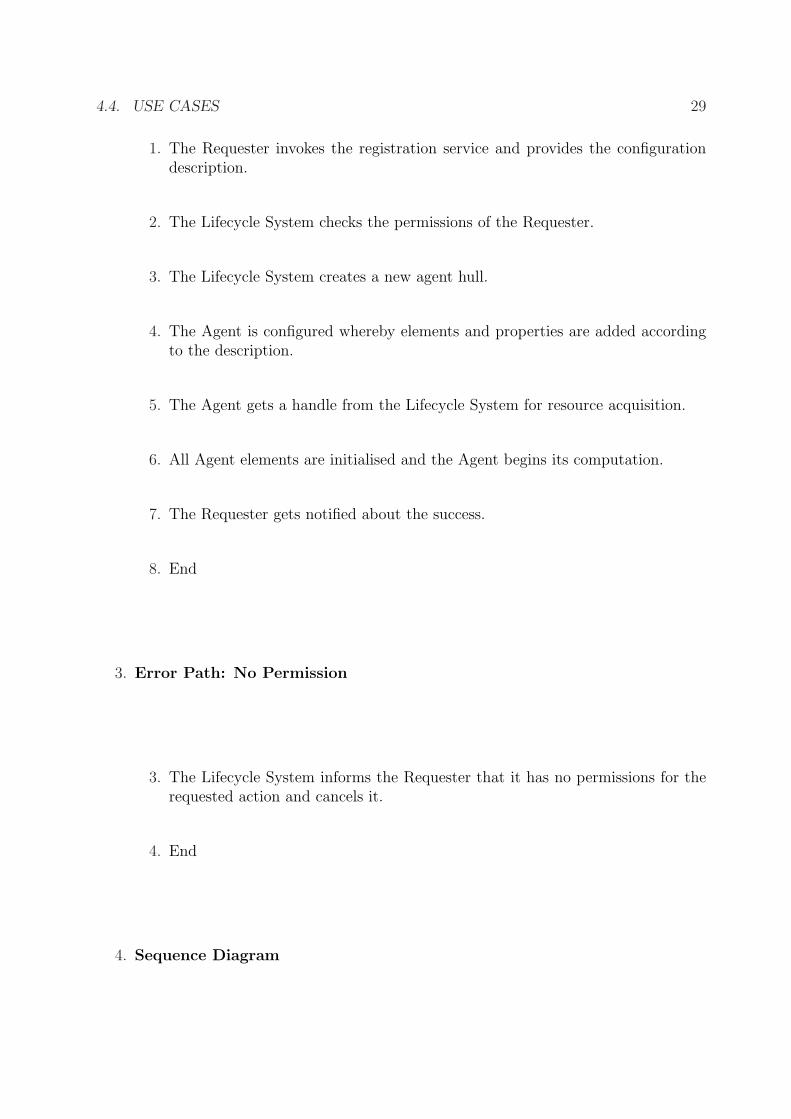
1. The Requester invokes the registration service and provides the configurationdescription.
2. The Lifecycle System checks the permissions of the Requester.
3. The Lifecycle System creates a new agent hull.
4. The Agent is configured whereby elements and properties are added accordingto the description.
5. The Agent gets a handle from the Lifecycle System for resource acquisition.
6. All Agent elements are initialised and the Agent begins its computation.
7. The Requester gets notified about the success.
8. End
3. Error Path: No Permission
3. The Lifecycle System informs the Requester that it has no permissions for therequested action and cancels it.
4. End
4. Sequence Diagram
30 CHAPTER 4. ANALYSIS AND DESIGN
sd Create Agent
:Requester :LifecycleSystem
request("create agent", D)
:Agent
<<create>>
configure(D)
initialise(H)
alt
refCheckPermission
[no permission]
[permission]
accessDenied
successful
4.4.2 Destroy Agent
Beside the construction of agents the lifecycle should also support the destruction of them.This destruction includes the release of resources:
1. Overview
SummaryThe Lifecycle System destroys an agent due to a request.
Preconditions
1. System is running
2. The agent to be destroyed is running.
4.4. USE CASES 31
Success Post Condition
1. Agent is stopped
2. Resources acquired for the agent are released.
Failure Post ConditionThe requester is informed that he has no permissions to destroy the agent.
ActorsLifecycle System, Requester
TriggersA requester invokes the destruction service of the lifecycle system.
2. Main Success Path
1. The Requester invokes the destruction service and provides the identificator ofthe agent.
2. The Lifecycle System checks permissions of the Requester.
3. The Lifecycle System stops the agents running phase.
4. The Lifecycle System frees all acquired resources and destroys the agent.
5. The Requester is informed that the agent is destroyed.
6. End
3. Error Path: No Permission
3. The Requester is informed that it has no permission to destroy the agent.
4. End
4. Sequence Diagram
32 CHAPTER 4. ANALYSIS AND DESIGN
sd Destroy Agent
alt
:Requester :LifecycleSystem
request("destroy agent", I)
:Agent
stopPhase("running")
finalise
<<destroy>>
refCheckPermission
[no permission]
[permission]
accessDenied
successful
4.4.3 Process Event
Events are means to signal changes in the system or environment. Agents are notifiedand may trigger appropriate reactions on those events. This task is supported with bothsubsystems:
1. Overview
SummaryThe Communication System signals an event. It is queued and processed laterwhere the Lifecycle System grants further computation time.
Preconditions
4.4. USE CASES 33
1. System is running
2. At least one agent is running.
Success Post Conditions
1. The event is processed.
2. The internal state of the agent is adjusted.
Failure Post ConditionThe internal state of the agent remains unmodified.
TriggersThe Communication System signals an event for a specific agent.
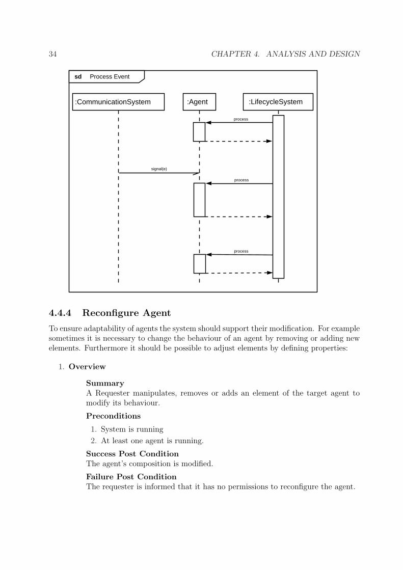
2. Main Success Path
1. The Communication System signals an event due to an incoming message or anagent internal publication.
2. The Agent queues the event.
3. The Lifecycle System provides computing time for the target agent.
4. The Agent selects rules for which the event matches.
5. The Agent process the event and fits its internal state.
6. End
3. Sequence Diagram
34 CHAPTER 4. ANALYSIS AND DESIGN
sd Process Event
:LifecycleSystem:CommunicationSystem
signal(e)
process
:Agent
process
process
4.4.4 Reconfigure Agent
To ensure adaptability of agents the system should support their modification. For examplesometimes it is necessary to change the behaviour of an agent by removing or adding newelements. Furthermore it should be possible to adjust elements by defining properties:
1. Overview
SummaryA Requester manipulates, removes or adds an element of the target agent tomodify its behaviour.
Preconditions
1. System is running
2. At least one agent is running.
Success Post ConditionThe agent’s composition is modified.
Failure Post ConditionThe requester is informed that it has no permissions to reconfigure the agent.
4.4. USE CASES 35
ActorsLifecycle System, Requester
TriggersA Requester invokes the reconfiguration service of the Lifecycle System.
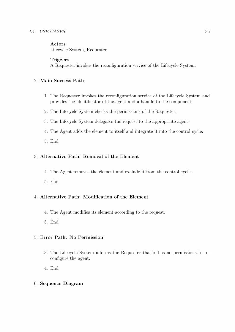
2. Main Success Path
1. The Requester invokes the reconfiguration service of the Lifecycle System andprovides the identificator of the agent and a handle to the component.
2. The Lifecycle System checks the permissions of the Requester.
3. The Lifecycle System delegates the request to the appropriate agent.
4. The Agent adds the element to itself and integrate it into the control cycle.
5. End
3. Alternative Path: Removal of the Element
4. The Agent removes the element and exclude it from the control cycle.
5. End
4. Alternative Path: Modification of the Element
4. The Agent modifies its element according to the request.
5. End
5. Error Path: No Permission
3. The Lifecycle System informs the Requester that is has no permissions to re-configure the agent.
4. End
6. Sequence Diagram
36 CHAPTER 4. ANALYSIS AND DESIGN
sd Reconfigure Agent
alt
:LifecycleSystem:Requester
request("reconfigure agent", I, A)
[no permission]
[permission]
:Agent
processReconfiguration(A)
[A ~ add]addElement
alt
[A ~ remove]removeElement
[A ~ modify]modifyElement
success
accessDenied
success
refCheckPermission
4.4.5 Send Message
As mentioned before this is the mean for agents to communicate with each other. Thecommunication system maintains the channel through which the messages are sent. Aconcrete use case looks as follows:
1. Overview
SummaryAn Agent creates a message and requests its delivery.
Preconditions
1. System is running
2. At least one agent is running
Success Post Conditions
4.4. USE CASES 37
1. The message is delivered
2. The Agent is informed.
Failure Post Conditions
1. The message is not delivered
2. The Agent is notified.
ActorsCommunication System, Agent, Lifecycle System
TriggersAn Agent invokes the message delivery service of the system.
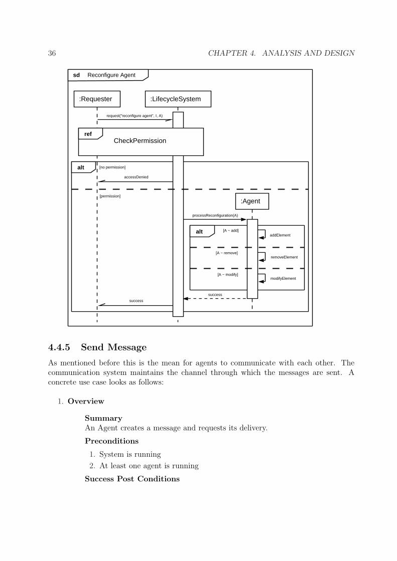
2. Main Success Path
1. The Agent creates a new message containing payload, meta information and thedestination.
2. The Agent invokes the message delivery service of the Communication System
3. The Communication System schedules the message for sending.
4. The Communication System get a new process cycle from the Lifecycle System.
5. The message is sent.
6. The Agent gets informed that the delivery was successful.
7. End
3. Error Path: Communication Error
5. A communication error occurs while sending the message
6. The Agent gets informed that the delivery failed.
7. End
4. Sequence Diagram
38 CHAPTER 4. ANALYSIS AND DESIGN
sd Send Message
alt
:LifecycleSystem
processMessageQueue
[success]
[communicationError]
:CommunicationSystem:Agent
process
deliver(m)
signal("delivery successful")
signal("delivery failed")
send(m)
4.4.6 Open Communication Link
Sometimes it is not sufficient for agents to only send messages through a fixed and prede-fined communication channel. Instead there should also be a way to open links to furtherdestinations for example to a database server or a specific sensor:
1. Overview
SummaryAn Agent requests the Communication System to open a communication link.This link is handed over to the Agent.
Preconditions
1. System is running
2. The Agent is running
3. Enough resources are available.
Success Post Conditions
1. The connection is opened.
2. The Agent owns a handle to this connection.
4.4. USE CASES 39
Failure Post ConditionThe Agent is notified that the link could not be established.
ActorsLifecycle System, Communication System, Agent
TriggersAn Agent requests a communication link from the Communication System.
2. Main Success Path
1. The Agent requests a communication link to a given destination.
2. The Communication System checks the permissions of the Agent.
3. The Communication System checks the availability of the destination.
4. The Communication System establishes the link to the destination.
5. The Communication System returns a handle to the new link.
6. End
3. Error Path 1: No Permission
3. The Agent is informed that it has no permission to create a communication link.
4. End
4. Error Path 2: Destination Unavailable
4. The Agent is informed that the target destination is not available.
5. End
5. Error Path 3: Timeout
5. The attempt of the Communication System to establish a link fails due to atimeout.
6. The Agent is informed that the target destination cannot be reached.
7. End
6. Sequence Diagram
40 CHAPTER 4. ANALYSIS AND DESIGN
sd Open Communication Link
alt
alt
:LifecycleSystem
process
:CommunicationSystem:Agent
open(d)
refCheckPermission
ref
EstablishLink(d)
notAllowed
[noPermission]
[permission]
[unavailable]
destinationUnavailable
[timeout]
destinationUnreachable
[success]
handle
4.5 Concept
The use cases in the previous section provide a fairly detailed overview of the architecture.So now the concept can be described. To do so all necessary system components and theirinterfaces are identified. Two major components are already known: System and Agent.System is not meaningful so it is better to use another term for it later. Both componentsare structured as follows:
• SystemThe complete system consists of a LifecycleSystem and a CommunicationSystem. Itprovides a specific management interface through which agents can be installed, re-moved or manipulated (use cases “Create Agent”, “Destroy Agent” and “Reconfigure
4.5. CONCEPT 41
Listener
:RuleManager
Configurator
LifecycleHandler
<<component>>
:Agent :Environment
:AgentElement
<<component>>
:Rule
<<component>>
:CommunicationSystem
<<subsystem>>
:LifecycleSystem
Communicator
<<component>>
AgentManagment
Figure 4.5: Main Components of the Architecture
42 CHAPTER 4. ANALYSIS AND DESIGN
Agent”). The LifecycleSystem is responsible for maintaining the agent’s lifecycle andfor delegating the processing focus, if the number of threads are restricted. Encap-sulation of the concrete messaging system is task of the CommunicationSystem. Itoffers access for acquiring connections and for sending messages (use cases “OpenCommunication Link” and “Send Message”. Furthermore it is the main source ofevents for the agent.
• AgentAs mentioned in Subsection 4.2.1 agents are built up out of modules. These modulesare called AgentElements. At least one special kind of AgentElement is identified withthe use case “Process Event”: Rules. They encapsulate the reactive behaviour whichis required. A RuleManager supports the filtering of incoming events so that onlymatching rules are executed and thus the usage of computation-time is optimised.The Agent itself provides two distinct interfaces. One for managing the configurationand composition of the agent (use case “Reconfigure Agent”) and another one so thatthe LifecycleSystem can administrate the state and computations of the agent (usecases “Create Agent”, “Destroy Agent” and “Process Event”).
This is a first concept for the architecture. It is depicted in Figure 4.5. The concreterealisation of the identified components are described in the following chapter.
Chapter 5
Approach
This chapter describes the concrete implementation of the design discussed in the previouschapter. It starts with an architecture overview which displays the complete system andthe dependencies between its parts. Hereon each of these parts is described in detail inits dedicated section. This chapter finishes with a description of additional tools and howthey have to be used.
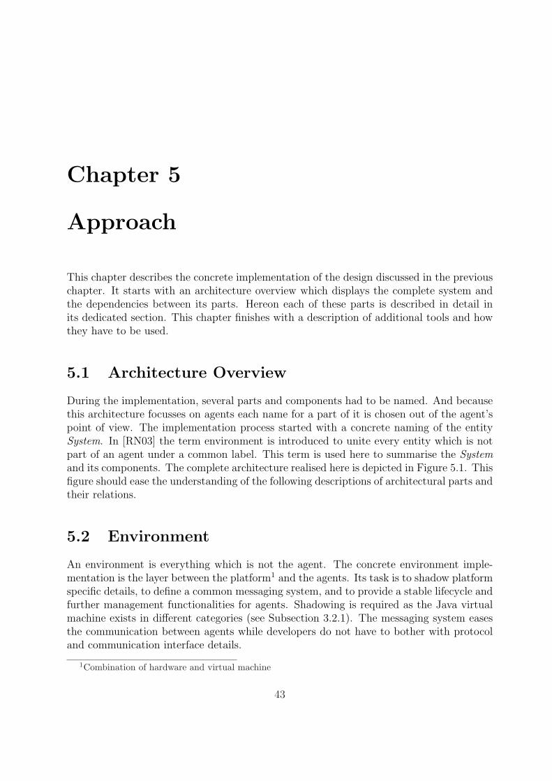
5.1 Architecture Overview
During the implementation, several parts and components had to be named. And becausethis architecture focusses on agents each name for a part of it is chosen out of the agent’spoint of view. The implementation process started with a concrete naming of the entitySystem. In [RN03] the term environment is introduced to unite every entity which is notpart of an agent under a common label. This term is used here to summarise the Systemand its components. The complete architecture realised here is depicted in Figure 5.1. Thisfigure should ease the understanding of the following descriptions of architectural parts andtheir relations.
5.2 Environment
An environment is everything which is not the agent. The concrete environment imple-mentation is the layer between the platform1 and the agents. Its task is to shadow platformspecific details, to define a common messaging system, and to provide a stable lifecycle andfurther management functionalities for agents. Shadowing is required as the Java virtualmachine exists in different categories (see Subsection 3.2.1). The messaging system easesthe communication between agents while developers do not have to bother with protocoland communication interface details.
1Combination of hardware and virtual machine
43
44 CHAPTER 5. APPROACH
Java Virtual MachineKVM / JVM / ...
Hardware + Operating System
CLDC (common base) additional Libraries
Environment
AgentsProducer/Consumer
Figure 5.1: Overview of the Architecture
The implementation of the environment is splitted into two logical elements, which wereidentified within the analysis. The lifecycle system is implemented such that it reducesoverhead of concurrent computations if devices are restricted in computing power andresources. On the other hand it exploits the computational power on increasingly powerfuldevices. This is done with the use of so-called runnable pools. The lifecycle system usesat least one thread which hosts the system pool. Computations are encapsulated usingthe predefined interface java.lang.Runnable or any subinterface and can be added orremoved from this pool. Runnables are executed in cycles which means that after theexecution of the last runnable in the pool, the cycle is restarted with the first one.
On very resource constrained devices the system’s pool is also used to run agent el-ements. This results in a restriction of the maximum amount of concurrently runningagents and also on the duration of encapsulated computations. Blocking ones will alsoblock global computations and thus slow the performance of environment and other agentsdown. On more powerful devices agents are allowed to use own runnable pools and todistribute their elements among them. These specific behaviours of the lifecycle systemand agents are also realised within this architecture. Agent developers are requested toavoid using threads on their own as most concurrency or parallelism issues can be handledby the framework itself.
The lifecycle system is the core component of the architecture and also exercises controlover the communication system, which encapsulates the second element of the environment.The communication system is responsible for message delivery and reception and also forservice request handling. Details to it and its infrastructure is provided in Section 5.5.
5.3. AGENT 45
5.3 Agent
Agents are not implemented directly but constructed through configuration and their hullis provided by the architecture. This hull is used to manage bundles of functionalities.These bundles are the so-called agent elements which are described in Section 5.4. Atconstruction time of the agent the configuration is taken and the agent elements are createdand customised according to it. Each element gets a handle to its owning agent and isregistered in the agent where the state is maintained. For modifications at runtime (i.e.to support adaptability) the agent hull exposes management functionalities through aninterface. Agent elements can be installed, removed, modified or resetted at runtime.Resetting an agent element means to fall back to the default settings specified in theconfiguration.
The agent hull is the entry point for the environment to initialise and destroy the agent.It forks a thread to provide the lifecycle for its elements. On very restricted devices separatethreads for each agent are not feasible thus agent hulls are connected to the environmentsown lifecycle thread. It should be clear that only a few agents can be executed in parallelon this kind of devices. Every further participant in the environments lifecycle will slowthe performance down.
The following sections explain two currently available agent types. These types arevisible to the developer while the underlying management implementation is hidden.
5.3.1 Reactive Agent
Each agent in this architecture is at least a reactive agent. This type also includes theaforementioned management functionalities and implements the rule management. Therule manager monitors the agents transient store and creates rule sessions if needed.
The transient store is like a fact base for the agent but with the restriction that unusedinformation is dropped. Unused means that no rule is available to process or modify thedata (see Subsection 5.4.1). This behaviour is necessary to reduce the memory consumptionas every producer and every rule may create data.
A rule session is created if all of the following criteria are satisfied:
• The agent is still active.
• The content of the transient store was changed (i.e. it is not empty).
• At least one rule is registered.
• The rule manager gets computation time.
During a session the current store content is taken and evaluated. The evaluationincludes the selection of appropriate rules (see Subsection 5.4.1). After the execution ofselected rules, new data created by these rules is written to the store. So it is possible todefine indirect recursions if needed.
46 CHAPTER 5. APPROACH
Consumer Producer Message Sender/Receiver
RuleManager
TransientStoreRule
Reactive Agent
Figure 5.2: Overview of a Reactive Agent
Figure 5.2 depict the flow of information in a reactive agent. Red arrows mark theway of new data. As mentioned earlier data is created by producers and rules but alsofrom the communication system. Green arrows mark the way of actions or outgoing data.Actions are implemented by rules and are delegated to the appropriate consumers or thecommunication system. The Subsections 5.4.2 and 5.4.3 will explain the interface betweenenvironment and agent in detail.
5.3.2 Component Container
This type of agent is an extension of the reactive agent. As the name implies it is ableto host components for time-consuming or non-reactive computations. Furthermore itsupports services to provide access to functionalities. Both element types are described indetail in Subsections 5.4.6 and 5.4.5.
Component containers have a greater resource demand because each component mayuse an own thread. Thus they are currently only supported on appropriate Java Platformsbeginning with the Connected Device Configuration (CDC). Figure 5.3 shows the exten-sions this agent type comes with in relation to the standard reactive agent. The meaningof communication arrows remains the same.
5.3. AGENT 47
TransientStore
Component
ServiceConsumer
RuleManager
Producer Message Sender/Receiver
Rule
Component Container
Figure 5.3: Overview of a Component Container. Only additional communication/invoca-tion links are shown.
48 CHAPTER 5. APPROACH
5.4 Agent Elements
It is stated in the analysis that portability is an essential property for the agents here. Toensure this the analysis proposes a module concept which enables the implementation offunctionalities while keeping scheduling and runtime issues out of the developer’s scope(see also the previous sections). As a result, the architecture developed here defines sixdifferent element types. These types are derived from the functionalities an agent cansupport. All element types imply completely different semantics. Each type can be usedand implemented on its own but it is also possible to combine types to build a module.Thus an element type is not necessarily identical to a module. Usually it is a good idea tocombine the service element with the component that process the service requests. Furtherexamples and the description of all element types are provided in the following subsections.
5.4.1 Rules
In this architecture rules are used to implement reactive behaviour. They consist of aguard and the execution part. Here the guard is used for data selection and to trigger theexecution if appropriate data was found. It consists of:
• Class NameIt specifies the name of the class interesting objects must be instance of. If no classname is specified the super class of all classes, java.lang.Object, is used instead.
• Property Names and ValuesA property is an accessible field of an object. Specified values will be compared tothe appropriate field values of the object. Only properties that are available for theobject should be defined.
Each expression in the guard, the class name and the properties, will be connected witha logical and. Thus an object have to fulfil every given criteria in the guard to trigger theexecution of the rule.
Assuming that all conditions mentioned in Subsection 5.3.1 are fulfilled, a rule sessiondoes the following:
Algorithm RuleSession(R,O)Input: Set of Rules RInput: Objects O from the Transient StoreOutput: New Objects for the Transient Store1. initialise set N2. foreach r in R3. do calculate m = µ (O, r) by taking the guard of r and collect matching objects
out of O4. if #m > 05. then process the execution part of p
5.4. AGENT ELEMENTS 49
6. N ←N ∪ {objects created by p}7. O ←O \ {objects removed by p}8. return N ;
As you can see it is allowed that rules create new objects which are available in the nextrule session. Furthermore a rule may remove objects from the current session so that rules,that are processed later in the session, do not take note of those objects. This behaviourcan be useful but it should be used carefully as the order of rule execution is not defined(due to re-/configuration).
5.4.2 Producers
Producers, like the name reveals, create new data for the agent. They are sensors and thusan interface between environment and agent. This terminology was used because of theagent-centric view in naming and because the term “sensor” does not fit well enough.
There are two different kinds of producers. Active ones, that poll data from the en-vironment and delegate it to the transient store and passive ones that are triggered bythe environment or another source. A producer is declared as active if it implementsjava.lang.Runnable. If such a producer is installed, the owner agent will add it to its (orthe systems, see Subsection 5.2) runnable pool. The producer will then get computationtime in every cycle.
Producers are often an abstraction layer between concrete data sources and the agent.Imagine two different notification producers: one that listens for incoming SMS messagesand another for receiving packages over a bluetooth connection. Both may create notifi-cation objects of the same type for the transient store. Thus other agent elements mayremain totally unaware of the concrete source and only take note of the notification itself.Subsection 5.4.4 describes a specialised producer.
5.4.3 Consumers
Consumers are the counterpart of producers. They are actuators which define the outgoinginterface between agent and environment. As described later in Section 5.5 it should bementioned here, that the Generic Connection Framework [Ort03] is adapted for consumers.This means, that each consumer defines a connection2 through which other agent elementsare able to send data to the environment. This data will be consumed, and translated orforwarded to the specific destination.
Consumers are the layer between portable agent elements and concrete destinations.For example one can implement a shared factbase using two different approaches. Thefirst realisation may only share the knowledge between collocated agents. This is done bysimply defining a singleton3 which distributes references of the data to all agents. Anotherimplemention may use some network transport and enable the forwarding of the data
2derived from javax.microedition.io.Connection3A class which has only one instance. This pattern usually makes a single reference globally accessible.
50 CHAPTER 5. APPROACH
between agents distributed on different devices. These details are hidden for agent elementsthat want to push data into this fact base. Thus both consumers can be used were it isadequate without breaking depending agent elements.
Obtaining a connection to a consumer is the same as opening a network connection.The difference lies in the provided scheme. Each connection is associated to a specificscheme. Thus every consumer defines a protocol name for its connection and every openingrequest whose scheme starts it will be delegated to this consumer. So more precisely theconnections are the concrete actuators while the consumers are the entry points to gainaccess to them.
5.4.4 User Interface Creator
The user interface creator combines the functionalities of a producer and a consumer.A user interface is bi-directional, meaning that it displays information to the user (itconsumes data from the agent) and allows the user to insert data to modify the agentsstate (it produces data for the agent). The difficulty that leads to the introduction of thisspecial agent element is the variety of different UI APIs for Java:
• For the Mobile Information Device Profile there is a specific programming interfacethat mirrors the capabilities of LCD interfaces, which are the standard in devices ofthis class. Only one display object is available for the whole environment so that theuser interface creator needs a reference of it.
• The Personal Profile uses the standard Abstract Windowing Toolkit where everyagent is able to create frames on its own without the need of some global displayobject.
• Devices that only support the Connected Limited Device Configuration might evenhaven none graphical output so that the user interface might be the communicationwith the user through some network connection.
• In the future there might be further APIs for user interface implementation...
Thus these broad differences have to be bridged as good as possible. So the UI creatorhave to implement a further method that receives a handle to a global display if such anobject is available. It should be clear that UI creators are heavily device dependant. Agentsthat have to be deployed on other device classes have to replace at least these creators withthose that support the target platform.
5.4.5 Services
As mentioned earlier, the reactive agent is the most primitive agent that could be imple-mented with this framework. It reacts on changes in its environment and in itself andtriggers small computations which may result in actions. Sometimes it is feasible to offer
5.4. AGENT ELEMENTS 51
an agent the possibility to delegate tasks to another one due to lack of computational poweron the host device or just missing access to resources. Here comes the service interface intoplay which is nothing else but a handle to some kind of remote procedure call.
Imagine the case where a specific database agent is available which maintains a con-nection to the database of its host. This agent may specify services to obtain data from orstore data to it. Every agent that now needs access have to request the appropriate serviceso that a service session can be established. The algorithm for a service session looks asfollows:
Algorithm ServiceSession(I, P )Input: Service Identifier IInput: List of Parameter P for Invocation1. r = createRequest(I)2. forward (r, P ) to an agent that offers service s with identifier I3. if provider agent allows access to s4. then R = process (s, P )5. postResult (r, R)6. else replyAccessDenied (r)7. return;
Service sessions are always asynchronous. This means that the requesting agent — theuser — is not blocked and can process other things. It gets notified as soon as the result iscomputed or an error occurs. This model fits to the systems target to use least resourcesand thus to prevent threads from being locked. The system ensures that each agent thatrequests a service will get a notification of the success or failure, so developers only haveto implement handles to react on these. The functionality of the request communicationand the return of parameters is similar to the “normal” message delivery and is describedin Section 5.5.
5.4.6 Components
Components define an agent element that supports the scalability of the architecture.They are always associated with an own thread of control and are thus extensions to theagents life cycle. The decision to introduce this element type is based on the necessityof time consuming computations in agents. It should be clear that these computationsusually use a greater amount of resources (i.e. processor time, memory, etc) and are thusrestricted to devices with appropriate capabilities. Currently all CLDC devices will notsupport components and will ignore them if they are configured into agents. Section 5.6will explain in detail how the scalability is implemented.
Usually components will be used in combination with other agent element types. So ifthe encapsulated functionality of a component might be interesting for other agents, thedeveloper is free to combine the components implementation with a service implementa-tion. In this case the component gets notified of incoming requests and may process or
52 CHAPTER 5. APPROACH
reject them. Another possibility is to combine the component implementation with a rule.Imagine the case where a search assistant is implemented to support searching of docu-ments. If a human user now issues a search given some keywords by pressing some button(or through another input method) the UI producer will post an appropriate notificationto the transient store of the agent. Assuming that the aforementioned element implementsthe rule functionalities and is registered to this type of notification, it will trigger the com-ponent part of the element and the search can be processed in the components own thread.The result is then send to the appropriate consumer.
Given these two examples one can see, that an agent using components is proactive.Components can generate events and actions by there own and thus the agents does notdepend on input from the environment to do something.
5.5 Communication Infrastructure
It was stated earlier that this architecture provides a message based communication in-frastructure. The core component of it is the message broker. Each message broker is incontact with one or more remote brokers4 and thus forming a so-called broker network.Each client whose broker is connected to it is able to receive messages that are routedwithin it. To do so, the client have to subscribe to specific destinations. There are twodistinct types of destinations:
• TopicsEvery client that is subscribed to a topic will receive all messages that are sent toit. This behaviour is similar to this of a mailing list. This destination type is thestandard type for inter-agent communication.
• QueuesAlso queues might have several subscribers yet each message is delivered to only oneof them. This type is often used in load balancing scenarios where a message mighttrigger resource demanding computations or should be persisted to some database.Here it is used for establishing service sessions.
Beside subscription and unsubscription most message protocols also support furtheroperations. For example transactions can be used to ensure that either all messages froma source are delivered in the order they were sent or none at all. This ensures a certaindegree of reliability.
The concrete infrastructure for this architecture is depicted in Figure 5.4. It supportstwo different communication types:
• Inter-Agent CommunicationInter-agent communication is a topic based communication. Each agent is allowed
4They can also act offline and thus routing messages only within the environment.
5.5. COMMUNICATION INFRASTRUCTURE 53
requestservice://ID
un-/registerservice with ID
send msgto
destination
un-/subscribeto
destination
STOMPMessage Broker
un-/subscribe toqueue/service/ID
un-/subscribe totopic/destination
WLAN,BluetoothInfrared, etc
Communication Interface
Service SessionManager
Agent Agent
send msg totopic/destination
send msg to queue/service/ID(remote service usage)
delegate to broker network(if connected)
signal msg fortopic/destination
signal msgfor
destination
establish remote service session(if connected)
signal msg forqueue/service/ID
invoke service
receive subscriptionsand messages
from broker network(if connected)
Figure 5.4: Communication Infrastructure - A single environment with two example agentsis shown. The left side illustrates the service management part and the right side depictsthe message capabilities.
54 CHAPTER 5. APPROACH
to subscribe to whatever destination it wants and also to issue messages to variousdestinations. The delivery is not coupled to specific authentication mechanisms andthus all messages are publicly visible. In the scope of low-range networks this shouldbe sufficient as with encryption algorithms the content of message can be secured.
• Inter-Environment CommunicationThis kind of communication takes place while establishing service sessions or bycommunicating adminstrative messages. If an agent wants to use a service it opensa specific communication link which issues a service request. This request is a queuemessage and thus it is only delegated to one agent which supports the specific ser-vice. The receiving environment5 defines a new temporary queue target where thecommunication during the service session is handled. It is also possible to use othercommunication schemes as the concrete details are hidden for the service providerand user.
Currently the communication system uses the STOMP protocol. This protocol is simpleand text based and is currently the one which has least overhead - in implementation andalso in computation. This protocol requires a broker to be present in the network orcommunication range of the current device. The communication system connects with itsmessage client to this broker and delegates messages on behalf of the agents. The messageclient itself is accessed through an abstract interface. Thus one can exchange the client ifanother message protocol should be used. For now STOMP is most promising as it alsosupported by the ActiveMQ project. Agents may then communicate with different targetsbehind the ”Active Message Queue” which may use other message protocols like JMS orOpenWire.
5.5.1 Connections
Beside the default message communication, agents are also allowed to open connections toother destinations. But they should not do that directly with thejavax.microedition.io.Connector class but with the environments own open method.This delegation ensures that connections are closed and resources are freed, if the agent whoopened it is destroyed. Furthermore this method shadows differences between consumersand concrete communication capabilities of the device. So it is possible to implement aconsumer which uses the “http” protocol name for simulating an appropriate server andto shadow the http connection of the device.
ACE and also JControl showed, that unified access to communication capabilities isfeasible. They map every connection type to a stream connection. However, the GCF offersvarious different interfaces which foils the portability of agent implementations. Differencesin communication should only depend on protocol names and not on interfaces. Thus inthe architecture proposed here there are also various so-called stream mappers for most of
5Remember that service queues are hosted outside the agents which are thus not informed.
5.6. SCALABILITY 55
the GCFs connection interfaces available. They offer stream based communication evenfor Bluetooth and Datagrams (which are packet oriented).
5.6 Scalability
Agent elements are the foundation for scalability. Every agent is constructed out of them atruntime which avoids static references in the source code. Furthermore the main lifecyclemanagement features are part of the system and thus out of the developers scope. Thisresult in two possibilities to implement scalability.
5.6.1 Optimisation
The first and essential one is to implement and optimise the framework for specific Javaplatforms. Here one is able to meet the restrictions of the platform and the underlyingdevice, for example to reduce the amount of threads or to provide different implementationsof the agents transient stores. It is obvious that devices with very limited resources are notable to host the same amount of agents like a desktop system. But this issue still residesin the system and thus does not concern the agents scalability.
5.6.2 Configuration
As mentioned earlier, the second way to improve scalability is configuration. An exampleconfiguration is depicted in Listing 5.1. The system is free to ignore parts of the configu-ration if resources are not sufficient. So developers should ensure that implementations ofagent elements, which depend on other elements, should do appropriate checks. This avoidsproblems if the system decides to drop specific elements during the construction phase ofthe agent. Currently only components and services are affected when using CLDC (themost restricted Java platform). Here all agent elements which implement one or both in-terfaces will be dropped completely or will just not be registered for these two types. Thedefault behaviour is to drop them completely but the developer can specify in the con-figuration to only ignore the registration as component or service. The following sectiondescribes the preprocessing of configurations that is needed for some platforms.
5.7 Additional Tools
The standard build tool for the framework and for agent implementations is Maven6. Itis based on the component architecture Plexus7 and consists of several components andplugins which support developers for example in project and dependency management. As
<configuration><abstractAgent i d e n t i f i e r=”AbstractAgent ”><elements><element i d e n t i f i e r=” f r ” c l a s s=”com . foo . F i l t e rRu l e ”><properties><meta . r u l e . match>com . foo . SomeObject</meta . r u l e . match><meta . r u l e . prop . answer>42</meta . r u l e . prop . answer>
</properties></element>
</elements></abstractAgent><agent i d e n t i f i e r=”ConcreteAgent”><extend namespace=”org . bar . cus tomisab l e ” i d e n t i f i e r=”SomeAgent” /><elements><element i d e n t i f i e r=” ui ” c l a s s=”com . foo . UICreator ”>< !−− r e g i s t e r only producer par t atm −−><role>de . j i a c . micro . ext . i o . IProducer</ role>
a result of its modular architecture, Maven is extensible through self-defined plugins andcomponents.
It was mentioned before that CLDC is the most restricted Java platform which issupported. Beside other missing features, it does not support the following two:
• ReflectionReflection is a mechanism to let a program analyse its own structure. It providesmeans to query information about classes and instances at runtime and thus enablesprograms to load or configure modules dynamically. Usually in the constructionphase of an agent this mechanism is used to process the instructions in the associatedconfiguration.
• Custom ClassloadersCustom classloaders are used to access arbitrary class locations. They are essentialfor the realisation of agent migration.
This means, that for CLDC no agent migration is available and configuration throughreflection is impossible. Thus it was necessary to implement an own Maven plug-in thatdo some preprocessing and class generation. These two functionalities are described in thefollowing subsections.
5.7.1 Configurations Preprocessing
To circumvent the absence of reflection the Maven plug-in parses all configuration files ofa Maven project (where agent implementations are available) and generate specific Java
5.7. ADDITIONAL TOOLS 57
classes from them. Configuration files are using an XML syntax (see Subsection 5.6.2)and support modular agent descriptions. Thus the plug-in first evaluates whether alldependencies of the specific configuration files are present and then generate Java sourcecode. An advantage is, that for CLDC implementations the developer is informed aboutfailures or inconsistencies in agent configurations at compile time. With the generatedclass the environment is able to create instantiate appropriate agents. It is important tonote hear, that the generated class can only describe agents which configurations were readat compile time. Thus they cannot be exchanged or extended but CLDC does not supportmigration anyway.
5.7.2 Class Generation
Beside the generation of specific configuration classes there is also a need for classes that arehandled within rule guards. Within a configuration file a rule guard specifies one or moreproperties and their values for which the rule should be executed. Usually the concreteevaluation on runtime is handled through reflection. But for CLDC it was necessary tointroduce a specific marker interface. Every class whose properties might be specified inguards should implement this interface. During the compilation process of the project, allits classes are evaluated and for each class that implements the marker specific so-calledproperty accessors are generated. So now the rule managers can retrieve properties ofobjects by using this generated class.
58 CHAPTER 5. APPROACH
Chapter 6
Test and Evaluation
During the implementation of the framework several tests where driven mostly to findbugs and to prove the functionality of specific components. Beside these simple tests therewas also the opportunity to test the complete framework with a concrete scenario. Thisscenario is specified by the “Multi-Agent Programming Contest”1. The contribution forthis contest is implemented by Tuguldur Erdene-Orchir2 using the framework describedin this thesis. It is still under development, yet several results are already available. Butbefore the results are discussed the scenario is described.
6.1 Scenario
The scenario is located in a grid-like world which is depicted in Figure 6.1. Each cell of itis either empty or contains
• an obstacle (tree or bush)
• or the depot (there is only one on the whole map)
• or a gold item
Teams of agents have to explore this world and collect as much gold items as possible.The scenario is turn-based and each agent can issue at most one action per turn. So ateam should coordinate itself to avoid target collisions and thus unnecessary ways whilecollecting gold. Only gold items that are brought to the depot are counted.
It is also possible to hinder the competing agent teams in reaching gold items or thedepot and thus preventing them from getting score. The team with the most gold itemsin the depot wins.
1http://cig.in.tu-clausthal.de/index.php?id=agentcontest072Researcher at the DAI-Labor of Technische Universitat Berlin
59
60 CHAPTER 6. TEST AND EVALUATION
Figure 6.1: The Contest’s World Model
6.2. IMPLEMENTATION 61
6.2 Implementation
Each agent of the aforementioned contribution consist of the following elements:
• ConnectorEvery agent establishs a connection to the competition server where the world stateis hosted and all actions are processed. The connector element maintains this con-nection. It implements the Consumer interface (see Subsection 5.4.3) to hide theconnection details from other elements and to delegate the agent’s actions to theserver. Furthermore it parses the data from the competition server and translatesthem to appropriate perception objects. These objects are broadcasted to all teamagents.
• PerceptorThe perceptor updates the agent’s world model according to the received perceptionsof other team agents and its own. It implements the Consumer interface as the accessto the world model is granted through a connection. Furthermore it implements theProducer interface because after all perceptions are received and the world model isupdated the perceptor fires a notification event. This event triggers the execution ofrules that calculate actions.
• RulesEach agent owns a set of rules. These rules are associated with a specific state ofthe world model and generate appropriate actions. Currently each agent has threedifferent rules for the states:
1. agent stands on the depot cell
2. agent does not carry a gold item
3. agent carries a gold item
Specific actions depend on other agents’ doings and the explored cells. To calculatethe shortest path between two distinct cells, the A* algorithm is used whereby eachunexplored cell is assumed to be a walkable field and each obstacle cell is left out ofthe calculation graph.
• MonitorThe monitor displays the world model of the team for debug purposes. As everyperception is delegated to all other team members each agent has the same view andthus it is sufficient to only let one agent carry the monitor element.
62 CHAPTER 6. TEST AND EVALUATION
6.3 Results
The test implementation and thus the framework and the complete team (six agents) isexecuted using the Sun Wireless Toolkit emulator (version 2.2) and the HTC Universal3
smartphone. The emulator offers a memory monitor and a profiler so it is possible toevaluate the performance and memory consumption of the architecture in relation to theagents. Emulation of concrete devices is not possible because different libraries are availableon them and the bytecodes per cycle speed could only be estimated.
The HTC Universal is used to prove that the test scenario is also executable on portabledevices even though it is not targeted at them due to the extensive communication. It hasthe following capabilities4:
• Intel Bulverde 520 MHz CPU
• Flash ROM: 128 MB, RAM: 64 MB SDRAM
• Client only Mini-USB connector, USB charging, USB 2.0
The connection to the competition server is established with the USB wire.
6.3.1 Performance
The profiler reveals that approximately 35 to 45 percent of the computation time is usedfor communication. This includes the parsing of server responses which are in an XMLformat and the deserialisation of perception objects. As mentioned before, each perceptionof an agent is delegated to each agent in the team. Thus the deserialisation has squareeffort compared to the number of agents. The A* path calculation depends on the numberof obstacles on the map. The more obstacles are present the more cells have to be takeninto account and the longer the path will grow. So the computing time for an agent canincrease to arround a second. The timeout of the server is 3 seconds and all six agents inthe team are using the same thread. In worst case some agents might not send their actionsto the server in time. But as the distribution of agents on the map is random this caseeven had not occured on the aforementioned HTC Universal. And there the performancewas significantly slower as with the emulator on the desktop PC. Finally it could be saidthat most cycles are taken by the agents proving that the framework itself does not wastecomputing time.
6.3.2 Memory Consumption
Using the memory monitor poses several issues. First it slows the performance of the em-ulated application down. This means that the action response timeout of the competitionserver was overriden in all turns. Another problem is the interference between the monitor
InitialisationMemory Consumption (in Bytes)Normal Obfuscated
kVM 11.204 12.304Framework with 1 empty Agent 16.052 15.564Framework with 6 empty Agents 19.792 19.144Scenario 34.020 34.916
Table 6.1: Memory Consumption
and the KVM’s garbage collector. Sometimes it results in a runtime exception due to acompromised class map and thus the test have to be restarted. Furthermore it is impos-sible to get exact peaks of memory usage because the garbage collector only starts if thememory is nearly filled. If the freeing of memory is slower than new objects are created,this can also cause an OutOfMemoryError.
Table 6.1 presents all values of initialisation steps after garbage collection. The com-parison between obsfuscated and normal byte code shows that the differences between bothin respect of the heap usage is not noteworthy. However, it is odd to see that in two casesobject instances of obfuscated classes consume more space. Currently it is unknown whatthe reason of this is.
Further data of the memory monitor also displayed that most objects are created duringdeserialisation and XML parsing. Especially the conversion from bytes to characters andstrings occure very often. So this is a reason why agents should not do extensive stringbased communication or de-/serialisation as beside higher network costs this also fill thememory of the virtual machine. Anyway, each newly created object fills the heap. Andif the virtual machine does not use a compacting garbage collector5, it will run out ofappropriate heap space as only consecutive blocks can be allocated for new structures.
5This type of garbage collector prevents fragmentation of the heap.
64 CHAPTER 6. TEST AND EVALUATION
Chapter 7
Conclusion
7.1 Summary
This thesis presented an agent architecture that supports agent development for variouskinds of devices. Scalability is hereby an essential feature. The kind of scalability whendeploying agents from one device to another mainly depends on the differences of the Javavirtual machines which are running on them. One will not have total dynamic scalabilityif the agents were deployed on a MIDP-enabled SmartPhone and later should run on adesktop system for example. In this case the framework dependencies have to be changedand the project have to be compiled again. But there are no issues if agents are exchangedon devices with the same Java platform.
The cost to ensure at least static scalability of the agents is to implement this frameworkfor each different Java platform separately. Differences in startup handling and availablelibraries make this mandatory.
To provide a better comparability to the projects listed in Chapter 3, the central aspectsof this architecture are presented as follows:
• ModularityAgents are splitted into functional elements. The implementation of these elementsis task of the developer who also have to describe the configuration of his agents withspecific XML files. Given these configurations the environment is able to instantiatenew agent hulls and assemble the elements together.
Reactive behaviours is implemented with rule elements. Sensors and actuators arerealised through producers and consumers. Components and services are supportedon increasingly powerful devices and enable developers to implement proactive be-haviours or to share functionalities.
• ConcurrencyThe granularity of concurrency depends on the virtual machine. In worst case eachactive agent element is processed in one pipeline. Developers are demanded to im-plement all elements with the asynchronous programming pattern and to not use
65
66 CHAPTER 7. CONCLUSION
any blocking mechanism. Furthermore the computations have to be optimised topreserve computation time and memory.
• Control Flow and Lifecycle ManagementLifecycle management is excercised by the environment. It is responsible for thecreation and destruction of agents, for distribution of computation time to all agentsand for event delegation. The environment also offers services to human users to letthem manipulate, remove and install agents.
• CommunicationThis architecture uses a message-based communication approach. The underlyingprotocol — STOMP — is recognised by several message brokers and thus messagescan also be routed or translated to external message-based implementations. Localcommunication is optimised to avoid unnecessary serialisation. Furthermore a con-nection to the network is optional and can be opened or closed whenever the humanuser demands it.
7.2 Future Work
The tests showed that many objects are created during deserialisation and serialisation.This fragments heap space and increase the invocations of the garbage collectors which inturn reduce the system performance. So a task will be to examine better approaches forobject serialisation or to introduce another programming model.
Further improvements can be done in case of agent migration. It was stated earlier,that agents cannot be migrated to CLDC-enabled devices. But there is a way to transmitthe agent sources from these devices to those which support custom classloaders. Hereby,ProGuard’s bytecode obfuscation is not a problem. The obfuscator provides the outputof a mapping file during its execution and ProGuard also offers a retracer to revert theobfuscation. So the task is to calculate information about which agent in a package needswhich classes. This should be done at compile/packaging time of the project. Given theseinformation agents can be transported from CLDC devices to another destination.
Bibliography
[ABPR01] Giovanni Adorni, Federico Bergenti, Agostino Poggi, and Giovanni Rimassa.Enabling FIPA agents on small devices. In Matthias Klush and Franco Zam-bonelli, editors, Cooperative Information Agents V, Proceedings of the 5th In-ternational Workshop CIA 2001, number 2182 in Lecture Notes in ArtificalIntelligence, pages 248–257. Springer-Verlag: Heidelberg, Germany, September2001.
[BB01] Michael Berger and Bernhard Bauer. LEAP - A scalable Agent Platform en-abling next Generation Distributed Information Systems. In PROCEEDINGSder Verbundtagung VertlS 2001: Verteilte Informationssysteme auf Grundlagevon Objekten, Komponenten und Agenten, pages 191–206, 2001.
[BCS03] Maurizio Bombara, Davide Calı, and Corrado Santoro. KORE: A multi-agentsystem to assist museum visitors. In Giuliano Armano, Flavio De Paoli, AndreaOmicini, and Eloisa Vargiu, editors, WOA, pages 175–178. Pitagora EditriceBologna, 2003.
[BGF05] Volha Bryl, Paolo Giorgini, and Stefano Fante. ToothAgent: a Multi-Agent Sys-tem for Virtual Communities Support. Technical report, University of Trento -Department of Information and Communication Technology, October 01 2005.
[BP01] Federico Bergenti and Agostino Poggi. LEAP: A FIPA Platform for Handheldand Mobile Devices. In John-Jules Ch. Meyer and Milind Tambe, editors,ATAL, volume 2333 of Lecture Notes in Computer Science, pages 436–446.Springer, 2001.
[BT01] Helge Bohme and Gerrit Telkamp. Embedded Control mit JAVA. In EmbeddedIntelligence 2001, 2001.
[BT02] Helge Bohme and Gerrit Telkamp. JControl - ein speichereffizienter JAVA-Ansatz. In Embedded Intelligence 2002, 2002.
[Cai03] Giovanni Caire. LEAP User Guide. Telecom Italia LAB S.p.a, LEAP 3.1edition, December 2003. http://jade.tilab.com/doc/LEAPUserGuide.pdf.
[CGG+05] Carlo Curino, Matteo Giani, Marco Giorgetta, Alessandro Giusti, Amy L. Mur-phy, and Gian Pietro Picco. TinyLIME: Bridging Mobile and Sensor Networksthrough Middleware. In PerCom, pages 61–72. IEEE Computer Society, 2005.
[CLR02] G. Caire, N. Lhuillier, and G. Rimassa. A communication protocol for agentson handheld devices. In AAMAS, volume Volume 2, 2002.
[CPA+04] Vincent Cicirello, Maxim Peysakhov, Gustave Anderson, Gaurav Naik, Ken-neth Tsang, William Regli, and Moshe Kam. Designing Dependable AgentSystems for Mobile Wireless Networks. IEEE Intelligent Systems, 19(5):39–45,2004.
[CTC04] Jiannong Cao, Daniel C. K. Tse, and Alvin T. S. Chan. PDAgent: A platformfor developing and deploying mobile agent-enabled applications for wirelessdevices. In ICPP, pages 510–517. IEEE Computer Society, 2004.
[Det01] Ralph Deters. Scalability and Multi-Agent Systems. In Workshop on Infras-tructure for Agents, MAS and Scalable MAS, pages 127–134, Montreal, Canada,June 2001.
[FG97] Stan Franklin and Art Graesser. Is it an Agent, or Just a Program?: A Tax-onomy for Autonomous Agents. In Jorg P. Muller, Michael J. Wooldridge, andNicholas R. Jennings, editors, Proceedings of the ECAI’96 Workshop on AgentTheories, Architectures, and Languages: Intelligent Agents III, volume 1193 ofLNAI, pages 21–36. Springer-Verlag: Heidelberg, Germany, August12–13 1997.
[FIP] The Foundation of Intelligent Physical Agents (FIPA). information availableat http.www.fipa.org.
[Fos06] Ian T. Foster. Globus Toolkit Version 4: Software for Service-Oriented Systems.J. Comput. Sci. Technol, 21(4):513–520, 2006.
[HBSG99] O. Holder, I. Ben-Shaul, and H. Gazit. System support for dynamic layoutof distributed applications. In 19th International Conference on DistributedComputing Systems (19th ICDCS’99), Austin, Texas, May 1999. IEEE.
[Hil00] Jason Hill. A Software Architecture Supporting Networked Sensors. PhD thesis,Department of Electrical Engineering and Computer Sciences, University ofCalifornia, 2000.
[JAD] Java Agent DEvelopment Framework. available at http://jade.tilab.com/.
[Jen96] N. R. Jennings. Coordination Techniques for Distributed Artificial Intelligence.In G. M. P. O’Hare and N. R. Jennings, editors, Foundations of DistributedArtificial Intelligence, pages 187–210. John Wiley & Sons, 1996.
[LRTK98] Russel P. Lentini, Goutham P. Rao, Jon N. Thies, and Jennifer Kay. EMAA:Extendable Mobile Agent Architecture. In AAAI Workshop Software Tools forDeveloping Agents, pages 133–134, 1998.
[Lug02] George F. Luger. Kunstliche Intelligenz: Strategien zur Losung komplexer Prob-leme. Addison-Wesley, 4. Auflage edition, 2002.
[Ort03] C. Enrique Ortiz. Generic Connection Framework, August 2003.http://developers.sun.com/techtopics/mobility/midp/articles/
genericframework/.
[PMR99] Gian Pietro Picco, Amy L. Murphy, and Gruia-Catalin Roman. LIME: LindaMeets Mobility. In Proceedings of the 1999 International Conference on Soft-ware Engineering, pages 368–377. IEEE Computer Society Press / ACM Press,1999.
[RN03] Stuart Russel and Peter Norvig. Artificial Intelligence: A Modern Approach.Prentice Hall, 2nd Edition edition, 2003.
[Sch94] Douglas C. Schmidt. The ADAPTIVE Communication Environment: An O.O.Network Programming Toolkit for Developing Communication Software. Tech-nical report, Comp. Science Department, Washington University, 1994.
[Sun02] Sun Microsystems, Inc. and Motorola, Inc. Mobile Information Device Profilefor Java 2 Micro Edition, Version 2.0 edition, November 2002. available athttp://jcp.org/aboutJava/communityprocess/final/jsr118/.
[Sun03] Sun Microsystems, Inc., Sun Microsystems, Inc. - 4150 Network Circle - SantaClara, California 95054 - U.S.A 650-960-1300. Connected Limited DeviceConfiguration, Specification Version 1.1 edition, March 2003. available athttp://jcp.org/aboutJava/communityprocess/final/jsr139/.
[Sun05] Sun Microsystems, Inc. CDC: Java Platform Technology For Connected De-vices, June 2005. http://java.sun.com/products/cdc/wp/cdc-whitepaper.pdf.
[SV00] Peter Stone and Manuela M. Veloso. Multiagent Systems: A Survey from aMachine Learning Perspective. Autonomous Robots, 8(3):345–383, 2000.
[WBS02] Yaron Weinsberg and Israel Ben-Shaul. A programming model and systemsupport for disconnected-aware applications on resource-constrained devices.In Proceedings of the 24th International Conference on Software Engineering(ICSE-02), pages 374–384, New York, May 19–25 2002. ACM Press.
[WJK00] Michael Wooldridge, Nicholas R. Jennings, and David Kinny. The GaiaMethodology for Agent-Oriented Analysis and Design. Autonomous Agentsand Multi-Agent Systems, 3(3):285–312, 2000.