DEVELOPMENT OF A WATERJETTING CABLE BURIAL SYSTEM FOR A BROAD RANGE OF SOILS IN UP TO 2500 METERS OF SEAWATER J.E. Adamson, P.E. Perry Tritech, Inc. 821 Jupiter Park Drive Jupiter, Florida 33458-8946 407- 743- 7000 EXECUTIVE SUMMARY An ROV deployed post lay cable burial system has been developed. This system has been demonstrated to bury cable in a single pass to a depth of cover of 1 meter in a wide range of soil conditions. The burial tool's capabilities include burial in cohesivesoils up to 50 kPa shear strength, as well as in sandy soils without changing the tool. Burial rates of 50 meters per hour in 50 kPa cohesive soil and 350 meters per hour in sandy soil have been achieved. One hundred fifty waterpump shaft horsepower are absorbed on the jetting skid to achieve this performance. An extensive design, laboratory test, fieldtrials and offshore trials program was conducted in order to I meet the performance requirements. INTRODUCTION The trend in cable burial systems is deeper burial in deeper water depths. One recent client, Cable and Wireless (Marine) wanted an integrated ROV cable burial system for post - lay burial to meet his current and anticipatedburial needs. Their pertinent system specifications were: Water depths to 2500 meters Burial Depth to 1 meter cover Cable Types lightweight and armored Max. Cable Dia. 100 rnm SoilsIRates non cohesive1200 mhr 50 kPa cohesive150 mlhr gravel to 30 mml50 mlhr The burial rates cited were desired to be accomplished in a single pass of trenching. In addition, deeper water round trip times point to the fact that a multipurpose trenching tool would save jetting tool changes when widely varying soils are encountered and thus save overall job time. 79,7013 - 6% Avenue So. DESIGN TRADEOFFS Numerous design issues must be considered for any trencher. Some of the most serious are briefly discussed below. Mechanical trenching is energy efficient, but requires heavy tools, generates large forces and vibrations, and is more suited to heavy, bottom crawling ROV's. Mechanical trenching was not seriously consideredin this application. Although energy inefficient, waterjetting can generate the requiredforces and does not capture or potentially damage the cable to be buried as does mechanical trenching. Because of the technique's inherently fewer moving and wearing mechanicalparts, system reliability is greaterthan a mechanical system. Waterjetting was selected for this application. A force balanced jetting tool was desired, to minimize the reactive forces required by the ROV. Previous systems have employed variable ballast systems or continuous downward thrust to react these forces, but both solutions cause additional problems. Downward- firing waterjets are difficult to balance and also maintain any efficiency, since the reactive waterjets fire in a useless direction and their energy is used only for balance. As an alternative, forward- firing water jets used for cutting into the soil can be counter - balanced by rearward- firing water jets used for trenched spoil removal. This technique was chosen for this application. Cohesive soils require substantial soil destruction -they are not suitable for undermining and collapse techniques used in jetting non- cohesive soils. Very large amounts of energy are required for fixed nozzles to obtain 100% coverage in a developing trench in cohesive soil. As will be demonstratedin the followingsection, a much more energyefficient method is sweeping the nozzles across the area to be trenched. Oscillating nozzles were chosen.
Transcript
DEVELOPMENT OF A WATERJETTING CABLE BURIAL SYSTEM FOR A BROAD RANGE OF SOILS IN UP TO 2500 METERS OF SEAWATER
J.E. Adamson, P.E. Perry Tritech, Inc.
821 Jupiter Park Drive Jupiter, Florida 33458-8946
407-743-7000
EXECUTIVE SUMMARY
An ROV deployed post lay cable burial system has been developed. This system has been demonstrated to bury cable in a single pass to a depth of cover of 1 meter in a wide range of soil conditions. The burial tool's capabilities include burial in cohesive soils up to 50 kPa shear strength, as well as in sandy soils without changing the tool. Burial rates of 50 meters per hour in 50 kPa cohesive soil and 350 meters per hour in sandy soil have been achieved. One hundred fifty waterpump shaft horsepower are absorbed on the jetting skid to achieve this performance.
An extensive design, laboratory test, field trials and offshore trials program was conducted in order to
I meet the performance requirements.
INTRODUCTION
The trend in cable burial systems is deeper burial in deeper water depths. One recent client, Cable and Wireless (Marine) wanted an integrated ROV cable burial system for post-lay burial to meet his current and anticipated burial needs. Their pertinent system specifications were:
Water depths to 2500 meters
Burial Depth to 1 meter cover
Cable Types lightweight and armored
Max. Cable Dia. 100 rnm
SoilsIRates non cohesive1200 mhr 50 kPa cohesive150 mlhr gravel to 30 mml50 mlhr
The burial rates cited were desired to be accomplished in a single pass of trenching. In addition, deeper water round trip times point to the fact that a multipurpose trenching tool would save jetting tool changes when widely varying soils are encountered and thus save overall job time.
79,7013 - 6% Avenue So.
DESIGN TRADEOFFS
Numerous design issues must be considered for any trencher. Some of the most serious are briefly discussed below.
Mechanical trenching is energy efficient, but requires heavy tools, generates large forces and vibrations, and is more suited to heavy, bottom crawling ROV's. Mechanical trenching was not seriously considered in this application.
Although energy inefficient, waterjetting can generate the required forces and does not capture or potentially damage the cable to be buried as does mechanical trenching. Because of the technique's inherently fewer moving and wearing mechanical parts, system reliability is greaterthan a mechanical system. Waterjetting was selected for this application.
A force balanced jetting tool was desired, to minimize the reactive forces required by the ROV. Previous systems have employed variable ballast systems or continuous downward thrust to react these forces, but both solutions cause additional problems. Downward-firing waterjets are difficult to balance and also maintain any efficiency, since the reactive waterjets fire in a useless direction and their energy is used only for balance. As an alternative, forward-firing water jets used for cutting into the soil can be counter-balanced by rearward- firing water jets used for trenched spoil removal. This technique was chosen for this application.
Cohesive soils require substantial soil destruction -they are not suitable for undermining and collapse techniques used in jetting non-cohesive soils. Very large amounts of energy are required for fixed nozzles to obtain 100% coverage in a developing trench in cohesive soil. As will be demonstrated in the following section, a much more energyefficient method is sweeping the nozzles across the area to be trenched. Oscillating nozzles were chosen.
Spoil removal is accomplished by means of a backward-firing eductor. This technique has the advantages of simplicity, reliability, and also serves in the force balance considerations mentioned above. Dredge pumps have also been used to more finely control the effluent deposition, at the expense of reliability and system weight and bulk. Dredge pumps were not seriously considered for this application.
Previous systems' operational experience has clearly demongrated the advantages of a dual-arm system which straddles the cable being buried. The arms place the jets properly in the trench and also laterally confine the cable being buried, simplifying the operator's control requirements.
Approximately 150 shaft horsepower would be available at the waterpumps, delivered from a hydraulic system which supplies the entire ROV and jetter skid. Oscillation would use additional power, and would only be used when necessary. This practice would make available more power for propulsion in the lower soil strengths, when more propulsion is necessary.
Previous systems' experience also dictated the proper angles for jetting across and ahead in the trench for a fixed nozzle system. This nozzles geometry would be used for those soils not requiring the oscillating features of the system.
JElTING PERFORMANCE ANALYSIS
Jet Kerfing Model
Hurlburt et al. (1 978) carried out an extensive series of tests on jet kerfing in a simulated cohesive marine clay with a shear strength of 16 kPa. This data was fitted to an emperical equation for jet kerfing in soft sediments. This trenching system is designed to operate in stiffer clay so a series of kerfing tests in tests in 35 kPa Kaolin potters clay were carried out. A new formulation for jet kerfing which accounts for the shear strength of clay sediments, ts, in a way consistent with Crow's (1973) theory of jet cutting was developed. The kerf depth, h, is given by
where do is nozzle diameter and Po is the jet pressure. The model was recast in the following
non-dimensional, linearized form to find the values of the constants,
Figure 1 shows both the Hurlburt data and the Kaolin kerfing data plotted in this non-dimensional form. The best fit to the data is found with -0.3, C1=1.41 and Cr2.74 x 1 ~-~mlpa-s. This model provides a good fit to both data sets and accounts for the effects of sediment shear strength and a broad range of traverse rates including both the fixed and oscillating jet configurations for this jet trenching system.
Kaolln Kerfing Tests I :1/-,.- Figure 1. Non-Dimensional, Linearized Jet
Kerfing Data with Best Model Fit
The volumetric rate at which the jets remove sediment can be found from the kerf depth, width and the jet traverse rate. The Kaolin clay experiments showed that the kerf width was approximately equal to 1.5 times the jet nozzle diameter. The rate at which jets remove sediment increases with traverse rate because the velocity exponent, n, in the kerfing equation is less than 1. The volumetric removal rate can be converted to a trenching rate by assuming that the jets must remove all of the sediment in the trench. The trenching rate is thus an increasing function of traverse rate as shown in Figure 2. A jet traverse rate of at least iooomlhr (278 mmls) is required to trench in 50 kPa clay at 50 m/hr. This result demonstrates that the jets must be mechanically oscillated in orderto meet the system performance specifications.
0 200 400 600 Traverse Rate, mlhr 'OoO1
Figure 2. Estimated Trenching Rate for A 63 hhp, 151 Psi System
An oscillating jet system provides more efficient volume removal by increasing the jet traverse rate and by ensuring that the jets provide uniform cov- erage over the trench face. The configuration of the oscillating jet trenching system analyzed here shown in Figure 3. The system includes two arms straddling the cable to be buried and inclined at an
I angle from the horizontal. A total of 40 jet nozzles are distributed equally on the two arms. The arms are oscillated through an angle of 100 degrees to remove all of the material in the trench.
Figure 3. Trenching and Clearing Jet Configuration
Eductor Analysis
The clearing jet arm illustrated in Figure 3 incorporates a panel-shaped eductor which provides an efficient means of removing gravel from the trench bottom while balancing the trenching jet thrust. The panel shape allows the
eductorto fit behind the jet kerfing arm. The height of the duct panel was limited to 12 inches by space limitations within the Jetter Skid Package while the length of the duct panel was limited by the need to project the gravel behind the ROV. Each eductor is driven by four primary jets which discharge into a panel shaped mixing duct as illustrated in Figure 3. The eductor design was derived from considerations of mass and momentum balance as described by Jumpeter (1985). The design determines the primary pressure and mixing duct dimensions required to transport a suspension of solids. The minimum inlet and discharge velocities were estimated from the Stokes equation for the settling velocity of 30 mm gravel. (Gray and Darley, 1 980).
Integrated Analysis Model
The equations for jet kerfing, nozzle discharge and eductor performance were incorporated into a spreadsheet analysis model to evaluate OJT system operating parameters. The spreadsheet provides an integrated model of the high pressure jet kerfing arm and eductor clearing jet arm. The power available to each arm is limited by the total hydraulic power and the requirement that the thrust from the high and low pressure sides are balanced. The final system design configuration as derived from the model is provided in Table I.
Table 1. Thrust-Balanced Trenching and Dredging System
Totel Hydraulic Power Available
Trenching Jet Arm Hlgh Pressure Jst Power
Nozzle Pressure
low Rate
Number of Noules
Kerl Depth from mcdel, h
Osclllatlan Arc, q
OlcllYlon Pate, dqhlt
H l ~ h Pressure Thrust, F
Trench Depth
Trenching Rate
Clearlng Jet Arm Nmde Dlameter
X Nozzles
Flaw Rate
Prewure
Power
Thrust
W 69 hhp
Pa 151 pOI
m3/s 667 gpm
m
deg.
'Jws N 436 Ibf
m
mhr
m31. 1870 gpm
Pa 23.2 psi
W 25 hhp
N 436 Ibf
LABORATORY TEST PROGRAM
Clay Trenching Tests
The trenching system analysis provided design parameters for a system which will trench at 50 ml hr in 50 kPaclay. An ideal system would be capable of meeting the performance requirement, however the model cannot account for the complexities inherent in a real oscillating arm system so a two- nozzle oscillating trenching arm was designed and tested in Kaolin potters clay. The trenching arm design is illustrated in Figures 4 and 5. Two 5.5 mm (7132 inch) diameter nozzles are mounted at right angles on a 75 mm (3 inch) diameter tube. An electric motor oscillates the arm through a pivoted coupling.
FCgure 4. Laboratory Trenching Test Conflguratlon
The entire mechanism is mounted on a hydraulic traverse and blocks of Kaolin potters clay were placed in a submerged tray ahead of the jetting arm. The arm was advanced with a constant hydraulic force and the advance rate was observed.
Figure 5. Traverse Mechanism
The trenching tests data are summarized in Table 2 below.
Table 2. Clay Trenching Test Results L44
Ted Pap1 BdeO. dqMq t d zw Fm IM Vin NO. d8g.k W
1 151 1W 36ll 35 No 7-16 75
2 151 rm am 41 NO I&% 84
3 in iaa ssa wiw NO 14-n ;13
Notes: Po is nozzle pressure; q is oscillation angle; dqldt is
the oscillation rate; ts is the clay shear strength; Fa is
the advance force; Vtr is the:*-w CLI.*.~ V ~ C _ Figure 6 shows a profile of the trench in 61 kPa clay from test No. 3 (compare with Figure 4). The jet cuts 50 mm into the clay on both sides of the OJT arm.
Flgure 6. Profile of Trench Cut by Two- Nozzle OJT In 61 kPa Clay
The last two tests were carried out to evaluate the effect of shear strength on jet kerfing rate. Test No. 2 was carried out in a in clay with an average shear strength of 41 kPa compared to 35 kPa in the previous tests. The trenching rate was 84 ml hr. The advance force also increased indicating that the arm was being pushed through the clay. In the final test five clay blocks with average shear strengths of 61,52,90,68 and 11 8 kPa were used. The average advance rate through the first two blocks was 50 mlhr. The jetting system stalled in the last block and the average rate was 23 m/hr through the first four blocks. This test showed that the jets can cut clay with a stiffness greater than 50 kPa at a rate of 50 mlhr. The side cuts were deep enough to cut the trench center in the 61 and 52 kPa clay as shown in Figure 6. In the higher stiffness blocks, the left side of the arm plowed into the clay. The net load on the arm due to
plowing into the clay in the range of 0 to 12 Ibf. This corresponds to a maximum thrust of 240 Ibf for the full scale OJT work package.
Eductor Testing
A 1 :4 scale panel eductor was tested to verify that the panel geometry provides sufficient suction pressure and secondary flow rate to entrain 30 mm gravel while trenching at 50 mlhr. These tests also showed the trajectory of the gravel after leaving the eductor. A scale model was used in order to employ the same geometry as in the full scale system at a flow rate which was feasible in our laboratory. The 1 :4 scale eductor was operated at the same pressure as the full scale system to maintain the same fluid velocities and particle transport ratio. The transport ratio is the ratio of the particle settling velocity to the fluid velocity and is agood measureof the ability of a fluid to transport particles. Steel shot with a diameter of 5.5 mm (11 4") was used in the scaled model to provide a settling velocity equal to that of 30 mm gravel. The discharge plume will dissipate over a length scale which is 1:4 that of the full scale system so the trajectory of the shot entrained in the plume should be geometrically similar to 30 mm cobbles in a full scale eductor plume. The 1 :4 scale eductor is shown in Figure 12. A pressure porl is mounted ' just above the eductor to provide a true reading of nozzle pressure on a gauge.
Testing was carried out in a 1 m deep glass walled tank. In each test a gallon of 5.5 mm (0.25") diameter steel shot was introduced upstream of the eductor over a period of about 15s which corresponds to the scaled mass flow rate in a full size trenching system operating at an advance rate of 50 mlhr. The tests were videotaped and reviewed to determine the maximum height and lateral range of transport. The velocity of the steel shot at the duct outlet was determined by measuring the transport distance between frames on the videotape. We also estimated the average and maximum transport range by measuring the distribution of steel shot after each experiment.
Figure 8 is a still image from a videotape of an eductor test. The eductor launches the shot at a speed of about 1.0 m/s (as estimated from the motion of single balls between frames) which agrees with the eductor analysis. The shot is launched to a maximum scaled height of 1.6 m and range of 1.9 m. As the shot descends it is caught in a backwash of water being entrained by the eductor discharge and is distributed in a broad pile between 0 and 2 m from the end of the eductor. A test without the eductor showed little transport of the steel shot.
Figure 8. 1 :4 Scale Eductor Transport of Steel Balls
Figure 7. 1 :4 Scale Model Eductor (Note Pressure Port)
FIELD TRIALS
Demonstrating conformance to the burial specification in an offshore environment Is difficult and expensive, so the test program called for land burial trials in virgin soil. NO suitable clays occur near Perry Tritech's manufacturing facility, but the Piedmont region of southwest Georgia was found to contain clays similar to those encountered on the sea bottom. A site was chosen after numerous soil samplings were taken. This site had approximately the correct shear strength clay, and a nearby lake could provide the water for jetting.
A full-scale prototype skid was built, using the exact components anticipated to be used on the final skid, including hydraulically driven waterpumps, oscillating jetting arms and eductors, arms stow and deploy mechanism, arms width adjustment mechanism, and sensors. In addition, a large water drum was fitted to the skid as a water distribution box.
Diesel driven waterpumps were leased to move water from the lake to the skid's water distribution box, and a large diesel driven hydraulic power unit was leased to provide hydraulics to the skid. A truck-mounted winch was to pull the skid at the proper trenching rate.
When the upper layer of topsoil was scraped off to expose the clay to be trenched, we discovered that the clay had dried somewhat since the previous samples were taken, and a corresponding increase in shear strength was observed. The testing was conducted expecting slower trenching rates.-~fter some mechanical difficulties, it was demonstrated that we trenched in more than double the contract shear strength soil at more than the contract rate at greater than half the contract depth.
Figure 9 shows a rear view of the jetter skid being tested in Georgia clay.
Figure 9. Jetter Skid Land Trials, Camilla, Georgia
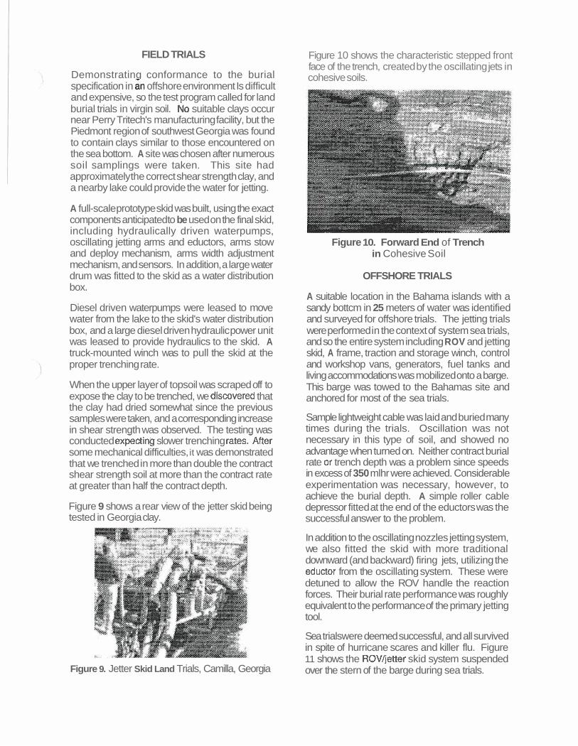
Figure 10 shows the characteristic stepped front face of the trench, created by the oscillating jets in cohesive soils.
Figure 10. Forward End of Trench in Cohesive Soil
OFFSHORE TRIALS
A suitable location in the Bahama islands with a sandy bottcm in 25 meters of water was identified and surveyed for offshore trials. The jetting trials were performed in the context of system sea trials, and so the entire system including ROV and jetting skid, A frame, traction and storage winch, control and workshop vans, generators, fuel tanks and living accommodations was mobilized onto a barge. This barge was towed to the Bahamas site and anchored for most of the sea trials.
Sample lightweight cable was laid and buried many times during the trials. Oscillation was not necessary in this type of soil, and showed no advantage when turned on. Neither contract burial rate or trench depth was a problem since speeds in excess of 350 mlhr were achieved. Considerable experimentation was necessary, however, to achieve the burial depth. A simple roller cable depressor fitted at the end of the eductors was the successful answer to the problem.
In addition to the oscillating nozzles jetting system, we also fitted the skid with more traditional downward (and backward) firing jets, utilizing the eductor from the oscillating system. These were detuned to allow the ROV handle the reaction forces. Their burial rate performance was roughly equivalent to the performance of the primary jetting tool.
Sea trialswere deemed successful, and all survived in spite of hurricane scares and killer flu. Figure 11 shows the ROVJjetter skid system suspended over the stern of the barge during sea trials.
Figure 11. ROV Skid System at Sea Trials
CONCLUSIONS
A letting system design for post lay cable burial has been conducted. Deslgn techniques and tools have been extended and verified for use on the next system. Hardware has been tested and found adequate.
The system has proven successful in all phases of its conformance trials. It is installed on a Gable and Wireless (Marine) cableship and has completed two successful missions to date in depths to 1400 meters. It has buried 10 kilometers of cable to date.
REFERENCES
Crow, S.C. (1 973) 159 Theory of Hydraulic Rock Cutting," Int. J, Rock Mech. Min.Sci., 10,567- 584.
Gray, G. R., and Darley, H. C. H. (1980) Composition and Pmperttes of Oil Well Drilling Fluids, Fourth Edition, Gulf Publishing Company, Houston, TX.
Hurlburt, G.H., J.B. Cheung, J.M. Reichman and M.H. Marvin (1978) '[Waterjet Trenching of a Simulated Seafloor Soil" Flow Technology Report No. 115, QUEST Integrated Inc., Kent Washington.
Jumpeter, A.M. (1985) "Jet Pumps," in Pump Handbook, ed by 1.J. Karassik et al., 4.1 -4.27, McGraw-Hill, New York.