PRACTICAL RESEARCH IN PROCESSING SCIENCE Development of Aerospace Materials Using Integrated Numerical and Physical Simulation BRUCE F. ANTOLOVICH , 1,2 ANTHONY BANIK, 1 JOHN W. FOLTZ, 1 JOHN V. MANTIONE, 1 and RAMESH S. MINISANDRAM 1 1.—ATI Specialty Materials, Monroe, NC 28110, USA. 2.—e-mail: bruce.antolovich@ atimetals.com The introduction of new alloys and process improvements that promise in- creased material performance to the aerospace and defense industries is a long and costly venture due to ensuring flight safety by way of data analysis and field service. Changes to the supply chain require the use of a phased ap- proach, typically technical readiness level (TRL), to reduce risk. The tech- niques in the TRL methodology include both physical simulation, such as demonstrators, and computational simulation within the Integrated Compu- tational Materials Engineering (ICME) framework. The typical approach consists of designing a methodology using computational processing, con- ducting pilot-scale trials, and using a TRL approach for scaling the technology. A balanced combination of physical and numerical simulations aids in understanding the role of metalworking processes in microstructure and property development. This in turn ensures the development of new and im- proved products in an accelerated manner. This paper reviews simulation methods, both computational and physical, available in the metals industry and discusses examples of how the use has accelerated deployment of new products. INTRODUCTION To ensure both process robustness and flight safety, new alloys and process improvements in the aerospace and defense industries are generally long and costly ventures. Changes to the supply chains incorporate a phased or technical readiness level (TRL) approach, which reduces uncertainty of a product’s service readiness. Included in this TRL approach can be both numerical and physical simulations, the former wide- spread and the latter still used in systems like aerodynamic wind tunnels. Physical simulations of metalworking processes have decreased over the past decades with a concomitant increase in the use of computational modeling. A balanced combination of physical and computational simulation processes in understanding metalworking and its role in microstructure and property development is critical to ensure swift development of new and improved products. TRLs were adopted across the aerospace industry after NASA first documented it as a tool in 1989, 1 and expanded when ISO 16290 2 was published in 2013 to standardize it for space hardware. Similar tools, such as tool maturity levels, are more focused on modeling tools and the integrated computational materials engineering (ICME) approach. In all such scales, the most lagging evaluation sets the base assessment level for the program. TRL is typically described on a 1–9 scale, with 1 representing a new idea with only basic principles observed, and 9 having demonstrated flight worthi- ness through successful missions. For material providers who produce metal products, like sheet, billet, bar, and plate, the development work for a new material or process occurs in TRL 1–5. Advanced materials companies such as ATI rou- tinely employ both physical and computational simu- lation to determine the viability of concepts and theories at low TRL levels. The priorities for develop- ing new products and processes are determined based on customer need. The use of a judicious mix of subscale physical trials (models) and computational (Received June 15, 2020; accepted July 28, 2020; published online August 18, 2020) JOM, Vol. 72, No. 10, 2020 https://doi.org/10.1007/s11837-020-04319-w Ó 2020 The Minerals, Metals & Materials Society 3570
Transcript
PRACTICAL RESEARCH IN PROCESSING SCIENCE
Development of Aerospace Materials Using IntegratedNumerical and Physical Simulation
BRUCE F. ANTOLOVICH ,1,2 ANTHONY BANIK,1 JOHN W. FOLTZ,1
JOHN V. MANTIONE,1 and RAMESH S. MINISANDRAM1
1.—ATI Specialty Materials, Monroe, NC 28110, USA. 2.—e-mail: [email protected]
The introduction of new alloys and process improvements that promise in-creased material performance to the aerospace and defense industries is a longand costly venture due to ensuring flight safety by way of data analysis andfield service. Changes to the supply chain require the use of a phased ap-proach, typically technical readiness level (TRL), to reduce risk. The tech-niques in the TRL methodology include both physical simulation, such asdemonstrators, and computational simulation within the Integrated Compu-tational Materials Engineering (ICME) framework. The typical approachconsists of designing a methodology using computational processing, con-ducting pilot-scale trials, and using a TRL approach for scaling the technology.A balanced combination of physical and numerical simulations aids inunderstanding the role of metalworking processes in microstructure andproperty development. This in turn ensures the development of new and im-proved products in an accelerated manner. This paper reviews simulationmethods, both computational and physical, available in the metals industryand discusses examples of how the use has accelerated deployment of newproducts.
INTRODUCTION
To ensure both process robustness and flight safety,new alloys and process improvements in the aerospaceand defense industries are generally long and costlyventures. Changes to the supply chains incorporate aphased or technical readiness level (TRL) approach,which reduces uncertainty of a product’s servicereadiness. Included in this TRL approach can be bothnumerical and physical simulations, the former wide-spread and the latter still used in systems likeaerodynamic wind tunnels. Physical simulations ofmetalworking processes have decreased over the pastdecades with a concomitant increase in the use ofcomputational modeling. A balanced combination ofphysical and computational simulation processes inunderstanding metalworking and its role inmicrostructure and property development is criticalto ensure swift development of new and improvedproducts.
TRLs were adopted across the aerospace industryafter NASA first documented it as a tool in 1989,1
and expanded when ISO 162902 was published in2013 to standardize it for space hardware. Similartools, such as tool maturity levels, are more focusedon modeling tools and the integrated computationalmaterials engineering (ICME) approach. In all suchscales, the most lagging evaluation sets the baseassessment level for the program.
TRL is typically described on a 1–9 scale, with 1representing a new idea with only basic principlesobserved, and 9 having demonstrated flight worthi-ness through successful missions. For materialproviders who produce metal products, like sheet,billet, bar, and plate, the development work for anew material or process occurs in TRL 1–5.
Advanced materials companies such as ATI rou-tinely employ both physical and computational simu-lation to determine the viability of concepts andtheories at low TRL levels. The priorities for develop-ing new products and processes are determined basedon customer need. The use of a judicious mix ofsubscale physical trials (models) and computational
(Received June 15, 2020; accepted July 28, 2020;published online August 18, 2020)
JOM, Vol. 72, No. 10, 2020
https://doi.org/10.1007/s11837-020-04319-w� 2020 The Minerals, Metals & Materials Society
modeling can greatly accelerate the developmentcycle, as compared with using either computationalor physical modeling alone.
In the aerospace industry, it is not uncommon fornew alloys to take 5–15 years to be introduced intoservice. A good example is gamma-TiAl, which wasfirst examined by McAndrew and Kessler in 1956,3
and was only first flight-qualified in 2007 in the GEnxengine.4 This long delay was due primarily to poorroom-temperature ductility. A more typical customer-driven example was the introduction of Ti-5Al-5Mo-5V-3Cr-0.5Fe (Ti-5553), which was publicly intro-duced in 19975 and was first used on the 787 Dream-liner in 2009.6 The 12-year development period wasdespite Ti-5553 being a derivative of VT-22, an olderRussian alloy. A more recent example is that of theengine disc alloy, Rene 65 (based on the older GE alloyRene 88), where it took the GE-ATI team only about5 years from TRL 1 to insertion in service.
This paper will review simulation methods, bothcomputational and physical, available in the metalsindustry and discuss examples of how their use canaccelerate deployment of new products.
METHODS OF PHYSICAL SIMULATION
The use of physical simulation has a long historyin the field of materials science. It pre-dates thewidespread use of numerical methods, such ascomputational fluid dynamics (CFD) and finiteelement analysis (FEA), and continues to be arelevant tool to this day.
Physical simulations can range in size fromlaboratory to full scale. The definition of size scalesdepends greatly upon the industry being served.Laboratory-scale physical simulations often involvemicro-compression or tensile frames and arc melt-ing button furnaces, which are quick ways to testnew compositions or the impact of process changes.
Among metals producers in the aerospace supplychain, a pilot plant may be used to physicallysimulate almost every full-scale process step. Thisincludes melting, remelting, open-die forging, roll-ing, and extrusion. For powder-based materials,additional processing steps are needed, such asatomization, sieving or screening, blending, andconsolidation. Typical equipment for each of thesesteps is shown below by process.
Melt
Primary melting can be accomplished in air,under a protective atmosphere or under vacuumconditions. Laboratory-scale button melting fur-naces produce 1–5 lb. (0.5–2.25 kg), and pilot-scalemelting furnaces typically melt between 50 and500 lb. (23,230 kg) of material. A pilot-scale vacuuminduction melting furnace is shown in Fig. 1.
Remelt
The ingot from a primary melt process (such asVIM) is usually remelted to remove unwanted
contamination such as trace elements and inclu-sions. Remelting may be accomplished either undera vacuum (vacuum arc remelting; VAR), under aprotective slag (electroslag remelting; ESR) or both.These processes use the ingot cast in a prior processas a consumable electrode for the remelt process. Apilot-scale VAR furnace is shown in Fig. 2.
Press
Pilot-scale open die presses are commonly used toperform upset forging to evaluate workability andrefine microstructure, as well as to simulate multi-ple hit/multiple reheat billet conversion (cogging)processes. The aerospace community employs forgepresses with load capacities between 100 and 1000tons (91 and 917 metric tonnes), which range insophistication from hand-operated presses to thosethat are computer-controlled with automated data
Development of Aerospace Materials Using Integrated Numerical and Physical Simulation 3571
acquisition. Figure 3 shows an example of such apress.
Rolling
Benchtop scale bar rolling simulation, usingsmall-scale rolls and colored modeling clay or softmetals, can be operated with a hand-crank. Con-centric layers of differing model clay colors allowdirect measurement of deformations, and calcula-tions of strains.
Pilot-scale rolling mills with either a two-high orfour-high configuration are used to evaluate work-ability. The equipment is sized to accept input up ofapproximately 2 9 2 9 4 in. (width, thickness,length) in. (50 9 50 9 100 mm). Like forge presses,the equipment ranges from completely manual tofully automated and instrumented.
Extrusion
Pilot-scale extrusion presses are less common andhave been used to develop new materials and tounderstand the effects of die geometry upon diewear and strain distributions with round or shapedworkpieces.
Small-scale simulation of extruded rounds,approximately 2-in. (c.50-mm) diameter, have beenconducted in order to physically predict strainfields. To map the strain, billets are cut longitudi-nally to half-circle cross-sections, marked along themidplane with a grid, and either co-extruded orextruded in a half-circle shape with the planar facealigned with the grid on the entering material. Afterextrusion, the shape of the grid is used to reveal thestrain patterns within the material.
Atomization
Atomization at pilot-scale is a difficult process tomodel physically, primarily due to size-scale effects
during solidification. The size of these installationsdepends upon the material and industry; nickelbase superalloys typically have pilot-scale atomiza-tion units capable of producing 2–200 lb (1–100 kg)of powder per run. Pilot-scale can use full-scaleatomizing nozzles with smaller melt and atomiza-tion chambers. These units often have high-speedphotography through viewports to characterize theatomization process and the impact of processparameters on the powder produced. Figure 4shows a pilot-scale atomization unit. Powder han-dling can also be simulated, including screening/sieving, blending, and container loading technology.
Gas atomization of metal is another examplewhere the kinematic similarity of water to moltenmetal makes it a particularly adept material sub-stitute. As we will see later, it also makes anexcellent material substitute for other metallicliquid processes, such as water modeling oftundishes.
Atomization with water benches consists of anatomization head unit installed in a transparentplastic enclosure using air as the atomizing gas.High-speed photography is used to record the shapeof the atomization plume as well as the character-istics of the formed water droplets, which makes itvery good for studying the atomization processthough not droplet solidification. Low melting pointmaterials can be used for the latter, and whilesignificantly easier to handle than other metals,they still require significantly more sophisticatedequipment than the water due to maintaining aconstant temperature supply of liquid material.
Hot Isostatic Pressing (HIP)
Small-scale hot isostatic pressing is commonamong both industry and academia given the
Fig. 3. Pilot-scale 1000-ton (907-metric tonne) forging press.Courtesy ATI Specialty Materials. Fig. 4. Atomization unit and cooling tower.
Antolovich, Banik, Foltz, Mantione, and Minisandram3572
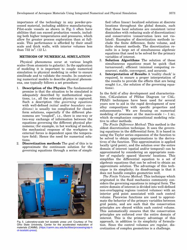
importance of the technology in any powder-pro-cessed material, including additive manufacturing.Pilot-scale vessels as shown in Fig. 5 often haveabilities that can exceed production vessels, includ-ing both higher temperatures and pressures, whichallow for greater process exploration than at full-scale. This performance is afforded by their smallscale and thick walls, with interior volumes lessthan 732 in3. (12 L).
METHODS OF NUMERICAL SIMULATION
Physical phenomena occur at various lengthscales (from atomistic to galactic). In the applicationof modeling it is important to couple numericalsimulation to physical modeling in order to ensuresimilitude and to validate the results. In construct-ing numerical models to describe physical phenom-ena, one typically follows a set procedure:
1. Description of the Physics The fundamentalpremise is that the situation to be simulated isadequately described by mathematical equa-tions, i.e., all the relevant physics is captured.Such a description (the governing equationswith well-defined initial and/or boundary con-ditions) is usually too complicated for closed-form solutions, especially if the different phe-nomena are ‘‘coupled’’, i.e., there is one-way ortwo-way exchange of information between theequations governing the different physical phe-nomena; (for example, in hot working of metals,the mechanical response of the workpiece toexternal forces is dependent upon the tempera-ture field). Hence the need for numerical solu-tions.
2. Discretization methods The goal of this is toapproximate the continuum solution for thegoverning equations through a series of simpli-
fied (often linear) localized solutions at discretelocations throughout the global domain, suchthat these local solutions are consistent (errordiminishes with reducing scale of discretization)and conservative (conservation laws not vio-lated). Examples of discretization methods in-clude the finite difference, finite volume, andfinite element methods. The discretization re-sults in a large set of simultaneous algebraicequations that need to be solved for the primaryvariables of interest.
3. Solution Algorithms The solution of thesesimultaneous equations must be quick (fastturnaround), efficient (minimal computing re-sources), stable, convergent, and accurate.
4. Interpretation of Results A ‘reality check’ isrequired, to ensure a proper interpretation ofthe results to provide the effects that are beingsought (i.e., the solution of the governing equa-tions).
In the field of alloy development and characteriza-tion, CALculation of PHAse Diagram (or CAL-PHAD) techniques have been used for severalyears now to aid in the rapid development of newalloy compositions with specific properties andenhancements.7 We are focusing on numericalmodeling of processes at the macro-scale (� 1 m),which de-emphasizes compositional modeling rela-tive to other methods.
The Finite Difference Method: This method is theoldest discretization technique. It uses the govern-ing equations in the differential form. It is based inusing the Taylor series expansion of the function tobe solved to obtain approximations to the deriva-tives of the function. This approximation is appliedlocally (grid point), and the solution over the entiredomain of interest (spatial and/or temporal) can beapproximated by considering an appropriate num-ber of regularly spaced ‘discrete’ locations. Thissimplifies the differential equation to a set ofalgebraic equations that can be solved to obtain anapproximate solution. The advantage of this tech-nique is its simplicity; its disadvantage is that itdoes not handle complex geometries well.
The Finite Volume Method: This technique whichoriginated in the fluid mechanics community con-siders the governing equations in integral form. Theentire domain of interest is divided into well-definednon-overlapping regions (control volumes) with aninterior grid point associated with each controlvolume. Piecewise functions are used to approxi-mate the behavior of the primary variables betweengrid points, and are such that the conservationprinciples are obeyed within each control volume.This automatically ensures that the conservationprinciples are enforced over the entire domain ofinterest. This is the primary advantage of thisapproach, in addition to its simplicity of formula-tion. Since the control volumes are regular, dis-cretization of complex geometries is a challenge.
Fig. 5. Laboratory-scale hot isostatic press unit. Courtesy of TheOhio State University, Center for the accelerated maturation ofmaterials (CAMM); (https://camm.osu.edu/facilities/processing/aip-hot-isostatic-press).
Development of Aerospace Materials Using Integrated Numerical and Physical Simulation 3573
The Finite Element Method: In this method, thedomain of interest is sub-divided into a collection ofnon-overlapping geometric shapes; the ‘finite ele-ments.’ Piecewise functions are used to describe thebehavior of the primary variables within eachelement, and the governing equations formulatedfor each element using the approximate functions.The primary advantage of the technique is theability to handle complex geometries, as well as theability to use techniques such as adaptive meshrefinement (locally finer meshing and/or higherorder interpolations). The disadvantage of the finiteelement method is that the formulation and imple-mentation are complicated.
Since the early 1970s, several commercial numer-ical packages have been in use to perform thediscretization and solution steps listed above. CFDcodes, such as ANSYS-FluentTM and COMPACT/MeltFlowTM, are based on the control volumeapproach, while the solid mechanics codes, such asAbaqusTM and DEFORM�, have chosen the FEAapproach.
In the aerospace industry, the use of numericmodels that have been validated with advancedcharacterization and physical models provides a keylink to production scale. No matter the approach, akey aspect of such solutions was noted by Bertramet al.8, in the context of modeling the VAR process:
To a degree hard to overstate, most of theproblem definition is contained in … boundaryconditions.
EXAMPLE CASES OF INTEGRATEDMODELING
The integration of physical modeling along withcomputational modeling results in a greater refine-ment of both models, a deeper understanding of thephysical systems and boundary conditions, andoften a unique combination of speed and accuracyunparalleled by either singular technique. Thefollowing are examples where both efforts wereused in combination to great success.
Case 1: Development of Extruded TitaniumShapes
Structural members of airframes can be made bya variety of methods, ranging from machining frommill products such as plate or forgings, to extrudingcomplex shapes. The cost ranges are based on theefficiency, or the ‘‘buy to fly’’ ratio, of manufacturingthe part from each method. Extruding shapesrather than machining from blocks often results ina lower installed cost.
Designing tooling for extruded titanium shapes isa challenging, iterative process given the highstrain rates, thermal gradients, and large plasticstrains involved. The time and cost of developingthese shapes is reduced through computational and/
or physical modeling. ATI has manufacturedextruded titanium shapes and used finite elementmodeling to generate and digitally assess diedesigns. The digital design process also enabledmachine shops to automatically design machiningand inspection paths for the extrusion dies.
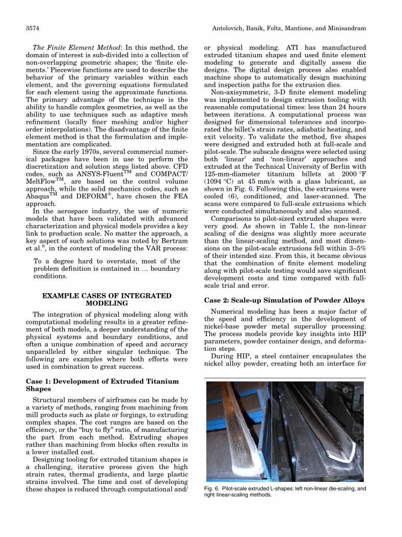
Non-axisymmetric, 3-D finite element modelingwas implemented to design extrusion tooling withreasonable computational times: less than 24 hoursbetween iterations. A computational process wasdesigned for dimensional tolerances and incorpo-rated the billet’s strain rates, adiabatic heating, andexit velocity. To validate the method, five shapeswere designed and extruded both at full-scale andpilot-scale. The subscale designs were selected usingboth ‘linear’ and ‘non-linear’ approaches andextruded at the Technical University of Berlin with125-mm-diameter titanium billets at 2000 �F(1094 �C) at 45 mm/s with a glass lubricant, asshown in Fig. 6. Following this, the extrusions werecooled (6), conditioned, and laser-scanned. Thescans were compared to full-scale extrusions whichwere conducted simultaneously and also scanned.
Comparisons to pilot-sized extruded shapes werevery good. As shown in Table I, the non-linearscaling of die designs was slightly more accuratethan the linear-scaling method, and most dimen-sions on the pilot-scale extrusions fell within 3–5%of their intended size. From this, it became obviousthat the combination of finite element modelingalong with pilot-scale testing would save significantdevelopment costs and time compared with full-scale trial and error.
Case 2: Scale-up Simulation of Powder Alloys
Numerical modeling has been a major factor ofthe speed and efficiency in the development ofnickel-base powder metal superalloy processing.The process models provide key insights into HIPparameters, powder container design, and deforma-tion steps.
During HIP, a steel container encapsulates thenickel alloy powder, creating both an interface for
Antolovich, Banik, Foltz, Mantione, and Minisandram3574
creep-based consolidation under hydrostatic pres-sure and an interface with vastly different yieldstrength and density than the material within. Asindicated in Fig. 7, thermal history is location-dependent, so computational simulation is neces-sary to understand the temperature profile of thefull-scale powder compact and how to replicate thebehavior on the subscale. This demonstrates thesynergies of numeric and physical simulations.
Integration of the subscale activities into produc-tion-scale processes are important validation steps.As indicated in the powder development activity onan advanced nickel-base superalloy, the processsimulation applied to full-scale effectively predictedloading within 5% of actual (Fig. 8).
Once the physical and numerical modeling iscomplete, the entire package provides insight intosetting up the full-scale production manufacturingroute. As indicated in Fig. 9, full-scale superalloypowder billets have been successfully produced fromsome of the most complex and advanced nickel-basesuperalloys.
Case 3: Understanding Pool Stirring
Vacuum arc remelting is the crucial final step forthe manufacture of both superalloy and titaniumingots used in aerospace applications. Figure 10shows a schematic of the VAR furnace, and Table IIcompares the nominal melt practice for a superalloysuch as alloy 718 with Ti-6Al-4V. The key differencein VAR practices is the use of magnetic steeringcoils in the case of titanium melting. A square-waveDC-current solenoidal magnetic field is applied tothe process to control arc motion (arc-steering),which helps to contain the plasma arc under theshadow of the electrode. Typically, the current inthe solenoid is periodically reversed so that the fielddirection in the furnace alternates up and downalong the ingot axis. In addition to its effect on thearc, the reversing magnetic field also induces meltpool stirring. The reversal of the stirring fieldinduces a periodic rotation/counter rotation of thepool, analogous to a washing machine. The exactimpact of this pool stirring on the pool depth hasbeen studied using CFD models, and the results
from various models have differed enough that noconclusions could be drawn. The melting of pilot-scale VAR ingots offers a convenient and low-costalternative means of answering this question dur-ing alloy development.
For this study, 6-in. (150-mm)-diameter elec-trodes of alloy 718 were VAR-melted into 8-in.(200-mm)diameter crucibles using a melt current of3000 A. In each case, the steady-state pool wasmarked just prior to turning off the power at the endof the melt. The pool was marked by inserting about0.5 lb. (227 g) of tungsten bits into the electrode,which entered the melt pool as the electrode meltedup to the location of the tungsten. The tungstendispersed and marked the bottom of the poolbecause it sinks due to its higher density. Ingotswere manufactured for three conditions:
� No stirring.� Stirring with field strength of 45 G, with field
reversing every 7 s.� Stirring with field strength of 45 G, with field
reversing every 59 s.
After VAR, the ingots were sectioned longitudinallyand etched to reveal the macrostructure of theentire ingot. Figure 11 illustrates the results ofthese trials in terms of the VAR pool depth andmacrostructure. The left ingot in Fig. 11 is theunstirred ingot, the pool depth is 5.5 in. (140 mm),
Table I. Percentage of data points that once re-scaled were within 1%, 3%, or 5% of the full-scale dimension.
Shape number Scaling method Within 1% Within 3% Within 5%
1 Linear 54.6 72.7 72.7Nonlinear 88.9 100 100
2 Linear 11.1 55.6 100Nonlinear 44.4 100 100
3 Linear 35.7 71.4 100Nonlinear 75.0 100 100
4 Linear 28.6 64.3 85.7Nonlinear 85.7 92.9 100
5 Linear 12.5 75.0 100Nonlinear 100 100 100
Fig. 7. Models for heat transfer during HIP become important factorsin defining subscale physical models.
Development of Aerospace Materials Using Integrated Numerical and Physical Simulation 3575
and the macrostructure is typical of the VAR ingotwith columnar grains growing perpendicular to theliquid pool. The middle ingot in Fig. 11 is the stirredingot with a 7-s reversal time, and both pool andstructure are similar to the unstirred ingot with no
appreciable change in the measured pool depth(5.6 in. or 142 mm); however, the shape of the poolis more conical, with straighter side walls. The thirdingot was stirred with a 59-s reversal and showsmore distinct differences in having a 25% deeper
Fig. 8. The model simulation related well with the actual upset billet.
Fig. 9. (a) Final forging of full-scale 10 in. (254 mm)-diameter nickel superalloy billet; (b) uniform fine grain (ASTM 13).
Fig. 10. Left Schematic of VAR furnace, right schematic of melting titanium and superalloy in production compared with pilot plant.
Antolovich, Banik, Foltz, Mantione, and Minisandram3576
pool (6.9 in. or 175 mm), and a macrostructureshowing a distinct banding pattern, the periodicityof which corresponds to the reversal frequency ofthe stirring field.
The differences in pool configuration may beexplained as follows. In the case of the unstirredingot, there is no appreciable flow in the azimuthaldirection. In the middle case, with the fast reversalof 7 s, the azimuthal velocity field is just establish-ing at the instant of reversal, as inferred by thestraighter side walls. In the case of the third ingot, aslow reversal time of 59 s provides enough time forthe azimuthal velocity field to fully establish,resulting in enough motion to significantly deepenthe pool before reversal. The results also provide acautionary lesson about the need for numericalmodels to incorporate all the relevant physics, aswell as well-defined boundary conditions, as aplausible explanation for the differing results fromvarious CFD models alluded to earlier.
Case 4: Evaluation of Ti Ingot Conversion
Open die forging is the most common method ofrefining cast grain structures of ingots into a
suitable fine-grain structure as input for otheroperations or final product—the so-called cast-wrought process. In the aerospace industry, theforging process has near-limitless combinations ofprocess parameters which are optimized for perfor-mance, cost, and throughput, given the multiplethermomechanical cycles involved for every pro-duct, as illustrated in Fig. 12. Integration of sub-scale physical models with computational modelsshortens the optimization cycle; an example is therefinement optimization of Ti-6Al-4V microstruc-ture from a nominal 36 in. (915 mm) diameter ingotto a 10 in. (255 mm) diameter billet, which wasmodeled as individual upset and draw forging stepsat pilot-scale. Once the desired microstructure wasachieved at a 3 1/8 in. (80 mm) diameter billet in thesubscale physical model (Fig. 13), that process wasanalyzed using commercially available FEA soft-ware (Fig. 14), and the full-scale process was thendeveloped with the pilot-scale digital and physicalmodels as guides. By mapping each thermo-me-chanical subscale step to a full-scale step withequivalent output state variables in the computa-tional model, the model was validated and the
Table II. Differences schematically between superalloy and titanium melting.
Alloy 718 Ti-6Al-4V
Ingot diameter �20 in. (0.5 m) �35 in. (0.9 m)Criterion for current/melt rate le-vels
Mitigate the formation of melt de-fects
Safely maximize productivity
Arc steering Not used Used to control the arc, creating a safeprocess
Fig. 11. Results of pool marking trials for 8 in. (200 mm) diameter. Pilot-scale vacuum-arc remelted ingots. The ingot on the left was not stirred;the ingot in themiddle was stirred with a field reversal of 7 s; the ingot on the right was stirred with a field reversal of 59 s. In each case, the dottedlines depict the melt pool.
Development of Aerospace Materials Using Integrated Numerical and Physical Simulation 3577
optimization process was achieved with a single full-scale trial, demonstrating equivalence between thesubscale and full-scale microstructure (Fig. 15).
Case 5: Simulation of Liquid Metal Flow
Metal cleanliness is critical to material perfor-mance, such as fatigue resistance and improvedsafety. Pilot-scale tundish simulations can usewater as a model material to physically simulatefluid dynamics and are common in the steel indus-try. These simulations can help to ensure metalcleanliness across alloy systems, through inclusionentrapment by establishing latency times for fluidflow that ensures adequacy of density-based sepa-ration. This aids in the optimization of dams andweirs in full-scale installations. Pilot-scale canconsist of 10–50% the size of full-scale installations,and the Froude number ensures dynamic
similarity.9 Dyes can typically track fluid flow, andgelatin capsules can simulate inclusions. Construc-tion from transparent plastics allows the recordingof results using video cameras, as shown in Fig. 16,where the water model in combination with an airjet was used to simulate the flow of liquid titaniumand the trajectories of inclusion particles in thehearth of a plasma arc cold hearth furnace.10
Particle counters on the exiting product can provideinsight into the effectiveness of various weir anddam configurations.
Case 6: Process Development of Rene 65
Powder metal superalloys have made significantadvances into the turbine sections of both militaryand commercial propulsion engines. As a result,conventional melted (VIM + VAR or VIM + ESR +VAR) alloys such as ATI 718TM, and ATI 720TM
0
500
1000
1500
2000
0 4 8 12 16 20
Tempe
rature
(F)
Processing (hours)
BetaBreakdown
Upset+
Draw
Alpha/BetaPrestrain
Draw
FinalBeta
Draw+
WQ
FinalAlpha/Beta
Upset+ Draw
BetaTransus
Fig. 12. Representative thermo-mechanical process map for Ti-6Al-4V demonstrating the four major process cycles and their input controls,including: duration, temperature, heat-up rate, cool-down rate and deformation orientation (upset in z-axis or draw in the x-axis.
Fig. 13. Pilot-scale cogging of a Ti-6Al-4V billet at 140 mm diameter on a 1000-ton (907-metric tonne) hydraulic press, and the resultingmicrostructure revealed by Kroll’s etchant.
Antolovich, Banik, Foltz, Mantione, and Minisandram3578
grades are being replaced with powder alloys, Rene88, Rene 104 and RR1000. Phase stability modelingand compositional adjustments can be analyzed toreduce the sensitivity to solidification segregation orenable greater recyclability of these or other nickel-based superalloys.
Rene 65 was developed as a derivative from Rene88DT, and features higher iron content and con-trolled carbon and nitrogen to assist in recycling.These advanced alloys have a high propensity forcracking (Fig. 17), and their processing can beoptimized using computational models in combina-tion with pilot-scale physical simulations. To accom-plish this in Rene 65, subscale ingots were press-converted through initial hotworking operations,and the final microstructure was generated usingroll deformation.
Through combined models, the cracking can belinked to strain and temperature distributions. Likein the titanium case presented, iterative modelingphysically and computationally allows for bettermodel refinement and sooner product offerings(Figs. 18, 19). Rolling operations were performedon the subscale billets after press conversion, anddemonstrated refined, uniform grain size (Fig. 20).
With the use of integrated subscale equipmentand numerical modelling, process conditions toincrease scaling from a 1¼-in. (32-mm) bar to a10-in. (250-mm)-diameter billet can be accomplishedwith a significantly shorter development cycle fornew alloys. In the case of Rene 65, it permitted thetailoring of the composition of an existing powderalloy, Rene 88, and the modification of the processroute for ingot metallurgy processing to provide alower cost alternative for advanced aeroengines.
Fig. 14. The effective strain distribution of a 130-mm-diameter billetlongitudinal cross-section after subscale thermo-mechanicalprocessing as simulated by the cogging model available inDEFORM-3D�.
Fig. 15. Full-scale cogging of a Ti-6Al-4V ingot of 915 mm diameter on a 10,000-ton (9070-metric tonne) hydraulic press, and resultantlongitudinal microstructure revealed along the centerline with Kroll’s etchant.
Fig. 16. Water model for the physical simulation of molten metal flowthrough a tundish or hearth.
Development of Aerospace Materials Using Integrated Numerical and Physical Simulation 3579
Fig. 17. Dwell time and reduction were identified as critical parameters using subscale deformation modeling and experimental testing.
Fig. 18. Subscale macrostructural response can be used to refine model parameters prior to moving into full-scale development. The finiteelement map on the left plots effective strain, which is also observed with the macrostructure after etching.
Fig. 19. Refined macrostructure and microstructure through pilot conversion.
Fig. 20. Samples obtained from the bar ends exhibited a uniform macrostructure and microstructure.
Antolovich, Banik, Foltz, Mantione, and Minisandram3580
CONCLUSION
Integrated computational materials engineeringmost commonly refers to the joining of computa-tional models at various length scales or levels ofcomplexity. The combination of numerical andphysical simulation is another example of how theICME philosophy can be applied, and which hasbeen shown to be potent in reducing both the timeand the expense of the development of new orimproved materials and processes. This combina-tion allows the reduction of development iterations,leading to accelerated entry into the market of bothtitanium- and nickel-base alloy systems. For com-mercial alloy systems, the development cycle hasbeen reduced by up to 5 years. Ultimately, thetimely introduction of new materials and processingimprovements contributes significantly to airlinesafety, improved defense capabilities, and improvedeconomic performance of the aerospace sector as awhole. Aerospace industry trends include a contin-ued focus on safety and cost, and therefore ICMEapproaches will remain in the forefront in theefforts to improve materials.
ACKNOWLEDGEMENTS
We would like to particularly thank andacknowledge the great and long-lasting contribu-tions made by S. Lee Semiatin and Wei-Tsu Wu overthe course of their long careers. Both have madewell-known and significant contributions to thecombined use of physical and computational simu-lation.
CONFLICT OF INTEREST
On behalf of all authors, the corresponding authorstates that there is no conflict of interest.
REFERENCES
1. S.R. Sadin, F.P. Povinelli, and R. Rosen, Acta Astronaut. 20,73 (1989).
2. International Organization for Standardization, ISO16290:2013 (2013).
3. J.B. McAndrew and H.D. Kessler, J. Met. 8, 1348 (1956).4. N. Bewlay and W. Suzuki, Mater. High Temp. 33, 549
(2016).5. J.C. Fanning, R.R. Boyer, Proceedings of the 10th World
Conference on Titanium (2003), pp. 2643–2650 .6. Boeing 787 Dreaminer completes first flight (2009), https://b