Page 1
MONTANUNIVERSITÄT LEOBEN Franz-Josef-Straße 18
A-8700 Leoben
Masterarbeit
Development of an analytical method for determination of rare
earth elements in rock samples by HPIC-ICP-MS
erstellt am
Lehrstuhl für Allgemeine und Analytische Chemie, Montanuniversität Leoben
Vorgelegt von: Betreuer/Gutachter: Estephany Janette Marillo Sialer Ao.Univ.Prof.Mag.rer.nat.Dr.mont. Thomas Meisel
0635330
Leoben, Juni 2010
Page 2
EIDESSTATTLICHE ERKLÄRUNG
Ich erkläre an Eides statt, dass ich diese Arbeit
selbständig verfasst, andere als die angegebenen
Quellen und Hilfsmittel nicht benutzt und mich auch
sonst keiner unerlaubten Hilfsmittel bedient habe.
AFFIDAVIT
I declare in lieu of oath, that I wrote this thesis and
performed the associated research myself, using
only literature cited in this volume.
Datum Unterschrift
Page 3
AKNOWLEDGEMENTS
I would like to thank all the people who have helped me in many and various ways
to complete this work.
First, I would like to thank my advisor Mag. Dr. Thomas Meisel for showing me the
insights of his field of work. Without his guidance and support throughout the whole
process, this thesis would not have been a reality.
I would also like to express my gratitude to Marleen Hennig for the feedback given
during various stages of this work and for her support in conducting laboratory
experiments.
I wish to acknowledge Imran Irfan for his help in preparing samples for analysis,
and Stefan Vollgger and Diego Herrera for their help in solving some software
issues.
To all the members of the Department of General and Analytical Chemistry and the
Institute of Sustainable Waste Management and Technology, thanks for the good
working atmosphere.
I also gratefully acknowledge to the members of the OeAD Branch Office Leoben
for the granting of an educational scholarship which helped me greatly in the first
years of my studies.
Dedicated to my parents and brother
Page 4
Kurzfassung
Methodenentwicklung zur Bestimmung von Lanthaniden in geologischen Proben mittels HPIC-ICP-MS
Die Arbeit befasst sich mit der Optimierung einer analytischen Methode zur Feststellung der
14 natürlich auftretenden Lanthanide in geologischen Proben. Die vorgeschlagene Methode
beruht auf einer Sinterung mit Natriumperoxid (Na2O2) nach Zusetzung einer Thulium
Spikelösung. Weiters wird die Kationenaustauschtrennung der Lanthanide von den
Matrixelementen sowie die Bestimmung einzelner Seltener Erden unter Verwendung eines
gekoppelten HPIC-ICP-MS behandelt.
Zur Trennung der Seltenen Erden sowie Entfernung von Matrixelementen kam das Dowex
50W-X8 Kationenaustauschharz zum Einsatz. Die Lanthanide wurden separiert, um
spektrale Interferenzen der polyatomaren Ionen (speziell BaO+) bei der ICP-MS Messung zu
verhindern und die Signalunterdrückung zu minimieren. Die effizienteste Trennung konnte
mit Hilfe einer sauren Elution erreicht werden, wobei die Matrixelemente durch eine Lösung
aus 2 mol l-1 HNO3 und einer geringen Menge Oxalsäure und die Lanthanide mit 6 mol l-1
HNO3. entfernt wurden.
Weiters wurde die Trennung und quantitative Bestimmung von Seltenen Erden mittels
Hochleistungsionenchromatographie (HPIC) unter Einsatz von Oxal- und Diglykolsäure als
mobile Phasen, geprüft. Dabei wurde der Einfluss von unterschiedlichen
Gradientenmethoden auf deren Rückhaltevermögen und der daraus schließenden Effizienz
der Trennung untersucht. Dazu wurde die IonPac® CS5A (2 x 250 mm) Ionenaustauschsäule
verwendet, wobei die optimale Gradientenmethode eine Trennung und Bestimmung der 14
natürlich auftretenden Seltenen Erden in weniger als 17 Minuten ermöglicht.
Die Gültigkeit der hier vorgeschlagenen Methode wurde durch zwei bekannte
Referenzproben, BIR-1 and BRP-1 überprüft. Dabei konnte eine generell gute
Übereinstimmung mit publizierten und zertifizierten Werten festgestellt werden.
Messungen der Proben OU-1, OPC-1, OKUM und MUH-1 zeigten zufriedenstellende
Ergebnisse mit einer Standardabweichung von 0,2 bis maximal 9% nach durchgeführter
Rohdatenkorrektur mittels Thulium. Die Messungen des Referenzmaterials sowie der Proben
unter Verwendung der vorgeschlagenen Methode lieferten gleichmäßige normalisierte
Lanthanid Kurven.
Diese Arbeit bildet die Basis für weitere Konzentrationsuntersuchungen von Lanthaniden. In
Kombination mit Isotopenverdünnung Massenspektrometrie (ID-MS) kann die geringste
Messabweichung aller derzeit verfügbaren analytischen Methoden erreicht werden.
Page 5
Abstract
Development of an analytical method for determination of rare earth elements in rock samples by HPIC-ICP-MS
The present study describes the optimization of an analytical procedure for the determination
of 14 rare earth elements (REE) in geological samples. The proposed method involves
sodium peroxide (Na2O2) sintering of sample material after addition of a Tm spike, the cation
exchange separation of the REE from matrix elements, and the determination of individual
REE by means of HPIC-ICP-MS coupling system.
The Dowex 50W-X8 cation exchange resin is used for the study of the REE group separation
and the elimination of matrix elements. The REE are separated from the bulk matrix in order
to avoid the spectral interference from polyatomic ions (in particular BaO+) in the
determination by ICP-MS and to minimize signal suppression. The most efficient separation
consisted in a nitric acid media gradient elution, where the matrix elements are removed
using 2 mol l-1 HNO3 containing a small amount of oxalic acid and the REE are eluted using 6
mol l-1 HNO3.
Furthermore, High Performance Ion Chromatography (HPIC), using oxalic acid and diglycolic
acid as mobile phase, was investigated for the separation and the quantitative determination
of rare earth elements (REE). In this matter, the influence of different gradient elution on the
retention and hence the separation efficiency of the individual REE was studied. The
separation was carried out using an IonPac® CS5A (2 x 250 mm) analytical column. The
optimum gradient elution enables the separation and determination of the 14 naturally
occurring REE in less than 17 minutes.
The validity of the proposed analytical procedure is assessed by analysis of two well
characterized Reference Materials, BIR-1 and BRP-1. REE concentration data obtained for
these reference materials are generally in good agreement with published and certified
values.
Satisfactory results were obtained in the analysis of samples (OU-1, OPC-1, OKUM and
MUH-1), including materials with low REE abundances. Relative standard deviation (RSD)
ranging from 0,2 to less than 9% were obtained after raw data correction using Tm. Smooth
REE normalized pattern were obtained for all the reference materials and samples analyzed
by the proposed analytical procedure.
This work is the basis for further REE concentration studies. In combination with isotope
dilution mass spectrometry (ID-MS), the lowest measurement uncertainties of all currently
available analytical procedures can be achieved.
Page 6
Resumen
Desarrollo de un método analítico para la determinación de tierras raras en muestras geológicas mediante HPIC-ICP-MS
El presente trabajo describe la optimización de un método analítico para la determinación de
tierras raras (lantano, La, a lutecio, Lu) en muestras geológicas. El método desarrollado
abarca desde disolución de la muestra mediante sinterizado con peróxido de sodio (Na2O2)
previa adición de una solución estándar de tulio (Tm), hasta la determinación de los analítos
utilizando un sistema de Cromatografía Líquida de Intercambio Iónico (HPIC) acoplado a un
detector ICP-MS.
La solución de la muestra se sometió a un proceso de intercambio catiónico con el fin de
eliminar la matriz y reducir las interferencias causadas por iones poliatómicos (en especial
BaO+) antes de la determinación mediante HPIC-ICP-MS. La resina Dowex 50W-X8 fue
utilizada como fase estacionaria en esta separación cromatográfica. Una óptima separación
de las tierras raras respecto a los elementos de matriz fue obtenida utilizando una elución en
gradiente de ácido nítrico. Así, los elementos de matriz fueron eluídos con una solución de 2
mol l-1 HNO3 que contenía cierta cantidad de ácido oxálico, y las tierras raras con una
solución de 6 mol l-1 HNO3.
La separación entre elementos de La a Lu se llevó a cabo mediante HPIC. Para esto se
optimizó la separación cromatográfica que utiliza la columna de intercambio iónico IonPac®
CS5A (2 x 250 mm) como fase estacionaria y una mezcla de ácido oxálico y ácido diglicólico
como fase móvil. El gradiente de elución óptimo encontrado permite la separación y
determinación de los14 elementos de tierras raras en menos de 17 minutos.
La validación del método analítico desarrollado se llevó a cabo a través de la determinación
de la concentración de tierras raras en dos materiales de referencia, BIR-1 y BRP-1. Los
valores obtenidos en las mediciones realizadas coinciden en gran magnitud con los valores
publicados y certificados de estos dos materiales.
Adicionalmente se analizaron cuatro muestras geológicas (OU-1, OPC-1, OKUM y MUH-1).
Los valores de desviación estándar relativa en las mediciones variaron entre 0,2 y 9%, luego
de la corrección respecto a la concentración de Tm en la muestra. Las curvas normalizadas
de tierras raras trazadas con las concentraciones halladas mostraron en todos los casos un
patrón regular.
El procedimiento analítico propuesto representa la base de futuros estudios en combinación
con la metodología de dilución isotópica (ID-MS). Entre todos los procedimientos analíticos
actualmente disponibles para la determinación de tierras raras, ID-MS representa aquella
con la menor incertidumbre en los resultados.
Page 7
___________________________________________________________________________________________________________________________________________________________________________________________________________
1
Table of Contents
Page
1� INTRODUCTION................................................................................................... 3�
1.1� Problem Identification ................................................................................. 3�
1.2� Goals and Targets ...................................................................................... 4�
2� GENERAL INFORMATION ON RARE EARTH ELEMENTS............................... 5�
2.1� Occurrence and Abundance....................................................................... 5�
2.2� General Chemical and Geochemical Properties of the REE ...................... 6�
2.2.1�Oxidation states and ionic radius ................................................................. 6�
2.3� Data Presentation....................................................................................... 8�
2.3.1�Chondrite normalized diagrams ................................................................... 8�
2.4� Importance of the Rare Earth Elements ................................................... 11�
3� ANALYTICAL PROCEDURE ............................................................................. 12�
3.1� Sample Preparation.................................................................................. 13�
3.1.1�Sample Decomposition Procedures ........................................................... 13�
3.2� Pre-concentration and Group Separation of Rare Earth Elements .......... 14�
3.2.1� Ion exchange chromatography................................................................... 15�
3.3� High Performance Liquid and Ion Chromatography ................................. 17�
3.3.1� Instrumentation........................................................................................... 18�
3.3.2�Stationary and Mobile Phases.................................................................... 20�
3.4� Inductively Coupled Plasma Mass Spectrometry ..................................... 21�
3.4.1�Fundamentals of ICP-MS ........................................................................... 22�
3.4.2�Analysis of REE.......................................................................................... 22�
3.4.3�Coupling of ICP-MS to a chromatographic system .................................... 25�
4� EXPERIMENTAL ................................................................................................ 26�
4.1� Materials and Reagents............................................................................ 26�
4.2� Instrumentation......................................................................................... 26�
4.3� Geological Reference Materials ............................................................... 26�
4.4� Samples.................................................................................................... 27�
4.5� Sample Preparation.................................................................................. 27�
4.6� Ion Exchange Chromatographic Group Separation.................................. 27�
4.6.1�HCl/HNO3 sequential elution ...................................................................... 29�
4.6.2�Nitric acid media......................................................................................... 29�
Page 8
___________________________________________________________________________________________________________________________________________________________________________________________________________
2
4.6.3�Detection Limits.......................................................................................... 32�
4.7� Separation and Determination of Individual Rare Earth Elements by
HPLC-ICP-MS .......................................................................................... 32�
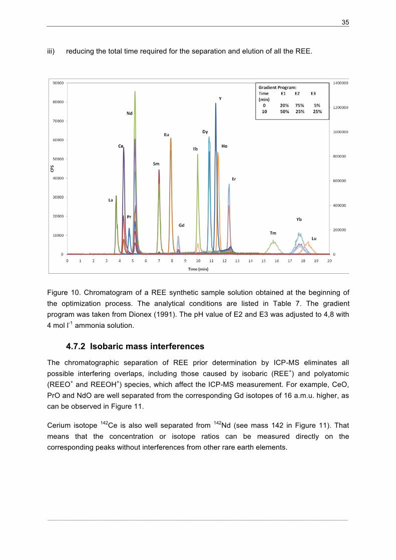
4.7.1�Separation procedure optimization............................................................. 34�
4.7.2� Isobaric mass interferences ....................................................................... 35�
4.7.3�Method Standardization ............................................................................. 36�
4.7.4�Standard Addition....................................................................................... 36�
5� RESULTS AND DISCUSSION ........................................................................... 38�
5.1� Cation Exchange Separation Elution Curves ........................................... 38�
5.1.1�HCl/HNO3 sequential elution ...................................................................... 38�
5.1.2�Nitric acid media......................................................................................... 40�
5.1.3�Blank values and detection limits ............................................................... 43�
5.1.4�Recovery and separation factors................................................................ 44�
5.2� HPIC-ICP-MS Chromatographic Data Analysis........................................ 47�
5.2.1�Separation of La, Ce, Pr and Nd ................................................................ 47�
5.2.2�Separation of elements from Sm to Lu....................................................... 48�
5.2.3�Calibration Curves...................................................................................... 52�
5.2.4�Precision and accuracy .............................................................................. 54�
5.2.5�Sample Analysis......................................................................................... 57�
5.2.6�Tm Addition ................................................................................................ 59�
6� CONCLUSION .................................................................................................... 62�
7� INDICES.............................................................................................................. 63�
7.1� References ............................................................................................... 63�
7.2� Abbreviations............................................................................................ 68�
7.3� Tables....................................................................................................... 70�
7.4� Figures...................................................................................................... 71�
APPENDIX ................................................................................................................... I�
A-1.� Elution Curves ........................................................................................................ I�
A-2.� HPIC Chromatograms ..........................................................................................XI�
A-3.� Measured Data .................................................................................................. XVI�
A-4.� Tm correction..................................................................................................... XIX�
A-5.� Photos ............................................................................................................... XXI�
Page 9
3
___________________________________________________________________________________________________________________________________________________________________________________________________________
1 Introduction
1.1 Problem Identification
The rare earth elements (REE) play an important role in various fields. They have been
widely used in geochemistry, since the knowledge of their distribution in rocks and minerals
is essential for the characterization of many geological processes [1]. Moreover, the
determination of REE contents in food plants and products has shown great importance as
they serve as tool for the identification of the geographic origin of food. [2]
However, due to their very similar chemical properties and their low concentration levels in
most geological materials; the chemical analysis of the rare earth elements has been
recognized as a complex analytical task. Complications arising from the preparation of
representative samples, the low concentrations of these elements in most samples and the
presence of various matrix elements pose crucial drawbacks in their accurate determination.
Several methods of analysis have been used for the determination of rare earth elements in
geological samples. These methods include neutron activation (NAA), isotope dilution mass
spectrometry (IDMS), inductively coupled plasma mass spectrometry (ICP-MS), inductively
coupled plasma atomic emission mass spectrometry (ICP-AES), and high performance liquid
chromatography (HPLC) [3]. Each of them has advantages and disadvantages that will be
discussed later in this work. In this regard, the on-line coupling of the HPLC and ICP-MS
techniques poses a good option when determining individual REE. However, the
chromatographic methods still confront some difficulties when achieving efficient separation
of some REE [4]. Nevertheless, a number of investigations using different stationary phases,
mobile phases and elution conditions have been reported; which indicates the interest in this
methodology and assure future developments.
In general, the success of the applied analytical method is accompanied by appropriate
chemical pretreatment and REE group separation, preconcentration or matrix simplification
techniques. In that respect, several studies concerning ion exchange chromatographic
methods for the determination of REE in geological materials have been reported. [5]
The present work presents the development of a method which combines the advantages of
the chromatographic techniques with the good performance of an ICP-MS for the
determination of individual rare earth elements in geological samples. The analytical
procedure should be applicable on a routine basis and should confer additional confidence
on the data. In addition, this analytical method would serve as a basis for the studies on the
concentration of rare earth elements in pumpkin seed oil.
Page 10
4
___________________________________________________________________________________________________________________________________________________________________________________________________________
1.2 Goals and Targets
The present work aims to:
1. Develop a simple and effective procedure for selective group separation and
preconcentration of the REE in geological samples by cation exchange
chromatography for their subsequent analysis by ICP-MS.
2. Improve the chromatographic separation of individual REE using a sulfonated
function group resin.
3. Propose the experimental design for coupling a liquid chromatography system with an
inductively coupled plasma mass spectrometry (ICP-MS) detector, in order to develop
an on-line method for individual determination of REE in geological samples, where a
simultaneous isotope dilution step could be added for their accurate quantification.
4. Assess the validation of the proposed procedure by analysis of certified and well
characterized reference materials.
Page 11
5
___________________________________________________________________________________________________________________________________________________________________________________________________________
2 General Information on Rare Earth Elements
2.1 Occurrence and Abundance
The group of rare earth elements (REE) comprises 15 elements, lanthanum to lutetium
(atomic numbers 57-71), which have similar physical and chemical properties. These
elements are also known in geochemistry as lanthanides and they are found in any natural
occurrence (minerals and rocks) as associated groups rather than individually or as a
combination of a few of them.
Despite their name, the REE are relatively abundant in the Earth’s crust, especially when
compared to more familiar elements such as Pb, Au and Ag. Discovered minable
concentrations are, however, less common than for most other ores. In most minerals, they
are dispersed as minor or trace constituents. Major and usually essential contents occur in
over 70 minerals, whereas the most economically important are bastnäsite (REE(CO3)F),
monazite (REE,Th(PO4)) and loparite (REE,Na,Ca(Ti,Nb)O3). [6]
Bastnäsite deposits in China and the United States represent the largest percentage of the
world’s rare earth economic resources (see Figure 1). The second largest segment
comprises monazite deposits in Australia, Brazil, China, India, Malaysia, South Africa, Sri
Lanka, Thailand, and the United States. [7]
Figure 1. World’s rare earth elements reserves
������������� �����
��������������
������������
����� ������
�� ��!������"�#���$�������
���������%��
#���� �����
&�'������ ��
(�����)������������ ���
��������������� ����������������������������������
*�����)+�,����-�
Page 12
6
___________________________________________________________________________________________________________________________________________________________________________________________________________
2.2 General Chemical and Geochemical Properties of the REE
The rare earth elements occupy a single position (of lanthanum, La) in the basic part of the
Periodic Table; the other fourteen are shown separately as a group. They are frequently
divided into two sub-groups: those with lower atomic numbers and masses, La to Eu, being
referred to as the light rare earth elements (LREE); and those from Gd to Lu (higher atomic
numbers and masses), known as the heavy rare earth elements (HREE). However, they are
occasionally divided into three groups, e.g. LREE (La-Sm), middle rare earth elements or
MREE (Eu-Dy), and HREE (Ho-Lu).
2.2.1 Oxidation states and ionic radius
The REE are members of Group IIIA in the periodic table and have very similar chemical and
physical properties, as they all form stable 3+ ions of similar size. As shown in Figure 2, one
significant feature of these elements is that, their trivalent ions exhibit a gradual decrease in
ionic radius with increasing atomic number, from 1,14 Å for La+3 to 0,85 Å for Lu+3., as a
result of their electronic configurations (see Table 1). This feature is known as the lanthanide
contraction and occurs due to the imperfect shielding of one electron by another in the same
4f inner sub-shell, so that the effective nuclear charge acting on each 4f electron increases
with increasing atomic number, causing thereby a reduction in the size of the 4f sub-shell. [8]
Yttrium (Y, atomic number 39), also a member of Group IIIA, shows comparable chemical
properties as result of the size of its ionic radius and its electronic configuration, which links it
with the heavier REE with which it is invariably associated in minerals and rocks. In many
geochemical processes Y behaves similarly to Ho because of their trivalent oxidation states
have nearly identical ionic radius.
The REE are strongly electropositive and so most of their chemistry is characteristic of ionic
bonding, with a neglected covalent contribution. As mentioned above, all the REE show a
constant valency of three in their chemistry and geochemistry. However, Ce can occur
tetravalent under oxidizing conditions and valency of +2 may be shown by Eu in natural
systems. The existence of these states can be explained partly on the basis of the enhanced
stability of their electronic configurations. [6]
Despite their similarities in their chemistry and geochemistry, the steady decrease in ionic
radius and the occurrence of oxidations states different to +3, for Eu and Ce, can cause the
lanthanides to be fractionated relative to one another by a variety of petrological and
mineralogical processes. The wide variety of types and sizes of the cation coordination
polyhedral in minerals provides the means for this chemical fractionation, which has
important consequences in geochemistry. [1]
Page 13
7
___________________________________________________________________________________________________________________________________________________________________________________________________________
Figure 2. Ionic radius vs. atomic number, for trivalent REE in eight-fold coordination
(Henderson, 1984)
Table 1. The rare earth elements and their electronic configurations
Atomic Number Symbol Element Atomic
massa Electronic Configuration
57 La Lanthanum 138,91 [Xe]5d16s2
58 Ce Cerium 140,12 [Xe]4f15d16s2
59 Pr Praseodymium 140,91 [Xe]4f36s2
60 Nd Neodymium 144,24 [Xe]4f46s2
61 Pm Promethium (145) [Xe]4f56s2
62 Sm Samarium 150,4 [Xe]4f66s2
63 Eu Europium 151,96 [Xe]4f76s2
64 Gd Gadolinium 157,25 [Xe]4f75d16s2
65 Tb Terbium 158,93 [Xe]4f96s2
66 Dy Dysprosium 162,50 [Xe]4f106s2
67 Ho Holmium 164,93 [Xe]4f116s2
68 Er Erbium 167,26 [Xe]4f126s2
69 Tm Thulium 168,93 [Xe]4f136s2
70 Yb Ytterbium 173,04 [Xe]4f146s2
71 Lu Lutetium 174,97 [Xe]4f145d16s2
[Xe]: configuration of xenon: 1s22s22p63s23p63d104s24p64d105s25p6 aBased on data in Henderson (1984).
Page 14
8
___________________________________________________________________________________________________________________________________________________________________________________________________________
Note that Promethium, best known as an artificial element, is practically absent in natural
materials because it has no stable or long-lived isotope.
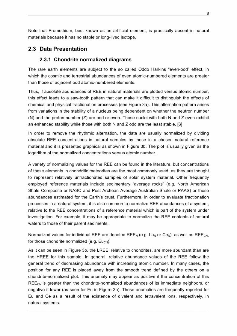
2.3 Data Presentation
2.3.1 Chondrite normalized diagrams
The rare earth elements are subject to the so called Oddo Harkins “even-odd” effect, in
which the cosmic and terrestrial abundances of even atomic-numbered elements are greater
than those of adjacent odd atomic-numbered elements.
Thus, if absolute abundances of REE in natural materials are plotted versus atomic number,
this effect leads to a saw-tooth pattern that can make it difficult to distinguish the effects of
chemical and physical fractionation processes (see Figure 3a). This alternation pattern arises
from variations in the stability of a nucleus being dependent on whether the neutron number
(N) and the proton number (Z) are odd or even. Those nuclei with both N and Z even exhibit
an enhanced stability while those with both N and Z odd are the least stable. [6]
In order to remove the rhythmic alternation, the data are usually normalized by dividing
absolute REE concentrations in natural samples by those in a chosen natural reference
material and it is presented graphical as shown in Figure 3b. The plot is usually given as the
logarithm of the normalized concentrations versus atomic number.
A variety of normalizing values for the REE can be found in the literature, but concentrations
of these elements in chondritic meteorites are the most commonly used, as they are thought
to represent relatively unfractionated samples of solar system material. Other frequently
employed reference materials include sedimentary “average rocks” (e.g. North American
Shale Composite or NASC and Post Archean Average Australian Shale or PAAS) or those
abundances estimated for the Earth’s crust. Furthermore, in order to evaluate fractionation
processes in a natural system, it is also common to normalize REE abundances of a system,
relative to the REE concentrations of a reference material which is part of the system under
investigation. For example, it may be appropriate to normalize the REE contents of natural
waters to those of their parent sediments.
Normalized values for individual REE are denoted REEN (e.g. LaN or CeN), as well as REECN,
for those chondrite normalized (e.g. EuCN).
As it can be seen in Figure 3b, the LREE, relative to chondrites, are more abundant than are
the HREE for this sample. In general, relative abundance values of the REE follow the
general trend of decreasing abundance with increasing atomic number. In many cases, the
position for any REE is placed away from the smooth trend defined by the others on a
chondrite-normalized plot. This anomaly may appear as positive if the concentration of this
REECN is greater than the chondrite-normalized abundances of its immediate neighbors, or
negative if lower (as seen for Eu in Figure 3b). These anomalies are frequently reported for
Eu and Ce as a result of the existence of divalent and tetravalent ions, respectively, in
natural systems.
Page 15
9
___________________________________________________________________________________________________________________________________________________________________________________________________________
(a) Actual abundances of the REE in a Certified Reference Material, OU-1 (Penrhyn Slate)
[9], and in ordinary chondrites by Wasson and Kallemeyn (1988). (b) Chondrite-normalized
abundances of the REE in NASC. The values plotted in (a) were used to construct this
graphic.
Unfortunately, there is a considerable variation in the reported REE concentrations of
chondritic meteorites, which has lead to a wide variety of normalizing values in the literature
[10]. Thus far, the adoption of only one agreed set of chondrite-normalizing concentrations
has not occurred. Table 2 shows some commonly used REE concentration values for
preparing chondrite-normalized plots.
Figure 3. Graphical representation of the rare earth elements in natural samples.
Page 16
10
___________________________________________________________________________________________________________________________________________________________________________________________________________
Table 2. The REE composition of commonly used chondritic meteorites.
Chondrites
Wakita et
al.
(1971)a
Masuda
et al.
(1973)a
Nakamura
(1974)a
Evensen
et al.
(1978)a
Boynton
(1984)a
Wasson &
Kallemeyn
(1988)b
McDonough
& Sun
(1995)a
REE Concentration values in µg/g (ppm)
La 0.34 0.378 0.329 0.2446 0.310 0.236 0.237
Ce 0.91 0.976 0.865 0.6379 0.808 0.616 0.613
Pr 0.121 - - 0.09637 0.122 0.0929 0.0928
Nd 0.64 0.716 0.630 0.4738 0.600 0.457 0.457
Sm 0.195 0.230 0.203 0.1540 0.195 0.149 0.148
Eu 0.073 0.0866 0.0770 0.05802 0.0735 0.056 0.0563
Gd 0.26 0.311 0.276 0.2043 0.259 0.197 0.199
Tb 0.047 - - 0.03745 0.0474 0.0355 0.0361
Dy 0.30 0.390 0.343 0.2541 0.322 0.245 0.246
Ho 0.078 - - 0.05670 0.0718 0.0547 0.0546
Er 0.20 0.255 0.225 0.1660 0.210 0.160 0.160
Tm 0.032 - - 0.02561 0.0324 0.0247 0.0247
Yb 0.22 0.249 0.220 0.1651 0.209 0.159 0.161
Lu 0.034 0.0387 0.0339 0.02539 0.0322 0.0245 0.0246
aData from Korotev (2009) [10] bWasson and Kallemeyn (1988) [11]
Page 17
11
___________________________________________________________________________________________________________________________________________________________________________________________________________
2.4 Importance of the Rare Earth Elements
The rare earth elements have become important from both scientific and technological points
of view.
The scientific significance of the REE relies on the realization that their behavior and
observed degree of fractionation in a rock or mineral can be essential for understanding
geochemical and petrogenetic processes.
The application of REE abundances to petrogenetic problems has centered on the study of
their distribution patterns and the radioactive decay scheme of some of their isotopes. The
first helps to evaluate the nature and source of rocks and minerals; since the REE
mobilization during processes of magma and rock formation can be predicted regarding their
geochemical properties (ionic radius, ionic charge and nature of bonding in geologic
systems) [6]. The second provides a tool to determine the ages of rocks and minerals.
Components of this approach are the decays of 138La to 138Ce, 147Sm to 143Nd, and 176Lu to 176Hf (atomic number 72) [1].
Their importance have additionally grown due to the current use of analytical methods which
are capable to generate wide data sets on several trace elements at a short time, and hence
allow geochemist to consider the REE abundances when performing petrogenetic studies,
even when the elements occur at very low concentrations.
Furthermore, the REE are of economic interest because the REE have many important
conventional and high-technology applications. Mixtures of the REE have traditionally been
used in catalysis (petroleum cracking, catalytic converters), ceramics, alloys, glass polishing
and coloring compounds. However, individual REE are increasingly being used in high-
technology applications such as high-strength permanent magnets (used in automobiles,
computers, etc.), cathode-ray tubes, fiber-optic cables, refrigeration and rechargeable
batteries. [12]
Page 18
12
___________________________________________________________________________________________________________________________________________________________________________________________________________
3 Analytical Procedure Developments in analytical chemistry have facilitated the routine determination of individual
REE in several geological materials, even when these are present at very low concentrations
and despite the fact that they have very similar chemical properties.
The most important analytical methods applied so far include: neuron activation analysis
(NAA), inductively coupled plasma atomic emission spectrometry (ICP-AES), inductively
coupled plasma mass spectrometry (ICP-MS), isotope dilution mass spectrometry (IDMS)
high performance liquid chromatography (HPLC) and ion chromatography (HPIC), and to a
minor extent X-ray fluorescence spectrometry (XRF). Each of them has its advantages,
disadvantages and limitations, with regard to its ability to determine the individual REE
effectively, instrumental detection limits and the difficulties of operation and sample
preparation.
Both variants of NAA: instrumental activation analysis, INAA, as well as radiochemical
activation analysis, RNAA, offer high sensitivity and are capable of the simultaneous
determination of many trace elements even at part per billion (ppb) levels. NAA has the
advantage of being a non destructive technique. The fact that the sample does not have to
be put into solution provides relative freedom from analytical blanks. However, difficulties
may be encountered in the determination of Pr, Er, Dy, Gd and Ho, due to the weak emission
of gamma rays or the unsuitable half-life of their isotopes. Main drawbacks of NAA are the
high cost (requires access to a nuclear reactor and long cooling times prior to the
determination) and safety requirements to handle radioactive materials. [6] [13] [14]
The ICP-AES and ICP-MS techniques have shown significant contribution in the
determination of REE in geological materials with very good specificity, precision and
accuracy, high sensitivity and wide dynamic range. On the other hand, spectrometric
determinations of REE in geological matrices are characterized by several limitations such as
high instrumental detection limits relative to the low REE concentration in most samples; and
high levels of chemical or spectral interferences, as a result of high concentrations of matrix
elements (e.g. Al, Ba, Ca Fe, Mg, Mn, Na, etc.) and other minor trace elements.
Consequently, the determination of REE by ICP-AES requires prior separation of these
elements from the matrix and their preconcentration for accurate results. ICP-MS has lower
detection limits and the spectra obtained are fairly simple, with far less spectral interference
than those in ICP-AES. For that reason, most of the REE can be directly determined in a
wide range of rocks types. However, significant isobaric, background and matrix induced
interferences do arise and must be taken into account. [15]
Isotope dilution mass spectrometry is a method of proven high accuracy, for which the
sources of systematic error are normally understood and controlled. For this reason, IDMS is
internationally accepted as a definitive method [16]. Nevertheless, there is also a small
possibility for analysis of REE without previous separation and concentration by this
technique, due to the detectability of the analytes and unwanted matrix effects.
Page 19
13
___________________________________________________________________________________________________________________________________________________________________________________________________________
The separation of individual members of the REE group employing both, HPLC and HPIC,
techniques have proved to be satisfactory, and have also been applied for their quantification
using online detection systems (i.e. UV–Vis, ICP-AES and ICP-MS). The selectivity, low
amount of sample needed and simultaneous analysis of several elements in a relative short
time are some advantages of these techniques. However, chemical dissolution of the sample
is required, as well as the previous separation of REE from most of the major rock
components to prevent overloading and precipitation of interfering elements in the column [4]
[17].
The present work is based on the application of an on-line HPIC/ICP-MS coupling system as
suitable method for the determination of REE in geological samples. In order to provide a
better understanding of this approach, the following sections present the necessary steps
prior separation and quantification by HPIC/ICP-MS (i.e. decomposition and preconcentration
of samples); as well as the important features of both, HPIC and ICP-MS, techniques
concerning their use on the determination of REE.
3.1 Sample Preparation
The rock or mineral must be placed in solution prior to analysis by HPIC and ICP-MS. This
pre-treatment should be followed by a REE group separation or matrix simplification
technique to remove matrix elements that coelute with the REE during chromatographic
separation and cause interferences in the REE determination.
3.1.1 Sample Decomposition Procedures
The complete dissolution of geological samples has proven to be difficult due to the presence
of resistant accessory minerals (e.g. garnet and zircon). The choice of the decomposition
method mainly depends upon the mineralogical characteristics of the rock sample, the nature
of the elements to be determined, precision and accuracy requirements, technical capability
of personnel, time constraints, and the instrument used for estimation. [18]
Balaram et al. (1995) compare three different decomposition methods (i.e. open acid
digestion, closed vessel digestion and fusion dissolution method) for the determination of
REE in anorthosites and other rock samples by ICP-MS. These three methods showed
comparable accuracies. Additionally, precisions better than 6%RSD were obtained for most
elements measured [18] . The procedures description and observations are summarized
below.
The open acid digestion, was performed mixing the sample with a mixture of HF, HNO3 and
HClO4 in an open system (i.e. PTFE beakers), and kept overnight for digestion, followed by
evaporation of the mixture to almost dryness at the next day. The constant addition of acid
mixture during the evaporation step at 200 °C was necessary to achieve a satisfactory
recovery of elements such a Cr, Ni, Zr, Ta, and Nd. It was reported, that sometimes elements
Page 20
14
___________________________________________________________________________________________________________________________________________________________________________________________________________
such as Fe, Pb, etc. were picked up from the environment during sample preparation, and
hence high procedure blank values were obtained by this method.
In the closed vessel digestion, the sample was mixed with an acid mixture containing HNO3,
HF and HCl (3:6:1) in a PTFE pressure decomposition vessel. After sealing the vessel, this
was placed in an electric oven at 110°C for 12 h. This procedure yielded very low blank
values and was found very effective for samples having high chromium content.
For fusion dissolution, the sample was mixed with lithium metaborate in a graphite crucible
and fused at 1000 °C for 5 min. After cooling, the melt was completely dissolved with an
HNO3 acid solution. The fusion results were very good for elements such as Cr, Zr, Hf and
showed a very good agreement with the certified values. This procedure showed high blank
values, and it was observed the loss of some volatile elements (e.g. Zn, Cs) due to the high
fusion temperature. Furthermore, the associated increase in the total dissolved solids caused
a reduction of the signal when measuring by ICP-MS.
As mentioned above, the results obtained by the three procedures were in agreement with
certified values. The methods based on fusion or sintering pose a good option when
choosing an adequate decomposition procedure, due to the fact that the REE are often
associated with high chemical resistant minerals, such as garnet and zircon. The complete
decomposition of these two minerals is necessary, because they strongly fractionate Sm
from Nd, and Lu from Hf [19]. In that matter, the use of Na2O2 or Na2CO3sintering has been
found to be one of the best ways of achieving complete dissolution in the determination of
REE by ICP-MS [15] [18] [20]. However, these techniques add high amount of salt to the
sample solution, which lowers the sensitivity of analytical techniques (i.e. ICP-MS), due to
the salt deposition on the cones and their subsequent clogging.
Microwave digestion has been also employed in the acid dissolution of geological samples
and it poses an option for sample preparation. [21] [22] [23]
3.2 Pre-concentration and Group Separation of Rare Earth Elements
The concentration of the REE in geological samples is typically low in comparison with the
high abundance of other elements present in the matrix solution. For these reasons, matrix
separation procedures and pre-concentration techniques including coprecipitation [24],
solvent extraction [25] and ion exchange using cation [26] and anion [27] exchange resins
have been used prior to analysis of sample solutions.
Among all the available techniques, ion exchange chromatography affords a simple
separation method if determinations are to be made by ICP-AES, ICP-MS, mass
spectrometry by isotope dilution, or neutron activation using a radiochemical separation. [5].
The principles and practical application of this technique to the separation of REE are
highlighted in the following section.
Page 21
15
___________________________________________________________________________________________________________________________________________________________________________________________________________
3.2.1 Ion exchange chromatography
Exchange chromatography refers to the reversible exchange of species between a solid
phase and a mobile phase. In the individual case of ion exchange, the species to be
exchanged are ions. The resin that serves as solid or “stationary” phase is normally packed
into a suitable glass tube, the “column”, and the sample solution poured onto the top of this
column. The sample is then “eluted” by washing its components through the column using a
suitable solvent. The species are separated one from another due to differences in their
affinity towards the resin. The higher the affinity, the larger the volume of eluent required to
wash it out of the exchange column [5]. Figure 4 illustrates the idealized exchange procedure
when separating two different analytes.
Figure 4. Ion exchange separation technique. (a) A solution containing two different species
is loaded onto the column. (b) The sample is eluted with the first aliquot of eluent and
separated in two fractions. (c) After the first analyte has been completely eluted, the second
analyte is desorbed from the resin with the second aliquot of solvent until complete elution is
achieved (d)
Ion exchange separation procedures, cation as well as anion exchange, have been used in
the determination of rare earth elements for the following reasons:
i) To concentrate the rare earth elements from a large to a small sample volume to allow
a concentration level above the determination limit of the analytical technique used for
their quantification.
ii) To remove matrix elements which cause interferences in the determination and
preclude a reliable analysis.
Page 22
16
___________________________________________________________________________________________________________________________________________________________________________________________________________
iii) To reduce the total dissolved solid content in solutions prepared by fusion or sintering
techniques.
3.2.1.1 Separation of REE by cation exchange
Cation exchange has been widely used for the group separation of REE. Commonly used
strong cation exchange resins include Dowex AG 50W-X8 (200-400 mesh) [28], Dowex AG
50W-X12 [29], Bio Rad AG 50-X8 (100-200 mesh) [5], Ostion LGKS 0800, sulfonated
polystyrene and bonded-phase silica. [17]
This separation technique makes use of three factors in achieving selectivity: the differences
in oxidation state; the radius of the trivalent REE ions; and the formation constants for
complexes formed between REE ions and additives in the mobile or stationary phase.
The technique involves the separation of the rare earth elements as a group. The strong
affinity of the free hydrated REE ions allows them to remain strongly bound to the resin while
other species (including transition metals, and alkali and alkaline earth elements) are washed
through the column and separated. The hydronium ion (H3O+) competes strongly for the
chelating sites on the resin and hence mineral acids are effective eluents.
The cation exchange separation of REE has been carried out in glass columns containing
varied amounts of resin slurry and using mostly hydrochloric acid and/or nitric acid solutions
as eluents. In general, the separation procedure follows the scheme described below:
i) The resin is preconditioned by passing certain amount of HCl or HNO3 acid solution,
ii) The sample solution is loaded onto the column.
iii) The sample is eluted using gradient elution technique.
iv) The column is washed for re-use by eluting HCl or HNO3 solutions.
A gradient elution technique refers to the use of successive aliquots of eluents. Typically the
concentration or acid strength (for acids) of the eluent is increased with every aliquot, in
order to decrease the affinity of the analytes for the resin and promote their desorption. In
this regard, the trivalent REE ions show high affinity for cation exchangers and cannot be
eluted from the stationary phase in the absence of relative high concentrated acid solutions
(e.g. 3-6 mol l-1 HCl and 2-8 mol l-1 HNO3) or adequate complexing agents. [17]
A comparison study of the separation of REE using nitric and hydrochloric acid as eluents is
presented in Potts (1992). The same cation exchange resin, Bio Rad AG 50-X8 100-200
mesh, is used in both separation tests. Here it is found that the elution using nitric acid
eliminates effectively Al, Ba, Be, Ca, K, Mg, Mn, Na, Sr, Ti, U, V; but, a large quantity of Fe
and some Zr remain in the REE fraction. On the other hand, by using the hydrochloric acid
elution, the complete elution of Al, Be, Fe, K, Mg, Mn, Na, Ti, U, V is achieved; however,
significant concentrations of Ca, Sr, Zr, and all Ba are carried over in the REE fraction. Such
Page 23
17
___________________________________________________________________________________________________________________________________________________________________________________________________________
observations should be taken into account when choosing an adequate separation
procedure.
The main drawbacks concerning the separation of rare earth elements by cation exchange
are the long time required for the percolation of the gravity-operated columns and the large
volume required to elute all the analytes of concern. Most chromatographic columns are 10-
20 cm length and 1-2 cm i.d., filled with ~20 g cationic resin (100-200 or 200-400 mesh).
Here the eluents flow at approximately 1 ml min-1, and complete separation is only achieved
after several hours of work. In addition, the use of such large volume of eluents may cause a
contamination blank, which impedes the accurate determination of the rare earth elements.
This has led to the development of ion exchange micro-columns and complex
chromatographic systems. [30] [31]
3.2.1.2 Separation of REE by anion exchange
Separation of rare earth elements by anion exchange chromatography have been mostly
performed using commercially available strong anion exchange resins, such a Dowex 1-X8
[32], Dowex 2-X8 (200-400 mesh) [33], Dowex 1-X4 [34], MCI GEL CA (08S, 08B, 06Y) and
Amberlite CG 400 (200-400 mesh) [17]; and mixed solvent elution (e.g. nitric acid-glacial
acetic acid, nitric acid-methanol) [17].
The separation is accomplished because negatively charged REE ions are formed when
dissolved in nitric acid mixtures containing excess methanol or glaciar acetic acid
(presumably REE-methoxy, REE(OCH3)x(x-3); and REE-acetate, REE(OOCCH3)x
(x-3),
respectively). This technique has been used not only with the aim to remove matrix elements
which seem to show no anion exchange (i.e. Al, Fe, K, Mg, Mn, Na and Sc), but also to split
the rare earth elements into fractions. [5] [17]
Anion exchange has not been as popular as cation exchange for REE separation due to the
poor column performance and low REE recoveries. It has been mostly applied in the
determination of rare earth elements by isotope dilution.
3.3 High Performance Liquid and Ion Chromatography
Of all the separation techniques such as chromatography, coprecipitation and liquid-liquid
extraction, only high performance liquid chromatography (HPLC) and ion chromatography
(HPIC) are capable of separating individual rare earths elements.
The separation of different species by HPLC and HPIC is based on the same
chromatographic principles explained in the previous section, with the difference that here
the analytes interact between a stationary and mobile phases in a high-pressure system.
This allows shorter time of analysis, the use of packing material with smaller particle size and
the consequent high degree of resolution.
Page 24
18
___________________________________________________________________________________________________________________________________________________________________________________________________________
Both HPLC and HPIC techniques have been also applied for the quantification of REE using
online detector systems.
3.3.1 Instrumentation
The HPLC or HPIC system basically consists of five main parts:
i) a mobile-phase supply system,
ii) a sample injection system,
iii) a separation system,
iv) a detection system, and
v) an interface and data processing system.
The basic set-up of a HPLC or HPIC contains a simple isocratic mobile-phase system (i.e.
only one eluent is introduced to the system). The use of two or more eluents is possible
when two or more pumps are involved in the mobile-phase supply system for mixing the
eluents (see Figure 5). In this case, the delivery system can be operated in a gradient elution
mode (i.e. the composition of the mobile phase could vary continuously).
The sample is injected into the analytical column either manually, using a syringe, or
automatically, using an electro-pneumatic valve with a sample loop or an autosampler.
The separation process takes place on the chromatographic column according to the HPLC
or HPIC mechanism. In both cases, the mobile phase (degasified eluent) flows through the
analytical column which acts as a carrier for the sample solution. High performance ion
chromatography is a form of liquid chromatography. The difference between HPLC and HPIC
is the packing material of the column. In contrast to HPLC, where a hydrophobic ion present
in the eluent (known as column modifier) is adsorbed onto the surface of a hydrophobic resin
to provide a charged surface for the ion exchange separation, high performance ion
chromatography uses conventional ion exchange columns whereby functional groups on the
resin exchange with the ions of interest. [35]
The detection system could contain one or more on-line detectors. The detector should be
able to monitor column effluents and provide a stable base line, low noise-level, high
sensitivity, high reproducibility and response to all analytes of interest. Commonly used on-
line detectors for REE determination include UV-Vis spectrometers, ICP-AES and ICP-MS.
[4]
For the UV-Vis detection method, the mobile phase and the REE are introduced into a post-
column reaction module after leaving the analytical column. There they are mixed with an
appropriately post-column reagent and the rare earth elements are then detected by
measuring the absorbance of the complex formed with the post-column reagent [36].
Arsenaso III and 4-(2-pyridylazo)-resorcinol monosodium salt (PAR) have been the most
Page 25
19
___________________________________________________________________________________________________________________________________________________________________________________________________________
widely used post-column reagents. In both cases, the REE are detected photometrically as
color complexes, at a wavelength of 650 nm and 520 nm respectively.
Figure 5. Schematic diagram of a typical HPLC or HPIC set-up with two eluents.
By detection chromatographic peaks with ICP-MS, it is possible to determine much lower
concentrations than with photometric detection. ICP-MS currently represents the most
sensitive detector and it is especially suited for on-line coupling of liquid chromatographic
methods, since the liquid that elutes from the HPLC or HPIC system can be directly
introduced into the torch of the ICP-MS.
The detector system is connected to a personal computer equipped with specialized
chromatographic software. The software provides chromatographic information such as
retention times, and peak height or peak areas.
Page 26
20
___________________________________________________________________________________________________________________________________________________________________________________________________________
3.3.2 Stationary and Mobile Phases
The aim of the chromatographic technique is to achieve the best possible separation, for
which all the single chromatographic conditions should be optimized.
The rare earth elements cannot be separated easily from each other as trivalent cations by
conventional cation exchange because their ionic properties are too similar. However, it has
been shown that certain organic chelating agents, contained in the mobile phase, can
replace part of the REE water hydration, forming complexes that enable ready separation of
the individual REE by conventional cation or anion exchange processes.
Verma et al. (2007) have published a complete review covering important developments on
HPLC and HPIC techniques for the determination of REE. The two LC methodologies mostly
used for REE determination are:
i) reversed-phase high performance liquid chromatography (RP-HPLC) using a C-18
column type and hydroxyisobutyric acid (HIBA) as mobile phase [37] [38] [39]. Rare
earth elements form singly positive charged complexes with HIBA that lower the affinity
of the lanthanide for the resin. The degree of complexation increases with increasing
atomic number, thus the REE which form the most stable complexes with HIBA, such
Lu, will elute first. Lanthanides such as La, which forms a weaker complex with HIBA,
elute later.
The complete separation of the 14 REE in synthetic standards using this separation
methodology has been reported. The separation was achieved in less than 15 min
using a gradient elution of HIBA. [40]
ii) HPIC using a IonPac CS5 column and a complex mixture of pyridine-2,6-dicarboxilic
acid (PDCA), oxalic acid and diglycolic acid as mobile phase. The use of stronger
complexing agents, such as oxalic acid, results in the formation of anionic REE-
complexes. Under these conditions, the REE can be separated by anion exchange.
PDCA is used as eluent chelator when transition metals (e.g. Fe) are present. The
transition metals form stable monovalent or divalent anionic complexes with PDCA,
while the rare earth elements form stable trivalent anionic complexes with it. The
resulting ionic charge differences permit the separation of REE from transition metals
prior separation of individual rare earth elements.
By using this scheme, the separation of 12 REE in a wide variety of rock types has
been reported. Here, the separation was achieved in less than 20 min. [35].
The two mentioned separation methodologies are by no means the only available separation
techniques for the determination of rare earth elements. They are however, the most widely
study and represent the currently the most efficient separation schemes.
Page 27
21
___________________________________________________________________________________________________________________________________________________________________________________________________________
3.4 Inductively Coupled Plasma Mass Spectrometry
Inductively Coupled Plasma Mass Spectrometry (ICP-MS) is an analytical technique for the
determination of trace, minor and major elements. This technique allows the measurement of
a wide range of elements in a single multi-element acquisition; it accepts almost any sample
type and also provides isotopic information. Due to these reasons, it has been widely
accepted as a useful tool by researchers, including those involved in geological matters. [15]
A commercial ICP-MS instrument consists of the following main components:
i) a sample introduction system,
ii) a plasma torch,
iii) an interface/vacuum system, and
iv) a mass analyzer and detector
In the typical configuration, ICP-MS implies the combination of an argon plasma source with
a quadrupole mass analyzer. Figure 6 illustrates the distinct parts of a typical ICP-MS. The
mode of operation and function of each part are outlined in the following section.
Figure 6. Schematic diagram of an Agilent 7500 Series ICP-MS instrument. Agilent
Technologies (2005).
Page 28
22
___________________________________________________________________________________________________________________________________________________________________________________________________________
3.4.1 Fundamentals of ICP-MS
The sample is typically introduced into the ICP-MS in liquid form by pumping it into the
sample introduction system, which consist of a nebulizer and spray chamber. It emerges as a
fine aerosol (with particles less than 10 μm diameter), which is eventually swept into the
central channel of the argon plasma.
The plasma source operates at very high temperature. It is generated in a stream of argon
contained in a quartz tube or “torch”. The torch is located in the center of a cooled copper coil
and operates at atmospheric pressure.
As the aerosol droplets travel through the different heating zones of the plasma torch, they
are dried, vaporized, atomized, and ionized. During this time, the sample is transformed from
liquid aerosol into a gas. When it finally arrives at the analytical zone of the plasma, at
approximately 7500K, it exists as positively charged ions.
The ions produced in the plasma are extracted into the vacuum system through the interface
consisting of two metal plates or “cones” (sample and skimmer cones) with small central
orifices. The ions are separated from the photons and residual neutral material by means of
electrostatic lenses as they pass through the vacuum system.
Finally, the positively charge ions reach the chamber where the mass spectrometer (MS) and
detector are housed. There, the quadrupole mass analyzer separates the ions according to
their mass to charge ratio (m/z). Taking into account that the plasma produces almost
exclusively single-charged ions, the m/z is equal to the mass of the ion. The electron
multiplier detects, counts and stores the total signal for each mass (m/z), and creates a fairly
simple mass spectrum.
The produced spectrum provides a simple representation of the sample, where the position
of the peak in the spectrum refers to the nature of the element (isotope) and the height of the
peak corresponds to its concentration. Thus, quantitative analysis is possible by comparing
the mass peaks to those generated by calibration standards under equal experimental
conditions. [15] [41]
3.4.2 Analysis of REE
The isotopes of all the REE, from the mass range of 139 to 179 a.m.u., can be determined by
ICP-MS. The combination of high sensitivity with the relatively simple spectra has made ICP-
MS more attractive than other techniques for the determination of these elements in rock
samples. For that reason, several studies on the determination of REE in geological samples
by ICP-MS have been published. [20] [21] [23] [42]
Page 29
23
___________________________________________________________________________________________________________________________________________________________________________________________________________
3.4.2.1 Spectral interferences
Spectroscopy interferences are probably the most significant class of interferences in ICP-
MS. They are caused by atomic or molecular ions that have the same mass to charge ratio
(m/z) as the analytes of interest. Such interferences are mainly caused by polyatomic ions
that are formed from precursors having numerous sources, such as the sample matrix,
reagents used for preparation, plasma gases, and entrained atmospheric gases. [43]
The main drawbacks associated with the determination of REE by ICP-MS arise from the
spectral interference of the LREE with the HREE. The REE which are subject to oxygen may
easily form oxides (MO+) and hydroxides (MOH+). These species occur 16 a.m.u. or 16+1
a.m.u above the parent ion and present a potential analytical problem for LREE since they
overlap with some of the low abundance HREE. [44]
Furthermore, the neighbor element barium (normally present at higher concentrations than
REE in nature) can form polyatomic ions BaO+ and BaOH+ which interfere with the analysis
of some REE. Table 3 shows potential spectroscopic interferences reported in the literature
for the determination of REE by ICP-MS. [43] [45]
To overcome spectral interferences, a number of measures including algebraic correction
[28], internal standardization [21], isotope-dilution [16], the standard addition method, the
application of matrix matching reference materials for calibration, among others, are
employed to obtain accurate REE data when precision is aimed.
The algebraic correction scheme is one approach to correct for the oxide and hydroxide
overlap interference. The major advantage is the simplicity of its application, possible without
any additional laboratory work. However, the mathematical correction to avoid the
interference of barium on europium is prone to large errors, due to the low stability of barium
oxide, and negative results are sometimes obtained when the ratio of Ba/Eu is high [28] [46].
Considering the last, the separation of Ba from the analyte system prior REE determination
by ICP-MS would be of great significance, especially due to the polyatomic interferences on
Eu, which is important to describe the REE pattern in most geological materials (Eu
anomaly).
Page 30
24
___________________________________________________________________________________________________________________________________________________________________________________________________________
Table 3. Possible spectroscopic interferences on the REE in their determination by ICP-MS
Lanthanide Mass Abundance Interference
La 139 99,9 123TeO, 123SbO
Ce 140 88,5 124TeO, 124SbO
Pr 141 100 125TeO
Nd 146 17,2 98Ru16O3, 130Ba16O
150 5,64 102Ru16O3, 134Ba16O, 150Sm
Sm 147 15,0 99Ru16O3, 130Ba16OH
152 26,7 104Ru16O3, 136Ba16O, 136Ce16O, 135Ba16OH, 152Gd
154 22,7 138Ba16O, 138La16O, 138Ce16O, 137Ba16OH, 154Gd
Eu 151 47,8 135Ba16O, 134Ba16OH
153 52,2 137Ba16O, 136Ba16OH
Gd 155 14,8 139La16O
156 20,5 140Ce16O, 139La16OH, 156Dy
157 15,7 138B19F, 141Pr16O+, 140Ce16OH
160 21,9 144Nd16O, 144Sm16O, 160Dy
Tb 159 100 143Nd16O, 142Ce16OH, 142Nd16OH
Dy 161 18,9 145Nd16O, 144Nd16OH, 144Sm16OH
162 25,5 146Nd16O, 145Nd16OH
163 24,9 147Sm16O+, 146Nd16OH
Ho 165 100 149Sm16O, 148Nd16OH, 148Sm16OH
Er 166 33,6 160Nd16O, 150Sm16O, 149Sm16OH
167 22,9 151Eu16O+, 150Nd16OH, 150Sm16OH
168 26,8 152Sm16O, 152Gd16O, 151Eu16OH
Tm 169 100 153Eu16O, 152Sm16OH, 152Gd16OH
Yb 171 14,3 155Gd16O, 154Sm16OH, 154Gd16OH
172 21,9 156Gd16O
173 16,1 157Gd16O
174 31,8 158Gd16O, 158Dy16O, 157Gd16OH, 174Hf
Lu 175 97,4 159Tb16O, 158Gd16OH
Page 31
25
___________________________________________________________________________________________________________________________________________________________________________________________________________
3.4.3 Coupling of ICP-MS to a chromatographic system
The combination of chromatographic techniques with ICP-MS represents currently a growing
area of study. This coupling system has been used in order to overcome the isobaric
interferences mentioned in the previous section. [31] [36] [47] [48] [49]
However, the varying compositions of the eluents used as mobile phase for the
chromatographic separation could influence the ionization efficiency in the plasma and the
exact external calibration of chromatograms, hindering therefore the quantitative
determination by ICP-MS.
Heumann et al. (1998) describe the on-line coupling of chromatographic methods with
inductively coupled plasma mass spectrometry, where a simultaneous isotope dilution step is
added for accurate quantification of chromatographic peaks. The advantage of applying the
isotope dilution technique is that the quantification by the ID analysis is based on the
measurement of isotope ratios and not on the absolute intensity of the ions. Thus, 100%
recoveries of REE are not essential as samples are spiked prior to separation, and so the
drawbacks of this on-line coupling are overcome. [16] [50]
It is expected that the technique of ID will be used in our laboratory more extensively
together with HPIC-ICP-MS systems due to the exceptional precision and accuracy of their
combined approach.
Page 32
26
___________________________________________________________________________________________________________________________________________________________________________________________________________
4 Experimental
4.1 Materials and Reagents
All reagents used in the preparation of samples were of analytical grade. Sodium peroxide
(purity 95%, Alfa Aesar), and HCl (fuming 37% v/v, sub-boiled) were used for sample
dissolution. The nitric acid solutions were prepared from concentrated HNO3 (65% v/v, sub-
boiled).
Rare earth elements standard solutions were prepared by diluting a multi-element ICP-MS
standard solution (Inorganic Ventures, Ontario, Canada) with 1 % v/v HNO3.Thulium
standard solutions were made by serial dilutions of 1000 μg ml-1 single element stock
solution (Inorganic Ventures, Ontario, Canada) in a final medium of 1 % v/v HNO3. All the
dissolutions were prepared using deionized water (18 MΩcm-1), purified by a Milli-Q Plus
ultrapure water system, Millipore Corporation.
Separation of the sample matrix was performed using Bio-Rad® borosilicate glass columns
filled with Dowex 50W-X8 cation exchange resin with a particle size between 200 and 400
mesh.
Oxalic acid and diglycolic acid were reagents of analytical grade. The solution of diglycolic
acid was pre-cleaned by passing it through a Dowex 50W-X8 cation exchange column, in
order to reduce the high background signal of this eluent. Both eluents were placed in
ultrasonic bath for degassing prior to use.
4.2 Instrumentation Individual REE were separated using a Dionex chromatographic system (Dionex
Corporation, Sunnyvale, California, U.S.A.) equipped with a Dionex GS50 gradient pump, an
IonPac® CG5A (2 x 50 mm) guard column and an IonPac® CS5A (2 x 250 mm) analytical
column.
Detection was by means of an Agilent 7500 Series ICP-MS (Agilent Technologies).
Chromatographic data were collected in a personal computer and analyzed using Agilent
7500 Series ICP-MS Plasma Chromatographic Software.
4.3 Geological Reference Materials
The determination of the REE concentrations in reference materials is used to monitor the
quality and accuracy of ICP-MS measurements in the present work [51]. The reference
materials BIR-1 (Icelandic Basalt) [52], and BRP-1 (Basalt Ribeirão Preto) [53] were chosen
to evaluate the effectiveness of the proposed analytical methodology due to their different
REE concentration range.
Page 33
27
___________________________________________________________________________________________________________________________________________________________________________________________________________
4.4 Samples
The rock samples OU-10 (Longmyndian greywacke, GeoPT24), OPC-1 (Portland Cement
GeoPT26), OKUM (Komatiitic Basalt) and MUH-1 (Harzburgite) were analyzed in different
steps of the proposed methodology (i.e. cation exchange separation, determination by
HPLC-ICP-MS and/or determination by HPLC-ICP-MS after Tm addition).
4.5 Sample Preparation
All the samples and reference materials analyzed in the present study were prepared using
the procedure indicated below.
About 100 mg of powdered sample material were weighted together with 0,6 g fine grained
Na2O2 in a carbon crucible. The crucibles were taken into a muffle furnace at 480 °C for 0,5 h
for sample sintering. After the crucibles were cooled, water was added carefully and the
resulting solution was centrifuged to separate the undissolved material. The supernatant was
collected in a volumetric flask and the solid material was dissolved using 3 ml HCl 3 mol l-1.
The crucibles were rinsed with 2 ml of concentrated HCl and the solution formed was added
to the volumetric flask together with the dissolved material and diluted to 100 ml with MilliQ
water [20].
4.6 Ion Exchange Chromatographic Group Separation
The cation exchange chromatography with a sulfonated polystyrene resin, Dowex 50W-X8
for the separation of rare earth elements from unwanted matrix elements was studied. The
resin was chosen because it is well known to provide an effective REE separation, and also
because the involved eluents are inorganic acids, which make the final solution suitable for
ICP-MS analysis.
Previous studies using the same resin show that after elution with increasing concentrations
of HCl, elements such as Ba, Ca, Sr and Zr remain in the REE-fraction [26] [5]. Using HNO3
as eluent, Ba, Ca and Sr are efficiently desorbed from the resin prior to the elution of REE,
but Fe and part of Zr are retained and elute together with the REE group [5]. Several studies
consider the use of both acid in a sequential elution to minimize the number of non-REE
constituents and their concentrations in the final solution [28] [54] [55] [56] [57] .
In the present work, two main separation schemes were studied in order to remove the
matrix elements from the samples and preconcentrate the rare earth elements: the
HNO3/HCl sequential elution and the separation using a nitric acid media. The main
characteristic of each separation scheme is explained later in this work.
At the beginning of the experiments, the resin slurry was placed in a borosilicate glass
column and converted in its H+ form by equilibration with an acid media. All the experiments
were carried out using the geochemical reference material BRP-1 as sample. The elution
Page 34
28
___________________________________________________________________________________________________________________________________________________________________________________________________________
profiles of Ba, Fe, and the REE were studied by collecting 5 ml (Ba and Fe fractions) and 2,5
ml (REE fraction) aliquots of the eluents from the beginning of the elution steps.
The collected fraction were diluted to 10 ml with water and analyzed by ICP-MS. Indium and
rhenium were used as internal standards. Geochemical reference samples of a similar matrix
were used for calibration. The ICP-MS operating parameters are shown in Table 4.
The use of a set of columns packed with 2-5 ml of resin was chosen to perform the
separation tests, instead of only one column filled with big amounts of the resin, in order to
reduce the elution time per sample (see Figure 7).
The optimization of the complete process was pursued by changing the diameter of the glass
columns, the amount of resin employed, the volume of the analyzed sample and the volume
of the involved eluents.
Table 4. ICP-MS operating parameters and conditions
ICP-MS instrument Agilent 7500 Series
Instrument power 1500 W
Nebulizer PFA microconcentric
Sample cone Nickel
Skimmer cone Nickel
Carrier gas flow rate 1 l min-1
Makeup gas flow rate 0,1 l min-1
Sample uptake rate approx. 0,2 ml min-1
Figure 7. Battery of columns filled with Dowex 50W-X8 used for the cation exchange
separation procedures.
Page 35
29
___________________________________________________________________________________________________________________________________________________________________________________________________________
4.6.1 HCl/HNO3 sequential elution
For these experiments, the cation exchange column was conditioned with 2 mol l-1 HCl.
Afterwards, the sample was loaded onto the resin column and Fe and other unwanted matrix
elements were eluted with 2 mol l-1 HCl. The column was rinsed with water to minimize the
concentration of HCl. Afterwards, Ba and other alkaline earth elements were eluted using 2
mol l-1 HNO3. Finally, the REE were eluted with 6 mol l-1 HNO3, followed by 8 mol l-1 HNO3.
Table 5 summarizes all the procedures performed following this scheme.
Table 5. HCl/HNO3 sequential elution procedures tested for separation and preconcentration
of rare earth elements
Chromatographic Separation Procedure 1 2 3 4
Column (length x diameter) 10 cm x 10 mm 10 cm x 10 mm 10 cm x 10 mm 10 cm x 10 mm
Amount of resin (ml) 3 5 5 5
Column equilibration
20 ml 2 mol l-1 HCl
20 ml 2 mol l-1 HCl
20 ml 2 mol l-1 HCl
20 ml 2 mol l-1 HCl containing 0,5 mol l-1
oxalic acid
Sample volume (ml) 5 5 5 5
1 40 ml 2 mol l-1
HCl 20 ml 2 mol l-1
HCl 15 ml 2 mol l-1
HCl
20 ml 2 mol l-1 HCl containing 0,5 mol l-1
oxalic acid
2 5 ml H2O 10 ml 4 mol l-1
HCl 10 ml H2O 10 ml H2O
3 40 ml 2 mol l-1
HNO3 10 ml H2O
15 ml 2 mol l-1 HNO3 containing 0,5 mol l-1 oxalic
acid
50 ml 2 mol l-1 HNO3
4 30 ml 6 mol l-1
HNO3 50 ml 2 mol l-1
HNO3 35 ml 2 mol l-1
HNO3 20 ml 6 mol l-1
HNO3
Elut
ion
Gra
dien
t
Step
5 -- 30 ml 6 mol l-1
HNO3 20 ml 8 mol l-1
HNO3 10 ml 8 mol l-1
HNO3
4.6.2 Nitric acid media
In this study, the cation exchange column was first conditioned with 2 mol l-1 HNO3 containing
oxalic acid. After the sample solution was passed through the column, Fe and other transition
metals were eluted using 2 mol l-1 HNO3 containing 0,5 mol l-1 or 0,7 mol l-1 oxalic acid.
Afterwards, 2 mol l-1 HNO3 was loaded onto the column, whereby the alkaline earth elements
are washed off prior to elution of the REE. The REE and Y are eluted using 6 mol l-1 HNO3
and 8 mol l-1 HNO3. Table 6 show details about the separation procedures that were
evaluated regarding this separation schemes.
Page 36
30
___________________________________________________________________________________________________________________________________________________________________________________________________________
Table 6. Nitric acid media procedures tested for separation and preconcentration of rare
earth elements 8
10
cm
x 1
0
mm
3
25
ml 2
mo
l l-1
HN
O3
con
tain
ing
0,5
mo
l l-1
oxa
lic a
cid
20
10
ml 2
mo
l l-1
HN
O3
con
tain
ing
0,5
mo
l l-1
oxa
lic a
cid
30
ml 2
mo
l l-1
HN
O3
20
ml 6
mo
l l-1
HN
O3
5 m
l 8 m
ol l
-1
HN
O3
7
10
cm
x 1
0
mm
3
25
ml 2
mo
l l-1
HN
O3
con
tain
ing
0,5
mo
l l-1
oxa
lic a
cid
10
10
ml 2
mo
l l-1
HN
O3
con
tain
ing
0,5
mo
l l-1
oxa
lic a
cid
30
ml 2
mo
l l-1
HN
O3
20
ml 6
mo
l l-1
HN
O3
10
ml 8
mo
l l-1
HN
O3
6
10
cm
x 1
0
mm
3
25
ml 2
mo
l l-1
HN
O3
con
tain
ing
0,5
mo
l l-1
oxa
lic a
cid
1
10
ml 2
mo
l l-1
HN
O3
con
tain
ing
0,5
mo
l l-1
oxa
lic a
cid
30
ml 2
mo
l l-1
HN
O3
20
ml 6
mo
l l-1
HN
O3
5 m
l 8 m
ol l
-1
HN
O3
5
10
cm
x 1
0
mm
3
25
ml 2
mo
l l-1
HN
O3
con
tain
ing
0,5
mo
l l-1
oxa
lic a
cid
1
10
ml 2
mo
l l-1
HN
O3
con
tain
ing
0,5
mo
l l-1
oxa
lic a
cid
30
ml 2
mo
l l-1
HN
O3
20
ml 6
mo
l l-1
HN
O3
10
ml 8
mo
l l-1
HN
O3
4
10
cm
x 1
0
mm
3
15
ml 2
mo
l l-1
HN
O3
con
tain
ing
0,7
mo
l l-1
oxa
lic a
cid
1
15
ml 2
mo
l l-1
HN
O3
con
tain
ing
0,7
mo
l l-1
oxa
lic a
cid
25
ml 2
mo
l l-1
HN
O3
20
ml 6
mo
l l-1
HN
O3
10
ml 8
mo
l l-1
HN
O3
3
10
cm
x 1
0
mm
3
15
ml 2
mo
l l-1
HN
O3
con
tain
ing
0,5
mo
l l-1
oxa
lic a
cid
1
15
ml 2
mo
l l-1
HN
O3
con
tain
ing
0,5
mo
l l-1
oxa
lic a
cid
25
ml 2
mo
l l-1
HN
O3
20
ml 6
mo
l l-1
HN
O3
10
ml 8
mo
l l-1
HN
O3
2
10
cm
x 1
0
mm
5
20
ml 2
mo
l l-1
HN
O3
con
tain
ing
0,7
mo
l l-1
oxa
lic a
cid
5
20
ml 2
mo
l l-1
HN
O3
con
tain
ing
0,7
mo
l l-1
oxa
lic a
cid
40
ml 2
mo
l l-1
HN
O3
20
ml 6
mo
l l-1
HN
O3
10
ml 8
mo
l l-1
HN
O3
Chr
omat
ogra
phic
Sep
arat
ion
Proc
edur
e
1
10
cm
x 1
0
mm
5
20
ml 2
mo
l l-1
HN
O3
con
tain
ing
0,5
mo
l l-1
oxa
lic a
cid
5
20
ml 2
mo
l l-1
HN
O3
con
tain
ing
0,5
mo
l l-1
oxa
lic a
cid
30
ml 2
mo
l l-1
HN
O3
30
ml 6
mo
l l-1
HN
O3
20
ml 8
mo
l l-1
HN
O3
1 2 3 4
Step
Col
umn
(le
ng
th
x d
iam
ete
r)
Am
ount
of
resi
n (m
l)
Col
umn
equi
libra
tion
Sam
ple
volu
me
(ml)
Elution gradient
Page 37
31
___________________________________________________________________________________________________________________________________________________________________________________________________________
Table 5. Nitric acid media procedures tested for separation and preconcentration of rare
earth elements (cont.) 16
10
cm
x 5
mm
2
15
ml 2
mo
l l-1
HN
O3
con
tain
ing
0,5
mo
l l-1
oxa
lic a
cid
10
10
ml 2
mo
l l-1
HN
O3
con
tain
ing
0,5
mo
l l-1
oxa
lic a
cid
15
ml 2
mo
l l-1
HN
O3
15
ml 6
mo
l l-1
HN
O3
5 m
l 8 m
ol l
-1
HN
O3
15
10
cm
x 5
mm
2
15
ml 2
mo
l l-1
HN
O3
con
tain
ing
0,5
mo
l l-1
oxa
lic a
cid
5
10
ml 2
mo
l l-1
HN
O3
con
tain
ing
0,5
mo
l l-1
oxa
lic a
cid
15
ml 2
mo
l l-1
HN
O3
15
ml 6
mo
l l-1
HN
O3
5 m
l 8 m
ol l
-1
HN
O3
14
10
cm
x 5
mm
2
15
ml 2
mo
l l-1
HN
O3
con
tain
ing
0,5
mo
l l-1
oxa
lic a
cid
5
15
ml 2
mo
l l-1
HN
O3
con
tain
ing
0,5
mo
l l-1
oxa
lic a
cid
15
ml 2
mo
l l-1
HN
O3
20
ml 6
mo
l l-1
HN
O3
5 m
l 8 m
ol l
-1
HN
O3
13
10
cm
x 5
mm
2
15
ml 2
mo
l l-1
HN
O3
con
tain
ing
0,5
mo
l l-1
oxa
lic a
cid
1
12
,5 m
l 2 m
ol
l-1 H
NO
3
con
tain
ing
0,5
mo
l l-1
oxa
lic a
cid
15
ml 2
mo
l l-1
HN
O3
12
,5 m
l 6 m
ol
l-1 H
NO
3
5 m
l 8 m
ol l
-1
HN
O3
12
10
cm
x 5
mm
2
15
ml 2
mo
l l-1
HN
O3
con
tain
ing
0,5
mo
l l-1
oxa
lic a
cid
1
12
ml 2
mo
l l-1
HN
O3
con
tain
ing
0,5
mo
l l-1
oxa
lic a
cid
12
ml 2
mo
l l-1
HN
O3
10
ml 6
mo
l l-1
HN
O3
5 m
l 8 m
ol l
-1
HN
O3
11
10
cm
x 5
mm
2
15
ml 2
mo
l l-1
HN
O3
con
tain
ing
0,5
mo
l l-1
oxa
lic a
cid
1
15
ml 2
mo
l l-1
HN
O3
con
tain
ing
0,5
mo
l l-1
oxa
lic a
cid
20
ml 2
mo
l l-1
HN
O3
20
ml 6
mo
l l-1
HN
O3
10
ml 8
mo
l l-1
HN
O3
10
10
cm
x 1
0
mm
2
25
ml 2
mo
l l-1
HN
O3
con
tain
ing
0,5
mo
l l-1
oxa
lic a
cid
10
7 m
l 2 m
ol l
-1
HN
O3
con
tain
ing
0,5
mo
l l-1
oxa
lic a
cid
18
ml 2
mo
l l-1
HN
O3
20
ml 6
mo
l l-1
HN
O3
5 m
l 8 m
ol l
-1
HN
O3
Chr
omat
ogra
phic
Sep
arat
ion
Proc
edur
e
9
10
cm
x 1
0
mm
2
25
ml 2
mo
l l-1
HN
O3
con
tain
ing
0,5
mo
l l-
1o
xalic
aci
d
10
10
ml 2
mo
l l-1
HN
O3
con
tain
ing
0,5
mo
l l-1
oxa
lic a
cid
30
ml 2
mo
l l-1
HN
O3
20
ml 6
mo
l l-1
HN
O3
10
ml 8
mo
l l-1
HN
O3
1 2 3 4
Step
Col
umn
(le
ng
th x
dia
me
ter)
Am
ount
of
resi
n (m
l)
Col
umn
equi
libra
tion
Sam
ple
volu
me
(ml)
Elution gradient
Page 38
32
___________________________________________________________________________________________________________________________________________________________________________________________________________
4.6.3 Detection Limits
The determination of detection limits provides a useful mechanism for evaluating the
analytical method and its applicability compared to other methods. The detection limits are
matrix, instruments, method and analyte specific. For this reason, it is important to carefully
control the variables that may cause a detection limit to be high, such as blank
contamination. [58]
Two detection limits were determined in the present work using the procedural blanks
obtained during the sample preparation and matrix separation:
The Limit of Detection (LOD) is commonly defined as the lowest concentration level of an
analyte, which gives an instrumental signal significantly different from a blank or background
signal. It is given as the mean concentration of the blank measurements (xi) plus 3 times the
standard deviation (s) of a blank.
The limit of quantitation (LQD) or limit of determination is the lowest concentration at which
the analyte can be reliably detected. Quantitation is generally agreed to begin at a
concentration equal to 10 standard deviations of the blank. The LQD is determined then by
the equation LQD = xi + 10s. [58]
4.7 Separation and Determination of Individual Rare Earth Elements by HPLC-ICP-MS
The separation and determination of rare earth elements by a coupled HPIC-ICP-MS system
using a IonPac® CS5A exchange column, preceded by a smaller IonPac® CG5A guard
column has been studied.
The analytical column CS5A contains both cation and anion exchange sites, providing so a
heterogeneous system for the separation of the rare earth elements. Bruzzoniti et al. (1996)
explain the separation mechanism on the CS5A column at the presence of oxalic and
diglycolic acid by means of the high stability constants of this ligands with the REE, which
allows the formation of (REE)L33- species. Using oxalic acid as complexing agent, the LREE
are separated by anion exchange and eluted from the column, while the HREE remain fixed
as cations in the ion exchange sites of the resin. The use of diglycolic acid, a stronger ligand,
will assist the formation of HREE complexes and their subsequent separation by anion
exchange. [59]
The HPIC method developed in this study is based on the technique of Dionex (1991), which
describes the REE separation using the CS5A column and a mixture of oxalic acid, diglycolic
acid and deionized water as mobile phase [60]. However, several modifications were made
in order to optimize the separation and the detection with ICP-MS.
Figure 8 shows the basic chromatographic system used in all the optimization experiments.
Page 39
33
___________________________________________________________________________________________________________________________________________________________________________________________________________
Figure 8. Schematic HPIC system used for this work.
Figure 9. Post-column detection system. A two inlet device is used to mix the eluent flow with
a standard solution before nebulization into the ICP-MS to correct for drift in sensitivity.
From the column
To the spray chamber
Internal standard solution
Page 40
34
___________________________________________________________________________________________________________________________________________________________________________________________________________
Numerous experiments were conducted in order to find the best separation conditions for the
rare earth elements. A REE synthetic solution was used as sample to perform the
optimization tests. The sample solution was injected into a 50 μl sample loop and introduced
into the eluent stream via injection valve. Following separation, the eluent was mixed with a
50 ng ml-1 In and Re solution for internal standardization and directed to the ICP-MS spray
chamber for detection. The internal standard solution was pumped constantly into the
analytical stream via peristaltic pump at a rate of 0,1 ml min-1 (see Figure 9). The HPIC-ICP-
MS operating conditions are given in Table 7.
Table 7. Analytical conditions for the analysis of rare earth elements by HPIC-ICP-MS
HPIC: Guard column IonPac® CG5A
Analytcal column IonPac® CS5A
Eluent 1 Deionized water
Eluent 2 0,1 mol l-1 Oxalic acid, pH 4,8 Eluent 3 0,1 mol l-1 Diglycolic acid, pH 4,8
Flow rate 0,3 – 0,4 ml min-1
Sample loop volume 50 μl
ICP-MS Agilent 7500 Series
4.7.1 Separation procedure optimization
The optimization was basically performed for the mobile phase. The gradient program
described in Dionex TN23 (1991) was chosen as starting point for the optimization.
The modifications made to this method include the use of an ammonia solution for pH
adjustment, instead of lithium hydroxide which may cause problems in ICP-MS analysis due
to the salt loading. Another major modification was the elimination of the post column
reaction step, since it was found to be unnecessary when using ICP-MS as detector. Figure
10 shows the chromatogram obtained at the starting point of the optimization experiments.
Here the chromatographic peaks for Y, La, Ce, Pr, and Nd are plotted using a secondary y-
axis for better visualization.
The gradient was reset to the initial separation conditions and hold for 10 min between each
chromatographic run in order to equilibrate the column.
The optimization procedure focused on:
i) achieving complete separation of Yb from Lu,
ii) increasing the separation efficiency of the elements from La to Nd, and
Page 41
35
___________________________________________________________________________________________________________________________________________________________________________________________________________
iii) reducing the total time required for the separation and elution of all the REE.
4.7.2 Isobaric mass interferences
The chromatographic separation of REE prior determination by ICP-MS eliminates all
possible interfering overlaps, including those caused by isobaric (REE+) and polyatomic
(REEO+ and REEOH+) species, which affect the ICP-MS measurement. For example, CeO,
PrO and NdO are well separated from the corresponding Gd isotopes of 16 a.m.u. higher, as
can be observed in Figure 11.
Cerium isotope 142Ce is also well separated from 142Nd (see mass 142 in Figure 11). That
means that the concentration or isotope ratios can be measured directly on the
corresponding peaks without interferences from other rare earth elements.
Figure 10. Chromatogram of a REE synthetic sample solution obtained at the beginning of
the optimization process. The analytical conditions are listed in Table 7. The gradient
program was taken from Dionex (1991). The pH value of E2 and E3 was adjusted to 4,8 with
4 mol l-1 ammonia solution.
Page 42
36
___________________________________________________________________________________________________________________________________________________________________________________________________________
4.7.3 Method Standardization
Once the optimum conditions for cation exchange, as well as for HPIC separation, were
established, data on REE concentration in geological reference materials (BIR-1 and BRP-1)
and samples (OU-1, OPC-1 and OKUM) were obtained and compared with reference values
to assess the validation parameters of the proposed methodology.
4.7.4 Standard Addition
Experiments which consider the approach presented in Barrat, et al. (1996), were
additionally performed in order to overcome the errors introduced by sample losses during
the sample handling and chromatography, and to improve the quantification of the REE in
samples with low concentration levels of these elements.
The work from Barrat, et al. (1996) describes a method based in the addition of a known
amount of thulium (Tm) to the sample, which can be used in routine analysis of geological
samples. [61].
The Tm addition has been applied under the assumption that the positive Tm anomaly in the
REE pattern of a sample cause by the addition of a small amount of Tm can be used to
monitor the losses during the analytical process by comparing the measured concentration of
Figure 11. Chromatogram of Ce, Pr, Nd and Gd. The interferences from polyatomic and
isobaric species are overcome by the chromatographic separation. The masses 140, 141
and 142 are plotted using a secondary y-axis.
Page 43
37
___________________________________________________________________________________________________________________________________________________________________________________________________________
thulium in the sample with the concentration obtained by interpolation of the correspondent
Tm abundance using the Er and Yb abundances in chondrites. The principles of the
quantification of REE in a sample spiked with Tm were described in Barrat, et al. (1996) and
are presented below.
First, the thulium concentration of the sample with no spike contribution (CTm*) is calculated
by interpolation of the concentrations of erbium and ytterbium the sample solution, CEr and
CYb (in μg g-1), respectively; using the chondritic abundances as follows:
CTm* = 0,02561 ((CEr/0,166).(CYb/0,1651)1/2
The abundance of a rare earth element in a sample, [X] (in μg g-1), can be obtained
according to:
[X] = (MTm . Cx)/((M . (CTm - CTm*))
Where M is the mass of sample spiked with Tm (in g); MTm, the amount of Tm added (in g);
and Cx, the measured concentration for X (in μg g-1) in the sample solution.
This calculation is valid only if the HREE abundances of the sample follow a normal REE
pattern, which means the absence of Yb anomaly, feature that has been observed in some
extraterrestrial minerals.
Page 44
38
___________________________________________________________________________________________________________________________________________________________________________________________________________
5 Results and Discussion
5.1 Cation Exchange Separation Elution Curves
The percentage amounts of eluted elements were plotted versus the eluted volume. The
elution profiles of the REE, together with those of Fe and Ba for all the separation procedures
tested are shown in Appendix A-1. In each case gradient elutions were used (as indicated on
the diagrams).
The elution curves showed in this section were chosen to be representative of all the elution
patterns which achieved good separation results, and are used to compare all the factors
tested by the optimization of the cation exchange group separation of REE using a Dowex
50W-X8 resin.
The total time required for each separation procedure varied from 2 to 4 hours, depending on
the amount of resin, sample and eluents employed, and on the internal diameter of the
column. A reduction in the flow rate was always observed when a higher acid concentration
was used (i.e. 4 mol l-1 HCl, 6 mol l-1 and 8 mol l-1 HNO3), because of dehydration and
consequent compaction of the resin.
5.1.1 HCl/HNO3 sequential elution
The elution curves obtained for this separation scheme indicates that Fe and Ba are
completely washed off the column by elution with 2 mol l-1 HCl and 2 mol l-1 HNO3,
respectively.
Figure 12 shows the chromatographic separation of eight REE from Fe and Ba using
HCl/HNO3 sequential elution. On these conditions a large fraction of Fe elutes with the
addition of 15 ml of 2 mol l-1 HCl. Water is added to avoid mixing HCl and HNO3 which may
cause the increase in acid strength and the subsequent desorption of the REE from the
resin. The elution of Ba begins after the addition of the first 20 ml of 2 mol l-1 HNO3, finishing
this process after the total addition of 50 ml of 2 mol l-1 HNO3. Oxalic acid was added to the
first 15 ml of 2 mol l-1 HNO3 to assure complete elution of Fe. The REE elution starts when 8
mol l-1 HNO3 is added.
In order to decrease the volume of eluent needed to separate Fe, 2 mol l-1 HCl containing
oxalic acid was employed. As showed in Figure 13, Fe is completely removed with the first
15 ml of this eluent. On the other hand, 50 ml of 2 mol l-1 HNO3 are still needed to complete
barium elution. Effective desorption of REE with 6 mol l-1 HNO3 is achieved as well as with 8
mol l-1 HNO3. Therefore, the use of 6 mol l-1 HNO3 is preferred for the elution of REE,
because it represents a reduction in the amount of reagents needed.
Page 45
39
___________________________________________________________________________________________________________________________________________________________________________________________________________
Figure 13. Amount of eluted elements (%) vs. elution volume with 2 mol l-1 HCl containing 0,5
mol l-1 oxalic acid, followed by 2 mol l-1, 6 mol l-1 and 8 mol l-1 HNO3. Five milliliter of
sample solution were passed through a 10 cm length x 10 mm i.d. glass column
packed with 5 ml Dowex 50W-X8
Figure 12. Amount of eluted elements (%) vs. elution volume with 2 mol l-1 HCl, 2 mol l-1 HNO3
and 8 mol l-1 HNO3. Five milliliter of sample solution were passed through a 10 cm
length x 10 mm i.d. glass column packed with 5 ml Dowex 50W-X8
Page 46
40
___________________________________________________________________________________________________________________________________________________________________________________________________________
The volume of 2 mol l-1 HCl used to elute Fe has to be carefully chosen considering the
amount of resin and volume of sample employed. This is because the elution of larger
volumes of 2 mol l-1 HCl could cause the removal of small portions of the heavy rare earth
elements together with the Fe fraction. Due to the same reasons higher concentrations of
hydrochloric acid, as well as volumes of water lower than 10 ml, are not recommended (see
Appendix A-1).
In general, it was observed that the use of 10 ml or more of water leads to inactivation of the
resin. Thus, the elution of Ba begins after addition of 20ml of 2 mol l-1 HNO3 and the complete
separation of REE from Ba is not possible without elution of a total volume of 50 ml or more
of 2 mol l-1 HNO3.
5.1.2 Nitric acid media
As shown in Figure 14, an efficient separation of REE from Fe and Ba can be achieved using
a nitric acid gradient elution. The separation of Fe is aided by the addition of oxalic acid as
complexing agent in the first 2 mol l-1 HNO3 elution fraction. The total volume of eluents
needed for the separation process has been reduced to 70-80 ml comparing to 100-110 ml
needed for separation by HCl/HNO3 sequential elution. For this reason, the nitric acid media
separation scheme was chosen for further experiments, concerning different amounts of
resin, sample volume and column diameter.
Figure 14. Amount of eluted elements (%) vs. elution volume with 2 mol l-1 HNO3 containing
0,5 mol l-1 oxalic acid; followed by 2 mol l-1, 6 mol l-1 and 8 mol l-1 HNO3. Five
milliliter of sample solution were passed through a 10 cm length x 10 mm i.d. glass
column packed with 5 ml Dowex 50W-X8.
Page 47
41
___________________________________________________________________________________________________________________________________________________________________________________________________________
Further tests were carried out using a glass column of 10 cm length x 10 mm i.d., packed
with 3 ml cation exchange resin. The elution curves for this procedures showed that efficient
separation can be achieved using a total volume of 70 ml of eluents (i.e. 10 ml 2 mol l-1 HNO3
with 0,5 mol l-1 oxalic acid, 30 ml 2 mol l-1 HNO3, 20 ml 6 mol l-1 HNO3 and 10 ml 8 mol l-1
HNO3).
The efficiency of this elution gradient was tested by varying the amount of sample. Volumes
of 1, 5, 10 and 20 ml sample were tested. In each case, an effective REE separation from the
studied matrix elements was achieved. Figure 15 shows the elution pattern of the nitric acid
gradient elution for 20 ml sample solution using 3 ml cation exchange resin.
The chromatographic separation of REE with 10 ml 2 mol l-1 HNO3 containing 0,5 mol l-1
oxalic acid, 30 ml 2 mol l-1 HNO3, 20 ml 6 mol l-1 HNO3 and 10 ml 8 mol l-1 HNO3 using 2 ml
cation exchange resin packed in a 10 cm length x 10 mm i.d glass column was also studied.
The decrease in the amount of resin from 3 to 2 ml lead to elution of part of the REE with 2
mol l-1 HNO3 and consequently a quantitative recovery of REE cannot be achieved. In order
to avoid early desorption of REE, the volume of 2 mol l-1 HNO3 used was decreased from 30
to 20 ml. As a consequence, the barium elution has not been completed when the REE
Figure 15. Amount of eluted elements (%) vs. elution volume with 2 mol l-1 HNO3 containing
0,5 mol l-1 oxalic acid; followed by 2 mol l-1, 6 mol l-1 and 8 mol l-1 HNO3. Twenty
milliliter of sample solution were passed through a 10 cm length x 10 mm i.d. glass
column packed with 3 ml Dowex 50W-X8.
Page 48
42
___________________________________________________________________________________________________________________________________________________________________________________________________________
elution starts and the effective separation from Ba was not possible (see Appendix A-1 for
more details on the elution curves obtained).
The effective separation of the REE from Fe and Ba using 2 ml of cation exchange resin was
successfully achieved when the inter diameter of the column was reduced 10 from to 5 mm.
In this case, the reduction of amount of resin leads to a reduction of the total volume of
eluents needed for the efficient separation as shown in Figure 16, On the other hand, the
elution flow rate was decreased due to the lower diameter of the column, increasing in this
way the time needed for the separation.
The best conditions for separation of matrix elements by means of Dowex cation exchanger,
including total time required for elution, amount of eluents and separation efficiency were
encountered by using 3 ml of resin packed in a glass column.
The procedure finally adopted was as follows: The cation exchange column is first
conditioned with 25 ml 0,5 mol l-1 oxalic acid in 2 mol l-1 HNO3. After equilibration, the sample
solution is passed through the column. Afterwards, Fe and other transition metals are eluted
using 10 ml 2 mol l-1 HNO3 containing 0,5 mol l-1 oxalic acid. Then, 30 ml of 2 mol l-1 HNO3 are
loaded onto the column, whereby the alkaline earth elements are washed off prior to elution
of the REE. These two fractions containing the major matrix elements are discarded. The
Figure 16. Amount of eluted elements (%) vs. elution volume with 2 mol l-1 HNO3 containing
0,5 mol l-1 oxalic acid, followed by 2 mol l-1, 6 mol l-1 and 8 mol l-1 HNO3. Ten
milliliter of sample solution were passed through a 10 cm length x 5 mm i.d. glass
column packed with 2 ml Dowex 50W-X8.
Page 49
43
___________________________________________________________________________________________________________________________________________________________________________________________________________
REE and Y are eluted using 25 ml 6 mol l-1HNO3 and the column is washed further with 15 ml
8 mol l-1 HNO3.
The elution step using 8 mol l-1 HNO3 is not necessary for the separation since complete
REE elution is reached with 6 mol l-1 HNO3, but the step is maintained in order to assure
quantitative desorption of all the REE and cleaning of the column.
The REE fractions, 6 mol l-1 and 8 mol l-1 HNO3 fractions, are collected in a PTFE beaker and
evaporated to dryness on a hot plate. The residue containing the REE is brought into solution
with 1% v/v HNO3 for further analysis.
5.1.3 Blank values and detection limits
The blank is one of the most important measures in trace analysis, since the quantity and
standard deviation of the blank are necessary to calculate the detection limits of any
measurement process. [62]
The procedural blanks of the propose methodology were determined using the blank
solutions coming from the sample preparation procedure as samples.
As can be seen in Table 8, the use of analytical grade reagents and sub-boiled grade acids
guarantee low procedural blank values. The detection (LOD) and determination (LQD) limits
were calculated as specified in Section 4.6.3 and are shown in the same table.
Table 8. Procedure blanks and limits of detection.
REE Meana (n = 7) s RSD LOD b LQD c
mg kg-1 % mg kg-1 mg kg-11
La 0,010 0,0059 59,3 0,027 0,069
Ce 0,0082 0,0043 53,1 0,021 0,052
Pr 0,00070 0,00045 64.8 0,0020 0,0052
Nd 0,0025 0,0019 77,5 0,0085 0,022
Sm 0,00040 0,00022 54,9 0,0011 0,0026
Eu 0,00018 0,00016 86,7 0,00065 0,0018
Gd 0,00039 0,00020 51,6 0,0010 0,0024
Tb 0,00033 0,00029 88,1 0,0012 0,0032
Dy 0,00044 0,00027 60,9 0,0013 0,0031
Ho 0,00017 0,000092 53,2 0,00045 0,0011
Er 0,00023 0,00011 48,1 0,00057 0,00135
Tm 0,000029 0,000010 35,1 0,000059 0,00012
Yb 0,00047 0,00031 66,6 0,0014 0,0036
Lu 0,000035 0,000015 44,9 0,000081 0,00019 a Results based on n injections
Page 50
44
___________________________________________________________________________________________________________________________________________________________________________________________________________
5.1.4 Recovery and separation factors
The recovery of the REE using the proposed cation exchange procedure, as well as the
separation factors of Fe and Ba, for three soil reference samples (BRP-1, BIR-1 and OKUM)
are listed in Table 10 to Table 11. Iron is reported as oxide; while the Ba and the REE are
reported in terms of elemental abundances.
The separation factors of Ba and Fe are more than 98%, which indicates that these elements
are efficiently removed by the proposed cation exchange separation. The recovery of the
rare earth elements is generally higher than 90% for every soil sample. Europium and
samarium show the lowest recovery values, while lanthanum and Cerium show the highest
values. The last is a sign of small contamination which could be easily corrected by using
procedural blanks.
Table 9. The separation factors of Ba, Fe, and recoveries for REE in BIR-1
BIR-1
Before
separation a After
separation a Separation
factor REE
recovery
(n=3) (n=3) % %
Fe2O3 % m/m 11,5 0,046 100
Ba mg kg-1 6,19 n.d. 100
Y mg kg-1 16,0 15,0 94
La mg kg-1 0,568 0,759 134
Ce mg kg-1 1,70 2,11 124
Pr mg kg-1 0,395 0,381 96
Nd mg kg-1 2,39 2,40 100
Sm mg kg-1 1,09 1,01 92
Eu mg kg-1 0,507 0,469 92
Gd mg kg-1 1,81 1,70 94
Tb mg kg-1 0,354 0,335 95
Dy mg kg-1 2,56 2,43 95
Ho mg kg-1 0,571 0,547 96
Er mg kg-1 1,70 1,60 94
Yb mg kg-1 1,64 1,59 97
Lu mg kg-1 0,245 0,230 94 a
The mean values are based on the replicate sample preparation (n = number of measurements).
n.d. = not detected
Page 51
45
___________________________________________________________________________________________________________________________________________________________________________________________________________
Table 10. The separation factors of Ba, Fe, and recoveries for REE in BRP-1
BRP-1
Before
separation a After
separation a Separation
factor REE
recovery
(n=3) (n=3) % %
Fe2O3 % m/m 15,8 0,043 100
Ba mg kg-1 579 13,9 98
Y mg kg-1 45,4 41,8 92
La mg kg-1 39,5 43,9 111
Ce mg kg-1 92,7 94,1 101
Pr mg kg-1 12,9 12,0 93
Nd mg kg-1 52,5 50,8 97
Sm mg kg-1 11,1 10,2 92
Eu mg kg-1 3,41 3,05 89
Gd mg kg-1 10,6 9,75 92
Tb mg kg-1 1,53 1,42 93
Dy mg kg-1 8,66 8,05 93
Ho mg kg-1 1,60 1,51 94
Er mg kg-1 4,27 3,94 92
Yb mg kg-1 3,51 3,35 95
Lu mg kg-1 0,501 0,462 92 a The mean values are based on the replicate sample preparation (n = number of measurements)
Table 11. The separation factors of Ba, Fe, and recoveries for REE in OKUM
OKUM
Before
separation a After
separation a Separation
factor REE
recovery
(n=4) (n=4) % %
Fe2O3 % m/m 11,8 0,030 100
Ba mg kg-1 2,62 n.d. 100
Y mg kg-1 9,82 8,94 91
La mg kg-1 0,421 0,498 118
Ce mg kg-1 1,14 1,17 102
Pr mg kg-1 0,250 0,240 96
Nd mg kg-1 1,51 1,46 97
Sm mg kg-1 0,722 0,635 88
Eu mg kg-1 0,300 0,265 88
Gd mg kg-1 1,16 1,05 90
Tb mg kg-1 0,226 0,212 94
Dy mg kg-1 1,60 1,50 94
Ho mg kg-1 0,354 0,333 94
Er mg kg-1 1,03 0,97 94
Tm mg kg-1 0,156 0,147 95
Yb mg kg-1 1,00 0,951 95
Lu mg kg-1 0,151 0,138 91 a The mean values are based on the replicate sample preparation (n = number of measurements). n.d. = not detected
Page 52
46
___________________________________________________________________________________________________________________________________________________________________________________________________________
The concentration values of the REE, obtained after the cation exchange separation, are
compared with reference values to demonstrate the validity of the proposed methodology
(see Table 12). Reference values for BRP-1 and BIR-1 are certified and preferred values,
respectively [51]. Update compilation [63] of REE contents for OKUM were used to compare
the values obtained in this study.
Table 12. Results (mg kg-1) of REE in BRP-1, BIR-1 and OKUM after cation exchange with
any further chromatographic separation step.
Element BRP-1 BIR-1 OKUM
Mean a ,./��-
Ref. value ,./��-�[51]
Mean a ,./��-
Ref. value ,./��-�[51]
Mean b ,./��-
Ref. value [63]
La 43,87�(0,5) 42,6 (2,3) 0,76 (0,7) 0,615 (3,4) 0,50 (14,7) 0,413
Ce 94,07 (0,3) 93,3 (1,3) 2,11 (0,2) 1,92 (4,2) 1,17 (9,7) 1,294
Pr 12,05 (0,8) 12,3 (1,6) 0,38 (0,2) 0,37 (5,4) 0,24 (2,6) 0,237
Nd 50,78 (1,0) 51,9 (1,7) 2,40 (1,5) 2,38 (0,4) 1,46 (4,3) 1,505
Sm 10,24 (0,3) 11,2 (1,8) 1,01 (1,5) 1,12 (1,8) 0,64 (4,1) 0,711
Eu 3,05 (1,1) 3,4 (2,3) 0,47 (1,2) 0,53 0,26 (4,2) 0,30
Gd 9,75 (0,7) 10,4 (2,9) 1,70 (0,7) 1,87 (2,1) 1,05 (2,2) 1,147
Tb 1,42 (0,8) 1,5 (3,3) 0,33 (1,3) 0,36 (8,3) 0,21 (1,3) 0,224
Dy 8,05 (0,5) 8,5 (3,5) 2,43 (0,8) 2,51 1,50 (0,5) 1,61
Ho 1,51 (0,2) 1,6 (3,7) 0,55 (0,9) 0,56 (8,9) 0,33 (0,5) 0,351
Er 3,94 (0,3) 4,2 (2,4) 1,60 (0,6) 1,66 0,97 (0,7) 1,042
Yb 3,35 (0,8) 3,5 (2,6) 1,59 (1,1) 1,65 0,95 (0,4) 1,009
Lu 0,46 (1,2) 0,5 (4,0) 0,23 (1,2) 0,25 (8,0) 0,14 (0,5) 0,148
a The average value of three replicate samples. b The average value of four replicate samples
As can be seen in Table 12, the measured values are in good agreement with the reference
values, indicating good accuracy of the results. In the case of the soil reference samples
BRP-1 and BIR-1, the intermediate precisions of measured values (RSD %) are less than 2%
for all the REE. The precision calculated for the rare earth elements in OKUM is less than 2%
RSD. for the HREE and better than 15% for LREE and MREE.
Page 53
47
___________________________________________________________________________________________________________________________________________________________________________________________________________
5.2 HPIC-ICP-MS Chromatographic Data Analysis
5.2.1 Separation of La, Ce, Pr and Nd
First of all, it has been observed that by using opposing linear gradients of oxalic acid and
diglycolic acid from the beginning of the elution, the peaks of the elements from La to Nd are
not well separated from each other, even when the amount of oxalic acid is reduced. As
shown in Figure 17, the separation efficiency is slightly improved when the amount of
diglycolic acid is set to 0% at the beginning of the elution gradient.
Figure 17. Effect of the concentration of the eluent mixture on the retention time of La, Ce, Pr
and Nd. The gradient elution run as follows: (i) 10 min from 5 to 25% diglycolic
acid and from 75 to 25% oxalic acid; (ii) 10 min from 5 to 25% diglycolic acid and
from 70 to 25% oxalic acid; and (iii) 12 min from 0 to 30% diglycolic acid and from
65 to 20% oxalic acid.
Considering the observed retention times, it was decided to test the elution of the elements
from La to Nd using a constant concentration of oxalic acid and no diglycolic acid. Figure 18
illustrated the results of these tests. It can be observed that the separation efficiency
increases by reducing the amount of oxalic acid in the eluent stream.
���
0��1��
2�
��
�
��
��
��
%�
��
��
���
��� ��� %�� %�� ���
�����������
��������������
iii
iii
Page 54
48
___________________________________________________________________________________________________________________________________________________________________________________________________________
Owing to the good separation and the low peak-tailing obtained by eluting La, Ce, Pr and Nd
with 60% oxalic acid and 40% deionized water in the eluent mixture, the run of 5 min under
these constant conditions has been chosen for the separation of these elements. By using
this elution step, the total time of analysis has been increased in approximately 5 min.
5.2.2 Separation of elements from Sm to Lu
As seen in the previous section, achieving the efficient separation of the elements from La to
Nd has implied an increase in the retention times of these elements, and consequently a rise
in the total time of analysis required for the separation of all REE. For that reason, the use of
a gradient elution as next step in the elution program is necessary to achieve a separation of
the elements from Sm to Lu within an acceptable time frame.
In the present study, several linear gradient programs were tested in order to find the
optimum separation conditions for the elements from Sm to Lu, and to reduce their retention
����
������
��
����
��a
Figure 18. (a) Retention times of La, Ce, Pr and Nd as a function of the amount of oxalic
acid in the eluent mixture (diglycolic acid 0%, pH 4,8). (b) Chromatograms of the
REE from La to Nd under constant elution conditions given in (a).
Page 55
49
___________________________________________________________________________________________________________________________________________________________________________________________________________
times. The most representative chromatograms and their corresponding gradient programs
are shown below in this section. The chromatographic peaks for Y, La, Ce, Pr, and Nd are
plotted using a secondary y-axis. To see all the chromatograms obtained during the
optimization process, please refer to Appendix A-2.
Figure 19 illustrates a REE chromatogram obtained during the second step of the
optimization process. As can be observed, the lanthanides from Sm to Lu are subject to
opposing oxalic acid and diglycolic acid gradient elution. It is clear that with exception of Yb
and Lu, the individual REE peaks are fairly well separated. Nevertheless, there is a big gap
in retention times between Nd and Sm due the absence of Pm in natural samples, which
needs to be reduced in order to decrease the total time of analysis.
The retention times of the elements from Pr to Tm are reduced by increasing the
concentration of diglycolic acid in the gradient elution, as seen in Figure 20. However, Yb
and Lu remain overlapped.
Figure 19. Chromatogram obtained during the optimization process. Yb and Lu are not well
resolved from each other.
Page 56
50
___________________________________________________________________________________________________________________________________________________________________________________________________________
Despite the numerous elution gradients tested in this optimization step, a good separation of
Yb from Lu was not achieved, neither increasing nor decreasing the concentration of oxalic
acid and diglycolic acid in the eluent mixture. Therefore, changes in eluent pH and eluent
flow rate were additionally tested in order to study their influence in the separation of these
two elements.
The pH of the eluents oxalic acid and diglycolic acid was adjusted to 4,3 with a 4 mol l-1
ammonia solution. Details on the chromatogram obtained can be found in Appendix A-2. It
was observed that, as the pH of the eluents decreased, the retention times also decreased.
Thus, the separation efficiency was significantly reduced. These results agree with the study
described by Bruzzoniti et al. (1996). The variation in eluent pH was no further studied. The
pH value of 4,8 was selected here as the optimum pH for the separation of the REE.
Flow rates of 2 and 4 ml min-1 were tested at different time points of the gradient elution
program (see Appendix A-2). The optimum separation of all the rare earth elements was
achieved by changing the eluent flow rate and gradient program as follows:
Figure 20. Chromatogram obtained during the optimization process. The gap between the
LREE peaks and the peaks of the other REE has been reduced by increasing
the concentration of diglycolic acid in the gradient elution step. Yb and Lu are not
well resolved from each other.
Page 57
51
___________________________________________________________________________________________________________________________________________________________________________________________________________
Table 13. Gradient program used for the complete separation of REE.
Time E1 E2 E3 Flow rate (min) (%) (%) (%) (ml min-1)
0 40 60 0 0,3
5 40 60 0
5,1 20 80 0 0,3
8 35 50 15
8,1 35 50 15 0,4
14 50 20 30
14,1 50 20 30 0,3
17 50 20 30
For eluent descriptions, see Table 7.
Figure 21 illustrates the chromatogram showing the separation of the 14 REE after
optimization. As can be seen, a very good separation is achieved using the proposed
procedure (Table 13) within 17 minutes. The separation of Ho from Y is possible through the
ICP-MS system, which can discriminate masses and identified each element signal
individually.
Figure 21. Chromatogram obtained under optimum separation conditions. The 14 REE are
well separated from each other. The total elution time has been reduced to less
than 17 minutes.
Page 58
52
___________________________________________________________________________________________________________________________________________________________________________________________________________
5.2.3 Calibration Curves
The linear calibration curves, passing through the origin, were obtained for all the REE using
a number of synthetic solutions prepared in HNO3 media (1% v/v) from a commercially
available lanthanide standard mixture solution for ICP-MS analysis. These solutions were
analyzed by HPIC-ICP-MS using the proposed elution gradient before sample analysis.
Due to the significant variation in the peak height observed occasionally during
chromatographic analysis, peak area was chosen as giving more consistent and reproducible
measurements of concentration than peak height. Figures 22 to 24 show the typical
calibration curves for the REE obtained using synthetic standard solutions. As can be seen
good linearity was obtained between concentration and peak area.
Figure 22. Typical calibration curves for La, Ce, Pr and Nd by HPIC-ICP-MS showing a
measure of peak area vs. concentration.
Page 59
53
___________________________________________________________________________________________________________________________________________________________________________________________________________
Figure 23. Typical calibration curves for Sm, Eu, Gd, Tb, Dy and Ho by HPIC-ICP-MS showing
a measure of peak area vs. concentration.
Page 60
54
___________________________________________________________________________________________________________________________________________________________________________________________________________
The use of a REE standard mixture solution to obtain the calibration curves for all the 14 rare
earth elements has the disadvantage that when a variety of samples are analyzed, which
include samples with strong HREE enrichment (i.e. OKUM) and those with LREE enrichment
(i.e. BRP-1), the REE abundances for all the samples cannot be determined with the same
precision by using a calibration curve with only a few points. Thus, the analysis of more REE
standard dissolutions is necessary to cover the wide range of REE concentration in different
rock samples, which requires longer time of analysis.
5.2.4 Precision and accuracy
The REE concentration values obtained for two geological reference materials (BIR-1 and
BRP-1) after analysis by the proposed methodology (including sample preparation and
preconcentration procedures) are reported.
Figure 24. Typical calibration curves for Er Tm, Yb and Lu by HPIC-ICP-MS showing a
measure of peak area vs. concentration.
Page 61
55
___________________________________________________________________________________________________________________________________________________________________________________________________________
Blank solutions processed in the same way as all the samples analyzed were injected at the
beginning of the sample run to check the baseline and to obtain the blank chromatograms.
The HPIC injection loop was rinsed with approx. 1 ml 1% v/v HNO3 before each sample
injection to avoid contamination from the previous sample.
The cation exchange separation procedure adopted (see Section 5.1.2) allows the
concentration to be changed (diluted or concentrated) in order to maintain the REE amounts
in the sample solution within the calibration range and above the determination limit of the
method.
The concentration values for each REE were calculated using calibration curves as those
found in the previous section. Data on peak areas were first corrected for instrumental drift
and then for procedural blank. Results for the reference materials are detailed in Table 14.
Smooth REE-normalized patterns were obtained for both reference materials (see Figure 25
and Figure 26).
Table 14. Results (mg kg-1) of REE for BIR-1 and BRP-1 by HPIC-ICP-MS
BIR-1 BRP-1
Meana ± s RSD Ref.
Value Meana ± s RSD Ref.
Value
(n =3) (%) (n =3) (%)
La 0,65 ± 0,21 31,6 0,62 42,64 ± 1,32 3,1 42,6
Ce 2,17 ± 0,40 18,2 1,92 97,86 ± 3,15 3,2 93,3
Pr 0,39 ± 0,05 11,6 0,37 12,33 ± 0,13 1,0 12,3
Nd 2,52 ± 0,26 10,5 2,38 51,01 ± 2,14 4,2 51,9
Sm 1,02 ± 0,09 9,3 1,12 9,01 ± 1,24 13,7 11,2
Eu 0,49 ± 0,05 10,3 0,53 2,66 ± 0,40 14,9 3,42
Gd 1,87 ± 0,23 12,5 1,87 9,08 ± 0,89 9,8 10,4
Tb 0,38 ± 0,04 9,8 0,36 1,40 ± 0,10 6,9 1,52
Dy 2,93 ± 0,31 10,6 2,51 8,38 ± 0,51 6,1 8,50
Ho 0,63 ± 0,05 8,3 0,56 1,59 ± 0,08 5,0 1,62
Er 1,89 ± 0,16 8,7 1,66 4,07 ± 0,21 5,2 4,20
Tm 0,28 ± 0,03 12,4 0,25 0,56 ± 0,04 7,5 0,57
Yb 1,82 ± 0,24 13,1 1,65 3,23 ± 0,35 11,0 3,48
Lu 0,27 ± 0,04 14,3 0,25 0,44 ± 0,05 11,3 0,50 a Results based on n injections
Page 62
56
___________________________________________________________________________________________________________________________________________________________________________________________________________
Figure 25. Chondrite-normalized REE pattern of BIR-1. Chondrite normalization values are taken
from Wasson and Kellemeyn (1988).
Figure 26. Chondrite-normalized REE pattern of BRP-1. Chondrite normalization values
are taken from Wasson and Kellemeyn (1988).
Page 63
57
___________________________________________________________________________________________________________________________________________________________________________________________________________
Good agreement is observed between reference and most measured values. Based on the
replicate analysis of samples, relative standard deviations (RSD) are better than 15% except
where the concentrations of LREE are below 2,2 mg kg-1. In general, the precision of the
measured values was not found satisfactory for samples with low LREE abundances.
5.2.5 Sample Analysis
Three geological samples (OU-10, OPC-1 and OKUM) were analyzed by the proposed
methodology (i.e. from sample preparation to determination by HPIC-ICP-MS). Peak areas
were use for quantification of the analytes. The concentration values were calculated using
calibration curves as those found in Section 5.2.3.
The obtained concentration values are listed in Table 15 and Table 16. The reference values
for these samples are also listed in the respective table for comparison. [64]
The RSD of the measurements ranged from 0,4 to 13,3% for the REE in OU-10 and OPC-1.
In the case of OKUM, the RSD values for the LREE are higher as desired, due to the low
concentration of these elements in the sample, as well as reported for BIR-1. The chondrite-
normalized pattern for the measured values in comparison with the reference values is
shown in Figure 27. The pattern is smooth with exception to the value obtained for La, which
is higher as expected probably due to contamination of the sample.
Table 15. Results (mg kg-1) of REE for OU-10 and OPC-1 by HPIC-ICP-MS
OU-10 OPC-1
Meana ± s RSD Ref.
Value Meana ± s RSD Ref.
Value
(n =2) (%) (n =3) (%)
La 17,85 ± 0,40 2,2 18,80 24,81 ± 2,20 8,9 23,10
Ce 39,24 ± 2,25 5,7 38,00 46,39 ± 5,81 12,5 42,94
Pr 5,05 ± 0,58 11,5 4,70 6,52 ± 0,69 10,7 6,22
Nd 18,44 ± 0,84 4,5 18,70 26,04 ± 2,06 7,9 23,60
Sm 2,88 ± 0,15 5,3 3,90 5,55 ± 0,48 8,6 4,39
Eu 0,68 ± 0,01 2,2 1,00 1,20 ± 0,14 11,7 0,98
Gd 3,08 ± 0,30 9,8 3,70 4,58 ± 0,32 7,1 3,63
Tb 0,56 ± 0,06 10,4 0,61 0,59 ± 0,06 10,3 0,51
Dy 3,63 ± 0,19 5,3 3,65 3,36 ± 0,36 10,6 2,79
Ho 0,76 ± 0,05 6,6 0,75 0,66 ± 0,09 13,2 0,54
Er 2,20 ± 0,01 0,6 2,20 1,76 ± 0,19 11,0 1,49
Tm 0,33 ± 0,02 4,6 0,34 0,28 ± 0,03 10,5 0,21
Yb 2,09 ± 0,06 3,0 2,20 1,61 ± 0,21 13,1 1,32
Lu 0,30 ± 0,00 0,4 0,34 0,24 ± 0,02 9,3 0,19 a Results based on n injections
Page 64
58
___________________________________________________________________________________________________________________________________________________________________________________________________________
Table 16. Results (mg kg-1) of REE for OKUM by HPIC-ICP-MS (without Tm correction).
OKUM Meana ± s RSD Ref. Value
(n =3) (%)
La 0,63 ± 0,17 27,6 0,41
Ce 1,20 ± 0,33 27,7 1,29
Pr 0,23 ± 0,06 26,1 0,24
Nd 1,39 ± 0,30 21,3 1,51
Sm 0,66 ± 0,16 24,0 0,71
Eu 0,28 ± 0,05 18,0 0,30
Gd 1,12 ± 0,18 15,8 1,15
Tb 0,21 ± 0,03 12,8 0,22
Dy 1,53 ± 0,17 11,3 1,61
Ho 0,34 ± 0,05 15,3 0,35
Er 1,04 ± 0,16 15,1 1,04
Tm 0,16 ± 0,02 10,2 0,15
Yb 0,97 ± 0,10 10,3 1,01
Lu 0,14 ± 0,01 9,2 0,15 a Results based on n injections
Figure 27. Chondrite-normalized REE pattern of OKUM. Chondrite normalization values are
taken from Wasson and Kellemeyn (1988).
Page 65
59
___________________________________________________________________________________________________________________________________________________________________________________________________________
5.2.6 Tm Addition
The Tm standard addition was applied for analysis of two geological samples, OKUM and
MUH-1, in order to improve the precision of the method for samples with low LREE
abundances.
Sample material was spiked with a solution of pure Tm (50 ng of Tm for the equivalent of 20
mg of sample) and then processed as any other sample (i.e. alkaline fusion, cation exchange
matrix separation and separation, and determination of individual REE by HPIC-ICP-MS).
Calibration curves were plotted using REE synthetic standard solutions and the data on REE
concentration obtained for the samples were corrected as described in Section 4.7.4.
As shown in Table 17, the intermediate precision expressed as RSD% are better than 2% for
the HREE and between 1,7 and 7,8% for the LREE and MREE. By comparing these results
with the RSD values listed in Table 16 (for the same sample, but without Tm correction), it
can be clearly observed that the precision was significantly improved (i.e. lower RSD values),
which indicates the quality of the methodology and the importance of standard addition when
precise quantification of the REE is aimed.
The chondrite-normalized pattern for the REE values obtained after Tm correction is shown
in Figure 28. The smoothness of the pattern indicates that the data are reliable and its
proximity to the reference values indicates the accuracy of the methodology.
Table 17. Results (mg kg-1) of REE for OKUM after Tm addition.
OKUM
Mean ± s RSD Ref. Value
(n = 3) (%)
La 0,42 ± 0,03 6,2 0,41
Ce 1,41 ± 0,11 7,8 1,29
Pr 0,24 ± 0,01 3,3 0,24
Nd 1,44 ± 0,02 1,7 1,51
Sm 0,66 ± 0,02 2,9 0,71
Eu 0,29 ± 0,02 6,0 0,30
Gd 1,14 ± 0,04 3,6 1,15
Tb 0,21 ± 0,00 1,9 0,22
Dy 1,59 ± 0,02 1,5 1,61
Ho 0,34 ± 0,00 0,9 0,35
Er 1,07 ± 0,02 2,3 1,04
Tm 0,15 ± 0,00 1,1 0,15
Yb 0,98 ± 0,00 0,2 1,01
Lu 0,15 ± 0,00 1,2 0,15
Page 66
60
___________________________________________________________________________________________________________________________________________________________________________________________________________
The REE concentration values for the geological sample MUH-1 were measured and
corrected with the presented scheme. The average values of four replicates are listed in
Table 18. The reference values (compiled values) [63] are given in the same Table for
comparison.
As can be seen (Table 18), the measured values are in good agreement with the compiled
data. The RSD values of the measurements are better than 10% for all the REE despite their
low concentrations, which proves the efficiency of the correction procedure. Figure 30 shows
the REE normalized pattern for MUH-1. The smooth plot obtained, especially for the HREE,
is a sign of reliable data.
An important observation in the application of this methodology is that the data correction
was satisfactory only when the Tm used for quantifying REE abundances was added to the
material sample before the sample preparation (i.e. alkaline fusion). It was found that, if the
Tm standard is added to the sample solution after digestion, as recommended in Barrat et al.
1999, the Tm does not behave the same way as the other REE during sample separation.
Figure 28. Chondrite-normalized REE pattern of OKUM after correction using Tm standard.
Chondrite normalization values are taken from Wasson and Kellemeyn (1988).
Page 67
61
___________________________________________________________________________________________________________________________________________________________________________________________________________
Table 18. Results (mg kg-1) of REE for MUH-1 after Tm addition.
MUH-1
Mean ± s RSD Ref. Value
(n = 4) (%)
La 0,162 ± 0,008 5,2 0,139
Ce 0,235 ± 0,008 3,5 0,209
Pr 0,036 ± 0,002 6,1 0,035
Nd 0,183 ± 0,010 5,2 0,180
Sm 0,062 ± 0,006 9,1 0,068
Eu 0,024 ± 0,002 9,6 0,026
Gd 0,106 ± 0,007 6,4 0,107
Tb 0,021 ± 0,001 5,4 0,021
Dy 0,157 ± 0,005 3,3 0,155
Ho 0,036 ± 0,001 2,7 0,035
Er 0,112 ± 0,004 4,0 0,108
Tm 0,017 ± 0,001 3,7 0,017
Yb 0,120 ± 0,004 3,4 0,117
Lu 0,019 ± 0,001 3,6 0,019
Figure 29. Chondrite-normalized REE pattern of MUH-1. Chondrite normalization values are
taken from Wasson and Kellemeyn (1988).
Page 68
62
___________________________________________________________________________________________________________________________________________________________________________________________________________
6 Conclusion The spectral interferences caused by matrix elements, especially barium, in inductively
coupled plasma mass spectrometry are entirely eliminated by means of Dowex 50W-X8
cation exchange chromatography. The proposed elution scheme involves a gradient elution
with a nitric acid media. Barium, Fe and, other alkaline earth elements and transition metals,
are efficiently washed off the column with 2 mol l-1 HNO3 containing certain amount of oxalic
acid, while the REE are retained. The REE are then eluted with 6 mol l-1 HNO3. Recoveries
for REE range typically from 90 to 120%.
The complete chromatographic separation of individual rare earth elements was achieved
using an IonPac® CS5A (2 x 250 mm) analytical column, and oxalic acid and diglycolic acid
as eluents under gradient elution conditions. The complete separation is aided by the ICP-
MS system. Using the propose HPIC scheme the full range of REE can be determined in
less than 17 min.
The REE were quantified using peak areas. Calibration curves (concentration vs. peak area)
were plotted using REE synthetic standard solutions. The REE concentration values
obtained for all the analyzed geological materials were corrected for instrumental drift and
procedural blank.
The validity of the proposed method is assessed by analysis of two reference materials,
BIR-1 and BRP-1. A good agreement between measured values and reference values is
found for most REE. Smooth chondrite normalized curves were obtained for all the analyzed
reference materials and geological samples. The level of precision found in the experiments
depends upon the concentration of a particular REE in the sample solution. Precisions better
than 15% RSD were found for samples with high REE concentrations. Higher RSD values
were obtained for samples with low REE concentrations (lower than 2,2 mg kg-1), especially
for the LREE.
An additional standard addition step was incorporated to the method in order to achieve
more reliable results when analyzing samples with low REE abundances. The addition of a
known amount of Tm to the sample solutions was used for correction of procedural errors. By
using this methodology, precisions ranging from 0,2 to 9% RSD were obtained with
comparable accuracies for two samples with low REE abundances. Smooth REE pattern
were obtained for the two analyzed samples.
The data collected in the present work demonstrate that the proposed analytical procedure
(which includes Tm addition) provides the required accuracy and precision for geochemical
studies. This analytical procedure fulfills all the necessary requirements for the following
analysis by isotope dilution. That is, the separation of the isotopes studied from the matrix
elements which cause interferences in the analysis, and the complete separation of
individual REE by HPLC.
Page 69
63
___________________________________________________________________________________________________________________________________________________________________________________________________________
7 Indices
7.1 References
[1] Lipin B.R., McKay G.A. (Eds.): Geochemistry and Mineralogy of Rare Earth
Elements. The Mineralogical Society of America, Washington, DC, 1989, 348 p.
[2] Bettinelli M., Spezia S., Baffi C., Beone G.M., Rocchetta R., Nassisi A.: ICP-MS
determination of REEs in tomato plants and related products: a new analytical tool to
verify traceability. Atomic Spectroscopy, Vol. 26 (2005), pp. 41-50.
[3] Borai E.H., Eid M.A., Aly H.F.: Determination of REEs distribution in monazite and
xenotime minerals by ion chromatography and ICP-AES. Earth and Planetary
Science Letters, Vol. 372 (2002), pp. 537-541.
[4] Verma S.P., Santoyo E.: High-Performance Liquid and Ion Chromatography:
Separation and Quantification Analytical Techniques for Rare Earth Elements.
Geostandards and Geoanalytical Research, Vol. 31 (2007), pp. 161-184.
[5] Potts P.J.: A handbook of silicate rock analysis. Glasgow: Blackie, 1992, 610 p.
[6] Henderson P. (Ed.), Rare Earth Element Geochemistry. Elsevier, Amsterdam, 1984,
510 p.
[7] Hendrick J.B.: Rare Earths, Mineral Commodity Summaries. U.S. Geological Survey,
2010, p. 2.
[8] Linnen R.L., Samson I.M. (Eds.): Rare Element Geochemistry and mineral deposits.
Geological Association of Canada, Ontario, 2005, 341 p.
[9] Potts P.J., Kane J.S.: International Association of Geoanalysts Certificate of Analysis:
Certified Reference Material OU-6 (Penrhyn Slate). Geostandards and Geoanalytical
Research, Vol. 29 (2005), pp. 233-236.
[10] Korotev R.L.: "Rare Earth Plots" and the Concentrations of Rare Earth Elements
(REE) in Chondritic Meteorites. Available online at:
http://meteorites.wustl.edu/goodstuff/ree-chon.htm, accesed on: Februar, 2010
[11] Wasson J.T., Kallemeyn G.W.: Compositions of Chondrites. Philosophical
Transactions of the Royal Society of London, Vol. 325 (1988), pp. 535-544.
[12] Bautista R.G., Bounds C.O., Ellis T.W., Kilbourn B.T. (Eds.): Rare earths: Science,
technology and applications III. The Minerals, Metals and Materials Society (TMS),
Pennsylvania, 1997, 275 p.
[13] Revel G., Ayrault S.: Comparative use of INAA and ICP-MS methods for
environmental studies. Journal of Radioanalytical and Nuclear Chemistry, Vol. 244
(2000), pp. 73-80.
[14] Dybczynski R.S., Czerska E., Danko B., Kulisa K., Samczynski Z.: Comparison of
performance of INAA, RNAA and ion chromatography for the determination of
individual lanthanides. Applied Radiation and Isotopes, Vol. 68 (2009), pp. 23-27.
[15] Balaram V.: Recent trends in the instrumental analysis of rare earth elements in
geological and industrial materials. Trends in analytical chemistry, Vol. 15 (1996), pp.
475-486.
Page 70
64
___________________________________________________________________________________________________________________________________________________________________________________________________________
[16] Heumann K.G., Gallus S.M., Rädlinger G., Vogl J.: Accurate determination of element
species by on-line coupling of chromatographic systems with ICP-MS using isotope
dilution technique. Spectrochimica Acta Part B: Atomic Spectroscopy, Vol. 53 (1998),
pp. 273-287.
[17] Kumar M.: Recent trends in chromatographic procedures for separation and
determination of rare earth elements. A review. Analyst, Vol. 119 (1994), pp. 2013-
2024.
[18] Balaram V., Ramesh S.L., Anjaiah K.V.: Comparative study of the sample
decomposition procedures in the determination of trace and rare earth elements in
anorthosites and related rocks by ICP-MS. Fresenius Journal of Analytical Chemistry,
Vol. 353 (1995), pp. 176-182.
[19] Le Fèvre B., Pin C.: A straightforward separation scheme for concomitant Lu-Hf and
Sm-Nd isotope ratio and isotope dilution analysis. Analytica Chimica Acta, Vol. 543
(2005), pp. 209-221.
[20] Meisel T., Schöner N., Paliulionyte V., Kahr E.: Determination of Rare Earth
Elements, Y, Th, Zr, Hf, Nb and Ta in Geological Reference Materials G-2, G-3, SCo-
1 and WGB-1 by Sodium Peroxide Sintering and Inductively Coupled Plasma-Mass
Spectrometry. Geostandards and Geoanalytical Research, Vol. 26 (2002), pp. 53-61.
[21] Moor C., Devos W., Guecheva M., Kobler J.: Inductively coupled plasma mass
spectrometry: a versatile tool for a variety of different tasks. Fresenius Journal of
Analytical Chemistry, Vol. 366 (2000), pp. 159-164.
[22] Watkins R.T., Ridley M.K., Pougnet M.A.B., Willis J.P.: Determination of rare-earth
elements in coal using microwave digestion and gradient ion chromatography.
Chemical Geology, Vol. 121 (1995), pp. 273-283.
[23] Balaram V., Rao T.G.: Rapid determination of REEs and other trace elements in
geological samples by microwave acid digestion and ICP-MS. Atomic Spectroscopy,
Vol. 24 (2003), pp. 206-212.
[24] Taicheng D., Hangting C., Xianjin Z.: Determination of rare and rare earth elements in
soils and sediments by ICP-MS using Ti(OH)4–Fe(OH)3 co-precipitation
preconcentration. Journal of Analytical Atomic Spectrometry, Vol. 17 (2002), pp. 410-
413.
[25] Srivastava P.K., Premadas A.: Determination of rare earth elements and yttrium in
rocks by inductively coupled plasma atomic emission spectrometry after solvent
extraction with a mixture of 2-ethylhexyl dihydrogenphosphate and bis(2-ethylhexyl)
hydrogenphosphate. Journal of Analytical Atomic Spectrometry, Vol. 14 (1999), pp.
1087-1091.
[26] Fariñas J.C., Cabrera H.P., Larrea M.T.: Improvement in the ion exchange
chromatographic separation of rare earth elements in geological materials for their
determination by inductively coupled plasma atomic emission spectrometry. Journal
of Analytical Atomic Spectrometry, Vol. 10 (1995), pp. 511-516.
[27] Minowa H., Ebihara M.: Separation of rare earth elements from scandium by
extraction chromatography: Application to radiochemical neutron activation analysis
Page 71
65
___________________________________________________________________________________________________________________________________________________________________________________________________________
for trace rare earth elements in geological samples. Analytica Chimica Acta, Vol. 498
(2003), pp. 25-37.
[28] Cao X., Yin M., Wang X.: Elimination of the spectral interference from polyatomic ions
with rare earth elements in inductively coupled plasma mass spectrometry by
combining algebraic correction with chromatographic separation. Spectrochimica
Acta Part B: Atomic Spectroscopy, Vol. 56 (2001), pp. 431-441.
[29] Cassidy R.M.: Determination of rare-earth elements in rocks by liquid
chromatography. Chemical Geology, Vol. 67 (1988), pp. 185-195.
[30] Zhu W., de Leer E.W.B., Kennedy M., Alaerts G.J.F.R.: Study of the preconcentration
and determination of ultratrace rare earth elements in environmental samples with an
ion exchange micro-column. Fresenius Journal of Analytical Chemistry, Vol. 360
(1998), pp. 74-80.
[31] Hirata S., Kajiya T., Aihara M., Honda K., Shikino O.: Determination of rare earth
elements in seawater by on-line column preconcentration inductively coupled plasma
mass spectrometry. Talanta, Vol. 58 (2002), pp. 1185-1194.
[32] Alstad J., Brunfelt A.O.: Adsorption of the rare-earth elements on an anion-exchange
resin from nitric acid-acetone mixtures. Analytica Chimica Acta, Vol. 38 (1967), pp.
185-192.
[33] Sungur S.K., Akseli A.: Separation and determination of rare earth elements by
Dowex 2-X8 resin using sodium trimetaphosphate as elution agent. Journal of
Chromatography A, Vol. 874 (2000), pp. 311-317.
[34] Kutun S., Akseli A.: New elution agent, sodium trimetaphosphate, for the separation
and determination of rare earths by anion-exchange chromatography. Journal of
Chromatography A, Vol. 847 (1999), pp. 261-269.
[35] le Roex A.P., Watkins R.T.: Analysis of rare-earth elements in geological samples by
gradient ion chromatography: An alternative to ICP and INAA. Chemical Geology,
Vol. 88 (1990), pp. 151-162.
[36] Buchberger W.W., Haddad P.R.: Advances in detection techniques for ion
chromatography. Journal of Chromatography A, Vol. 789 (1997), pp. 67-83.
[37] Moraes N.M.P., Shihomatsu H.M., Zinner L.B., Miranda J.P.: High-performance liquid
chromatography determination of rare earth elements in solutions from solvent
extraction process. Journal of Alloys and Compounds, Vol. 249 (1997), pp. 133-135.
[38] Gautier E.A., Gettar R.T., Servant R.E., Batistoni D.A.: Surfactant-sensitized post-
column reaction with xylenol orange for the determination of lanthanides by ion
chromatography. Journal of Chromatography A, Vol. 770 (1997), pp. 75-83.
[39] Santoyo E., Guevara M., Verma S.P.: Determination of lanthanides in international
geochemical reference materials by reversed-phase high-performance liquid
chromatography using error propagation theory to estimate total analysis
uncertainties. Journal of Chromatography A, Vol. 1118 (2006), pp. 73-81.
[40] Santoyo E., Verma S.P.: Determination of lanthanides in synthetic standards by
reversed-phase high-performance liquid chromatography with the aid of a weighted
Page 72
66
___________________________________________________________________________________________________________________________________________________________________________________________________________
least-squares regression model: Estimation of method sensitivities and detection
limits. Journal of Chromatography A, Vol. 997 (2003), pp. 171-182.
[41] Agilent T.: Inductively Coupled Plasma Mass Spectrometry. A Primer. Agilent
Technologies, U.S.A., 2005, p. 80.
[42] Baker J., Waight T., Ulfbeck D.: Rapid and highly reproducible analysis of rare earth
elements by multiple collector inductively coupled plasma mass spectrometry.
Geochimica et Cosmochimica Acta, Vol. 66 (2002), pp. 3635-3646.
[43] May T.W., Wiedmeyer R.H.: A table of polyatomic interferences in ICP-MS. Atomic
Spectroscopy, Vol. 19 (1998), pp. 150-155.
[44] Houk R.S., Praphairaksit N.: Dissociation of polyatomic ions in the inductively coupled
plasma. Spectrochimica Acta Part B: Atomic Spectroscopy, Vol. 56 (2001), pp. 1069-
1096.
[45] Raut N.M., Huang L.-S., Aggarwal S.K., Lin K.-C.: Determination of lanthanides in
rock samples by inductively coupled plasma mass spectrometry using thorium as
oxide and hydroxide correction standard. Spectrochimica Acta Part B: Atomic
Spectroscopy, Vol. 58 (2003), pp. 809-822.
[46] Aries S., Valladon M., Polvé M., Dupré B.: A routine method for oxide and hydroxide
interference corrections in ICP-MS chemical analysis of environmental and geological
samples. Geostandards Newsletter, Vol. 24 (2000), pp. 19-31.
[47] Sutton K.L., Caruso J.A.: Liquid chromatography-inductively coupled plasma mass
spectrometry. Journal of Chromatography A, Vol. 856 (1999), pp. 243-258.
[48] Haley B.A., Klinkhammer G.P.: Complete separation of rare earth elements from
small volume seawater samples by automated ion chromatography: method
development and application to benthic flux. Marine Chemistry, Vol. 82 (2003), pp.
197-220.
[49] Röllin S., Kopatjtic Z., Wernli B., Magyar B.: Determination of lanthanides and
actinides in uranium materials by high-performance liquid chromatography with
inductively coupled plasma mass spectrometric detection. Journal of Chromatography
A, Vol. 739 (1996), pp. 139-149.
[50] Hill S.J., Pitts L.J., Fisher A.S.: High-performance liquid chromatography-isotope
dilution inductively coupled plasma mass spectrometry for speciation studies: an
overview. TrAC Trends in Analytical Chemistry, Vol. 19 (2000), pp. 120-126.
[51] Max-Planck-Institut, für, Chemie: GeoReM, Geological and Environmental Reference
Materials. Available online at: http://georem.mpch-mainz.gwdg.de/, accesed on:
February, 2010
[52] U.S.G.S.: U.S. Geological Survey Geochemical Reference Materials and Certificates.
Available online at: http://minerals.cr.usgs.gov/geo_chem_stand/, accesed on:
February, 2010
[53] Cotta A.J.B., Enzweiler J.: Certificate of Analysis of the Reference Material BRP-1
(Basalt Ribeirao Preto). Geostandards and Geoanalytical Research, Vol. 32 (2008),
pp. 231-235.
Page 73
67
___________________________________________________________________________________________________________________________________________________________________________________________________________
[54] Rucandio M.I.: Cation-exchance isolation and ICP-AES determination of rare earth
elements in geological silicate materials. Fresenius Journal of Analytical Chemistry,
Vol. 357 (1997), pp. 661-669.
[55] Premadas A.: Cation exchange chromatographic group separation and ICP-AES
determination of rare earth elements and yttrium in refractory minerals zircon,
ilmenite, rutile, columbite-tantalite, garnet, and silliminite. Atomic Spectroscopy, Vol.
24 (2003), pp. 149-158.
[56] Na C., Nakano T., Tazawa K., Sakagawa M., Ito T.: A systematic and practical
method of liquid chromatography for the determination of Sr and Nd isotopic ratios
and REE concentrations in geological samples. Chemical Geology, Vol. 123 (1995),
pp. 225-237.
[57] Figueiredo A.M.G., de Moraes N.M.P., Shihomatsu H.M.: A comparison of INAA and
high performance liquid chromatography for the determination of rare earth elements
in geological samples. Journal of Radioanalytical and Nuclear Chemistry, Vol. 244
(2000), pp. 615-618.
[58] Department of Natural Resources: Analytical Detection Limit Guidance and
Laboratory Guide for Determining Method Detection Limits, Laboratory Certification
Program. Wisconsin Departmen of Natural Resources, Wisconsin, U.S.A., 1996.
[59] Bruzzoniti M.C., Mentasti E., Sarzanini C., Braglia M., Cocito G., Kraus J.:
Determination of rare earth elements by ion chromatography. Separation procedure
optimization. Analytica Chimica Acta, Vol. 322 (1996), pp. 49-54.
[60] Dionex: Determination of Lanthanide Metals, Technical Note No 23. Dionex
Corporation, Sunnyvale, CA, 1987, p. 4.
[61] Barrat J.A., Keller F., Amossé J., Taylor R.N., Nesbitt R.W., Hirata T.: Determination
of rare earth elements in sixteen silicate reference samples by ICP-MS after Tm
addition and ion exchange separation. Geostandards Newsletter, Vol. 20 (1996), pp.
133-139.
[62] Currie L.A.: Detection and quantification limits: origins and historical overview.
Analytica Chimica Acta, Vol. 391 (1999), pp. 127-134.
[63] Meisel T., 2010, personal communication.
[64] Webb P., Thompson M., Potts P.: Report on Round 24 (Longmyndian greywacke,
OU-10). An International Proeficiency Test for Analytical Geochemistry Laboratories
International Association of Geoanalysts’ Proficiency Testing Programme (2009), pp.
30.
Page 74
68
___________________________________________________________________________________________________________________________________________________________________________________________________________
7.2 Abbreviations
°C degree Celsius
Å angstrom
a.m.u atomic mass unit
cm centimeter
CPS counts per second
e.g. exempli gratia (for example)
et al. et alii (and others)
etc. et cetera (and so forth)
g gram
h hour
HIBA hydroxyisobutyric acid
HPIC high performance ion chromatography
HPLC high performance liquid chromatography
HREE heavy rare earth elements
i.d. internal diameter
i.e. id est (that ist)
ICP-AES inductively coupled plasma atomic emission spectrometry
ICP-MS inductively coupled plasma mass spectrometry
ID isotope dilution
ID-MS isotope dilution mass spectrometry
INAA neuron activation analysis
K Kelvin
kg kilogram
l liter
LC liquid chromatography
LOD limit of detection
LQD limit of quantification
LREE light rare earth elements
m/z mass to charge
mg milligram
min minute
ml mililiter
mm millimeter
MREE middle rare earth elements
MS mass spectrometer
N neutron number
n.d. not detected
NASC North American Shale Composite
Page 75
69
___________________________________________________________________________________________________________________________________________________________________________________________________________
ng nanogram
PAAS Post Archean Average Australian Shale
PAR 4-(2-pyridylazo)-resorcinol monosodium salt
PDCA pyridine-2,6-dicarboxilic acid
PFA perfluoroalkoxy
ppb part per billion
PTFE polytetrafluoroethylene
REE rare earth elements
RP-HPLC reversed-phase high performance liquid chromatography
RSD relative standard deviation
s standard deviation
UV-Vis Ultraviolet-visible
v/v volume in volume
vs. versus (against)
W Watt
XRFS x-ray fluorescence spectrometry
Z proton number
μg microgram
μl microliter
μm micrometer
Page 76
70
___________________________________________________________________________________________________________________________________________________________________________________________________________
7.3 Tables
Table 1. The rare earth elements and their electronic configurations ...................................... 7�
Table 2. The REE composition of commonly used chondritic meteorites. ............................. 10�
Table 3. Possible spectroscopic interferences on the REE in their determination by ICP-MS
........................................................................................................................................ 24�
Table 4. ICP-MS operating parameters and conditions ......................................................... 28�
Table 5. HCl/HNO3 sequential elution procedures tested for separation and preconcentration
of rare earth elements..................................................................................................... 29�
Table 6. Nitric acid media procedures tested for separation and preconcentration of rare
earth elements ................................................................................................................ 30�
Table 7. Analytical conditions for the analysis of rare earth elements by HPIC-ICP-MS ....... 34�
Table 8. Procedure blanks and limits of detection. ................................................................ 43�
Table 9. The separation factors of Ba, Fe, and recoveries for REE in BIR-1......................... 44�
Table 10. The separation factors of Ba, Fe, and recoveries for REE in BRP-1 ..................... 45�
Table 11. The separation factors of Ba, Fe, and recoveries for REE in OKUM ..................... 45�
Table 12. Results (mg kg-1) of REE in BRP-1, BIR-1 and OKUM after cation exchange
separation. ...................................................................................................................... 46�
Table 13. Gradient program used for the complete separation of REE. ................................ 51�
Table 14. Results (mg kg-1) of REE for BIR-1 and BRP-1 by HPIC-ICP-MS ......................... 55�
Table 15. Results (mg kg-1) of REE for OU-10 and OPC-1 by HPIC-ICP-MS........................ 57�
Table 16. Results (mg kg-1) of REE for OKUM by HPIC-ICP-MS (without Tm correction)..... 58�
Table 17. Results (mg kg-1) of REE for OKUM after Tm addition........................................... 59�
Table 18. Results (mg kg-1) of REE for MUH-1 after Tm addition. ......................................... 61�
Page 77
71
___________________________________________________________________________________________________________________________________________________________________________________________________________
7.4 Figures
Figure 1. World’s rare earth elements reserves ....................................................................... 5�
Figure 2. Ionic radius vs. atomic number, for trivalent REE in eight-fold coordination
(Henderson, 1984) ............................................................................................................ 7�
Figure 3. Graphical representation of the rare earth elements in natural samples. ................. 9�
Figure 4. Ion exchange separation technique. (a) A solution containing two different species
is loaded onto the column. (b) The sample is eluted with the first aliquot of eluent and
separated in two fractions. (c) After the first analyte has been completely eluted, the
second analyte is desorbed from the resin with the second aliquot of solvent until
complete elution is achieved (d) ..................................................................................... 15�
Figure 5. Schematic diagram of a typical HPLC or HPIC set-up with two eluents. ................ 19�
Figure 6. Schematic diagram of an Agilent 7500 Series ICP-MS instrument. Agilent
Technologies (2005). ...................................................................................................... 21�
Figure 7. Battery of columns filled with Dowex 50W-X8 used for the cation exchange
separation procedures. ................................................................................................... 28�
Figure 8. Schematic HPIC system used for this work. ........................................................... 33�
Figure 9. Post-column detection system. A two inlet device is used to mix the eluent flow with
a standard solution before nebulization into the ICP-MS to correct for drift in sensitivity.
........................................................................................................................................ 33�
Figure 10. Chromatogram of a REE synthetic sample solution obtained at the beginning of
the optimization process. The analytical conditions are listed in Table 7. The gradient
program was taken from Dionex (1991). The pH value of E2 and E3 was adjusted to 4,8
with 4 mol l-1 ammonia solution....................................................................................... 35�
Figure 11. Chromatogram of Ce, Pr, Nd and Gd. The interferences from polyatomic and
isobaric species are overcome by the chromatographic separation. The masses 140,
141 and 142 are plotted using a secondary y-axis. ........................................................ 36�
Figure 12. Amount of eluted elements (%) vs. elution volume with 2 mol l-1 HCl, 2 mol l-1
HNO3 and 8 mol l-1 HNO3. Five milliliter of sample solution were passed through a 10 cm
length x 10 mm i.d. glass column packed with 5 ml Dowex 50W-X8.............................. 39�
Figure 13. Amount of eluted elements (%) vs. elution volume with 2 mol l-1 HCl containing 0,5
mol l-1 oxalic acid, followed by 2 mol l-1, 6 mol l-1 and 8 mol l-1 HNO3. Five milliliter of
sample solution were passed through a 10 cm length x 10 mm i.d. glass column packed
with 5 ml Dowex 50W-X8................................................................................................ 39�
Figure 14. Amount of eluted elements (%) vs. elution volume with 2 mol l-1 HNO3 containing
0,5 mol l-1 oxalic acid; followed by 2 mol l-1, 6 mol l-1 and 8 mol l-1 HNO3. Five milliliter of
sample solution were passed through a 10 cm length x 10 mm i.d. glass column packed
with 5 ml Dowex 50W-X8................................................................................................ 40�
Page 78
72
___________________________________________________________________________________________________________________________________________________________________________________________________________
Figure 15. Amount of eluted elements (%) vs. elution volume with 2 mol l-1 HNO3 containing
0,5 mol l-1 oxalic acid; followed by 2 mol l-1, 6 mol l-1 and 8 mol l-1 HNO3. Twenty milliliter
of sample solution were passed through a 10 cm length x 10 mm i.d. glass column
packed with 3 ml Dowex 50W-X8. .................................................................................. 41�
Figure 16. Amount of eluted elements (%) vs. elution volume with 2 mol l-1 HNO3 containing
0,5 mol l-1 oxalic acid, followed by 2 mol l-1, 6 mol l-1 and 8 mol l-1 HNO3. Ten milliliter of
sample solution were passed through a 10 cm length x 5 mm i.d. glass column packed
with 2 ml Dowex 50W-X8................................................................................................ 42�
Figure 17. Effect of the concentration of the eluent mixture on the retention time of La, Ce, Pr
and Nd. The gradient elution run as follows: (i) 10 min from 5 to 25% diglycolic acid and
from 75 to 25% oxalic acid; (ii) 10 min from 5 to 25% diglycolic acid and from 70 to 25%
oxalic acid; and (iii) 12 min from 0 to 30% diglycolic acid and from 65 to 20% oxalic acid.
........................................................................................................................................ 47�
Figure 18. (a) Retention times of La, Ce, Pr and Nd as a function of the amount of oxalic acid
in the eluent mixture (diglycolic acid 0%, pH 4,8). (b) Chromatograms of the REE from
La to Nd under constant elution conditions given in (a). ................................................. 48�
Figure 19. Chromatogram obtained during the optimization process. Yb and Lu are not well
resolved from each other. ............................................................................................... 49�
Figure 20. Chromatogram obtained during the optimization process. The gap between the
LREE peaks and the peaks of the other REE has been reduced by increasing the
concentration of diglycolic acid in the gradient elution step. Yb and Lu are not well
resolved from each other. ............................................................................................... 50�
Figure 21. Chromatogram obtained under optimum separation conditions. The 14 REE are
well separated from each other. The total elution time has been reduced to less than 17
minutes. .......................................................................................................................... 51�
Figure 22. Typical calibration curves for La, Ce, Pr and Nd by HPIC-ICP-MS showing a
measure of peak area vs. concentration......................................................................... 52�
Figure 23. Typical calibration curves for Sm, Eu, Gd, Tb, Dy and Ho by HPIC-ICP-MS
showing a measure of peak area vs. concentration........................................................ 53�
Figure 24. Typical calibration curves for Er Tm, Yb and Lu by HPIC-ICP-MS showing a
measure of peak area vs. concentration......................................................................... 54�
Figure 25. Chondrite-normalized REE pattern of BIR-1. Chondrite normalization values are
taken from Wasson and Kellemeyn (1988)..................................................................... 56�
Figure 26. Chondrite-normalized REE pattern of BRP-1. Chondrite normalization values are
taken from Wasson and Kellemeyn (1988)..................................................................... 56�
Figure 27. Chondrite-normalized REE pattern of OKUM. Chondrite normalization values are
taken from Wasson and Kellemeyn (1988)..................................................................... 58�
Page 79
73
___________________________________________________________________________________________________________________________________________________________________________________________________________
Figure 28. Chondrite-normalized REE pattern of OKUM after correction using Tm standard.
Chondrite normalization values are taken from Wasson and Kellemeyn (1988). ........... 60�
Figure 29. Chondrite-normalized REE pattern of MUH-1. Chondrite normalization values are
taken from Wasson and Kellemeyn (1988)..................................................................... 61�
Page 80
I
___________________________________________________________________________________________________________________________________________________________________________________________________________
Appendix
A-1. Elution Curves
Data shows the percentage amounts of Fe, Ba and eight REE from the sample solution (an
alkaline fusion of BRP-1) found in successive fractions eluted from the column.
HCl/HNO3 sequential elution
Procedure 1: Amount of eluted elements (%) vs. elution volume. The elution steps are shown in the graphic. Five milliliter of sample solution were passed through a 10 cm length
x 10 mm i.d. glass column packed with 3 ml Dowex 50W-X8.
Procedure 2: Amount of eluted elements (%) vs. elution volume. The elution steps are shown in the graphic. Five milliliter of sample solution were passed through a 10 cm length
x 10 mm i.d. glass column packed with 5 ml Dowex 50W-X8.
Page 81
II
___________________________________________________________________________________________________________________________________________________________________________________________________________
Procedure 3: Amount of eluted elements (%) vs. elution volume. The elution steps are shown in the graphic. Five milliliter of sample solution were passed through a 10 cm length x 10 mm i.d. glass column packed with 5 ml Dowex 50W-X8.
Procedure 4: Amount of eluted elements (%) vs. elution volume. The elution steps are shown in the graphic. Five milliliter of sample solution were passed through a 10 cm length x 10 mm i.d. glass column packed with 5 ml Dowex 50W-X8.
Page 82
III
___________________________________________________________________________________________________________________________________________________________________________________________________________
Nitric acid media
Procedure 1: Amount of eluted elements (%) vs. elution volume. The elution steps are shown in the graphic. Five milliliter of sample solution were passed through a 10 cm length x 10 mm i.d. glass column packed with 5 ml Dowex 50W-X8.
Procedure 2: Amount of eluted elements (%) vs. elution volume. The elution steps are
shown in the graphic. Five milliliter of sample solution were passed through a 10 cm length
x 10 mm i.d. glass column packed with 5 ml Dowex 50W-X8.
Page 83
IV
___________________________________________________________________________________________________________________________________________________________________________________________________________
Procedure 3: Amount of eluted elements (%) vs. elution volume. The elution steps are
shown in the graphic. One milliliter of sample solution were passed through a 10 cm length
x 10 mm i.d. glass column packed with 3 ml Dowex 50W-X8.
Procedure 4: Amount of eluted elements (%) vs. elution volume. The elution steps are shown in the graphic. One milliliter of sample solution were passed through a 10 cm length
x 10 mm i.d. glass column packed with 3 ml Dowex 50W-X8.
Page 84
V
___________________________________________________________________________________________________________________________________________________________________________________________________________
Procedure 5: Amount of eluted elements (%) vs. elution volume. The elution steps are
shown in the graphic. One milliliter of sample solution were passed through a 10 cm length
x 10 mm i.d. glass column packed with 3 ml Dowex 50W-X8.
Procedure 6. Amount of eluted elements (%) vs. elution volume. The elution steps are
shown in the graphic. One milliliter of sample solution were passed through a 10 cm length x 10 mm i.d. glass column packed with 3 ml Dowex 50W-X8.
Page 85
VI
___________________________________________________________________________________________________________________________________________________________________________________________________________
Procedure 7: Amount of eluted elements (%) vs. elution volume. The elution steps are
shown in the graphic. Ten milliliter of sample solution were passed through a 10 cm length
x 10 mm i.d. glass column packed with 3 ml Dowex 50W-X8.
Procedure 8: Amount of eluted elements (%) vs. elution volume. The elution steps are
shown in the graphic. Twenty milliliter of sample solution were passed through a 10 cm length x 10 mm i.d. glass column packed with 3 ml Dowex 50W-X8.
Page 86
VII
___________________________________________________________________________________________________________________________________________________________________________________________________________
Procedure 9: Amount of eluted elements (%) vs. elution volume. The elution steps are
shown in the graphic. Ten milliliter of sample solution were passed through a 10 cm length
x 10 mm i.d. glass column packed with 2 ml Dowex 50W-X8.
Procedure 10: Amount of eluted elements (%) vs. elution volume. The elution steps are shown in the graphic. Ten milliliter of sample solution were passed through a 10 cm length
x 10 mm i.d. glass column packed with 2 ml Dowex 50W-X8.
Page 87
VIII
___________________________________________________________________________________________________________________________________________________________________________________________________________
Procedure 11: Amount of eluted elements (%) vs. elution volume. The elution steps are
shown in the graphic. One milliliter of sample solution were passed through a 10 cm length
x 5 mm i.d. glass column packed with 2 ml Dowex 50W-X8.
Procedure 12: Amount of eluted elements (%) vs. elution volume. The elution steps are
shown in the graphic. One milliliter of sample solution were passed through a 10 cm length x 5 mm i.d. glass column packed with 2 ml Dowex 50W-X8.
Page 88
IX
___________________________________________________________________________________________________________________________________________________________________________________________________________
Procedure 13: Amount of eluted elements (%) vs. elution volume. The elution steps are
shown in the graphic. One milliliter of sample solution were passed through a 10 cm length
x 5 mm i.d. glass column packed with 2 ml Dowex 50W-X8.
Procedure 14: Amount of eluted elements (%) vs. elution volume. The elution steps are
shown in the graphic. Five milliliter of sample solution were passed through a 10 cm length x 5 mm i.d. glass column packed with 2 ml Dowex 50W-X8.
Page 89
X
___________________________________________________________________________________________________________________________________________________________________________________________________________
Procedure15: Amount of eluted elements (%) vs. elution volume. The elution steps are
shown in the graphic. Five milliliter of sample solution were passed through a 10 cm length
x 5 mm i.d. glass column packed with 2 ml Dowex 50W-X8.
Procedure 16. Amount of eluted elements (%) vs. elution volume. The elution steps are
shown in the graphic. Ten milliliter of sample solution were passed through a 10 cm length
x 5 mm i.d. glass column packed with 2 ml Dowex 50W-X8.
Page 90
XI
___________________________________________________________________________________________________________________________________________________________________________________________________________
A-2. HPIC Chromatograms
This appendix includes the ion chromatograms obtained during the separation process
optimization by HPIC, which were not shown in the text. The chromatographic peaks for Y,
La, Ce, Pr, and Nd are plotted using a secondary y-axis for better visualization.
The elution programs are shown in the respective chromatogram. E1, E2 and E3 make
reference to the eluents used as mobile phase, where:
E1 = deionized water,
E2 = 0,1 mol l-1 oxalic acid,
E3 = 0,1 mol l-1 diglycolic acid.
The pH of E2 and E3 was adjusted to 4,8, except where is specified.
Chromatogram 1
Page 91
XII
___________________________________________________________________________________________________________________________________________________________________________________________________________
Chromatogram 2
Chromatogram 3
Page 92
XIII
___________________________________________________________________________________________________________________________________________________________________________________________________________
Chromatogram 4
Chromatogram 5
Page 93
XIV
___________________________________________________________________________________________________________________________________________________________________________________________________________
Chromatogram 6
Chromatogram 7. Here the pH of eluents E2 and E3 was adjusted to 4,3.
Page 94
XV
___________________________________________________________________________________________________________________________________________________________________________________________________________
Chromatogram 8
Chromatogram 9
Page 95
XVI
___________________________________________________________________________________________________________________________________________________________________________________________________________
A-3. Measured Data
This appendix contains the measured data on REE concentration (mg kg-1) that was
obtained for each analyzed sample using the proposed method (without Tm correction).
The reference values are from [51].
La Ce Pr Nd Sm Eu Gd Tb Dy Ho Er Tm Yb Lu BCR-2 27,0 59,9 7,6 31,2 6,47 1,86 7,14 1,09 6,78 1,39 3,94 0,59 3,68 0,54
29,6 64,5 6,9 35,1 7,46 2,27 7,96 1,30 8,16 1,60 4,32 0,63 4,02 0,57
Mean value
28,3 62,2 7,3 33,1 6,96 2,06 7,55 1,19 7,47 1,49 4,13 0,61 3,85 0,56
s 1,8 3,3 0,5 2,8 0,70 0,29 0,57 0,15 0,98 0,15 0,27 0,03 0,25 0,02
%RSD 6,4 5,2 6,4 8,3 10,1 14,0 7,6 12,5 13,1 10,3 6,5 5,6 6,4 3,3
Ref. value
24,9 52,9 6,7 28,7 6,58 1,96 6,75 1,07 6,41 1,28 3,66 0,54 3,38 0,5
BHVO-2 15,0 38,1 5,2 23,1 4,66 1,51 5,28 0,83 4,94 0,92 2,41 0,32 1,81 0,25
15,5 41,8 4,9 25,9 5,56 1,83 5,87 1,00 5,80 1,08 2,65 0,37 2,17 0,24
Mean value
15,2 40,0 5,0 24,5 5,11 1,67 5,58 0,92 5,37 1,00 2,53 0,35 1,99 0,25
s 0,3 2,6 0,3 2,0 0,63 0,23 0,42 0,12 0,61 0,11 0,17 0,03 0,26 0,00
%RSD 2,2 6,6 5,0 8,3 12,4 13,5 7,5 13,3 11,3 11,3 6,7 9,8 12,9 0,8
Ref. value
15,2 37,5 5,35 24,5 6,07 2,07 6,24 0,92 5,31 0,98 2,54 0,33 2,0 0,27
BIR-1 0,722 2,34 0,44 2,82 1,13 0,54 2,13 0,42 3,24 0,69 2,07 0,32 2,08 0,31
0,422 1,72 0,35 2,34 0,99 0,48 1,76 0,37 2,91 0,62 1,87 0,26 1,73 0,26
0,820 2,46 0,38 2,38 0,95 0,44 1,71 0,35 2,63 0,58 1,75 0,27 1,63 0,24
Mean value
0,655 2,17 0,39 2,52 1,02 0,49 1,87 0,38 2,93 0,63 1,89 0,28 1,82 0,27
s 0,207 0,40 0,05 0,26 0,09 0,05 0,23 0,04 0,31 0,05 0,16 0,03 0,24 0,04
%RSD 31,6 18,2 11,6 10,5 9,3 10,3 12,5 9,8 10,6 8,3 8,7 12,4 13,1 14,3
Ref. value
0,615 1,92 0,37 2,38 1,12 0,53 1,87 0,36 2,51 0,56 1,66 0,25 1,65 0,25
Page 96
XVII
___________________________________________________________________________________________________________________________________________________________________________________________________________
La Ce Pr Nd Sm Eu Gd Tb Dy Ho Er Tm Yb Lu
BRP-1 43,8 101,0 12,2 50,0 8,2 2,4 8,5 1,29 7,8 1,49 3,9 0,51 2,86 0,39
43,0 97,8 12,4 49,5 8,4 2,5 8,7 1,43 8,6 1,64 4,1 0,57 3,27 0,44
41,2 94,7 12,4 53,5 10,4 3,1 10,1 1,48 8,7 1,62 4,3 0,60 3,57 0,49
Mean value
42,6 97,9 12,3 51,0 9,0 2,7 9,1 1,40 8,4 1,59 4,1 0,56 3,23 0,44
s 1,3 3,2 0,1 2,1 1,2 0,4 0,9 0,10 0,5 0,08 0,2 0,04 0,35 0,05
%RSD 3,1 3,2 1,0 4,2 13,7 14,9 9,8 6,9 6,1 5,0 5,2 7,5 11,0 11,3
Ref. value
42,6 93,3 12,3 51,9 11,2 3,42 10,4 1,52 8,5 1,62 4,2 0,57 3,48 0,50
La Ce Pr Nd Sm Eu Gd Tb Dy Ho Er Tm Yb Lu OKUM � ����� ����� ����� ����� ��� � ����� ����� ����� ���%� �� �� ����� ����� ����� �����
� ��%�� �� %� ���%� ����� ��� � �� � �� �� ��� � ����� �� �� ����� ���%� ����� �����
� ����� ����� ����� ����� ����� ��� � ����� ����� �� �� ����� ����� ����� ����� ��� �
� � � � � � � � � � � � � � �Mean value ��� � ����� ��� � �� �� ����� ����� ����� ����� ��� � �� �� ����� ����� ���%� �����s ���%� �� � ����� �� �� ����� ����� ����� ��� � ���%� ����� ����� ����� ����� �����%RSD �%��� �%�%� ����� ��� � ����� ����� ����� ����� ��� � ��� � ����� ����� ��� � ���� � � � � � � � � � � � � � �Ref. value ����� ����� ����� ����� ��%�� �� �� ����� ����� ����� �� �� ����� ����� ����� �����
OPC-1 25,4 49,9 7,16 27,9 6,10 1,35 4,94 0,64 3,67 0,75 1,96 0,30 1,77 0,25
26,6 49,5 6,61 26,4 5,28 1,07 4,31 0,52 2,97 0,59 1,58 0,24 1,37 0,21
22,4 39,7 5,78 23,8 5,28 1,18 4,50 0,61 3,43 0,63 1,72 0,28 1,68 0,26
Mean value
24,8 46,4 6,52 26,0 5,55 1,20 4,58 0,59 3,36 0,66 1,76 0,28 1,61 0,24
s 2,2 5,8 0,69 2,1 0,48 0,14 0,32 0,06 0,36 0,09 0,19 0,03 0,21 0,02
%RSD 8,9 12,5 10,7 7,9 8,6 11,7 7,1 10,3 10,6 13,2 11,0 10,5 13,1 9,3
Ref. value
23,1 42,9 6,22 23,6 4,39 0,98 3,63 0,51 2,79 0,54 1,49 0,21 1,32 0,19
Page 97
XVIII
___________________________________________________________________________________________________________________________________________________________________________________________________________
La Ce Pr Nd Sm Eu Gd Tb Dy Ho Er Tm Yb Lu OU-1 17,6 37,7 5,5 19,0 3,0 0,7 3,3 0,60 3,76 0,80 2,21 0,34 2,13 0,303
18,1 40,8 4,6 17,9 2,8 0,7 2,9 0,52 3,49 0,73 2,19 0,32 2,04 0,301
Mean value
17,9 39,2 5,1 18,4 2,9 0,7 3,1 0,56 3,63 0,76 2,20 0,33 2,09 0,302
s 0,4 2,2 0,6 0,8 0,2 0,0 0,3 0,06 0,19 0,05 0,01 0,02 0,06 0,001
%RSD 2,2 5,7 11,5 4,5 5,3 2,2 9,8 10,4 5,3 6,6 0,6 4,6 3,0 0,4
Ref. value
18,8 38,0 4,7 18,7 3,9 1,0 3,7 0,61 3,65 0,75 2,20 0,34 2,2 0,34
SCO-1 29,0 57,7 6,9 25,5 4,7 1,0 4,3 0,6 3,9 0,80 2,3 0,35 2,20 0,34
28,5 58,2 5,9 26,9 5,0 1,0 4,4 0,7 4,3 0,89 2,4 0,38 2,36 0,35
Mean value
28,7 58,0 6,4 26,2 4,8 1,0 4,3 0,7 4,1 0,84 2,3 0,36 2,28 0,34
s 0,4 0,4 0,7 1,0 0,2 0,0 0,1 0,0 0,3 0,06 0,0 0,03 0,12 0,01
%RSD 1,3 0,6 10,8 3,9 4,3 4,8 1,5 5,1 7,1 7,3 1,5 7,0 5,1 2,0
Ref. value
29,5 62 7,1 26 5,3 1,19 4,6 0,7 4,2 0,97 2,5 0,42 2,27 0,34
WGB-1 7,26 15,72 2,14 9,39 2,28 1,02 2,64 0,42 2,69 0,53 1,51 0,21 1,31 0,20
7,16 18,03 2,94 10,42 2,98 1,34 3,18 0,54 3,33 0,63 1,79 0,26 1,61 0,23
9,30 19,17 2,41 11,36 2,80 1,27 3,11 0,53 3,43 0,66 1,89 0,26 1,58 0,22
Mean value
7,91 17,64 2,50 10,39 2,68 1,21 2,98 0,50 3,15 0,61 1,73 0,24 1,50 0,21
s 1,21 1,76 0,41 0,99 0,36 0,17 0,29 0,06 0,40 0,07 0,20 0,03 0,16 0,02
%RSD 15,3 10,0 16,3 9,5 13,5 13,9 9,8 13,1 12,7 11,1 11,4 12,8 10,9 7,8
Ref. value
7,80 17,00 2,23 10,00 2,80 1,27 2,94 0,47 2,92 0,58 1,65 0,23 1,42 0,21
Page 98
XIX
___________________________________________________________________________________________________________________________________________________________________________________________________________
A-4. Tm correction
This appendix shows the measured REE concentration (mg kg-1) for MUH-1 and OKUM
ontained using the proposed method and the corresponding concentration value obtained
before and after correction with Tm for comparison.
� � � � � � � � � � � � � � �
�� !�� � � � � � � � � � � � � � �
� � La Ce Pr Nd Sm Eu Gd Tb Dy Ho Er Yb Lu
Before Tm correction
Sample
O01 0,451 1,533 0,245 1,458 0,667 0,275 1,117 0,209 1,558 0,338 1,061 0,973 0,143
O02 0,280 0,909 0,162 0,954 0,450 0,205 0,803 0,143 1,086 0,233 0,742 0,657 0,099
O03 0,307 1,031 0,176 1,102 0,486 0,210 0,854 0,166 1,220 0,262 0,805 0,748 0,111
Mean value 0,346 1,158 0,194 1,172 0,535 0,230 0,925 0,173 1,288 0,278 0,870 0,793 0,118
s 0,092 0,331 0,044 0,259 0,116 0,039 0,169 0,033 0,243 0,054 0,169 0,163 0,023
%RSD 26,5 28,6 22,8 22,1 21,8 17,0 18,2 19,1 18,9 19,6 19,4 20,5 19,3
After Tm correction
O01 0,453 1,540 0,246 1,465 0,670 0,276 1,123 0,210 1,566 0,340 1,066 0,978 0,144
O02 0,416 1,350 0,240 1,417 0,668 0,305 1,192 0,213 1,612 0,346 1,102 0,975 0,147
O03 0,402 1,349 0,231 1,442 0,636 0,274 1,117 0,217 1,596 0,343 1,054 0,979 0,145
Mean value 0,424 1,413 0,239 1,441 0,658 0,285 1,144 0,213 1,591 0,343 1,074 0,977 0,146
s 0,026 0,110 0,008 0,024 0,019 0,017 0,042 0,004 0,024 0,003 0,025 0,002 0,002
%RSD 6,2 7,8 3,3 1,7 2,9 6,0 3,6 1,9 1,5 0,9 2,3 0,2 1,2
Ref. value 0,413 1,294 0,237 1,505 0,711 0,300 1,147 0,224 1,610 0,351 1,042 1,009 0,148
� � � � � � � � � � � � � � �
Page 99
XX
___________________________________________________________________________________________________________________________________________________________________________________________________________
MUH-1
La Ce Pr Nd Sm Eu Gd Tb Dy Ho Er Yb Lu
Before Tm correction
Sample
M01 0,143 0,209 0,032 0,157 0,051 0,020 0,089 0,018 0,139 0,032 0,100 0,106 0,017
M02 0,157 0,222 0,034 0,168 0,062 0,024 0,101 0,020 0,148 0,034 0,107 0,113 0,018
M03 0,154 0,224 0,035 0,183 0,059 0,023 0,104 0,021 0,148 0,035 0,105 0,113 0,018
M04 0,158 0,233 0,034 0,181 0,061 0,025 0,106 0,021 0,157 0,036 0,110 0,119 0,019
Mean value 0,153 0,222 0,034 0,172 0,058 0,023 0,100 0,020 0,148 0,034 0,105 0,113 0,018
s 0,007 0,010 0,002 0,012 0,005 0,002 0,008 0,001 0,007 0,002 0,005 0,005 0,001
%RSD 4,5 4,6 4,6 7,0 8,6 9,8 7,5 6,0 4,9 4,9 4,3 4,4 5,5
After Tm correction
M01 0,155 0,226 0,034 0,170 0,055 0,021 0,096 0,020 0,151 0,035 0,108 0,115 0,018
M02 0,174 0,246 0,038 0,186 0,069 0,027 0,112 0,022 0,163 0,037 0,118 0,125 0,019
M03 0,163 0,236 0,037 0,193 0,062 0,024 0,109 0,022 0,157 0,036 0,111 0,120 0,019
M04 0,158 0,233 0,034 0,181 0,061 0,025 0,106 0,021 0,157 0,036 0,110 0,118 0,019
Mean value 0,162 0,235 0,036 0,183 0,062 0,024 0,106 0,021 0,157 0,036 0,112 0,120 0,019
s 0,008 0,008 0,002 0,010 0,006 0,002 0,007 0,001 0,005 0,001 0,004 0,004 0,001
%RSD 5,2 3,5 6,1 5,2 9,1 9,6 6,4 5,4 3,3 2,7 4,0 3,4 3,6
Page 100
XXI
___________________________________________________________________________________________________________________________________________________________________________________________________________
A-5. Photos
1. Sample sintering. The sample and some Na2O2 were placed in carbon crucibles for
sintering in a muffle furnace.
2. Resin Dowex 50W-X8.
Page 101
XXII
___________________________________________________________________________________________________________________________________________________________________________________________________________
3. Eluent evaporation after cation exchange matrix separation
4. HPIC system.