Page 1
917
Agronomy Research 14(3), 917–928, 2016
Development of belt sorters smoothly adjustable belt drums
K. Soots*, T. Leemet, K. Tops and J. Olt
Institute of Technology, Estonian University of Life Sciences, Fr.R. Kreutzwaldi 56,
EE51014 Tartu, Estonia; *Correspondence: [email protected]
Abstract. Belt sorters are used to sort different type of objects according by their size. Making
belt sorter easily and quickly adjustable in desired range has positive influence on it’s
functionality and productivity. One solution for that is to use one or more adjustable belt drums.
This option allows to change the distance between belts evenly and through this change the mesh
size so to speak. Greater benefits will be obtained if belt drum is smoothly adjustable. The aim of
this research paper is to compare technical peculiarities of two patented technical solutions for
smoothly adjustable drum and identify if the newer has benefits compared with the older one. In
this study comparative tests are performed using real prototypes. Both prototypes have key
structure that determine the range of their adjustability. Prototype with older technical solution
contains CNC milled key structure and prototype with improved solution contains 3D printed key
structure. Prototype’s mechanical parameters like belt pulleys backlash relative to the fixing
point, backlash between two neighboring belt pulleys and required torque to regulate slot width
between belt pulleys are studied. Also, it is considered how both technical solutions influence the
sorting quality. During this study different measuring instruments are used included laser scanner.
Obtained results are used to develop better and more reliable technical solution for belt sorters
that can be used in berry processing lines.
Key words: agricultural engineering, post–harvest treatment, berry sorter, blueberry, product
development.
INTRODUCTION
Belt sorter with adjustable fractioning slot has wider utilisation range than belt
sorter without that function. For example, when sorting berries then it is possible to use
adjustable sorter for different berry varieties or to adjust berry fraction size by customer
needs. Thus, it will increase utilisation possibilities of berries’ post–harvest processing
lines with belt sorters like Lakewood Process Machinery (2014) produces (Olt, 2015;
Soots & Olt, 2016). Belt sorter sorting area is formed by belts that are placed on drums.
Drums should have rabbets on their sides to fixate belts in the right position thus
determining fractioning slot width between belts. The idea of making belt sorter
adjustable is to distribute belt pulleys’ rabbets evenly along the axis of drum. This can
be done using one or more smoothly adjustable drums. For the belt sorter to be applicable
in practice, the adjusting process should be fast, easy and uniform.
According to our previous research (Soots et al., 2014) technical solution, that is
described in patent EE05642 B1 (hereinafter referred to as 1st generation), has problems
with belt pulleys’ backlash relative to the fixing point in a work situation. It causes
changes in fractioning slot width between belts and that affects uniformity of sorted
Page 2
918
fractions (Soots et al., 2014). 1st generation has a technical flaw which may cause this
problem. More precisely, the key structure in 1st generation is steering shaft (patent
EE05642 B1, 2013). Steering shaft moves and fixes belt pulleys on pipe–shaped casing.
Steering shaft has right–hand and left–hand guiding grooves with variable step. Every
belt pulley is connected to the steering shaft through the longitudinal opening in pipe–
shaped casing with a single bolt in such a way that the tip of the bolt reaches inside the
guiding groove of the steering shaft (patent EE05642 B1, 2013; Soots et al., 2014). The
problem of the backlash comes from the fact that every belt pulley is connected to the
steering shaft by only one bolt. This problem could be solved by adding extra fixing
points to each pulley. Unfortunately, it cannot be done in the case of 1st generation
because guiding grooves will overlap each other and that may cause malfunctions during
adjustment.
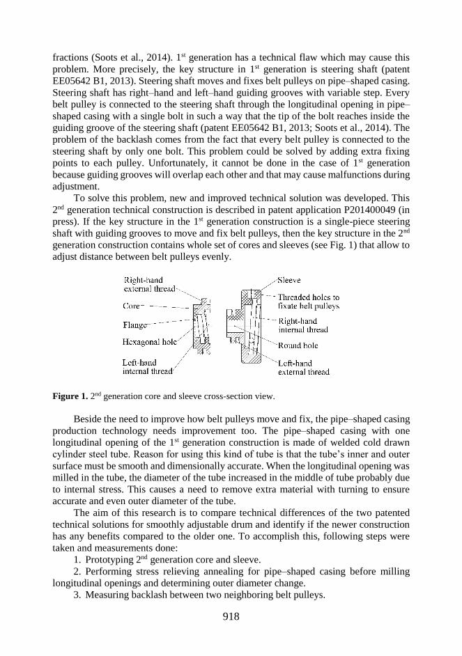
To solve this problem, new and improved technical solution was developed. This
2nd generation technical construction is described in patent application P201400049 (in
press). If the key structure in the 1st generation construction is a single-piece steering
shaft with guiding grooves to move and fix belt pulleys, then the key structure in the 2nd
generation construction contains whole set of cores and sleeves (see Fig. 1) that allow to
adjust distance between belt pulleys evenly.
Figure 1. 2nd generation core and sleeve cross-section view.
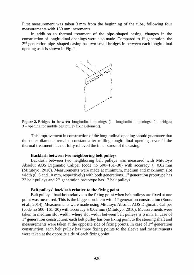
Beside the need to improve how belt pulleys move and fix, the pipe–shaped casing
production technology needs improvement too. The pipe–shaped casing with one
longitudinal opening of the 1st generation construction is made of welded cold drawn
cylinder steel tube. Reason for using this kind of tube is that the tube’s inner and outer
surface must be smooth and dimensionally accurate. When the longitudinal opening was
milled in the tube, the diameter of the tube increased in the middle of tube probably due
to internal stress. This causes a need to remove extra material with turning to ensure
accurate and even outer diameter of the tube.
The aim of this research is to compare technical differences of the two patented
technical solutions for smoothly adjustable drum and identify if the newer construction
has any benefits compared to the older one. To accomplish this, following steps were
taken and measurements done:
1. Prototyping 2nd generation core and sleeve.
2. Performing stress relieving annealing for pipe–shaped casing before milling
longitudinal openings and determining outer diameter change.
3. Measuring backlash between two neighboring belt pulleys.
Page 3
919
4. Measuring belt pulleys backlash relative to the fixing point when belt pulleys
are fixed at one point.
5. Measuring the torque that is required to regulate slot width between belt pulleys.
MATERIALS AND METHODS
For tests, prototypes of both generations are required. 1st generation remained from
our previous research (Soots et al., 2014), but 2nd generation prototype was specifically
manufactured for the purposes of this research.
Prototyping core and sleeve for 2nd generation
2nd generation core and sleeve given in Fig. 1 were manufactured by 3D printing.
3D printing is widely used for this kind of rapid prototyping (Wu et al., 2015). 3D
printing has many different technologies but in this case fused deposit modelling (FDM)
3D printing was used. This technology was chosen due to its ability to manufacture
complex parts quickly and easily with modest costs. The idea of FDM technology is to
create details layer by layer with thermoplastic filament (Palermo, 2013; Wu et al., 2015;
Stratasys Ltd., 2016). In this research Stratasys uPrint SE Plus was used and the printing
layer height was 0.254 mm (Stratasys Ltd., 2016). Reason why this 3D printer was
chosen is that it allows to print soluble support material in addition to the basic material.
3D printing doesn’t allow to print in the air and protruding parts of the details need to be
supported from below. Many FDM technology 3D printers print the parts and required
supports using the same material and after printing, supports are removed mechanically
thus, the detail surface quality may decrease. With Stratasys uPrint SE Plus 3D printer
the supports are printed with soluble material that are later removed in a special cleaning
machine. In this research Stratasys WaveWash support cleaning system was used to
remove supports from core and sleeve. To ensure core rotational movement in the
sleeves, clearance of 0.25 mm between the printed parts was chosen for 3D printing
(Peets, 2016).
Pipe–shaped casing manufacturing
2nd generation pipe–shaped casing is made of welded cold drawn cylinder tube that
is made of steel E355 (Novero S.P.A., 2016). Inner diameter of the used tube is 70 mm
and outer diameter 80 mm, according to manufacturer’s certificate (Novero S.P.A.,
2016). While 1st generation pipe–shaped casing has just one longitudinal opening,
2ndgeneration casing has three openings in order to add the extra belt pulleys’ fixing
points to the regulating element. Before milling the longitudinal openings in pipe–shaped
casing, the stress relieving annealing was performed. According to material certificate,
this must be done at temperature 580–630 °C and holding time of 1–2 min per mm of
plate thickness, but holding time must be at least 30 min (Fischer et al, 2010;
ThyssenKrupp, 2016). The thermal treatment was done at the local aluminium casting
workshop at 450 °C with duration of 4.5 hours. After the thermal treatment and milling,
the pipe–shaped casing’s outer diameter was measured with Nikon measuring arm
MCAx20 combined with laser scanner MMDx50. According to Nikon Metrology NV,
2016, accuracy of this laser scanning system is 50 µm. Obtained results were processed
with Nikon Focus software. Outer diameter was measured in five places on the tube.
Page 4
920
First measurement was taken 3 mm from the beginning of the tube, following four
measurements with 130 mm increments.
In addition to thermal treatment of the pipe–shaped casing, changes in the
construction of longitudinal openings were also made. Compared to 1st generation, the
2nd generation pipe–shaped casing has two small bridges in between each longitudinal
opening as it is shown in Fig. 2.
Figure 2. Bridges in between longitudinal openings (1 – longitudinal openings; 2 – bridges;
3 – opening for middle belt pulley fixing element).
This improvement in construction of the longitudinal opening should guarnatee that
the outer diameter remains constant after milling longitudinal openings even if the
thermal treatment has not fully relieved the inner stress of the casing.
Backlash between two neighboring belt pulleys
Backlash between two neighboring belt pulleys was measured with Mitutoyo
Absolut AOS Digimatic Caliper (code no 500–161–30) with accuracy ± 0.02 mm
(Mitutoyo, 2016). Measurements were made at minimum, medium and maximum slot
width (0, 6 and 10 mm, respectively) with both generations. 1st generation prototype has
23 belt pulleys and 2nd generation prototype has 17 belt pulleys.
Belt pulleys’ backlash relative to the fixing point
Belt pulleys’ backlash relative to the fixing point when belt pulleys are fixed at one
point was measured. This is the biggest problem with 1st generation construction (Soots
et al., 2014). Measurements were made using Mitutoyo Absolut AOS Digimatic Caliper
(code no 500–161–30) with accuracy ± 0.02 mm (Mitutoyo, 2016). Measurements were
taken in medium slot width, where slot width between belt pulleys is 6 mm. In case of
1st generation construction, each belt pulley has one fixing point to the steering shaft and
measurements were taken at the opposite side of fixing points. In case of 2nd generation
construction, each belt pulley has three fixing points to the sleeve and measurements
were taken at the opposite side of each fixing point.
Page 5
921
Required torque to regulate slot width between belt pulleys
Required torque to regulate the slot width between belt pulleys must be determined
in such a way that torque, rotational speed of the regulating lever, and angle of rotation
can be measured continuously at the same time. Tests were carried out with tensile
testing system Instron 5969, 1 kN load cell was used. Picture of the test setup to measure
required torque to regulate slot width between belt pulleys is shown in Fig. 3.
Figure 3. Picture of the test setup to measure required torque to regulate slot width between belt
pulleys.
As it is shown in Fig. 3, smoothly adjustable drum is fixed to the base of tensile
testing system. Regulating lever of drum is connected via grip to steel hawser. Diameter
of the regulating lever is 29.90 mm for 1st generation and 30.09 mm for 2nd generation
construction. For tests, tensile speeds of 30 mm min-1 and 130 mm min-1 were used.
When converted to the rotational speeds of the handle, 1st generation handle rotational
speeds are 0.32 min-1 and 1.384 min-1 and 2nd generation handle rotational speeds are
0.318 min-1 and 1.376 min-1. Handle rotation scope for 1st generation is 340 deg and for
2nd generation is 215 deg. All tests were performed without belts and without any force
on belt pulleys.
RESULTS AND DISCUSSION
Prototyping core and sleeve for 2nd generation
2nd generation 3D printed core and sleeve are shown in Fig. 4. In the figure also
support material (white) can be seen.
Figure 4. 2nd generation 3D printed core and sleeve.
Page 6
922
Results show that used 3D printing technology is suitable for function testing. With
used FDM technology, parts are printed layer by layer and threads’ surfaces are not
smooth. They remind little steps as can be seen in Fig. 4. The smaller is thickness of the
printed layer - the smaller are the steps. The used 3D printer allows to use minimal layer
thickness of 0.254 mm, so the steps are 0.254 mm high. This affects parts surface
roughness and thereby core movement inside the sleeves.
Chosen clearance between the printed parts was sufficient to obtain movement
between them and only minor mechanical polishing and oil lubrication was required.
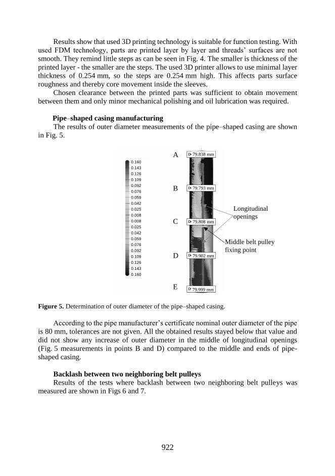
Pipe–shaped casing manufacturing
The results of outer diameter measurements of the pipe–shaped casing are shown
in Fig. 5.
Figure 5. Determination of outer diameter of the pipe–shaped casing.
According to the pipe manufacturer’s certificate nominal outer diameter of the pipe
is 80 mm, tolerances are not given. All the obtained results stayed below that value and
did not show any increase of outer diameter in the middle of longitudinal openings
(Fig. 5 measurements in points B and D) compared to the middle and ends of pipe-
shaped casing.
Backlash between two neighboring belt pulleys
Results of the tests where backlash between two neighboring belt pulleys was
measured are shown in Figs 6 and 7.
A
Longitudinal
openings
Middle belt pulley
fixing point
B
C
D
E
0.160
0.143
0.126
0.109
0.092
0.076
0.059
0.042
0.025
0.008
0.008
0.025
0.042
0.059
0.076
0.092
0.109
0.126
0.143
0.160
79.838 mm
79.793 mm
79.808 mm
79.902 mm
79.999 mm
Page 7
923
Figure 6. 1st generation backlash between two neighboring belt pulleys.
Figure 7. 2nd generation backlash between two neighboring belt pulleys.
Results of tests where backlash between two neighboring belt pulleys where
measured shows that:
1. 1st generation backlash between two neighboring belt pulleys is smaller than that
of 2nd generation.
a. at minimum slot width between belt pulleys, 1st generation average backlash
between two neighboring belt pulleys is 0 mm. In case of 2nd generation,
average backlash is 0.40 mm at the same conditions.
b. at average slot width between belt pulleys, 1st generation average backlash
between two neighboring belt pulleys is 0.42 mm. In case of 2nd generation,
average backlash is 0.61 mm at the same conditions.
c. at maximum slot width between belt pulleys, 1st generation average backlash
between two neighboring belt pulleys is 0.36 mm. In case of 2nd generation,
average backlash is 0.74 mm at the same conditions.
2. 2nd generation the outermost belt pulley’s backlash relative to the middle one
depends on the backlashes of other belt pulleys that are between them. This is due to the
0
1
1 2 3 4 5 6 7 8 9 10 11 12 13 14 15 16 17 18 19 20 21 22 23
Ba
ckla
sh
, m
m
Belt pulley no
1. Belt pulleys medium slot width (▲ data points) 2. Belt pulleys maximum slot width
(■ data points) 3. Belt pulleys minimum slot width (♦ data points)
0.00
0.50
1.00
1.50
2.00
2.50
1 2 3 4 5 6 7 8 9 10 11 12 13 14 15 16 17
Ba
ckla
sh
, m
m
Belt pulley no
1. Belt pulleys medium slot width (▲ data points) 2. Belt pulleys maximum slot width
(■ data points) 3. Belt pulleys minimum slot width (♦ data points)
Page 8
924
constructional peculiarities of II generation. Particularly, that outermost sleeve is
connected to the middle sleeve through all cores and sleeves between them and the
clearances of all the threads accumulate.
3. 1st generation outermost belt pulley backlash relative to the middle one doesn’t
depend on backlash of other belt pulleys because every thread is independent on a single
solid steering shaft.
4. In case of both generations, average backlashes between two neighboring belt
pulleys depend on the slot width between belt pulleys.
Belt pulleys backlash relative to the fixing point
Test results for belt pulleys backlash relative to the fixing point are given in the
Figs 8 and 9.
Figure 8. 1st generation belt pulleys backlash with medium slot width, measured at the opposite
side of belt pulley fixing point.
Figure 9. 2nd generation belt pulleys backlash with medium slot width, measured at three
opposite sides of belt pulleys fixing points.
Obtained test results about belt pulleys backlash relative to the fixing point show
that:
1. 1st generation belt pulleys’ backlash (maximum 10.57 mm) is greater than 2nd
generation (maximum 2.31 mm).
2. 1st generation belt pulleys’ backlash decreases away from the middle of pipe–
shaped casing where the middle belt pulley is fixed.
3. 2nd generation belt pulleys’ backlash increases away from the middle of pipe–
shaped casing where the middle belt pulley is fixed.
8
9
10
11
1 2 3 4 5 6 7 8 9 10 11 12 13 14 15 16 17 18 19 20 21 22 23
Ba
ckla
sh
, m
m
Belt pulley no
0
1
2
3
1 3 5 7 9 11 13 15 17
Bac
kla
sh
, m
m
Belt pulley no
Page 9
925
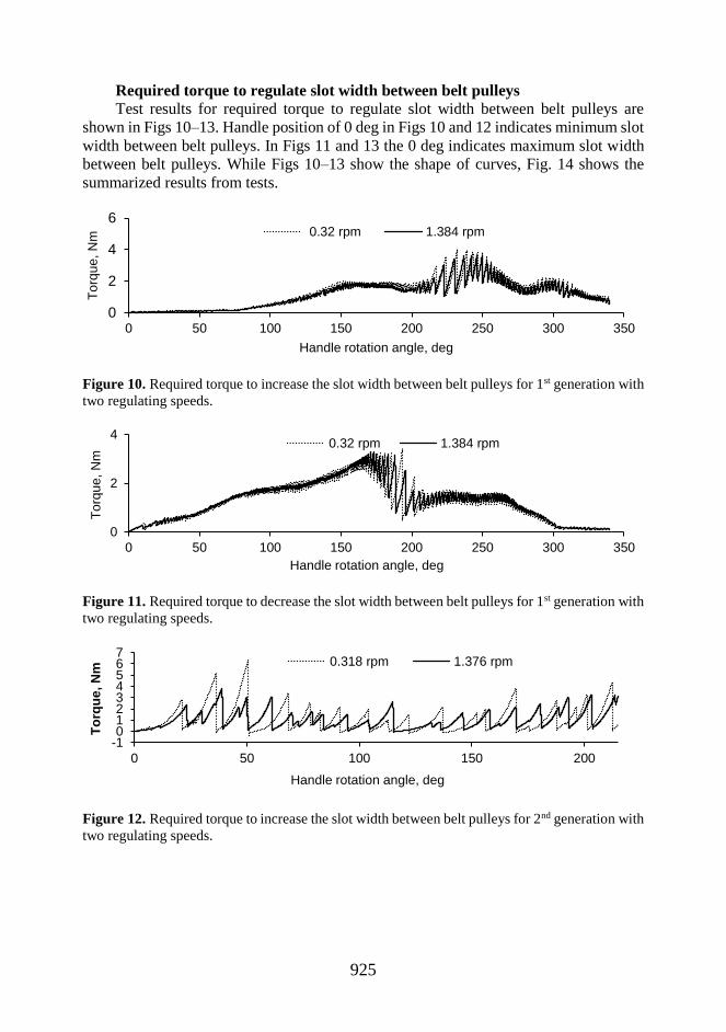
Required torque to regulate slot width between belt pulleys
Test results for required torque to regulate slot width between belt pulleys are
shown in Figs 10–13. Handle position of 0 deg in Figs 10 and 12 indicates minimum slot
width between belt pulleys. In Figs 11 and 13 the 0 deg indicates maximum slot width
between belt pulleys. While Figs 10–13 show the shape of curves, Fig. 14 shows the
summarized results from tests.
Figure 10. Required torque to increase the slot width between belt pulleys for 1st generation with
two regulating speeds.
Figure 11. Required torque to decrease the slot width between belt pulleys for 1st generation with
two regulating speeds.
Figure 12. Required torque to increase the slot width between belt pulleys for 2nd generation with
two regulating speeds.
0
2
4
6
0 50 100 150 200 250 300 350
To
rqu
e, N
m
Handle rotation angle, deg
0.32 rpm 1.384 rpm
0
2
4
0 50 100 150 200 250 300 350
To
rqu
e, N
m
Handle rotation angle, deg
0.32 rpm 1.384 rpm
-101234567
0 50 100 150 200
To
rqu
e, N
m
Handle rotation angle, deg
0.318 rpm 1.376 rpm
Page 10
926
Figure 13. Required torque to decrease the distance between belt pulleys for 2nd generation with
two regulating speeds.
Figure 14. Summarized results for required torque to regulate the slot width between belt pulleys.
Obtained test results for required torque to regulate slot width between belt pulleys
show that:
1. With 1st generation the required torque to regulate is maximum at the medium
slot width when decreasing or increasing the slot width between belt pulleys.
2. With 2nd generation the required torque to regulate is stepped because the thread
surfaces of 3D printed parts are also stepped, not smooth. Every step starts with smooth
rise and ends with rapid decrease.
3. According to test results the 2nd generation maximum required torque for
regulate is higher than 1st generation. With 2nd generation 6.35 Nm is required when
increasing slot width at rotational speed 0.318 rpm but with 1st generation 4.01 Nm is
required when increasing slot width at rotational speed 0.32 rpm.
4. Mean required torque to regulate is smaller with 2nd generation in both regulating
directions and with both rotational speeds.
5. 2nd generation required torque to regulate dispersion is bigger than it is with 1st
generation with both regulating speeds and direction as it is presented in Table 1 (raw-
data is obtained from Instron tensile testing system and standard deviation is calculated
in MS Excel).
6. For both generation faster regulating speed decreases required torque to regulate
dispersion and it’s maximum value.
-10123456
0 50 100 150 200
To
rqu
e, N
m
Handle rotation angle, deg
0.318 rpm 1.376 rpm
-1
1
3
5
7
0.32 1.384 0.318 1.376 0.32 1.384 0.318 1.376
I gen decreasing II gen decreasing I gen increasing II gen increasing
To
rqu
e, N
m
Handle rotational speeds in different rotational directions, rpm
Page 11
927
Table 1. Standard deviations of required torque for regulating distance between belt pulleys at
different regulating speeds for 1st and 2nd generation
1st gen decreasing 2nd gen decreasing 1st gen increasing 2nd gen increasing
0.32
rpm
1.384
rpm
0.318
rpm
1.376
rpm
0.32
rpm
1.384
rpm
0.318
rpm
1.376
rpm
Standard
deviation, σ 0.79 0.75 1.04 1.00 0.84 0.72 1.23 0.82
In conclusion, it can be said that 2nd generation fixes the biggest problem that 1st
generation has. 1st generation belt pulleys’ backlash relative to the fixing point is a
maximum of 10.57 mm but 2nd generation has a maximum belt pulleys’ backlash relative
to the fixing point of 2.31 mm. Desired backlash relative to the fixing point should be
maximum of 0.5 mm at all slot widths. But on the other hand 2nd generation has some
new problems. Test results show that the technology that is used to prototype core and
sleeve for 2nd generation don’t suit very well in this case and more suitable technology
must be used. It is essential to ensure smooth thread surface finish and smaller clearance
between core and sleeve threads to avoid the accumulating backlash between two
neighboring belt pulleys and ensure more even and lower required torque to regulate slot
width between belt pulleys. Because of required clearance between 3D printed parts,
backlash between two neighboring belt pulleys is bigger than it’s should be and it
depends on slot width between belt pulleys. Desired backlash between two neighboring
belt pulleys should be maximum of 0.5 mm and it should not be dependent on slot width
between belt pulleys. Decreasing clearance between core and sleeve will have positive
affect on belt pulleys backlash relative to the fixing point and especially on backlash
between two neighboring belt pulleys. Overall 2nd generation technical solution showed
promising results and has more potential than 1st generation.
CONCLUSION
This paper compares technical characteristics of two patented technical solutions
of smoothly adjustable drum and brings out their pros and cons. Main constructional
differences are:
1. 1st generation key structure is single one-piece steering shaft with right–hand
and left–hand guiding grooves with variable step while 2nd generation has multiple sets
of cores and sleeves to regulate distance between belt pulleys.
2. 2nd generation has improved pipe-shaped casing construction and preparation
method.
Named 2nd generation developments has following effects:
1. Two extra fixing points to every 2nd generation belt pulley to the key structure is
added compared to 1st generation.
2. The outer diameter of 2nd generation pipe–shaped casing’s is constant across it’s
length.
3. Belt pulleys’ average backlash relative to the fixing point of 2nd generation is
smaller. Maximum belt pulleys’ backlash relative to the fixing point decreased by 8.26
mm.
4. Backlash between two neighboring belt pulleys of 2nd generation is greater than
that of 1st generation and it depends on slot width between belt pulleys.
Page 12
928
5. Required torque to regulate slot width between belt pulleys of 2nd generation is
greater and stepped.
Results show that the last two negative effects of the 2nd generation are caused by
the peculiarities of the chosen prototyping method for the key structure and these can be
solved by using more suitable manufacturing method. Further research with 2nd
generation is necessary to study if these arguments are true.
REFERENCES
Fischer, U., Gomeringer, R., Heinzler, M., Kilgus, R., Näher, F., Oesterle, S., Paetzold, H. &
Stephan, A. 2010. Mechanical and Metal Trades Handbook, (2nd English edition). Verlag
Europa Lehrmittel, Germany, 428 pp (in English).
Lakewood Process Machinery 2016. (February 26) URL: http://lakewoodpm.com
Mitutoyo 2016. (March 3). URL: http://dl.mitutoyo.eu/HE/eBook/en_us/index.html?page=180.
Nikon Metrology NV. 2016. (March 3)
URL: http://www.nikonmetrology.com/en_EU/Products/Laser-Scanning/Handheld-
scanning/ModelMaker-MMDx/(specifications).
Novero, S.P.A. 2016. (February 19). URL: http://www.noverotubi.com
Olt, J. 2015. Põllumajandustehnika I. Põllundusmasinad. Kuma Print, Paide, 208 pp. (in
Estonian).
Olt, J. & Soots, K. 2013. Patent EE 05642 B1. 2013. Berry sorter, B07B13/065.
Palermo, E. 2013. Fused Deposition Modeling: Most Common 3D Printing Method. Livescience.
URL: http://www.livescience.com/39810-fused-deposition-modeling.html.
Peets, A. 2016. (February 26). Vabavaraline 3D printimine õppematerjal.
URL: https://moodle.hitsa.ee/course/view.php?id=14120. (in Estonian).
Soots, K., Maksarov, V. & Olt, J. 2014. Continuously adjustable berry sorter. Agronomy
Research 12(1), 161–170.
Soots, K., Olt, J. 2016. Non-stationary processing center for small and medium sized blueberry
farms. Research in Agricultural Engineering. (in press).
Soots, K. & Olt, J. 2014. Patent application P201400049. Belt sorter. (in press).
Stratasys Ltd. 2016. (February 26). URL: http://www.stratasys.com.
ThyssenKrupp Materials International 2016. (February 22). URL: http://www.s-k-
h.com/media/de/Service/Werkstoffblaetter_englisch/Dickwand__Hohlprofile/E355R_engl
.pdf.
Wu, W., Geng, P., Li, G., Zhao, D., Zhang, H. & Zhao, J. 2015. Influence of Layer Thickness
and Raster Angle on the Mechanical Properties of 3D-Printed PEEK and a Comparative
Mechanical Study between PEEK and ABS. Materials 8, 5834–5846.