1 FINAL TECHNICAL REPORT September 1, 2008, through August 31, 2009 Project Title: DEVELOPMENT OF CARBON NANOTUBE BASED CATALYST SUPPORT FOR FISCHER TROPSCH SYNTHESIS ICCI Project Number: 08-1/ER6 Principle Investigator: Saikat Talapatra, Southern Illinois University Carbondale Project Manager: Debalina Dasgupta, ICCI ABSTRACT The primary objective of this research proposal was to develop a non-oxide based catalyst support for Fischer Tropsch (FT) synthesis. The goal was to synthesize various carbon nanotube (CNT) architectures that can be utilized as supports for Fischer Tropsch synthesis catalysts. Various architectures of CNTs such as free standing aligned multiwalled CNTs (MWNT) as well as MWNT paper were synthesized and characterized using electron microscopy and Raman spectroscopy. These CNT architectures were loaded with Fe and Co (standard FT catalysts) using single step electrochemical deposition process. Preliminary FT synthesis experiments were performed in an in-house fabricated FT reactor equipped with gas handling system, temperature and gas flow controls as well as FT liquid collection reservoirs. Our results indicate that the conversion of CO and H 2 obtained with as-produced CNTs as well as FT catalyst loaded CNTs are orders of magnitude higher than the conventional FT catalyst. The product distribution on these CNT samples favored chain growth as compared to the conventional catalysts. From these results, we can conclude that these novel nano-structured carbon materials offer a new breed of non-oxide catalyst supports with superior performance for FT synthesis.
Transcript
1
FINAL TECHNICAL REPORT September 1, 2008, through August 31, 2009
Project Title: DEVELOPMENT OF CARBON NANOTUBE BASED CATALYST
SUPPORT FOR FISCHER TROPSCH SYNTHESIS ICCI Project Number: 08-1/ER6 Principle Investigator: Saikat Talapatra, Southern Illinois University Carbondale Project Manager: Debalina Dasgupta, ICCI
ABSTRACT
The primary objective of this research proposal was to develop a non-oxide based catalyst support for Fischer Tropsch (FT) synthesis. The goal was to synthesize various carbon nanotube (CNT) architectures that can be utilized as supports for Fischer Tropsch synthesis catalysts. Various architectures of CNTs such as free standing aligned multiwalled CNTs (MWNT) as well as MWNT paper were synthesized and characterized using electron microscopy and Raman spectroscopy. These CNT architectures were loaded with Fe and Co (standard FT catalysts) using single step electrochemical deposition process. Preliminary FT synthesis experiments were performed in an in-house fabricated FT reactor equipped with gas handling system, temperature and gas flow controls as well as FT liquid collection reservoirs. Our results indicate that the conversion of CO and H2 obtained with as-produced CNTs as well as FT catalyst loaded CNTs are orders of magnitude higher than the conventional FT catalyst. The product distribution on these CNT samples favored chain growth as compared to the conventional catalysts. From these results, we can conclude that these novel nano-structured carbon materials offer a new breed of non-oxide catalyst supports with superior performance for FT synthesis.
2
EXECUTIVE SUMMARY
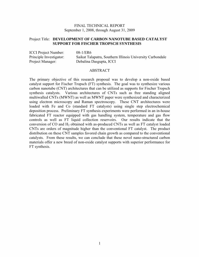
The ongoing energy crisis and the need for commercially viable clean energy sources have presented themselves as two of the foremost challenges of the twenty first century. Coal represents a major energy source if the energy can be extracted in an environmentally and ecologically safe manner. The use of direct and indirect liquefaction processes of coal would result in making coal a source of liquid fuels and precursor to several chemicals. FT synthesis process, a catalyzed chemical reaction, can convert a mixture of carbon monoxide and hydrogen (commonly known as synthesis gas produced during coal gasification) to a wide range of liquid hydrocarbons. When this process is combined with a suitable coal gasification technology upstream and a refining process downstream, gasoline and diesel fuels with low trace and sulfur components but with high octane and cetane numbers, respectively, can be produced. In the Fischer Tropsch synthesis reaction, CO and H2 react to form methyl radicals that combine to form hydrocarbons. The FT synthesis process consists of five basic steps: a) reactant adsorption, b) chain initiation, c) chain growth, d) chain termination, and e) product desorption. The mechanism of Fisher Tropsch synthesis is shown in Figure 1. It is seen in the mechanism that water is a byproduct of the primary FT synthesis reaction. However, carbon dioxide may be a byproduct of the primary FT reaction if the availability of hydrogen at the reactions site is low. Thus, the hydrogen spillover onto the support and its ability to weakly adsorb these hydrogen moieties is a determining factor for the carbon efficiency. In any kind of catalytic process, the catalysts are dispersed on high surface area materials, known as the catalyst support. The support provides mechanical strength to the catalysts in addition to boosting the specific catalytic surface and enhancing the reaction rates. The efficiency of FT synthesis process lies on the activity of metal catalyst as well as the catalyst support. The two primary active catalysts for Fischer Tropsch synthesis are cobalt and iron, typically prepared over a variety of support materials such as -alumina, -alumina, titania, and zirconia. Typical state of the art support materials are oxides, which pose severe drawbacks towards the process efficiency of FT synthesis. For example, in cases where there is a strong support to catalyst interaction such as in - alumina, which is a popular choice for catalyst support, the reduction of the catalyst to their metallic form is greatly hindered and requires higher temperatures and time. Higher temperatures not only mean higher energy demand for catalyst preparation but may actually result in the sintering of the catalysts that would cause it to deactivate. Carbon nanotubes (CNTs), due to their unique one dimensional structure, offer very high specific surface areas (in some cases up to six to seven times more than - alumina, and
Figure 1. The FT process.
3
possess outstanding mechanical as well as thermal properties and are chemically very stable. These properties make them ideal materials for applications such as catalyst support for FT synthesis. Exploratory studies in the synthesis of FT catalysts on CNT supports and the evaluation of these catalysts for CO hydrogenation were conducted as a part of this project. Specific aims of this exploratory research were to synthesize various architectures of carbon nanotubes, discover innovative routes to load these architectures with FT catalyst, and perform preliminary FT synthesis experiments on these CNT supported catalysts. CNTs can be defined as carbon whiskers, which are tubules of nanometer dimensions with properties close to that of an ideal graphite fiber. Due to their distinctive structures they can be considered as matter in one-dimension (1D). In other words, a carbon nanotube is a honeycomb lattice rolled on to itself, with diameters of the order of nanometers and length of up to several micrometers. Generally, two distinct types of CNTs exist as shown in Figure 2, depending whether the tubes are made of more than one graphene sheet (multi walled carbon nanotube, MWNT) or only one graphene sheet (single walled carbon nanotube, SWNT). Irrespective of the number of walls, CNTs are envisioned as the new engineering materials which possess superior mechanical strength, exotic electrical properties and superb chemical and thermal stability needed for a variety of applications. As far as applications in catalysis are concerned, CNTs offer extraordinary advantages over conventional supports in terms of the available specific surface areas which may range from 50 m2/g – 1600 m2/g depending on the type of CNTs. It is competitive in providing adequate mechanical strength and is expected to reduce hot spots on the active catalyst in view of its excellent heat conductivity. We have used chemical vapor deposition technique for growing aligned architectures of
CNTs. CVD processes are widely used to produce carbon nanotubes at low cost and high quality. More importantly, it is able to produce high purity nanotubes by in-situ etching of amorphous carbon during the growth process. For CVD, xylene, ethylene or acetylene is used as the common hydrocarbon precursor and some form of organometallic compound such as ferrocene as the catalyst precursor. Typically, the growth of CNTs is achieved by vapor phase catalyst delivery CVD method. In this method a solution containing a carbon source and a
Figure 2. Electron microscope image of (a) SWNT bundle. (Inset) Schematics of SWNT bundle. (b) MWNT showing its multiple walls and hollow core. (Inset) Schematic of a MWNT.
a b
Figure 3. (a) Aligned block of MWNT (scale = 5mm). (b) CNT paper (scale = 20 mm).
4
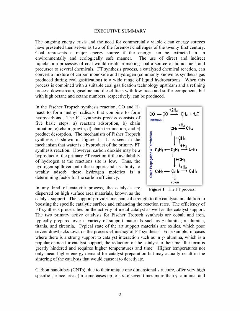
catalyst is vaporized and flown over a substrate kept inside a furnace. The temperature of the furnace is tuned (700 – 900oC) such that the catalyst particles precipitate on the substrate from the vapor and carbon atoms disassociate from the carbon source. The disassociated carbon atoms stick to the catalyst particles and form subsequent carbon chains to facilitate CNT growth. We have employed an in-house developed air assisted vapor phase catalyst delivery CVD method for growing CNTs. By using this method growth rate of CNTs can be dramatically enhanced to about three times than that in a conventional CVD process. In our experiments we have used ferrocene and xylene for growing vertically aligned CNTs (Figure 3a). These CNTs were used to form free standing CNT papers (Figure 3b) for loading FT catalysts. The CNT papers were loaded with catalysts using electrodeposition technique. The FT experiments were conducted at two different temperatures of 300 oC and 350 oC
with a 2 hour residence time of the gas mixture on the catalysts. The data presented in Figure 4 demonstrates the significant improvement in conversion of the reactants by using as-produced MWNT carbon nanotubes and Fe and Co loaded CNT structures as catalysts when compared to conventional FT catalysts. The product distribution on these CNT samples favored chain growth as compared to the conventional catalysts. The results of the preliminary FT synthesis studies shown in Figure 4 provide ample
evidence of superior specific activity (kmol CO converted/g of catalyst) of CNT supported catalysts in comparison to Fe-Zn-K/alumina for CO hydrogenation.
Figure 4. Comparison of syngas conversion for different catalysts used.
5
OBJECTIVES
The overall goal of this research was to investigate the scope of utilizing CNTs as supports for FT catalysts. The specific objectives of the project were a) to synthesize various architectures of CNTs, b) employ various techniques to load the CNTs with iron and cobalt, two well known FT catalysts, and c) to evaluate performance of these catalysts in FT synthesis processes.
INTRODUCTION AND BACKGROUND
Fischer Tropsch synthesis process converts a mixture of carbon monoxide and hydrogen (commonly known as synthesis gas) to a wide range of straight chained and branched olefins and paraffins and oxygenates1-8. The combination of this process with suitable coal gasification technology upstream and a refining process downstream will result in the production of gasoline and diesel fuels with low trace and sulfur components but with high octane and cetane numbers, respectively. The efficiency of the FT synthesis process is dependent on the type of catalyst1, 3, 8 used. The two primary active catalysts for FT synthesis are cobalt and iron. Cobalt has a high activity towards these reactions1, 4-7 and is particularly useful for synthesis gas with a H2: CO ratio of 2:1 since it is stoichiometrically favored for FT synthesis. The gasification of coal without any intermediate process would result in a H2:CO ratio of 0.67 to 1 and requires a water gas shift (CO +H2O = CO2 + H2) reaction to enhance this ratio to 2. However, since cobalt is not an efficient water gas shift catalyst it is often not recommended for coal to liquid fuels synthesis. Iron, on the other hand, is an efficient water gas shift catalyst but has lower activity towards the formation of longer chained hydrocarbons when compared to cobalt. To overcome these deficiencies, these active phases are often promoted with copper and potassium carbonate to enhance their water gas shift activity, promote the FT synthesis and to improve the reducibility of the catalysts to their metallic states. Another important component of the catalysts is the support8-18 onto which they are loaded. Although they are not the active phases on which the reactions take place, the supports have multiple functions that affect catalyst activity. In addition to providing mechanical strength to the catalysts, supports enhance the specific catalytic surface and reaction rates by effectively exploiting H2 spillover such that a high hydrogen concentration is available near the catalyst surface. The most commonly used catalyst support is -alumina although other supports such as silica, -alumina, titania, and zirconia are also used. - alumina is generally the choice for catalysts supports since it provides a high surface area (~150 m2/g) and allows a high dispersion of the catalyst on the surface. However, -alumina has a strong interaction effect with the catalyst12-14 that is detrimental to activity towards FT synthesis. Carbon nanotubes possess several advantages19-22 over conventional catatyst support materials. They have very high specific surface areas23, 24 and are resistive to acidic or basic media. They are stable at high temperatures (> 700 oC in inert atmosphere). The
6
surface curvature and the pore structure, which are important parameters when determining shape selectivity in catalysis, can easily be tailored. The chemical nature of the CNT surface can be modified for increased catalyst loading and activity. CNTs with their superior properties can be synergistically utilized with known active FT catalysts to enhance the rate of hydrocarbon synthesis and C5+ selectivity. In addition to all the advantages described earlier, the examined catalysts structures are of special importance to FT synthesis due to their high active phase to support weight without loss of surface area. This is particularly useful when combined with technologies such as circulating fluidized bed FT reactors, that can achieve higher throughputs, due to the use of catalyst structures with a high active phase to support weight ratio, for a given catalyst surface. The development of coal to liquid fuels technology (reactor and catalyst) that can commercially compete with the oil prices will provide a huge impetus to Illinois coal, especially due to the ability of the overall process to produce low sulfur liquids from high sulfur IL coal.
EXPERIMENTAL PROCEDURES
PROJECT RATIONALE AND APPROACH In the past, activated carbon (AC) has been used as non-oxide based FT catalyst support. Though AC has a very high surface area (~ 1800 m2/g), most of the available surface area resides in pore with pore sizes less than 2 nm which limits the accessibility of the catalyst to a significant portion of the surface. Further, the microporous texture of these materials often results in the aggregation of the metal catalyst on the outer surface. In comparison, CNTs offer moderate to high specific surface areas (ranging from 50m2/g – 1600m2/g depending on the type of CNTs) with mesopores and micropores which makes metal functionalization easier. Their tubular structure is also capable of providing favorable distribution of catalyst on their surfaces. If uniform distribution of the catalyst on CNT surfaces can be achieved, there is a possibility that the activity of CNT supported catalyst will be enhanced when compared to ACs. CVD grown CNTs have nanoscale dimensions and hence have high specific surface areas, high thermal & chemical stability. These properties are suitable for developing them as catalyst support in Fischer Tropsch synthesis. Due to the low temperatures of the growth process, CVD grown CNTs have inherent surface defects in the form of disordered graphitic layers. These defects known as arrows, make their nanoscale surfaces ideal platform for functionalization with different chemical species. Simple routes can be used to attach nanoclusters of various metals such as iron, cobalt etc. on these surfaces. The various structures of synthesized CNTs possess surface defects. These defect loaded CNTs, when used as an electrode in an electro-chemical bath, are envisioned to exhibit enhanced electric fields in the vicinity of the defects and therefore will act as nucleation sites for the metal nanoclusters. Further, since this process provides flexibility and control on the size of the catalyst deposited, the size of the metal clusters can be easily controlled by varying the deposition time. Surface-modified carbon nanotube electrodes can then be used to obtain favorable dispersion of the catalyst on the CNT surfaces.
7
METHODOLOGY Synthesis of free standing aligned MWNTs and MWNT paper For accomplishing this task, we have used chemical vapor deposition (CVD) process currently available in our lab (Figure 5). CVD processes are widely used to produce carbon nanotubes at low cost and high quality. More importantly, it is able to produce high purity nanotubes by in-situ etching of amorphous carbon during the growth process. The method we used utilizes a solution of a carbon source (xylene) and a catalyst (ferrocene). The solution was vaporized and passed over (using argon/ hydrogen (85% Ar)) a silicon dioxide substrate placed inside a furnace. The temperature of the furnace was maintained between 700 – 900oC so that the catalyst particles precipitate on the substrate from the vapor and carbon atoms disassociate from the carbon source. The disassociated carbon atoms stick to the catalyst particles and form subsequent carbon chains to facilitate CNT growth. We also found that the growth rate of the MWNTs can be dramatically enhanced, by introducing a small amount of air along with the carrier gas. The nanotubes were removed from the substrates and sonicated for few hours in ethyl alcohol. 100 ml of deionized (DI) water was added into the solution and vacuum filtered through a porous membrane to obtain free standing random network of CNTs. Catalyst Loading We have utilized the process of electrodeposition for loading the catalyst on the free standing random networks of CNTs. Fe/Co was electrodeposited on these CNT architectures. The electrodeposition was carried out using a classical three-electrode potentiostat system with an Ag/AgCl electrode as a reference electrode and a platinum wire as a counter electrode. Thin strips of the CNT mats, shown in Figure 3, were used as the working electrode. For fabricating the working electrode, a strip of the CNT mat was cut from the free standing CNT mat and was attached on one end of a conductive copper tape. The CNT strip attached to the copper tape was dipped in the electrolyte containing iron. The other end of the copper tape was attached to the electrical leads connected to the potentiostat. An EG&G Princeton Applied Research potentiostat/galvanostat Model 2263 was used to control the electrodeposition process. The electrolyte was prepared by mixing 5 g of iron and 4.5 g of boric acid in 150 mL of water. The deposition was carried out by applying at -1.0 V on the cathode with respect to the reference electrode. The quantity of Fe loading was controlled by varying the time of the deposition.
Figure 5. CVD reactor used for production of CNTs.
8
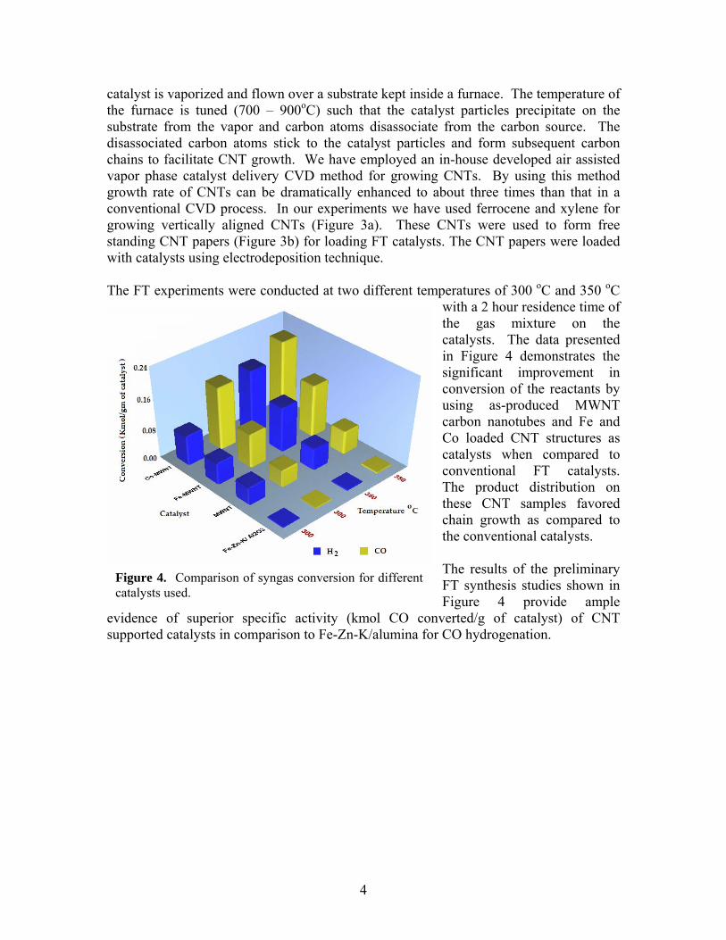
Characterization The CNTs produced were characterized using Transmission Electron Microscopy (TEM), Scanning Electron Microscopy and Raman Spectroscopy. Apart from these using these characterization tools, CNTs were also examined using energy dispersive spectroscopy (EDS) for structural and compositional investigation. Fischer-Tropsch Synthesis FT synthesis was carried out in a ½” dia X 16” tall tubular fixed bed reactor. The reactor was packed with the CNT supported catalyst. Syngas with a H2:CO ratio of 2:1 was introduced at different flow rates (to vary the residence time) at temperatures and pressures ranging from 200-400 oC and 14.7 psig -300 psig, respectively. Thermocouples coupled with temperature controllers were used to measure and control the reaction zone temperature. A backpressure regulator with a pressure transducer was employed to maintain the desired pressures. A schematic of the setup is shown in Figure 6.
RESULTS AND DISCUSSION Task 1. Synthesis of Carbon Nanotubes Using an air assisted growth process (as discussed in the previous section), we were able to grow a free standing ultra long robust structure of vertically aligned carbon nanotubes. Optical images, scanning electron microscopy (SEM) and transmission electron microscopy (TEM) images of typical aligned CNTs grown using this process are shown
Figure 6. Schematic of the reactor used for studying FT process.
9
in Figure 7. This method is ideal for growing gram quantities of aligned CNTs. For obtaining free standing random network of CNTs, the CNTs were removed from substrates and treated with hydrogen peroxide for more than 20 hrs. They were then immersed in hydrochloric acid for 24 hrs. After removal from hydrochloric acid, the CNTs were sonicated for few hours in ethyl alcohol to neutralize the effect of acid. 100 ml of DI water was added into the sonicated solution and vacuum filtered through a porous membrane to obtain free standing random network of CNTs. The results are shown in Figure 8.
Task 2. Catalyst Loading We have used electrodepostion techniques to attach metal clusters on CNTs. SEM images for various deposition times are presented in Figure 9. It can be seen from the figure that a deposition time greater than 10 mins leads to the formation of bulk cluster and deposition time between 5-10 mins forms nanosized clusters on the CNTs. Similar experiments were also performed for depositing cobalt on the CNT surfaces. Task 3. Characterization The results of SEM and TEM characterization of aligned MWNT samples are presented in Figure 10. In Figure 10a, we have presented an SEM image of blocks of aligned MWNTs peeled off from the silicon substrates on which they were grown. In Figure 10b,
Figure 9. CNT network after Fe loading. (2 m).
Figure 7. (a) Ultra long aligned CNTs. (b) SEM image of a CNT bundle and (c) TEM: hollow core & multiple graphitic layers of a CNT are shown.
60 m
a
b c
40 nm
Figure 8. (a) Optical image of random CNT network (b) SEM image of the network showing entangled bundle of CNTs (scale 2µm).
10
TEM images of the MWNTs are presented. The inset of this figure is a higher magnification image of the nanotubes showing hollow tubular structure of the CNTs. The diameter distributions of the MWNTs were also determined from the TEM characterization. A typical diameter distribution is shown in Figure 10c. We found that the MWNT diameters values for a growth time between 30-45 mins ranged between 20-40 nm.
The MWNTs were also characterized using Raman Spectroscopy. The first order Raman spectral features observed the MWNT samples are shown in Figure 11. In the higher frequency region (wavenumbers > 1200 cm-1) two strong peaks between 1300 cm-1 and 1600 cm-1 were observed. A typical peak observed for all the samples was centered around ~ 1350 cm-1. This corresponds to the disorder induced, D-band of graphite and is due to the presence of amorphous carbon, defects in nanotubes and other carbon materials present in the sample. Along with this peak, another strong peak with values close to that of the G band (corresponding to the graphite E2g optic mode) of graphite at ~1582 cm-1 was
also observed in all the samples synthesized. This mode is due to the in-plane bond stretching motion of pairs of sp2 carbon atoms and can lie anywhere between 1500 cm−1 and 1630 cm−1. Therefore, the peaks within this range in our samples were assigned to be the G band of graphite. These Raman spectroscopy results are signature of multiwalled CNTs. EDS spectra obtained from the MWNTs produced described in these two tasks contain ~ 5% by weight of iron. Task 4. Fischer-Tropsch Synthesis For performing the FT synthesis experiments, a ½” dia X 16” long reactor system equipped with temperature, flow and pressure controllers and both product liquid and gas collection systems for the analysis of CNTs as catalysts for various gas phase reactions was specifically designed with support from Dr. Kanchan Mondal, Mechanical Engineering, SIUC. A digital image of the reactor is shown in Figure 12.
100 m
50 nm
1 m
Figure 10. SEM, TEM characterization and the diameter distribution of CNTs.
Figure 11. First order Raman spectra of the aligned CNTs.
11
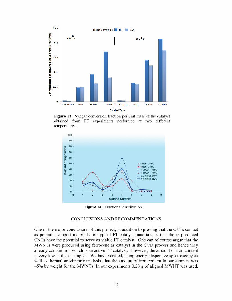
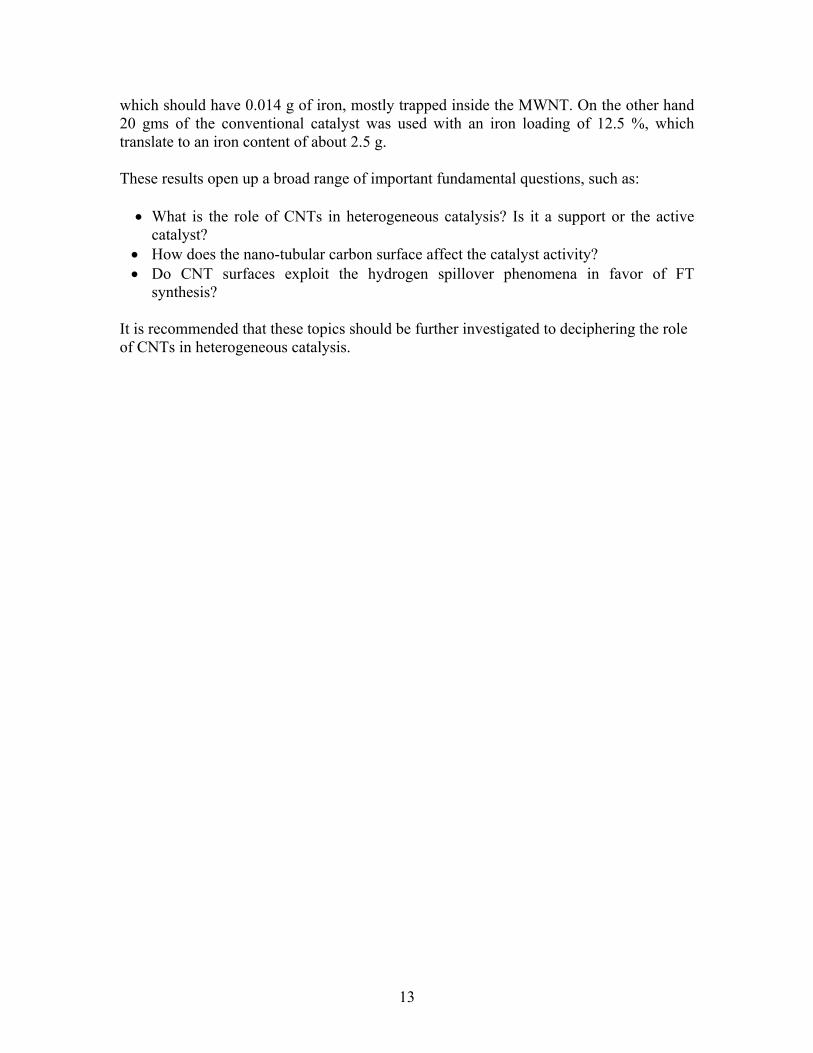
FT experiments were conducted at 200 psi at two different temperatures (300 oC and 350 oC). The residence time in the reactor was 2 hours. We tested as-produced MWNT, iron loaded MWNT (Fe-MWNT) and cobalt loaded MWNT (Co-MWNT) in this reactor. For comparison we also conducted FT experiments on conventional catalysts Fe-Zn-K/ Al2O3. The results are presented in Figure 13. In Figure 13, CO conversions of as-produced MWNT and Fe and Co loaded MWNT investigated at two different temperatures are shown. It is interesting to note that the CO conversion per unit gram of catalyst ranged from 0.05-0.23 kmol/g of catalyst which correspond to a specific CO conversion percent of ~130-~420 depending on the type of catalyst type and the reaction temperature. These results of CNT based samples show over an order of magnitude improvement in the conversion of the reactants than the conventional catalyst. Further, the efficiency of the FT process was improved by increasing the catalyst loading on MWNTs. The product distribution on these carbon nanotubes favored chain growth as compared to the conventional catalysts. These results are shown in Figure 14. This figure also shows the fractional distribution of the product with respect to carbon numbers that were obtained during the FT synthesis process. The carbon numbers indicate the particular chain length of the compound formed.
Figure 12. Photo of the in-house assembled FT reactor.
12
CONCLUSIONS AND RECOMMENDATIONS One of the major conclusions of this project, in addition to proving that the CNTs can act as potential support materials for typical FT catalyst materials, is that the as-produced CNTs have the potential to serve as viable FT catalyst. One can of course argue that the MWNTs were produced using ferrocene as catalyst in the CVD process and hence they already contain iron which is an active FT catalyst. However, the amount of iron content is very low in these samples. We have verified, using energy dispersive spectroscopy as well as thermal gravimetric analysis, that the amount of iron content in our samples was ~5% by weight for the MWNTs. In our experiments 0.28 g of aligned MWNT was used,
Figure 14. Fractional distribution.
Figure 13. Syngas conversion fraction per unit mass of the catalyst obtained from FT experiments performed at two different temperatures.
13
which should have 0.014 g of iron, mostly trapped inside the MWNT. On the other hand 20 gms of the conventional catalyst was used with an iron loading of 12.5 %, which translate to an iron content of about 2.5 g. These results open up a broad range of important fundamental questions, such as: What is the role of CNTs in heterogeneous catalysis? Is it a support or the active
catalyst? How does the nano-tubular carbon surface affect the catalyst activity? Do CNT surfaces exploit the hydrogen spillover phenomena in favor of FT
synthesis?
It is recommended that these topics should be further investigated to deciphering the role of CNTs in heterogeneous catalysis.
14
REFERENCES
1. M. E. Dry, “The Fischer–Tropsch Process: 1950–2000”, Catalysis Today 71, 227-
241 (2002). 2. G. P. Van Der Laan, A. A. C. M. Beenackers, “Kinetics and Selectivity of the
Fischer-Tropsch Synthesis: A Literature Review”, Catalysis Reviews 41, 255 – 318, (1999).
3. M. E. Dry, “Practical and Theoretical Aspects of the Catalytic Fischer-Tropsch
Process”, Applied Catalysis A 138, 319-344, (1996).
4. E. Iglesia, “Design, Synthesis, and Use of Cobalt-based Fischer-Tropsch Synthesis Catalysts”, Applied Catalysis A 142, 59-78, (1997).
5. B. H. Davis “Fischer-Tropsch synthesis: Comparison of Performances of Iron and
Cobalt Catalysts”, Industrial & Engineering Chemistry Research 46, 8938-8945 (2007).
6. B. Ernst, S. Libs, P. Chaumette, A. Kiennemann, “Preparation and
Characterization of Fischer–Tropsch Active Co/SiO2 Catalysts”, Applied Catalysis A 186, 148-156, (1999).
7. R.A. Dictor, A.T. Bell, “Fischer-Tropsch Synthesis over Reduced and Unreduced
Iron Oxide Catalysts”, Journal of Catalysis 97, 121-136, (1986).
8. S. Bessell, “Support Effects In Cobalt-Based Fischer-Tropsch Catalysis”, Applied Catalysis A-General 96, 253-268, (1993).
9. E. Iglesia, S. L. Soled, R. A. Fiato, “Fischer-Tropsch Synthesis On Cobalt and
Ruthenium. Metal Dispersion and Support Effects on Reaction Rate and Selectivity”, Journal of Catalysis 137, 212-224, (1992).
10. F. Rohr, O. A. Lindvåg, A. Holmen, E. A. Blekkan, “Fischer–Tropsch Synthesis
Over Cobalt Catalysts Supported on Zirconia-Modified Alumina”, Catalysis Today 58, 247-254, (2000).
11. K. Pansanga, N. Lohitharn, A. C. Y Chien, et al. “Copper-Modified Alumina as a
Support for Iron Fischer-Tropsch Synthesis Catalysts”, Applied Catalysis A-General 332,130-137, (2007).
12. H. J. Wan, B. S. Wu, C. H. Zhang, et al, “Study on Fe-Al2O3 Interaction Over
Precipitated Iron Catalyst for Fischer-Tropsch Synthesis”, Catalysis Communications 8, 1538-1545, (2007).
15
13. W. Chu, P. A. Chernavskii, L. Gengembre, et al., “Cobalt Species in Promoted Cobalt Alumina-Supported Fischer-Tropsch Catalysts”, Journal of Catalysis 252, 215-230, (2007).
14. K. Pansanga, J. Panpranot, O. Mekasuwandumrong, et al., “Effect of Mixed
Gamma- and Chi-Crystalline Phases In Nanocrystalline Al2O3 on the Dispersion Of Cobalt On Al2O3”, Catalysis Communications 9, 207-212, (2008).
15. W. J. Hou, B. S. Wu, X. An, et al., “Effect of the Ratio of Precipitated SiO2 to
Binder Sio2 on Iron-Based Catalysts for Fischer-Tropsch Synthesis”, Catalysis Letters 119, 353-360, (2007).
16. E. Lira, C. M. Lopez, F. Oropeza, et al., “HMS Mesoporous Silica as Cobalt
Support for The Fischer-Tropsch Synthesis: Pretreatment, Cobalt Loading and Particle Size Effects”, Journal Of Molecular Catalysis A-Chemical 281, 146-153, (2008).
17. E. Van Steen, E. L. Vijoen, J. V. De Loosdrecht, et al., “Evaluation of
Molybdenum-Modified Alumina Support Materials for Co-Based Fischer-Tropsch Catalysts”, Applied Catalysis A-General 335, 56-63, (2008).
18. A. M. Hilmen, D. Schanke, K. F. Hanssen, et al., “Study of the Effect of Water on
19. P.M. Ajayan. "Nanotubes from Carbon", Chemical Reviews 99, P1787 (1999).
20. T.W.Ebbesen, “Carbon Nanotubes”, Annual Review of Materials Science 24,
235, (1994).
21. T. W. Ebbesen, “Carbon Nanotubes”, Physics Today 381, 678 (1996).
22. M. S. Dresselhaus, G. Dresselhaus, P. Avouris, (Eds.), “Carbon Nanotubes: Synthesis, Structure, Properties and Applications”, Topics in Applied Physics 80, New York Springer, (2001).
23. A. D. Migone, S. Talapatra, “Adsorption of Gases in Carbon Nanotubes”, In
Encyclopedia of Nanoscience and Nanotechnology 4, 749-767; Nalwa, H. S.; Ed.; American Scientific Publishers: Los Angeles, CA, (2004).
24. J. M. D.Tasco´n, E. J. Bottani, “Gas Adsorption on Carbon Nanotubes”, Dekker
Encyclopedia of Nanoscience and Nanotechnology, by Marcel Dekker, Inc. 547-556 (2004).
16
DISCLAIMER STATEMENT
This report was prepared by Saikat Talapatra, Southern Illinois University Carbondale, with support, in part, by grants made possible by the Illinois Department of Commerce and Economic Opportunity through the Office of Coal Development and the Illinois Clean Coal Institute. Neither Saikat Talapatra & Southern Illinois University, nor any of its subcontractors, nor the Illinois Department of Commerce and Economic Opportunity, Office of Coal Development, the Illinois Clean Coal Institute, nor any person acting on behalf of either: (A) Makes any warranty of representation, express or implied, with respect to the
accuracy, completeness, or usefulness of the information contained in this report, or that the use of any information, apparatus, method, or process disclosed in this report may not infringe privately-owned rights; or
(B) Assumes any liabilities with respect to the use of, or for damages resulting from
the use of, any information, apparatus, method or process disclosed in this report. Reference herein to any specific commercial product, process, or service by trade name, trademark, manufacturer, or otherwise, does not necessarily constitute or imply its endorsement, recommendation, or favoring; nor do the views and opinions of authors expressed herein necessarily state or reflect those of the Illinois Department of Commerce and Economic Opportunity, Office of Coal Development, or the Illinois Clean Coal Institute.
Notice to Journalists and Publishers: If you borrow information from any part of this report, you must include a statement about the state of Illinois' support of the project.