Development of Cost-Effective Timber Bridge Repair Techniques for Minnesota Brent Phares, Principal Investigator Bridge Engineering Center and National Center for Wood Transportation Structures Iowa State University November 2015 Research Project Final Report 2015-45A
Transcript
Development of Cost-E�ective Timber Bridge Repair
Techniques for Minnesota
Brent Phares, Principal InvestigatorBridge Engineering Center and
National Center for Wood Transportation Structures Iowa State University
November 2015
Research ProjectFinal Report 2015-45A
To request this document in an alternative format call 651-366-4718 or 1-800-657-3774 (Greater Minnesota) or email your request to [email protected]. Please request at least one week in advance.
Technical Report Documentation Page 1. Report No. 2. 3. Recipients Accession No. MN/RC 2015-45A 4. Title and Subtitle 5. Report Date
Development of Cost-Effective Timber Bridge Repair Techniques for Minnesota
November 2015 6.
7. Author(s) 8. Performing Organization Report No. Justin Dahlberg, Brent Phares, and Wayne Klaiber 9. Performing Organization Name and Address 10. Project/Task/Work Unit No. Bridge Engineering Center and National Center for Wood Transportation Structures Iowa State University 2711 S. Loop Drive, Suite 4700 Ames, Iowa 50011-8664
11. Contract (C) or Grant (G) No.
(c) 99004 (wo) 5
12. Sponsoring Organization Name and Address 13. Type of Report and Period Covered Minnesota Department of Transportation Research Services & Library 395 John Ireland Boulevard, MS 330 St. Paul, Minnesota 55155-1899
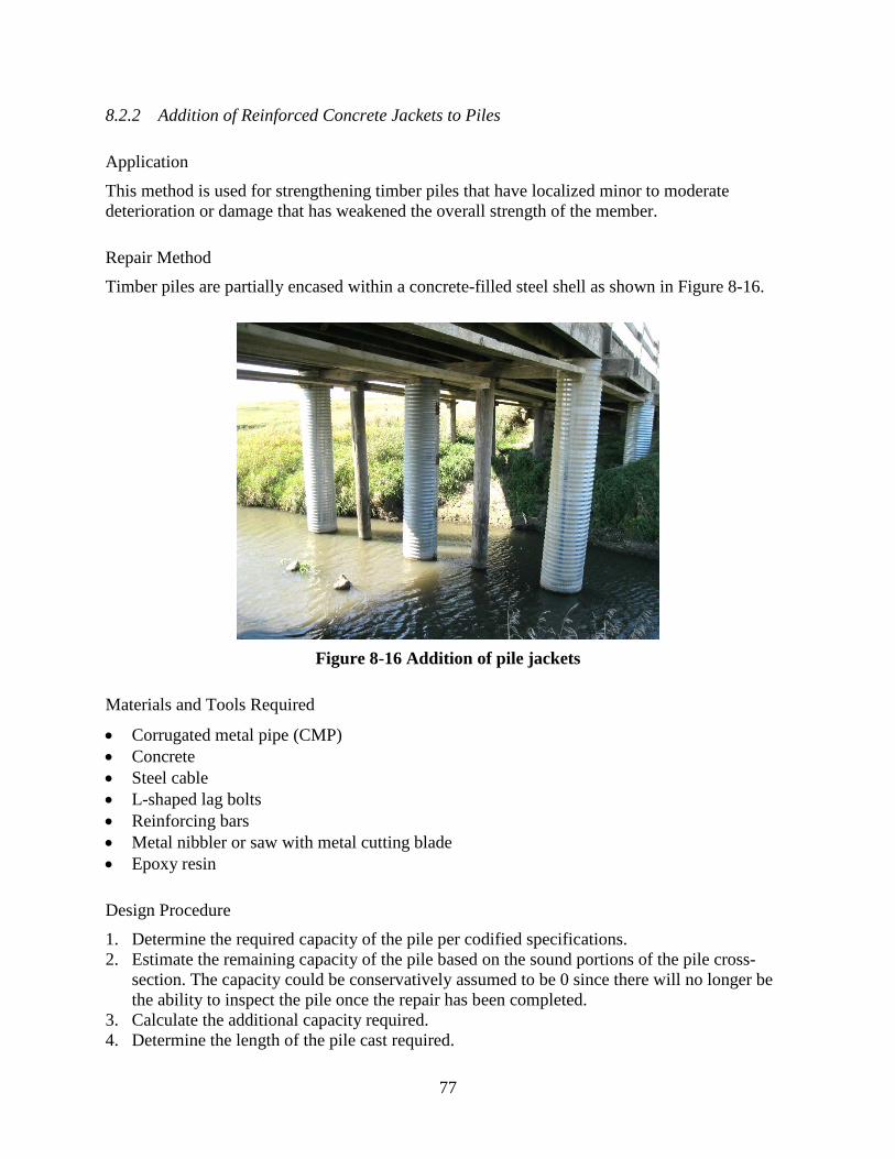
The primary objective of this work is to provide formal guidance to county engineers throughout Minnesota for repairing timber bridge components. The benefit of having such a resource will be measured by improving the overall condition of the transportation system and reducing system failures through implementation by local officials.
As is often the case, funds required to complete repairs are limited and, as a result, any method used must not only be structurally feasible but also economically feasible. This report provides bridge owners and caretakers several routine maintenance and repair options aimed to meet the goals of simplicity and affordability.
The economic impact of repairing timber bridges was assessed for multiple scenarios: a comparison was made between the net present value of repair at varying repair costs over time and the net present value of varying reconstruction costs over time. Through this exercise, for each scenario, a point in time was identified when repair or reconstruction makes most economic sense.
An additional assessment of overall costs (direct plus indirect) was completed, which included the increased user costs due to bridge posting or closure. This assessment made clear that when indirect costs are included, the benefits of maintaining or repairing a bridge to prevent posting or closure become great.
A standalone manual, Cost-Effective Timber Bridge Repairs: Manual for Repairs of Timber Bridges in Minnesota, was also developed for this project. 17. Document Analysis/Descriptors 18. Availability Statement Bridge management systems, Rehabilitation (Maintenance), Condition surveys, Direct costs, Economic analysis, Indirect costs, Wooden bridges, User charges
No restrictions. Document available from: National Technical Information Services, Alexandria, Virginia 22312
19. Security Class (this report) 20. Security Class (this page) 21. No. of Pages 22. Price Unclassified Unclassified 121
Development of Cost-Effective Timber Bridge Repair Techniques
for Minnesota
Final Report
Prepared by: Justin Dahlberg
Brent Phares Wayne Klaiber
Bridge Engineering Center and National Center for Wood Transportation Structures
Iowa State University
November 2015
Published by: Minnesota Department of Transportation
Research Services & Library 395 John Ireland Boulevard, MS 330
St. Paul, Minnesota 55155-1899
This report represents the results of research conducted by the authors and does not necessarily represent the views or policies of the Minnesota Department of Transportation and/or Iowa State University. This report does not contain a standard or specified technique.
The authors and the Minnesota Department of Transportation and Iowa State University do not endorse products or manufacturers. Any trade or manufacturers’ names that may appear herein do so solely because they are considered essential to this report.
Acknowledgments
Thank you to the following sponsors and project participants for their input into the development of this document.
Funding Sponsors Minnesota Local Road Research Board (LRRB) Iowa Highway Research Board (IHRB)
Project Team Bridge Engineering Center at Iowa State University Minnesota Department of Transportation Bridge Office Minnesota Department of Transportation Research Office Minnesota Local Road Research Board National Center for Wood Transportation Structures at Iowa State University Natural Resources Research Institute at the University of Minnesota Duluth USDA Forest Products Laboratory HDR Engineering, Inc.
Project Leaders Brian Brashaw - Natural Resources Research Institute at the University of Minnesota Duluth David Conkel - Minnesota Department of Transportation State Aid Travis Hosteng - National Center for Wood Transportation Structures at Iowa State University Chris Werner - HDR Engineering, Inc. James Wacker - USDA Forest Products Laboratory
Committee Members Ahmad Abu-Hawash - Iowa Department of Transportation Office of Bridges and Structures Matthew Hemmila - St. Louis County, Minnesota Greg Isakson - Goodhue County, Minnesota Art Johnston - USDA Forest Service, retired Brian Keierleber - Buchanan County, Iowa Mark Nahra - Woodbury County, Iowa Dan Warzala - Minnesota Department of Transportation Research Office John Welle - Aitkin County, Minnesota
Table of Contents
CHAPTER 1: GENERAL .............................................................................................................1
1.1 Introduction ................................................................................................................1 1.2 Research Objectives and Scope .................................................................................1 1.3 Report Content ...........................................................................................................1
CHAPTER 3: LITERATURE REVIEW .....................................................................................8
3.1 Repair of Timber Piles ...............................................................................................8 3.2 Repair of Timber Superstructures ............................................................................23 3.3 Repair of Timber Decks ...........................................................................................29
CHAPTER 4: COUNTY AND STATE SURVEYS ..................................................................31
4.1 Minnesota County Engineer Survey ........................................................................31 4.2 Iowa County Engineer Survey .................................................................................37 4.3 State Survey .............................................................................................................44
CHAPTER 5: MINNESOTA SITE VISITS ..............................................................................47
5.1 Aitkin County Site Visit Summary ..........................................................................47 5.2 St. Louis County Site Visit Summary ......................................................................49
CHAPTER 6: TYPES OF TYPICAL DETERIORATION .....................................................52
CHAPTER 8: BRIDGE STRENGTHENING AND REHABILITATION PROCEDURES ................................................................................................................66
8.1 Strengthening and Rehabilitation of Bridge Superstructure Elements ....................67 8.2 Strengthening and Rehabilitation of Bridge Substructure Elements .......................75
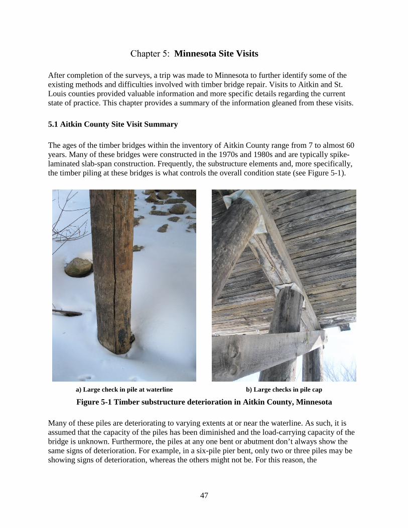
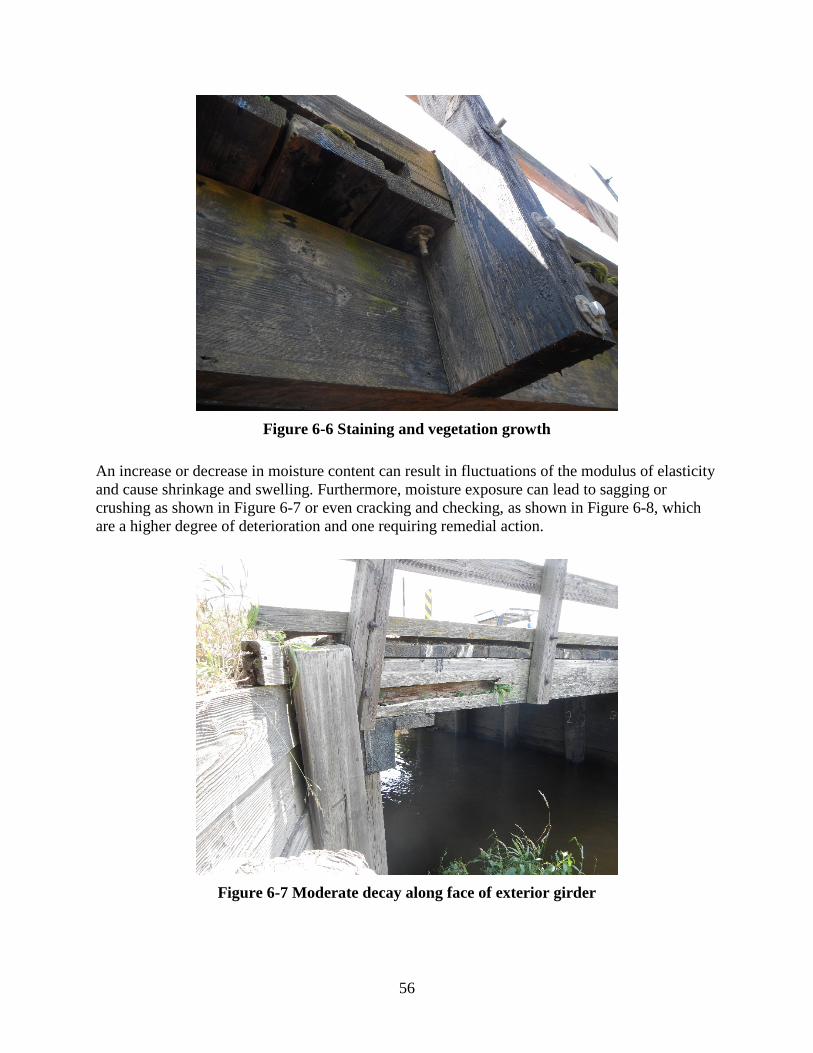
Figure 2-1 Typical timber slab bridge .............................................................................................4 Figure 2-2 Typical stringer/multi-beam or girder bridge .................................................................4 Figure 2-3 Condition rating descriptions .........................................................................................5 Figure 2-4 Condition ratings for slab and stringer bridges ..............................................................6 Figure 2-5 Cumulative distribution of condition ratings .................................................................7 Figure 3-1 Posting timber piles using concrete jacket or timber fishplates .....................................9 Figure 3-2 Posted piles using steel W shapes ..................................................................................9 Figure 3-3 Leveling mechanism for steel post on timber pile .......................................................10 Figure 3-4 Pile splice with steel pins and epoxy............................................................................11 Figure 3-5 Mechanical splice mechanical fasteners ......................................................................11 Figure 3-6 Pile splice using lapped joints and bolts ......................................................................12 Figure 3-7 Pile strengthened with steel sisters ...............................................................................13 Figure 3-8 Pile splice with FRP wraps ..........................................................................................14 Figure 3-9 Concrete jacketing with flexible and split fiberboard forms ........................................14 Figure 3-10 Concrete jacketing using corrugated metal pipe ........................................................15 Figure 3-11 Concrete jacketing with nylon sock ...........................................................................16 Figure 3-12 High-density polyethylene (HDPE) concrete jacket used at pile splice ....................16 Figure 3-13 Flexible PVC wrap .....................................................................................................17 Figure 3-14 Cross section of wood pile repaired with FRP composite shells ...............................18 Figure 3-15 Variations of FRP composite shells ...........................................................................18 Figure 3-16 FRP wrap filled with wood filler epoxy resin ............................................................19 Figure 3-17 Cross-sections of epoxy- and aggregate-repaired piles ..............................................20 Figure 3-18 Grout-filled timber pile with nail shear connectors ...................................................21 Figure 3-19 Timber planking and concrete encapsulation .............................................................22 Figure 3-20 Timber cap replacement at abutment and pier ...........................................................23 Figure 3-21 Repair of cracked or split stringers ............................................................................23 Figure 3-22 Timber cap scabs ........................................................................................................24 Figure 3-23 Stringer splice.............................................................................................................25 Figure 3-24 Girder or stringer replacement from below the deck .................................................25 Figure 3-25 Effects of fiber reinforcement adhered to bottom of timber beam .............................26 Figure 3-26 Plan view of vertically-oriented shear spike locations ...............................................27 Figure 3-27 Method of drilling for shear spike insertion ...............................................................27 Figure 3-28 Sprayed fiber-reinforced polymer ..............................................................................28 Figure 3-29 Shortening of span lengths .........................................................................................29 Figure 3-30 Local replacement of timber decking and added sheeting – plan view .....................30 Figure 3-31 Local replacement of timber decking and added sheeting – cross-section view .......30 Figure 5-1 Timber substructure deterioration in Aitkin County, Minnesota .................................47 Figure 5-2 Common timber pile issues in St. Louis County, Minnesota .......................................50 Figure 6-1 Timber deck without wearing surface in apparently good condition overall ...............52 Figure 6-2 Cracking of asphalt wearing surface ............................................................................53 Figure 6-3 Localized deck drainage through asphaltic wearing surface ........................................54 Figure 6-4 Deck debris accumulation at deck edge .......................................................................54 Figure 6-5 Stringer damaged by debris strike ................................................................................55 Figure 6-6 Staining and vegetation growth ....................................................................................56
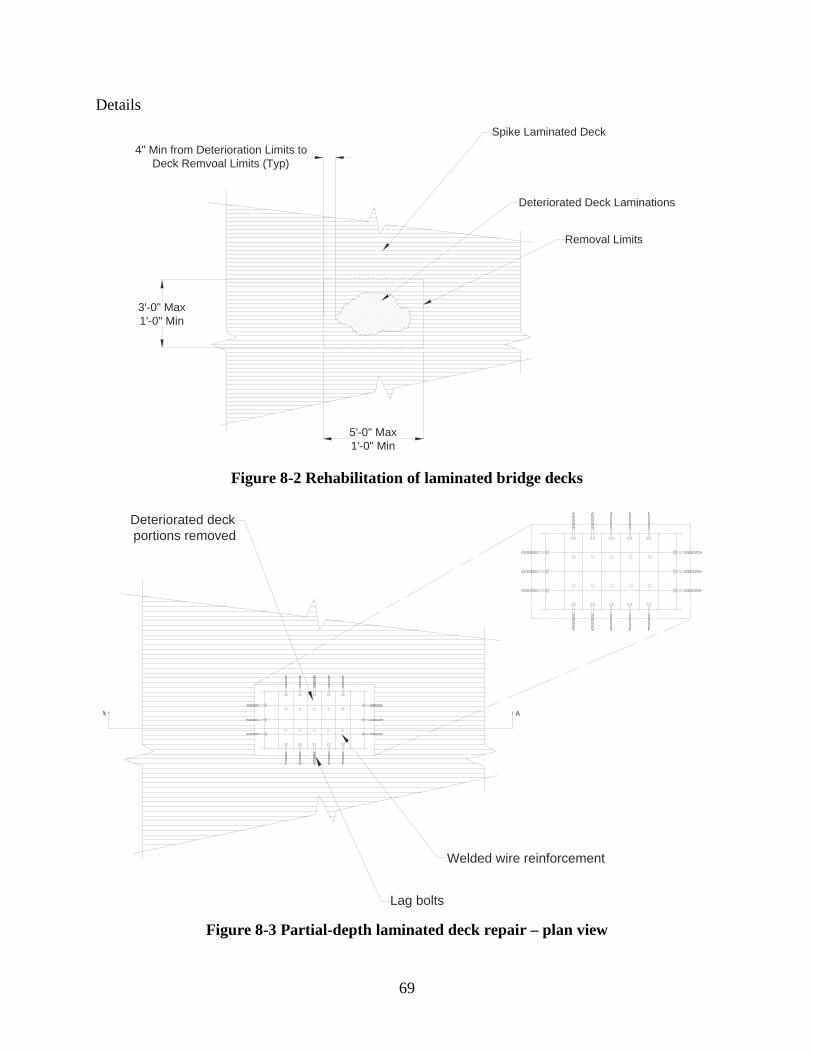
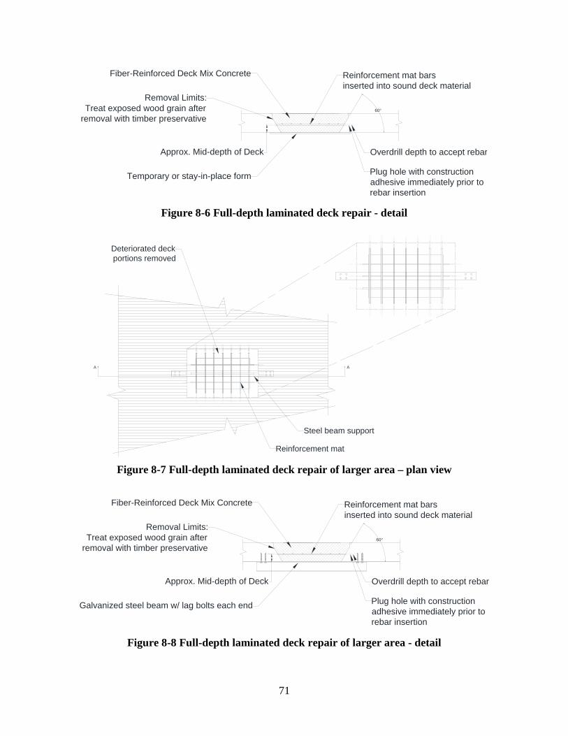
Figure 6-7 Moderate decay along face of exterior girder ..............................................................56 Figure 6-8 Checking at mid-depth of exterior girder .....................................................................57 Figure 6-9 Debris accumulation between stringer ends and pile cap ............................................57 Figure 6-10 Pile splitting at the waterline ......................................................................................58 Figure 6-11 Advanced decay at the ground surface .......................................................................59 Figure 6-12 Severely decayed timber piles at abutment ................................................................59 Figure 6-13 Advanced checking in pile cap ..................................................................................60 Figure 7-1 Concrete jacketing in CMP ..........................................................................................62 Figure 7-2 Pile encapsulation with timber planks and concrete ....................................................63 Figure 7-3 Sistered pile with channels and through bolts ..............................................................64 Figure 7-4 Localized deterioration and damage in laminated timber deck ...................................65 Figure 8-1 Repair of laminated decks ............................................................................................67 Figure 8-2 Rehabilitation of laminated bridge decks .....................................................................69 Figure 8-3 Partial-depth laminated deck repair – plan view ..........................................................69 Figure 8-4 Partial-depth laminated deck repair - detail .................................................................70 Figure 8-5 Full-depth laminated deck repair – plan view ..............................................................70 Figure 8-6 Full-depth laminated deck repair - detail .....................................................................71 Figure 8-7 Full-depth laminated deck repair of larger area – plan view .......................................71 Figure 8-8 Full-depth laminated deck repair of larger area - detail ...............................................71 Figure 8-9 Strengthening of individual timber stringers................................................................72 Figure 8-10 Strengthening of timber girder or stringer – shear reinforcement ..............................73 Figure 8-11 Strengthening of timber girder or stringer – flexural reinforcement, bottom
plate ....................................................................................................................................74 Figure 8-12 Strengthening of timber girder or stringer – flexural reinforcement, bottom
angle ...................................................................................................................................74 Figure 8-13 Strengthening of timber girder or stringer – flexural reinforcement, steel
channel ...............................................................................................................................74 Figure 8-14 Addition of steel sisters for pile reinforcement ..........................................................75 Figure 8-15 Addition of steel channels ..........................................................................................76 Figure 8-16 Addition of pile jackets ..............................................................................................77 Figure 8-17 Addition of concrete jacket ........................................................................................78 Figure 8-18 Pile encapsulation at abutment ...................................................................................79 Figure 8-19 Pile encapsulation – profile view ...............................................................................81 Figure 8-20 Pile encasement – section view ..................................................................................82 Figure 10-1 Minnesota timber bridge age distribution ..................................................................85 Figure 10-2 Example of $50,000 reconstruction cost versus $20,000 repair cost for an
average posted bridge ........................................................................................................87 Figure 10-3 Example of $50,000 reconstruction cost versus $20,000 repair cost for an
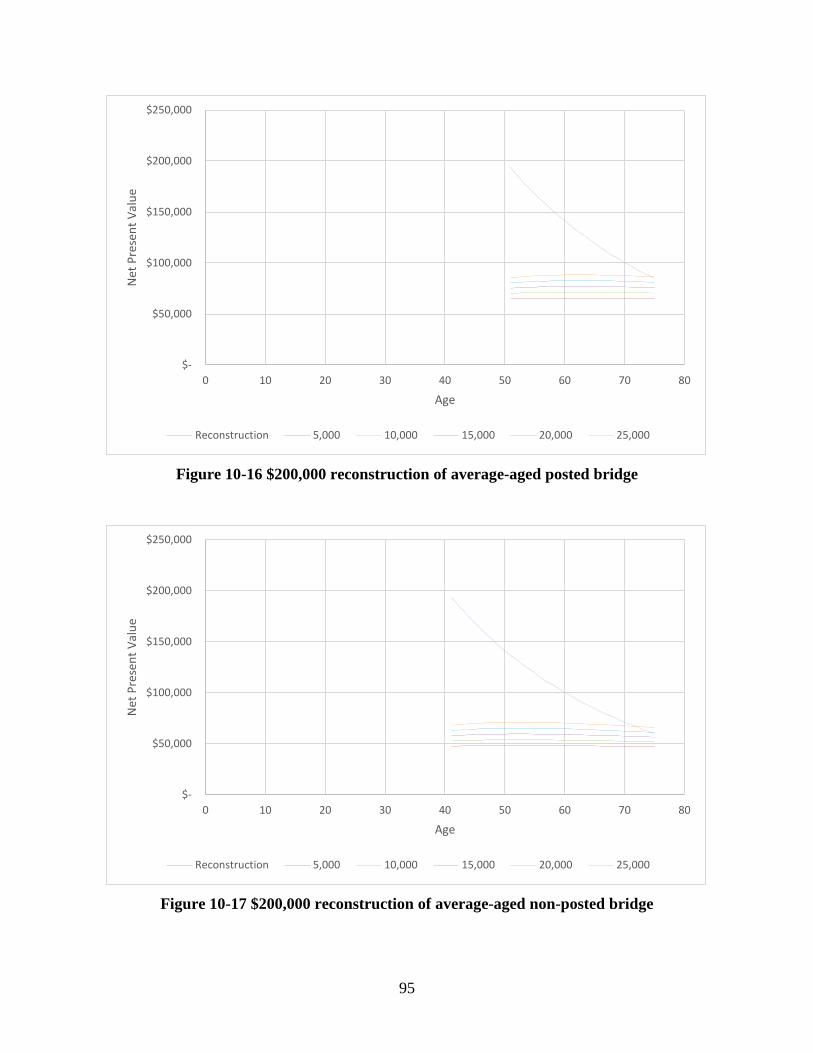
average non-posted bridge .................................................................................................88 Figure 10-4 $50,000 reconstruction of average-aged posted bridge..............................................89 Figure 10-5 $50,000 reconstruction of average-aged non-posted bridge ......................................89 Figure 10-6 $75,000 reconstruction of average-aged posted bridge..............................................90 Figure 10-7 $75,000 reconstruction of average-aged non-posted bridge ......................................90 Figure 10-8 $100,000 reconstruction of average-aged posted bridge............................................91 Figure 10-9 $100,000 reconstruction of average-aged non-posted bridge ....................................91 Figure 10-10 $125,000 reconstruction of average-aged posted bridge ..........................................92
Figure 10-11 $125,000 reconstruction of average-aged non-posted bridge ..................................92 Figure 10-12 $150,000 reconstruction of average-aged posted bridge ..........................................93 Figure 10-13 $150,000 reconstruction of average-aged non-posted bridge ..................................93 Figure 10-14 $175,000 reconstruction of average-aged posted bridge ..........................................94 Figure 10-15 $175,000 reconstruction of average-aged non-posted bridge ..................................94 Figure 10-16 $200,000 reconstruction of average-aged posted bridge ..........................................95 Figure 10-17 $200,000 reconstruction of average-aged non-posted bridge ..................................95 Figure 10-18 $225,000 reconstruction of average-aged posted bridge ..........................................96 Figure 10-19 $225,000 reconstruction of average-aged non-posted bridge ..................................96 Figure 10-20 $250,000 reconstruction of average-aged posted bridge ..........................................97 Figure 10-21 $250,000 reconstruction of average-aged non-posted bridge ..................................97 Figure 10-22 Truck operation costs due to detour for average-aged posted and non-posted
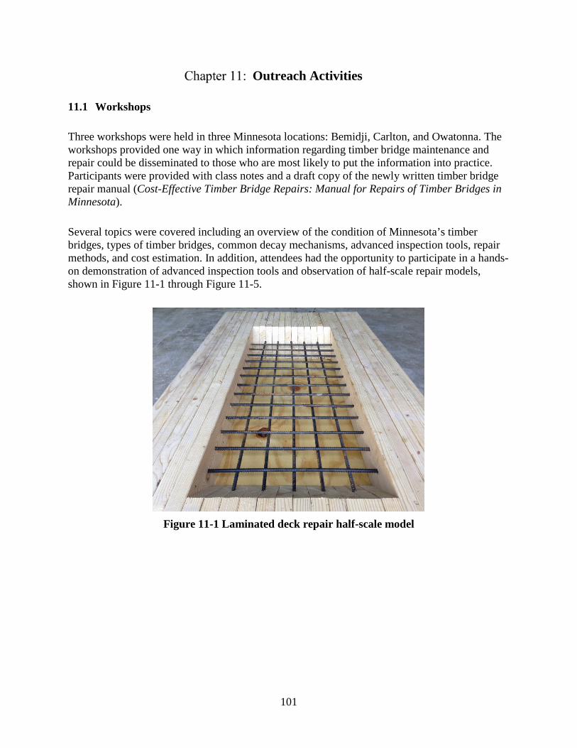
bridges ................................................................................................................................98 Figure 10-23 Non-posted bridge with repair completed ................................................................99 Figure 10-24 Non-posted bridge without repair ............................................................................99 Figure 10-25 Posted bridge with repair completed ........................................................................99 Figure 10-26 Posted bridge without repair ..................................................................................100 Figure 11-1 Laminated deck repair half-scale model ..................................................................101 Figure 11-2 Stringer sister half-scale model ................................................................................102 Figure 11-3 Pile channel reinforcement half-scale model ...........................................................102 Figure 11-4 Pile jacket half-scale model .....................................................................................103 Figure 11-5 Pile encapsulation half-scale model .........................................................................103
Few sources of comprehensive guidance for the repair of timber bridges are available to county engineers and others whose responsibilities include the management of timber bridge inventories. While numerous methods of repair are practiced across the US and other countries and even more research studies have been completed regarding timber repair, few documents exist that summarize the state of the practice and provide a complete document for practicing engineers. This creates a problem and a point of major concern for these individuals, and none more so than county engineers in Minnesota, as many have bridges in their inventories that are in need of repair.
As is often the case, funds required to complete repairs are limited and, as a result, any method used must not only be structurally feasible but also economically feasible. This report provides bridge owners and caretakers several routine maintenance and repair options aimed to meet the goals of simplicity and affordability.
To achieve the project goal of providing guidance for timber bridge maintenance and repair, the following general tasks were performed:
• Identification of current problems facing Minnesota timber bridge owners • Identification and development of promising methods of timber bridge repair • Study of the cost-effectiveness and economics of repair strategies and service life extensions
Several options for timber bridge repair are provided. Many of the repair options are presented at a conceptual level, while others (five total) are more fully developed. These include design and construction procedures, tools and equipment required, and cost estimates.
The five repairs were selected for extended development based on survey responses and on-site interviews, which indicated a need for these specific repairs, especially those that address substructure element repair.
Of the five repairs, each addresses one of the following timber bridge elements:
The economic impact of repairing timber bridges was assessed for multiple scenarios: a comparison was made between the net present value of repair at varying repair costs over time and the net present value of varying reconstruction costs over time. Through this exercise, for each scenario, a point in time was identified when repair or reconstruction makes most economic sense.
An additional assessment of overall costs (direct plus indirect), which included the increased user costs due to bridge posting or closure, was completed. This assessment made clear that when indirect costs are included, the benefits of maintaining or repairing a bridge to prevent posting or closure become great.
One of the primary objectives of this project was to produce a timber bridge repair manual. The manual, Cost-Effective Timber Bridge Repairs: Manual for Repairs of Timber Bridges in Minnesota, is comprised of some of the content within this report along with an extended presentation of timber maintenance options. The final manual is a standalone document from which the maintenance and repair options can be implemented.
Efforts to distribute information to those who are most likely to implement the repair options were completed using a three-fold approach including workshops, webinars, and a pre-recorded presentation to be offered as part of annual bridge training. Collectively, these outreach efforts reached numerous people throughout Minnesota from both public and private agencies.
1
General
1.1 Introduction
Few sources of comprehensive guidance for the repair of timber bridges are available to county engineers and others whose responsibilities include the management of timber bridge inventories. While numerous methods of repair are practiced across the US and other countries and even more research studies have been completed regarding timber repair, few documents exist that summarize the state of the practice and provide a complete document for practicing engineers. This creates a problem and a point of major concern for these individuals, and none more so than county engineers in Minnesota, as many have bridges in their inventories that are in need of repair.
As is often the case, funds required to complete repairs are limited and, as a result, any method used must not only be structurally feasible but also economically feasible. The repair options identified in this report provide an overview of available repair options but also aim to meet the goals for simple, affordable solutions.
1.2 Research Objectives and Scope
The primary objective of this work is to provide formal guidance to county engineers throughout Minnesota for repairing timber bridge components. The benefit of having such a resource will be measured by improving the overall condition of the transportation system and reducing system failures through implementation by local officials.
The scope of the project can be described by five main foci: 1) identify repair strategies that will be effective for Minnesota’s timber bridge population, 2) study the cost-effectiveness and economics of repair strategies and extension of service life, 3) develop a timber bridge repair manual, 4) conduct outreach, and 5) produce final report for the project.
1.3 Report Content
The remainder of this report is organized as follows: Chapter 2 describes the timber bridge types most commonly found in Minnesota. Chapter 3 provides summaries of pertinent information from the literature review of numerous resources. Chapter 4 presents the results of county and state surveys regarding the state of the practice of timber bridge repair. Chapter 5 provides a summary of on-site visits with Minnesota county engineers. Chapter 6 discusses and summarizes the specific issues or types of deterioration commonly seen among Minnesota’s timber bridge inventory. Chapter 7 highlights repair solutions that the researchers consider to be effective or the most promising for Minnesota after careful evaluation of techniques from a structural and economic standpoint. Chapter 8 presents instructional details and drawings for five strengthening and rehabilitating procedures that were developed to address the timber bridge concerns in Minnesota (which were identified through survey questionnaire results and interaction with county engineers). Cost estimates for each of the procedures presented in Chapter 8 are included
2
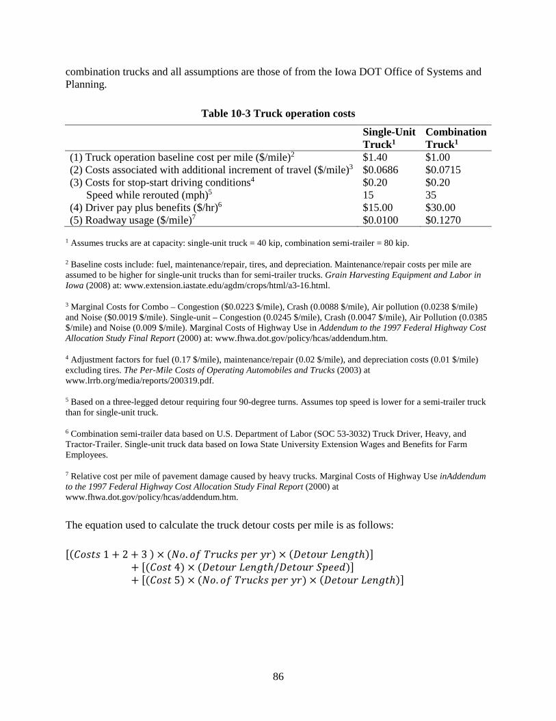
in Chapter 9. The economic impact of repairing timber bridges was assessed for multiple scenarios along with an assessment of overall costs (direct plus indirect), which included the increased user costs due to bridge posting or closure, and this information is presented in Chapter 10. Chapter 11 briefly covers the outreach activities (workshops, webinars, and a pre-recorded presentation for annual bridge training) that were part of this project. Chapter 12 provides conclusions, which are followed by the References.
3
Minnesota Timber Bridges
The variety of timber bridge structure types is extensive at the national level and, as shown in Table 2-1, even within Minnesota, numerous types of timber bridges exist including the following: 1) slab, 2) stringer/multi-beam or girder, 3) girder and floorbeam system, 4) truss – thru, 5) arch – deck, and 6) culverts.
Type # Slab 1,081 Stringer/Multi-Beam or Girder 395 Girder and Floorbeam System 2 Truss – Thru 2 Arch – Deck 1 Culvert (includes frame culverts) 22
Source: 2012 National Bridge Inventory downloaded from the FHWA May 2013
According to the 2012 National Bridge Inventory (downloaded from the Federal Highway Administration/FHWA May 2013), these bridges make up a total of 1,503 bridges at the county level; a majority of the bridges, 1,476, are slab or stringer/multi-beam (1,081) or girder (395). Given that a significant portion of the population lies within these two types, it is here where much of the information provided and discussed within this report is focused. For the sake of brevity, we’ll refer to these as slab and stringer bridges in this report.
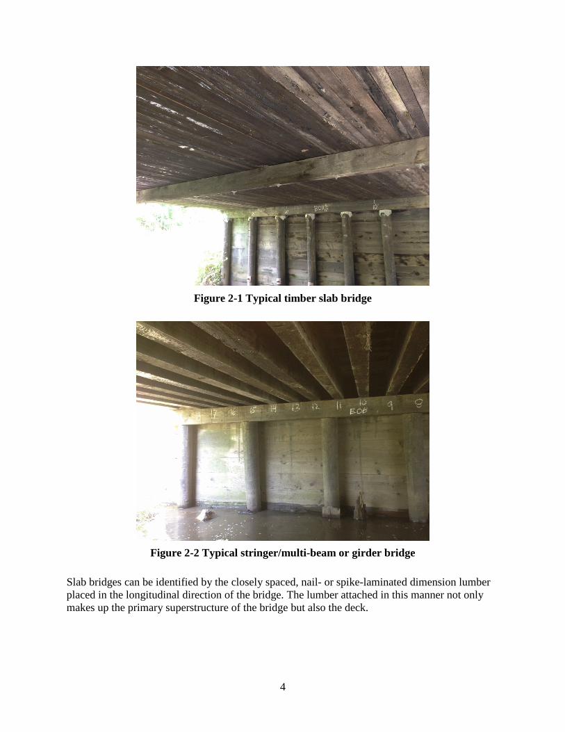
Figure 2-1 and Figure 2-2 show a typical slab bridge and stringer bridge, respectively.
4
Figure 2-1 Typical timber slab bridge
Figure 2-2 Typical stringer/multi-beam or girder bridge
Slab bridges can be identified by the closely spaced, nail- or spike-laminated dimension lumber placed in the longitudinal direction of the bridge. The lumber attached in this manner not only makes up the primary superstructure of the bridge but also the deck.
5
Stringer bridges can be identified by the full-sawn timber (sometimes glued-laminated/glulam) stringers or girders placed in the longitudinal direction of the bridge with a transverse timber deck laid and attached to the top of the stringers.
In both cases, the substructure construction most often consists of full-sawn timber pile caps on timber piles at abutment and pier locations; the slab or stringers generally lie directly on the pile caps. At the abutment locations, it is often timber backwalls that retain the soil and approaching roadway.
Within the National Bridge Inventory, the condition of a bridge is described by its three major components: deck, superstructure, and substructure. A condition rating, 0 through 9 or N if not applicable, is assigned to each component based on its condition when inspected. Each rating is described in the Recording and Coding Guide for the Structure Inventory and Appraisal of the Nation’s Bridges (FHWA 1995) as is shown in Figure 2-3.
FHWA 1995
Figure 2-3 Condition rating descriptions
The distribution of the condition ratings for deck, superstructure, and substructure among the slab and stringer bridges (1,476 total) is shown in Figure 2-4.
6
0
50
100
150
200
250
300
350
400
450
N 9 8 7 6 5 4 3 2 1 0
Num
ber o
f Brid
ges
Condition Rating
Deck Superstructure Substructure
Figure 2-4 Condition ratings for slab and stringer bridges
At first glance, it would appear that the bridges are in relatively good condition overall given that the distribution tends to peak around a condition rating of 7 or Good Condition. At closer look, however, note the number of bridges that are considered only in Fair (rating of 5) or worse condition. Figure 2-5 provides the cumulative distribution for each of the bridge elements that fall into or below any given condition rating.
7
0%
20%
40%
60%
80%
100%
120%
9 8 7 6 5 4 3 2 1 0
Cum
ulat
ive
Perc
enta
ge
Condition Rating
Deck Superstructure Substructure
Figure 2-5 Cumulative distribution of condition ratings
For example, 32.1 percent of all slab and stringer timber bridge substructures are considered Fair or worse. Worse yet, 17.6 percent are considered to be in Poor or worse condition. That is to say that, at best, nearly 20 percent of the substructures have advanced section loss, deterioration, spalling, or scour.
Although the deck and superstructure condition ratings tend to be better than that of the substructures, there are still a significant number that require remedial attention. The National Bridge Inventory data largely confirms what the county engineers stated within the administered surveys (presented later in this report) as the substructure being the bridge element with the biggest need for corrective action.
8
Literature Review
With the condition of timber bridges in Minnesota in mind, the researchers completed a literature review that identified the state of the practice for timber bridge repair in the US and other countries that are known to have a large number of timber bridges. To complete the review, information was sought from numerous sources including those obtained from enlisting common search engines, previously conducted research, and personal queries. This chapter summarizes the findings of the literature review.
3.1 Repair of Timber Piles
3.1.1 Posting/Splicing
The method of posting and splicing is most often performed above the ground line where accessibility to the pile is possible without too much difficulty. Be that as it may, the method can be performed below the ground line when the extents of the deteriorated portion warrant doing so.
This method is described in research conducted by White et al. 2007. To complete the repair, after the pile cap is temporarily supported with a strut and jack or other means, the deteriorated portion is cut out of the pile and replaced with a section similar in diameter. Cuts are made above and below the section to be removed. Once removed, the new treated pile portion can be installed. Attachment to the remaining portions of the pile can be achieved through various methods including timber fishplates and concrete jacketing. Figure 3-1 schematically shows examples of both methods. If timber fishplates are used, they must be treated and all fasteners must be galvanized. Additional discussion of the concrete jacketing method is included later in this document.
9
New pilesection
Concrete jacketOriginalpile
Metalfastener
Timberfishplates
Galvanizedbolts
Steelplates
Hydrauliclift
Timber strut
Post cutto fit
(a) Concrete jacket (b) Timber fishplates
Ground level
White et al. 2007
Figure 3-1 Posting timber piles using concrete jacket or timber fishplates
A method of posting used in Iowa is shown in Figure 3-2 (Dahlberg et al. 2012).
Dahlberg et al. 2012
Figure 3-2 Posted piles using steel W shapes
10
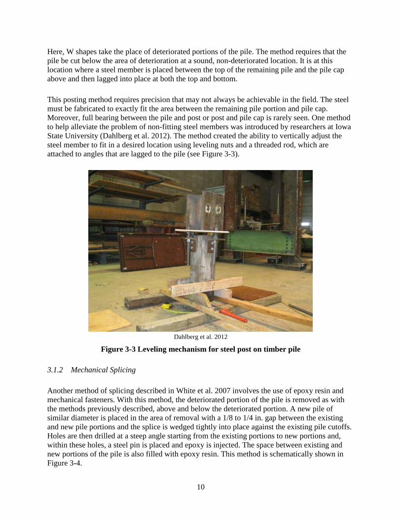
Here, W shapes take the place of deteriorated portions of the pile. The method requires that the pile be cut below the area of deterioration at a sound, non-deteriorated location. It is at this location where a steel member is placed between the top of the remaining pile and the pile cap above and then lagged into place at both the top and bottom.
This posting method requires precision that may not always be achievable in the field. The steel must be fabricated to exactly fit the area between the remaining pile portion and pile cap. Moreover, full bearing between the pile and post or post and pile cap is rarely seen. One method to help alleviate the problem of non-fitting steel members was introduced by researchers at Iowa State University (Dahlberg et al. 2012). The method created the ability to vertically adjust the steel member to fit in a desired location using leveling nuts and a threaded rod, which are attached to angles that are lagged to the pile (see Figure 3-3).
Dahlberg et al. 2012
Figure 3-3 Leveling mechanism for steel post on timber pile
3.1.2 Mechanical Splicing
Another method of splicing described in White et al. 2007 involves the use of epoxy resin and mechanical fasteners. With this method, the deteriorated portion of the pile is removed as with the methods previously described, above and below the deteriorated portion. A new pile of similar diameter is placed in the area of removal with a 1/8 to 1/4 in. gap between the existing and new pile portions and the splice is wedged tightly into place against the existing pile cutoffs. Holes are then drilled at a steep angle starting from the existing portions to new portions and, within these holes, a steel pin is placed and epoxy is injected. The space between existing and new portions of the pile is also filled with epoxy resin. This method is schematically shown in Figure 3-4.
11
Replacementsection
Injectionports
Wedge
Hole for epoxyand steel pins
Joint
Steel pins
Existing pile
Section at splice
Wedge
Washer and nails
Holes were steelpins intersectpile cut-off
White et al. 2007
Figure 3-4 Pile splice with steel pins and epoxy
Laboratory and field testing showed that the original ultimate compressive strength and axial stiffness of deteriorated piles is economically and effectively restored using this method. However, the ultimate flexural strength was reduced by 50 to 75 percent (White et al. 2007). As such, it is recommended that this method be used when only a few piles are in need of repair.
Similarly, a study was conducted at Iowa State University that investigated another splicing type repair method (White et al. 2007). The method utilized lap splices mechanically fastened with long lag screws. Along with control sections, tests were conducted on the posted specimens to measure the ultimate capacity in compression and bending. Both the new and existing portions of the pile were cut so that each could lap the other. The tests revealed that about 70 percent of the axial capacity of the original pile was restored, while only 20 percent of the bending capacity was restored. This method is shown in Figure 3-5.
Newsection
1'
3"
1'
2'-3"
White et al. 2007
Figure 3-5 Mechanical splice mechanical fasteners
12
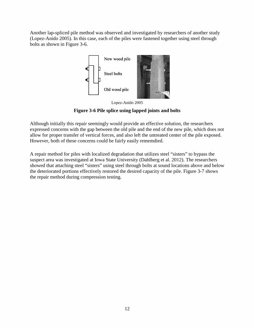
Another lap-spliced pile method was observed and investigated by researchers of another study (Lopez-Anido 2005). In this case, each of the piles were fastened together using steel through bolts as shown in Figure 3-6.
Lopez-Anido 2005
Figure 3-6 Pile splice using lapped joints and bolts
Although initially this repair seemingly would provide an effective solution, the researchers expressed concerns with the gap between the old pile and the end of the new pile, which does not allow for proper transfer of vertical forces, and also left the untreated center of the pile exposed. However, both of these concerns could be fairly easily rememdied.
A repair method for piles with localized degradation that utilizes steel “sisters” to bypass the suspect area was investigated at Iowa State University (Dahlberg et al. 2012). The researchers showed that attaching steel “sisters” using steel through bolts at sound locations above and below the deteriorated portions effectively restored the desired capacity of the pile. Figure 3-7 shows the repair method during compression testing.
13
Dahlberg et al. 2012
Figure 3-7 Pile strengthened with steel sisters
3.1.3 Splice with FRP Wrap
Another study completed by Iowa State University explored the option of splicing a timber pile using fiber-reinforced polymer (FRP) wrapping (White et al. 2007). In this study, the deteriorated portion of the pile was removed and replaced with a sound pile portion of similar size. Afterwards, multiple FRP wraps coated with epoxy resin were used to join the two portions of the pile with the wraps overlapping the sawn joint by approximately 7 in. Axial and bending tests showed that the repair restored nearly 100 percent of the axial capacity, while only approximately 50 percent of the bending capacity was restored. This repair is shown in Figure 3-8.
14
Newsection
1'
1'
2'
1'
FRP shell
2'-6"
White et al. 2007
Figure 3-8 Pile splice with FRP wraps
3.1.4 Concrete Jacketing
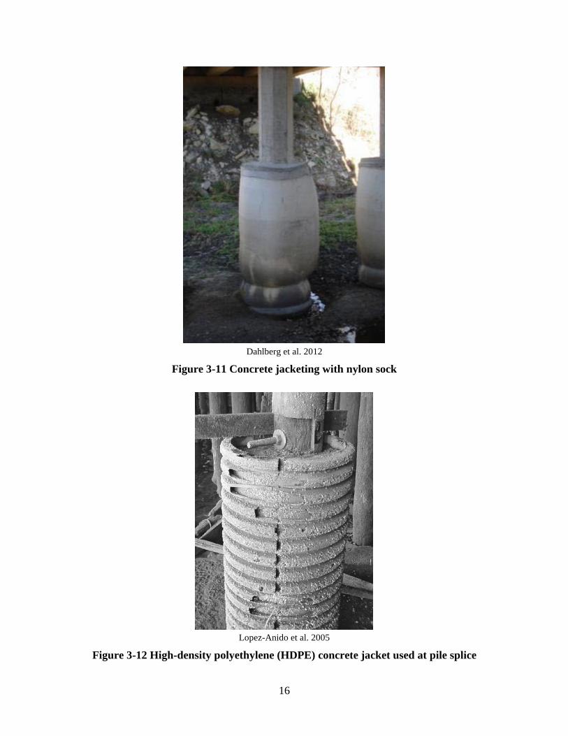
Concrete jacketing has been a method employed in various fashions on timber, steel, or concrete piles over the past decades. The method is largely effective in restoring the desired capacity to a deteriorated pile and provides a relatively cost-effective method of repair. The method uses a jacket, which can take on many forms (e.g., corrugated metal pipe, flexible forms, split fiberboard forms), which are essentially wrapped around the length of the deteriorated area. A reinforcing cage is often but not always included within the form and around the pile. In either case, the form is filled with concrete creating a cast around the deteriorated pile. Examples of the varying forms of concrete jacketing are shown in Figure 3-9 through Figure 3-12.
US Army Corps of Engineers 2001
Figure 3-9 Concrete jacketing with flexible and split fiberboard forms
15
Dahlberg et al. 2012
Figure 3-10 Concrete jacketing using corrugated metal pipe
16
Dahlberg et al. 2012
Figure 3-11 Concrete jacketing with nylon sock
Lopez-Anido et al. 2005
Figure 3-12 High-density polyethylene (HDPE) concrete jacket used at pile splice
17
3.1.5 Polyvinyl Chloride Wrap
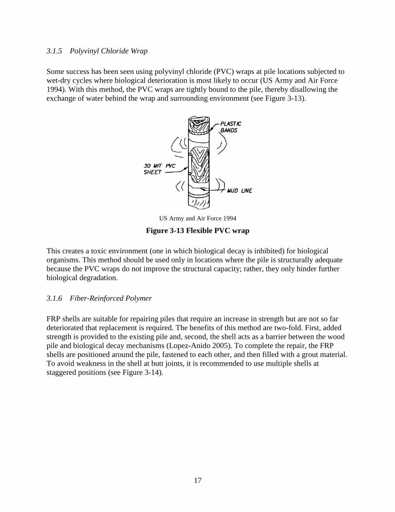
Some success has been seen using polyvinyl chloride (PVC) wraps at pile locations subjected to wet-dry cycles where biological deterioration is most likely to occur (US Army and Air Force 1994). With this method, the PVC wraps are tightly bound to the pile, thereby disallowing the exchange of water behind the wrap and surrounding environment (see Figure 3-13).
US Army and Air Force 1994
Figure 3-13 Flexible PVC wrap
This creates a toxic environment (one in which biological decay is inhibited) for biological organisms. This method should be used only in locations where the pile is structurally adequate because the PVC wraps do not improve the structural capacity; rather, they only hinder further biological degradation.
3.1.6 Fiber-Reinforced Polymer
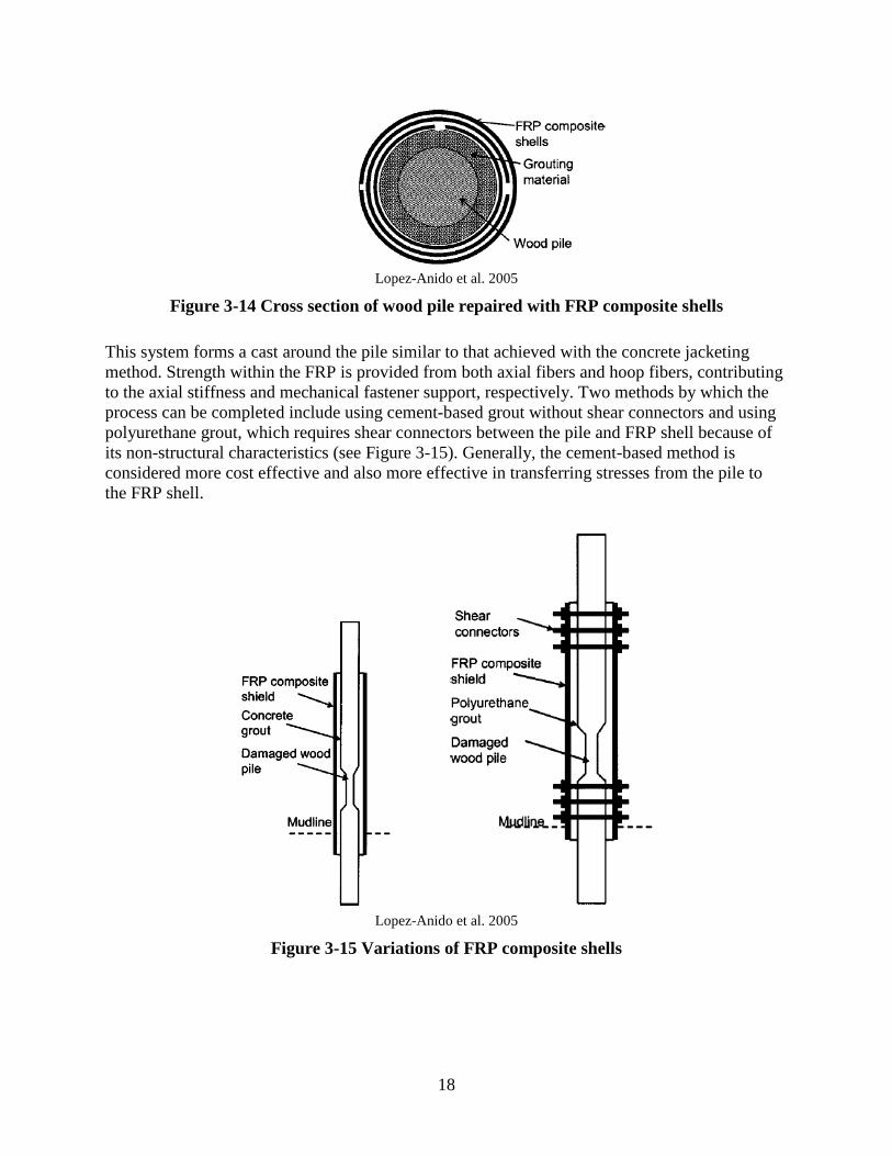
FRP shells are suitable for repairing piles that require an increase in strength but are not so far deteriorated that replacement is required. The benefits of this method are two-fold. First, added strength is provided to the existing pile and, second, the shell acts as a barrier between the wood pile and biological decay mechanisms (Lopez-Anido 2005). To complete the repair, the FRP shells are positioned around the pile, fastened to each other, and then filled with a grout material. To avoid weakness in the shell at butt joints, it is recommended to use multiple shells at staggered positions (see Figure 3-14).
18
Lopez-Anido et al. 2005
Figure 3-14 Cross section of wood pile repaired with FRP composite shells
This system forms a cast around the pile similar to that achieved with the concrete jacketing method. Strength within the FRP is provided from both axial fibers and hoop fibers, contributing to the axial stiffness and mechanical fastener support, respectively. Two methods by which the process can be completed include using cement-based grout without shear connectors and using polyurethane grout, which requires shear connectors between the pile and FRP shell because of its non-structural characteristics (see Figure 3-15). Generally, the cement-based method is considered more cost effective and also more effective in transferring stresses from the pile to the FRP shell.
Lopez-Anido et al. 2005
Figure 3-15 Variations of FRP composite shells
19
Variations of the FRP shell method have been produced by at least two companies: Hardcore Composites of New Castle, Delaware, which developed the Hardshell System, and Fibrwrap Construction. The Hardshell System uses composite shells constructed around the pile in two halves and joined with connectors at the seam. The strength of a single point of connection at the seams is of some concern. Fibrwrap uses a fabric reinforcement, which is wrapped around the timber pile and then impregnated with epoxy resin. The curing of the resin is of some concern if the wrap is submerged below the waterline.
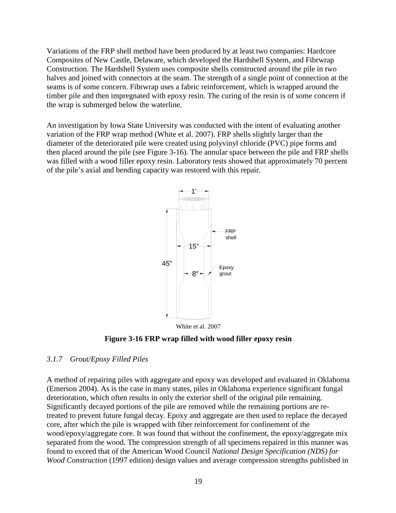
An investigation by Iowa State University was conducted with the intent of evaluating another variation of the FRP wrap method (White et al. 2007). FRP shells slightly larger than the diameter of the deteriorated pile were created using polyvinyl chloride (PVC) pipe forms and then placed around the pile (see Figure 3-16). The annular space between the pile and FRP shells was filled with a wood filler epoxy resin. Laboratory tests showed that approximately 70 percent of the pile’s axial and bending capacity was restored with this repair.
1'
FRPshell
15"
8"Epoxygrout
45"
White et al. 2007
Figure 3-16 FRP wrap filled with wood filler epoxy resin
3.1.7 Grout/Epoxy Filled Piles
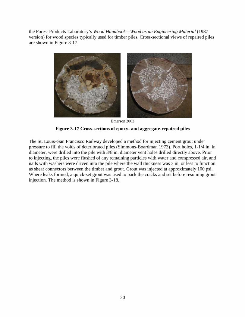
A method of repairing piles with aggregate and epoxy was developed and evaluated in Oklahoma (Emerson 2004). As is the case in many states, piles in Oklahoma experience significant fungal deterioration, which often results in only the exterior shell of the original pile remaining. Significantly decayed portions of the pile are removed while the remaining portions are re-treated to prevent future fungal decay. Epoxy and aggregate are then used to replace the decayed core, after which the pile is wrapped with fiber reinforcement for confinement of the wood/epoxy/aggregate core. It was found that without the confinement, the epoxy/aggregate mix separated from the wood. The compression strength of all specimens repaired in this manner was found to exceed that of the American Wood Council National Design Specification (NDS) for Wood Construction (1997 edition) design values and average compression strengths published in
20
the Forest Products Laboratory’s Wood Handbook—Wood as an Engineering Material (1987 version) for wood species typically used for timber piles. Cross-sectional views of repaired piles are shown in Figure 3-17.
Emerson 2002
Figure 3-17 Cross-sections of epoxy- and aggregate-repaired piles
The St. Louis–San Francisco Railway developed a method for injecting cement grout under pressure to fill the voids of deteriorated piles (Simmons-Boardman 1973). Port holes, 1-1/4 in. in diameter, were drilled into the pile with 3/8 in. diameter vent holes drilled directly above. Prior to injecting, the piles were flushed of any remaining particles with water and compressed air, and nails with washers were driven into the pile where the wall thickness was 3 in. or less to function as shear connectors between the timber and grout. Grout was injected at approximately 100 psi. Where leaks formed, a quick-set grout was used to pack the cracks and set before resuming grout injection. The method is shown in Figure 3-18.
21
Simmons-Boardman 1973
Figure 3-18 Grout-filled timber pile with nail shear connectors
3.1.8 Pile Encapsulation
Pile encapsulation is a method of pile repair and strengthening that has been used occasionally in Iowa and likely other locations as well, although this was not confirmed in Dahlberg et al. 2012. This method can be simply and effectively used at abutment and pier locations if the piles are of similar size and in relatively good alignment with each other. Multiple timber planks are fastened to each face of the piles at pier locations and on the span-side face at abutment locations. The planks form a crib that contains cast-in-place concrete between each of the piles (see Figure 3-19).
22
Dahlberg et al. 2012
Figure 3-19 Timber planking and concrete encapsulation
The concrete encapsulates the portions of the pile for which planking has been installed. The planking and concrete provide additional stiffness to the pile group given that the effective length of each pile is reduced and the piles are tied together.
3.1.9 Timber Cap Replacement
When timber caps deteriorate to a point that replacement is necessary, the superstructure must be jacked-up so that access to and removal of the old cap can be achieved (Johnson 2002). This method can be accomplished by using timber cribbing as a jack stand and a false cap for the stringers to bear on as shown in Figure 3-20.
23
Johnson 2002
Figure 3-20 Timber cap replacement at abutment and pier
Once the superstructure has been raised 1 to 2 in., the old cap can be cut out and removed, and the new cap can be moved into position. Lowering the jacks and then fastening the stringers and existing piling to the new cap with steel straps and drift pins complete the repair.
3.2 Repair of Timber Superstructures
3.2.1 Scabbing or Splicing
When timber deteriorates to a point that the structural integrity of the member is questionable, one method that can restore the strength of the member is to scab additional lumber or steel plates to the member (US Army and Air Force 1994). This method effectively provides a path for loads to bypass the deteriorated portion. Note that this method is intended only for when a member has deteriorated no further than a moderate level though. This method could be ineffective and another method such as splicing might be more suitable for members with extensive deterioration. Figure 3-21 and Figure 3-22 show examples of two scabbing methods.
US Army and Air Force 1994
Figure 3-21 Repair of cracked or split stringers
24
US Army and Air Force 1994
Figure 3-22 Timber cap scabs
The first (Figure 3-21) is for the reinforcement of a timber girder or stringer. Steel plates are attached to the stringer and deck system via draw-up bolts, which strengthen the damaged area by closing slits and cracks in the member and by developing composite action between the stringer and the deck.
The second (Figure 3-22) is more commonly used on a timber cap to extend the bearing area of timber stringers and girders where the ends have deteriorated to a point where the bearing capacity has been reduced.
Contrary to scabbing, splicing is a method used when the timber has been severely damaged or has seen significant deterioration (US Army and Air Force 1994). The method is similar to scabbing other than the deteriorated portion of the member is removed and replaced. Supplemental members are added to either side of the original member and connected with through bolts. An example of splicing is shown in Figure 3-23.
25
US Army and Air Force 1994
Figure 3-23 Stringer splice
3.2.2 Replacement of Flexural Timber Components
Occasionally, a timber girder or stringer is beyond repair and requires replacement. This can be achieved from below the deck by jacking the deck from the pile cap on each side and at each end of the respective stringer (US Army and Air Force 1994). The original stringer is removed and a new stringer is put in its place after it has been cut as needed to allow for insertion. The jacks are then removed and the ends of the stringer are wedged so that contact with the deck is made along its length. The method is schematically shown in Figure 3-24.
US Army and Air Force 1994
Figure 3-24 Girder or stringer replacement from below the deck
26
3.2.3 Carbon Fiber and Glass Fiber Reinforcement
A study completed by Johns and Lacroix (2000) showed that sawn timber beams can be reinforced using high-performance composite materials, carbon and glass fibers. In this case, the materials were adhered with epoxy resin to the bottom of the stringers or girders, two-layers thick, having an effective width and depth of 28 mm and 0.165 mm, respectively. Figure 3-25 shows the results from 25-member sample sets before (left) and after (right) reinforcing. Although a relatively small sample, it could be surmised from the shift in the histogram that the reinforcement provided an appreciable increase in bending capacity.
Figure 3-25 Effects of fiber reinforcement adhered to bottom of timber beam
3.2.4 Fiber-Reinforced Polymer Spikes
Studies have been completed investigating the effects of adding vertically-oriented shear spikes with fiberglass-reinforced polymer rods (Burgers et al. 2005). These studies have shown that the spikes increase the effective stiffness of timber stringers. The placement of the shear spikes into pre-drilled holes along the top of the beam is shown in Figure 3-26.
27
Burgers et al. 2005
Figure 3-26 Plan view of vertically-oriented shear spike locations
Holes are created by first drilling a pilot before proceeding with a larger-sized bit and finally augering the first several inches for ease of insertion (see Figure 3-27).
Burgers et al. 2005
Figure 3-27 Method of drilling for shear spike insertion
The spikes, along with epoxy resin, are inserted into the holes in pairs nearly the full depth of the beam. The shear spikes are intended to improve the interlayer shear resistance by reconnecting the sound wood throughout the beam depth. For example, if a severe longitudinal check is present in a timber girder, spikes inserted through layers above and below the check effectively “nail” the two portions together.
28
3.2.5 Sprayed Fiber-Reinforced Polymer
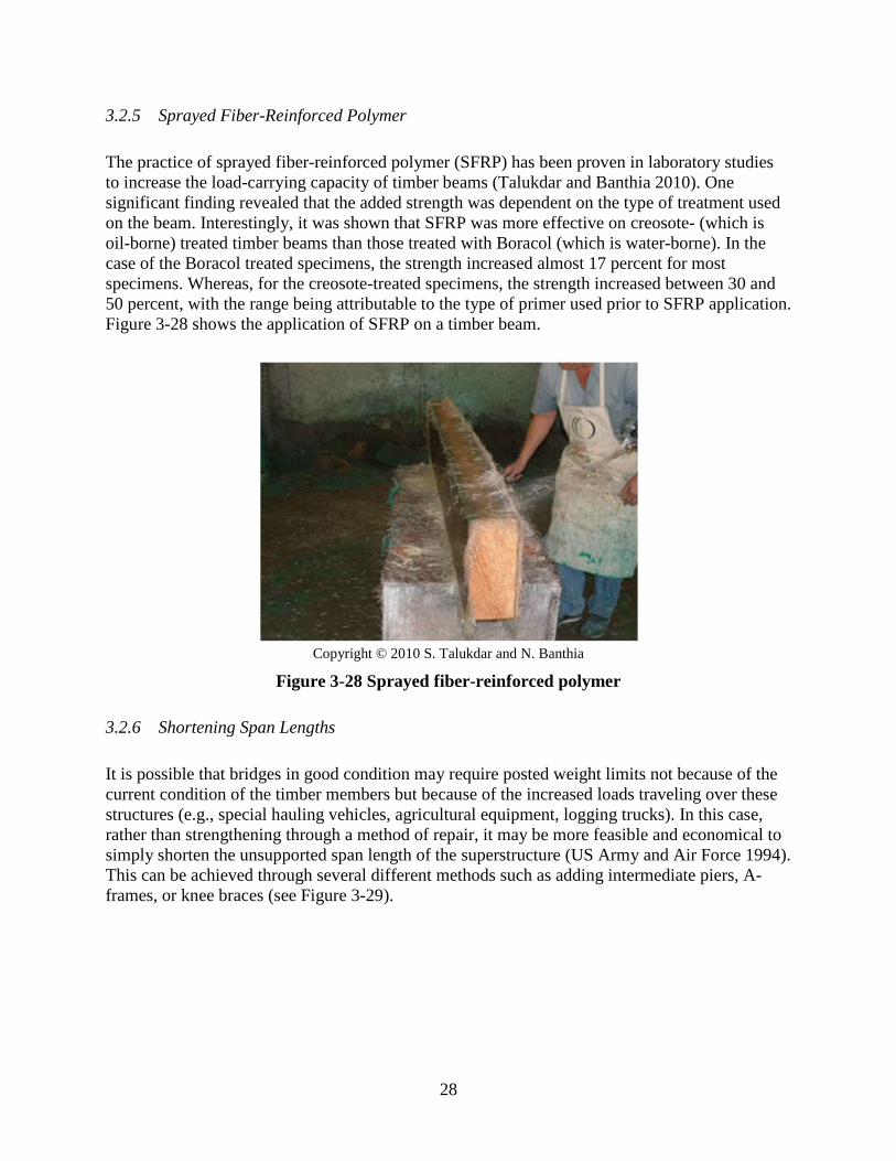
The practice of sprayed fiber-reinforced polymer (SFRP) has been proven in laboratory studies to increase the load-carrying capacity of timber beams (Talukdar and Banthia 2010). One significant finding revealed that the added strength was dependent on the type of treatment used on the beam. Interestingly, it was shown that SFRP was more effective on creosote- (which is oil-borne) treated timber beams than those treated with Boracol (which is water-borne). In the case of the Boracol treated specimens, the strength increased almost 17 percent for most specimens. Whereas, for the creosote-treated specimens, the strength increased between 30 and 50 percent, with the range being attributable to the type of primer used prior to SFRP application. Figure 3-28 shows the application of SFRP on a timber beam.
It is possible that bridges in good condition may require posted weight limits not because of the current condition of the timber members but because of the increased loads traveling over these structures (e.g., special hauling vehicles, agricultural equipment, logging trucks). In this case, rather than strengthening through a method of repair, it may be more feasible and economical to simply shorten the unsupported span length of the superstructure (US Army and Air Force 1994). This can be achieved through several different methods such as adding intermediate piers, A-frames, or knee braces (see Figure 3-29).
29
US Army and Air Force 1994
Figure 3-29 Shortening of span lengths
Before implementing this method, staff must consider the effects on the feature that the bridge is crossing to determine if shortening the span would cause any detriment. For example, debris can become impeded and/or caught with any additional structure in place creating yet another issue for which the bridge may have not been designed.
3.3 Repair of Timber Decks
It is unlikely that many repairs on timber decks will be completed, as it often much simpler to remove and replace deficient members. Even so, certain guidelines are offered by the US Army and Air Force (1994) that aim to prolong the life of any new plank and reduce the chances of excessive wear due to vehicular traffic.
These guidelines include laying the plank heart-side down, because it is more resistant to decay in this configuration. Also, 1/4 in. spacing should be provided between planks for drainage, expansion, and air circulation. Planks should be 6 to 10 in. wide to avoid curling of wider planks. All nails or spikes should be imbedded into the plank and wedges should not be used to level deck planks, because they can become dislodged easily, creating loose and uneven conditions.
The Roads and Traffic Authority of New South Wales, Australia proposes the addition of sheeting over existing timber decks if the decks are in reasonably good shape, yet have few areas requiring repair. However, this method of repair is only intended to be temporary. Plans for this repair are shown in Figure 3-30 and Figure 3-31. Although the details indicate round timber beams, the repairs can be completed on a more typical rectangular cross-section stringer or girder often found in Minnesota.
30
RTA 2008
Figure 3-30 Local replacement of timber decking and added sheeting – plan view
RTA 2008
Figure 3-31 Local replacement of timber decking and added sheeting – cross-section view
31
County and State Surveys
In addition to the literature review, an online survey was sent to three selected groups: Minnesota county engineers, Iowa county engineers, and state departments of transportation (DOTs) known to have large timber bridge inventories. The intent of the survey was to gain information regarding specific degradation types, repair methodologies, and the perspective of those faced with repairing timber bridge structures.
Numerous responses were collected from each group and a review of those responses revealed several recurring timber degradation types and where a lack of repair options exists. Biological deterioration (bacteria, fungi, and insects) was the primary degradation type identified, while mechanical degradation (vehicle or debris abrasion and vehicle overloads) was also noteworthy. Timber piles were most noted as the area where degradation is most commonly seen and, without coincidence, the location in need of more repair options is timber piles.
This chapter provides extended survey summaries. Collectively, the responses make clearer the current challenges faced by timber bridge owners.
4.1 Minnesota County Engineer Survey
An online survey created on SurveyMonkey.com was sent to all Minnesota county engineers to learn what issues are commonly found among their timber bridge inventories. Thirty-eight responses were received.
Question #1: Please indicate for which county you are completing this survey.
Answer #1: Responses were received from the following Minnesota counties.
Aitkin Anoka Beltrami Benton Blue Earth Brown Cass Chippewa Clay Dodge Faribault Goodhue Grant Houston Hubbard Itasca Kandiyohi Lake McLeod Mahnomen Marshall Mower Murray Nicollet Norman Olmstead Pipestone Polk Rice Scott Sherburne Stearns Stevens St. Louis Swift Wabasha Wilkin Yellow Medicine
32
Questions #2: Do you have timber bridges within your county?
Answer #2: Yes 38 No 0
Question #3: Approximately how many timber bridges are within your county?
Question #5: To which of these bridge elements are repairs most often required?
Answer #5: Timber Piles 15 Timber Stringers 5 Timber Deck 7 Other* 10 *Other Responses: • Most of the older timber bridges are on the township system and they don’t make many repairs • We have an about an equal number of timber deck, pile, and piling cap repairs • Railings • Deck needs periodic overlays and tightening of spreader bolts and guardrail bolts • Abutment backing planks • Very little repair has been done. Mostly replacement as it usually is more cost effective • Bracing
33
• Timber bracing between piling • Rotating abutments causing misalignment of the piling and cap • Timber piles
Question #6: What specific repairs are most often required?
Answer #6:
• Replacing timber piling and timber abutment boards • Cross bracing, deck issues, railing damages. • Temporary timber column repairs until bridge can be replaced. • Replacement • Replacing timber stringers, headers, railing and sometimes piling. • Timber pile replacement or strengthening/support. • Replacing railing posts after traffic strike. • Bolt tightening, overlays, some pile caps are rotted and have been replaced. • Backing planks and piles. • Repairs to the top of timber piling where water enters from above or at the ground line where
the timber piles rot the quickest. Often this requires driving a new timber pile next to an old timber pile.
• Replace guardrail or cross bracing. • Tighten up nuts on spreader beams. • We have shimmed and anchor bolted the decks to tighten the decking so the overlay will last
longer. • Repair or replacement of rotted timber piles. We collar them or cap them. • Replace or reinforce deteriorated or broken pile or pier cap. • Replacement of timber deck. Repair/replace timber pile cap. Repair/replace timber piling. • Timber pile replacement or reinforcement. Replacement of timber pile caps. • Replacing planks or curbing that has rotted. • Replacement. • Deck surfacing. • Deck and railing. • Replacement of sway supports. • Replace piling. Extend backing boards at abutments. • Replacement. • Replacement of timber bracing between piling. • Realign abutments and anchor them back with dead-men and pile stays. Also, shimming
between the cap and piling to assure bearing for a rotating abutment/cap.
34
Question #7: For what situations do you not currently have good repair options?
Answer #7:
• Rotting timber piles. • Pile and pile caps. • Repair of pilings. • Inside timber piling. • Timber pile replacement or strengthening/support. • Broken railings, deck boards, and curbs. • Repair of piles at the waterline. • Piling is almost impossible to economically repair under a bridge. • Piling. • Driving a second pile next to an existing pile can be difficult for piles under the bridge deck.
In those situations, we sometimes need to add additional support under the bridge deck to help spread the load toward outside piles.
• Pile replacement. • Timber pile deterioration. • Timber piles and stringers. • Pile repair. • Rotted piles. • Repair or replacement of timber piles and pile caps. • Low cost solution to reinforce short sections of deteriorated timber pile in the fluctuating
water area. • Timber piling repairs, especially when it is not an outer pile. • Replacing piling. • Abutment piling. • Rotted piling and pier cap deterioration. • Deck repairs. • Rotten pilings above the ground. • The abutment realignment is rarely used anymore since the bridges are typically in poor
condition and replacement is required.
Question #8: What repairs do you find difficult to achieve?
Answer #8:
• Repairing timber piles. • Substructure repairs are most difficult. • Timber column repair. • Repair of piling and stringers. • Timber pile replacement or strengthening/support. • Abutment and piling repairs. • Piles at waterline.
35
• Piling and abutments that are rotting. They are hard to get to without major dismantling. • Pile replacement. • Repairing piling at the ground line underneath bridge decks. • Pier and pile cap replacement. • Anything structural. • Deck replacements because of the requirement to tear up the road. • Repair or replacement of timber piles and pile caps. • Pile replacement because it tends to involve removal of deck and caps, making it a very
expensive repair, perhaps to the point of not being economically feasible. • Timber piling repairs, especially when it is not an outer pile. • Replacing piling. • Piling. • Rotted piling and pier cap deterioration. • Abutment settlements. • Most of our timber bridges are in such poor condition that replacement is necessary. We have
a backlog of timber subs that need to be replaced so very little time is spent on repair.
Question #9: What methods are most commonly used to repair timber substructures?
Answer #9:
• Splinting pile with CIP piles. • Occasionally can reinforce a pile located near the outside and replacement of abutment
backing plank. • Concrete-filled corrugated pipe sleeve over existing timber column. • Jacking and replacing. • Hire out to contractors. • Replace damaged timber elements when possible. Add additional support to timber piling by
clamping used snow plow cutting edges around the piling. • Additional piles driven. • For pile caps, we jack up the bridge section and remove the cap and replace with a new
section from Wheeler. • Expose and replace abutment backing planks. • Replacement of bad members. • Bridge replacement. • Replacement. • Structure replacement. • Replace rotted timbers with like timber or concrete. • Replace or reinforce with adjacent sister member. • Replace the entire bridge with a concrete bridge or, when outermost piling in a pile bent pier
are damaged (due to ice, etc.), we have driven piling next to the bridge and extended the pile cap to the new piling.
• Temporary shoring or supporting of deteriorated pile sections.
36
• We have driven another pile outside of the existing structure and tied the two together. We replace the bridge if we can’t do this.
• Splicing piles. • Jacketing piling. • Remove and replace the timber elements. • Replacement of timber elements. • Remove deck if necessary. • We typically just replace timber bridges in lieu of repairing. • Source replacement timbers for cross bracing on piling, drill holes for bolts and replace
broken pieces.
Question #10: What methods are most commonly used to repair timber superstructures?
Answer #10:
• Minor repairs on railing, repair stringers or cross bracing. • Deck removal and replacement, railing replacement. • Hire out to contractors or use own staff. • Replace damaged timber elements. • Replacement of deficient items. • If we have a split or broken spreader beam, we order new ones made from Wheeler and
replace them. • Replacement of bad members. • Tighten tie rods or replace guardrail. • Structure replacement. • Straight replacement. • Replacement of timber pile caps at the same time as decks are replaced. • Complete cap replacement either by removing deck or temporarily supporting deck and
installing new cap from the side. • Replacement. • Deck replacements and railing repairs. • If practical, replacement of deficient members. • Bridge replacement. • Replace parts as needed. • We have only a couple of bridges with timber beams. We have 10-20 with timber slabs but
they were all built in the last 30 years and are in relatively good condition.
Question #11: What methods are most commonly used to repair timber decks?
Answer #11
• Replace some of the planks. • Removal of wear course and element replacement.
37
• Replace damaged timber elements. • Replacement of deficient items. • Decks are milled off and overlaid after bolts are tightened and or replaced. Guard rail posts
and planks are also replaced if broken or rotted. • Replacement of bad members. • Tighten or replace structure. • Most timber bridges have had HMA overlays, deck repairs are resurfacing and restoring ride
characteristics. • Straight replacement. • Replacement of timber deck with prefab timber panels. • Remove and replace deteriorated timber deck sections. • Replacing planking as necessary. • Replacements. • Lag bolt to beams. • Remove and replace deck planks. • New deck or replace plank. • Place periodic asphalt wear surface.
4.2 Iowa County Engineer Survey
Due to the many similar timber bridge and degradation types, an online survey created on SurveyMonkey.com was also sent to all Iowa county engineers to learn what issues are commonly found among their timber bridge inventories. Thirty-six responses were received.
Question #1: Please indicate for which county you are completing this survey.
Answer #1: Responses were received from the following Minnesota counties.
Adams Allamakee Appanoose Buchanan Buena Vista Butler Cass Cedar Clayton Clinton Crawford Davis Fayette Franklin Grundy Guthrie Ida Jefferson Keokuk Linn Madison Mahaska Marion Monroe Muscatine Obrien Pocahontas Polk Pottawattamie Ringgold Sac Sioux Tama Winnebago Winneshiek Woodbury
38
Question #2: Do you have timber bridges within your county?
Answer #2: Yes 36 No 0
Question #3: Approximately how many timber bridges are within your county?
Question #6: What specific repairs are most often required?
Answer #6:
• Pile and backwall repair • Replace worn and damaged bridge plank for bridges that will remain in service. • Drive additional pile to support load or full substructure replacement. • Deck. • Replace worn timber deck, but also replace rotten timber piling. Most pilings have been in
place for 40 to 50 years. • Either adding replacement piles or removal of bridge. We also put on timber plank decks that
either decay due to water or wear. A lot of wearing surfaces on timber decks are coated with 1 to 2 inches of asphalt which has to be replaced.
• Post the piling or replace the structure. • Timber pile deterioration at waterline. • Old timber piles require replacement with new piles (timber or steel). • We have a significant number of bridges with a concrete deck on wood piles. The deck is in
good condition, however the piles have deteriorated. • Replace deck planks. Construct supplementary abutment. Sheet pile and encase timber pile at
waterline. • Our most typical repair is adding supplemental piles – usually steel adjacent to rotten wood
piling. We also regularly replace transverse deck plank that are damaged or have failed. • Pile replacement. Wood back wall. Wood wing walls. • Re-decking. Railing repair. Pile splice. • Protecting piling with coverings. Supplemental piling for load. • Timber pile replacement. • Deck replacement and some pile and backwall replacement. • Bridge rail. Piling. Stringers. Decking. • Replace bad deck planks. • Piling and backwalls. • Deck replacement. • Plank work is common, but it is also expected. Rotten timber piles seem to be the biggest
issue we have with timber bridges. • Replace piling mostly. Occasionally additional stringers are added. Decking is also common,
but it’s mostly isolated incidents. • Redecking. • Redecking and pile replacement. • Supplemental piling. • Replacement of deck plank. Timber piles deteriorate at ground line. • Rotten and mushroomed piling. • Generally we replace worn elements – deck, stringers, and piling – rather than repair. • Pile splicing.
40
Question #7: For what situations do you not currently have good repair options?
Answer #7:
• Repair to deteriorating wood pile on bridges with high abutments and concrete slab decks or I-beam with concrete decks.
• Repairs to piling are difficult. We have two problems, loss of bearing due to degrading streams and weathering and rot to exposed timber pile.
• Deck and stringer repairs. • Replacing rotten piling carrying concrete superstructures. • Just one or two failing piling. • Repair of timber piles that are in abutments with full backwall preventing encasement of full
perimeter. • Timber piles which need replacement but are under a concrete deck and/or abutment. • Piles. • Decayed piles. • Regarding deteriorated or failed piling, adding supplemental piles can be fairly invasive and
costly. “Band-Aid” methods such as banding or splinting seem to add very little structural integrity.
• Repair of multiple piles in one bent. • We have the ability; just lack the time and money. • Currently have good repair options. • Replace rotten wood piling. • When we have a bridge with steel beams and a pcc deck but the wood pile and backwall has
failed. • Pile repair. • Rotten timber pile and backwalls. • Dead end or limited use roads with 3-span timber structures that usage of the road doesn’t
warrant replacement, but the bridge is too rotten to repair. • Piling repairs. • Timber piling cast into concrete caps and decks. • Replace what we can and set up replacement with steel or concrete. • Undermined backwalls. • Cost effectiveness of repairs vs. replacing.
Question #8: What repairs do you find difficult to achieve?
Answer #8:
• Almost all repairs other than plank replacement are done by contractors as we do not have a bridge crew any longer.
• Pile repairs on multi-span bridges. • Piling installation; need a new crane. • Replacing rotten piling carrying concrete superstructures.
41
• Repairing decayed piling. • Backwall failure. • Repair of timber piles that are in abutments with full backwall in standing water. • Old timber stringers are not normally replaced with new timber stringers so the bridge has to
be completely replaced (may be too expensive) or closed permanently (not always possible). Wood backwalls that need repaired where bridge piling is tied back to deadmen are difficult if not impossible to fix.
• Rotting piles. • Pile repair. • Timber substructures with concrete deck/superstructure units can pose problems. • Pile repair, back walls. • Multiple pile replacement. • New pilings on concrete slab bridges. • Pile and backwall. • Sometimes piling. • Replacing wood piles. • Pile repair. • Replacing timber backwalls. • Difficulty really isn’t the issue. We have a local contractor that can make quick effective
repairs in a cost effective manner. However, funding is the issue. We have also gone to steel piles and used stringer replacement wherever possible. We also pull the timber bridges and replace with cmp’s where ever possible.
• Stringer replacement, cap replacement, and decking. • Pile replacement. • Supplemental piling where timber piling cast into concrete caps and decks. • Pile problems. • All. • Stringer repair. • Timber cap replacement.
Question #9: What methods are most commonly used to repair timber substructures?
Answer #9:
• Add extra piling, usually longer piling to existing bents to replace or supplement deteriorated piling or piling that are losing bearing due to stream bed degradation.
• Place additional piling to supplement existing or encase section in concrete. • Pull up deck members above piers and abutments, add piles, put deck planks and pile caps
back. • Timber piling generally replaced with steel H-piling. • Add additional pile or encapsulate rotted area of pile with concrete. • Piling repair. • Concrete encasements, formed concrete walls enclosing piling, C-channel splicing, driving
H-piling along sides of deteriorated piling.
42
• Replace old timber piling with new wood piling or steel H-piles. • Maybe a new bridge. • Construct supplementary abutment • Supplemental piles • Pile repair and replacement. • Removal of damaged member and replacement with new member. • New supplemental piling and coverings. • Drive new steel piles. • Removal and replacement of the damaged element. • Driving additional piling. • Replace with new materials. • For smaller bridges we replace with railroad tank cars. For medium sized drainage areas, we
work with SIDCA, NRCS, Soap Creek Watershed, Fox River Watershed, Chequest Creek Watershed and local land owners to construct ponds above the bridge to cut the peak flow down to a point we can place a railroad tank car or box culvert.
• Adding additional piles. • Remove the deck and drive additional pile to supplement existing rotten pile. We’ve jacked
bridges up to replace rotten pile caps. • Remove the superstructure as a unit, pull the caps, drive new pile and reassemble. In
addition, sometimes the backwall has to be lowered, sometimes a stringer needs replaced, and sometimes decking is needed.
• Replacement of the failed material, except timber caps are typically replaced with concrete or steel.
• Supplemental piling. • Replacement in that we have not built a timber bridge for a number of years. • Cast concrete around deteriorated portion of pile. • Drive supplemental piling. • Temporary supports to place pile splices or replace caps.
Question #10: What methods are most commonly used to repair timber superstructures?
Answer #10:
• Deck plank replacement as needed. Occasionally we have to replace damage or split stringers.
• Replacement with steel beams. • Replace stringers, and pile caps, as needed. • Generally replace with steel beams. Today’s loads are simply too large for most existing
timber structures. • Replace element. • Place additional stringers. • Remove timber deck, drive additional H-piling, from concrete cap utilizing existing timber
structures.
43
• Replace wood beams with steel beams. Probably would consider a complete new bridge or culvert.
• New materials, new stringers, or new planks. • Remove deck and replace beam. • Removal and replacement or adding supplemental members (i.e., sistering) • Removal of damaged member and replacement. • Replace with steel. • Removal and replacement of the damaged element. • Replacing damaged stringer. • Replace with new materials. • Because our FM account is in the red I cannot use it to rebuild local funded only bridges.
Therefore, such bridges are closed and vacated along with a section of road. If a bridge has federal funds with local match we try to program them but even the local match is very hard to come up with. Most of our timber bridges are beyond repair. What is possible to repair is the steel beam concrete deck bridges with wood piles and back wall. We have been reviewing the Timber Abutment Piling and Back Wall Rehabilitation and Repair report by Iowa State University.
• Replacement • Stringers have been added when damage is evident. • Replace the decking. Notch stringer and slide in from underneath. Pull the superstructure as a
unit, flip, and perform work, reassemble. • Adding beams or replacing beams. • Removal and replacement of planks to get to stringers in need of replacement. • Replace in kind. • Replace damaged component. • Adding stringer(s) beside broken stringer. • Crib additional stringer beside damaged or decayed stringer. • Remove decking and replace stringers as needed.
Question #11: What methods are most commonly used to repair timber decks?
Answer #11:
• Replace the bridge plank. • Clip or nail new deck plank to bridge stringers. • Double deck or deck replacement. • Pull up timber deck planks and replace with new planks, or new planks in good condition. • Replace deck with new plank. • Replace timber decks or steel plates for temporary patches. • Replace planks. That is routine maintenance. • Replace with precast concrete deck units. • Old worn decks are replaced with new material. • New stringers or planks. • Remove and replace planks.
44
• Removal and replacement. • Deck replacement. Board replacement. Double decks used in some locations. • Removal of damaged member and replacement. • Removal and replacement of the damaged element. • Replacing damaged and badly worn deck planks. • Replace with new materials. • Replace or close and vacate. • Replacement. • We’ll replace individual planks as needed, or the entire deck depending on the overall
condition of the deck. • Spot fix broken plank or complete replacement. • Replacing plank. • Remove and replace. • Replace in kind. • Replace planks. • Replace deck or portions thereof. • Remove and replace. • Remove and replace individual planks as needed.
4.3 State Survey
An online survey created on SurveyMonkey.com was sent to 10 states that are known to have a significant number of timber bridges in their inventories with the goal to learn what issues are commonly found among these bridges. Six responses were received.
Question #1: Please indicate for which state you are completing this survey.
Answer #1: Responses were received from the following states.
Nebraska Texas North Carolina Indiana Montana Oklahoma
45
Question #2: Rank the timber bridge elements that require repairs most often with 1 being the most often and 3 being the least often.
Question #3: Generally speaking, which timber bridge repairs are most extensive? Rank from most to least, with 1 being most extensive and 3 being least extensive.
Question #4: What timber bridge methods of repair are most common for substructure, superstructure, and deck elements?
Answer #4: State Substructure Nebraska Splicing/Replacing timber piles Texas Replacement or supplementing with steel, timber or CFRP North Carolina Replacing piles, bent caps Oklahoma Indiana Member replacement or strengthening Montana Timber cap replacement with new steel or salvaged timber cap. Pile posting
for timber piles.
46
State Superstructure Nebraska Replacing/adding a timber girder Texas Replacement or supplementing with steel or timber North Carolina Replacing joists Oklahoma Indiana Member replacement, retrofitting or strengthening Montana Beam replacement and/or helper beams adjacent to rotten/failed beam. Some
“hanger” type repairs to arrest small cracks.
State Deck Nebraska Replacing planks Texas Replacement North Carolina Replacing deck boards Oklahoma Indiana Replacement of any or all individual planks making up the bridge deck Montana Localized deck replacement. Deck shoring combined with load posting on
off-system state-owned structures.
47
Minnesota Site Visits
After completion of the surveys, a trip was made to Minnesota to further identify some of the existing methods and difficulties involved with timber bridge repair. Visits to Aitkin and St. Louis counties provided valuable information and more specific details regarding the current state of practice. This chapter provides a summary of the information gleaned from these visits.
5.1 Aitkin County Site Visit Summary
The ages of the timber bridges within the inventory of Aitkin County range from 7 to almost 60 years. Many of these bridges were constructed in the 1970s and 1980s and are typically spike-laminated slab-span construction. Frequently, the substructure elements and, more specifically, the timber piling at these bridges is what controls the overall condition state (see Figure 5-1).
a) Large check in pile at waterline b) Large checks in pile cap
Figure 5-1 Timber substructure deterioration in Aitkin County, Minnesota
Many of these piles are deteriorating to varying extents at or near the waterline. As such, it is assumed that the capacity of the piles has been diminished and the load-carrying capacity of the bridge is unknown. Furthermore, the piles at any one bent or abutment don’t always show the same signs of deterioration. For example, in a six-pile pier bent, only two or three piles may be showing signs of deterioration, whereas the others might not be. For this reason, the
48
predictability of required maintenance or removal is limited at best and can be cause for frustration.
In cases where only one or two piles in any one bent are showing signs of deterioration, repairs or maintenance of these piles are often ignored. Only when the problem is magnified by extensive deterioration or seeing this condition in multiple piles is corrective action pursued. And, even then, the deterioration has often gone so far as to require complete replacement of the piles or, to a greater extent, the entire bridge.
Timber pile repairs tend to be quite costly and there is little time to fully assess the extent of deterioration. This often leads to few repairs being completed and waiting until bridge replacement is imminent. Furthermore, unless repairs become less costly, there is little incentive to repair timber bridges.
A significant amount of the money used to replace a bridge comes from state funds, whereas repairs are completely funded by the county. From the county’s fiscal perspective, it may be more cost-effective to replace the bridge than to repair it. Timber bridges that are being replaced are not being replaced with other timber bridges. MnDOT and very few consultants consider timber bridges anymore, and it has become more commonplace for concrete and/or steel structures to be erected.
The fairly recent introduction of special hauling vehicles has required the posting of numerous timber bridges and nearly half in the inventory. These bridges were not intended to carry these vehicles originally and, now the county is left questioning what to do with timber bridges. Often the consultants who are hired to complete the load rating conservatively perform the rating because of the wide range of timber material properties. Furthermore, the rating is primarily completed based solely on the superstructure condition and geometry.
Only when timber substructure elements are very apparently in poor condition are these elements considered in the rating; even then, the condition is arbitrarily decided without using a more accurate method of assessment. Interestingly, the difference of only a couple of feet of unsupported span length can mean the difference in a bridge being considered no good (requiring posting) or good (requiring no posting). A repair that widens the pile cap to reduce the unsupported length may provide a solution to this problem.
One method of improvement that has been completed includes driving new steel piles through the bridge deck to replace the timber piles that have deteriorated to a point of disrepair. In the case where pile caps are in need of repair, additional lumber is sistered to the existing pile cap to improve the strength of the member. The county would benefit from a method that completely replaces a pile cap with a lightweight material, as it is quite difficult to handle and maneuver a full sawn timber beam under an existing bridge.
49
5.2 St. Louis County Site Visit Summary
More than 140 timber bridges exist within St. Louis County, Minnesota, representing more than 20 percent of the total bridge inventory for the state. With such a large inventory, the demands of inspections and repairs are considerable.
Over the recent past, few timber bridges in the county were repaired when their condition would warrant doing so. This has created a backlog of bridges that are now not being considered for repair; rather, they are being scheduled for replacement. Only when the worst of worst have been addressed will other bridges be considered for repairs.
It is planned that, within a couple of years, the county bridge crews will spend 25 percent of their time performing maintenance and repairs and 75 percent on reconstruction projects. Currently, nearly all of their time is spent on bridge reconstruction.
The issues that the county is seeing that are common to timber bridges most often include deterioration and movement of substructure elements. One issue that is seen frequently is pile cap and pile rotation, especially at abutment locations. Although the cause is not completely known and is most likely a combination of several factors (backfill materials, freeze/thaw cycles, etc.), the effects are bulging backwalls, rotating piles, and subsequent separation of the piles and pile caps (see Figure 5-2a).
50
a) Pile rotation b) Steel replacement of timber pile
Figure 5-2 Common timber pile issues in St. Louis County, Minnesota
Because bearing is lost between the piles and pile caps, shims are required to reestablish a positive connection. Furthermore, section loss in piles and pile caps is of concern at many locations. At times, piles have been repaired by removing a portion of the pile and replacing with a steel member (see Figure 5-2b). These repairs appear to be effective, yet not intended for a long-term repair (as in intended for a short-term repair until full removal of the bridge or a more extensive repair is completed.)
It is thought that deterioration in pile caps is a result of sediment deposits and subsequent moisture capture on the top surface of the cap. This enables water to enter the cap over a longer period of time; whereas, without the sediment, the water may be more likely to run off or evaporate before intrusion.
Many of the timber bridges have spike-laminated slab-span decks. Overall, the decks remain in fairly good condition, but, when repairs are required, the crews find it quite difficult to only replace portions of the deck due to the method of construction. An effective repair that reduces this difficulty would benefit the county.
As a more minor point of consideration, but still noteworthy, the county has seen some arson of their timber bridges. The threat of additional arson has the county concerned and questioning the extent of repairs they complete on timber bridges. A costly repair that may be negated by an arsonist would ultimately be considered a waste, so the money may be more effectively spent on
51
non-timber repairs or replacements. This adds to the reasons that the county generally leans away from replacing current timber bridges with other timber bridges.
52
Types of Typical Deterioration
Collectively, the 2012 National Bridge Inventory (downloaded from the FHWA May 2013), online surveys, and site visits provided a better description of the specific issues commonly seen among Minnesota’s timber bridge inventory. This chapter discusses and summarizes those issues and their causes.
6.1 Bridge Deck
The typical types of deterioration seen within bridge decks are most often dependent on the presence of a wearing surface and the ability of the deck to shed water quickly. At the county level, wearing surfaces may or may not be present.
Decks without wearing surfaces are certainly subject to abrasion from direct vehicle impact, but have the benefit of drying more quickly after rain or snow events. This quick drying ability might be the most advantageous characteristic of these decks given that prolonged contact with moisture is regularly the cause of deck deterioration. Commonly, the vehicular traffic is minimal on these bridges and therefore the cumulative effects of abrasion do not require deck repair or replacement at a high frequency. Figure 6-1 shows an example of a timber deck without a wearing surface. Some abrasion and deterioration is seen, but the deck appears to be in good condition overall.
Figure 6-1 Timber deck without wearing surface in apparently good condition overall
53
An asphaltic wearing surface that covers the entire deck can both protect the timber deck below from vehicle impacts and shield the timber deck from moisture. Unfortunately, asphaltic wearing surfaces are prone to cracking and rarely remain water tight as shown in Figure 6-2.
Figure 6-2 Cracking of asphalt wearing surface
In these cases, water penetrates the wearing surface and gains access to localized areas of the timber deck and stringers below, thereby increasing the chance for decay to occur (see Figure 6-3).
54
Figure 6-3 Localized deck drainage through asphaltic wearing surface
Additionally, debris has a tendency to accumulate near the edges of the deck on the road surface, which hinders water runoff leading to greater moisture content at the edges of the deck than that at the center of the bridge. This, too, increases the chance for decay to occur. Figure 6-4 shows an example of deck debris accumulation where the debris has effectively blocked the scupper at the bottom rail and deck.
Figure 6-4 Deck debris accumulation at deck edge
55
Gravel wearing surfaces do a fair job of protecting the deck from vehicle abrasion, yet allow water to pass directly to the timber deck below. Although timber decking is almost always treated for exterior exposure, any degree of prolonged cycling of water can bring about an increased chance of decay.
6.2 Superstructure
Several reasons, including overloading, debris strikes (see Figure 6-5), and insect infestation cause deterioration of timber superstructures.
Figure 6-5 Stringer damaged by debris strike
Even so, the condition of timber bridge superstructures is often a direct reflection of the wearing surface type and performance given that its ability to either shed water or dry out quickly affects the duration of water exposure of the superstructure elements. Elements where staining or discoloration, vegetation, or even odor are present indicate areas frequently exposed to moisture (see Figure 6-6).
56
Figure 6-6 Staining and vegetation growth
An increase or decrease in moisture content can result in fluctuations of the modulus of elasticity and cause shrinkage and swelling. Furthermore, moisture exposure can lead to sagging or crushing as shown in Figure 6-7 or even cracking and checking, as shown in Figure 6-8, which are a higher degree of deterioration and one requiring remedial action.
Figure 6-7 Moderate decay along face of exterior girder
57
Figure 6-8 Checking at mid-depth of exterior girder
As shown in Figure 6-9, soil and gravel can accumulate at abutment and pier cap locations of bridges where the decks allow their pass-through.
Figure 6-9 Debris accumulation between stringer ends and pile cap
58
The accumulated debris can trap moisture against the ends of the stringers, thereby increasing the chances for deterioration. Given that the ends of the stringers bear the weight of the superstructure, a deteriorated beam where the internal structure is lost or badly decomposed will almost invariably crush.
6.3 Substructure
Timber substructures are subject to deterioration, which, at initial stages, can be difficult to detect. In addition, as-built information for these bridges is rarely complete and often unavailable. As such, it can be difficult for an engineer to determine the remaining load capacity of the substructures and, therefore, critical to understand the causes of deterioration to identify when remedial action should take place.
The deterioration seen in timber substructure elements can be a result of such things as overloading, debris strikes, undermining, freeze/thaw cycles, exposure to moisture, lateral earth pressure, or a combination thereof.
In almost all cases of physical deterioration (e.g., debris strikes), the resulting damage breaks down the protective preservative barrier and allows entry of biological decay mechanisms. In Minnesota, this is realized most prevalently in timber piles subjected to ice or floating debris in the channel and where the moisture exposure is cyclical (where the water elevation rises and falls along the piles creating cycles of wet and dry conditions). The continual cycling provides sufficient water to maintain a high moisture content and enough oxygen to promote fungal growth. Good examples of this phenomenon are shown in Figure 6-10 and Figure 6-11.
Figure 6-10 Pile splitting at the waterline
59
Figure 6-11 Advanced decay at the ground surface
Overloading can result from a few severe loads or continuous heavy loads. Furthermore, as timber piles deteriorate and their structural capacity is lost (as shown in Figure 6-12), the demands on adjacent piles increase. For this reason, loads that were once able to cross the bridge without risk of overloading may accelerate pile deterioration.
Figure 6-12 Severely decayed timber piles at abutment
Pile splitting or mushrooming can result from continuous overloading, thereby perpetuating the deterioration problem. In severe cases, installation of supplemental piles is required.
As is shown in Figure 6-13, large checks and cracks are commonly seen in unprotected pile caps and tend to be the result of end grain exposure and/or the deck leaking directly onto the
60
horizontal surface of the cap. Over time, these checks and cracks can result in significant loss of structural capacity and require repair and/or replacement.
Figure 6-13 Advanced checking in pile cap
61
Effective Solutions
Ultimately, any solution for a timber bridge to maintain its design capacity should include preventive maintenance procedures such as moisture control, surface treatments, and epoxy repair of small to medium cracks. Without a prescribed maintenance plan, however, the practice can be left without direction, maintenance procedures become insufficient, and repair procedures are required. Given the large number of timber bridge structures requiring repair, any repair solution must be effective, both structurally and economically, or it is likely the timber structures will not be repaired at all but rather replaced.
This report covers, in the literature review chapter, repair techniques that others have developed and/or put into practice. This chapter briefly highlights the repair solutions that the researchers consider to be effective or the most promising for Minnesota after careful evaluation of techniques from a structural and economic standpoint:
The Literature Review chapter shows additional examples of these methods and the next chapter, Bridge Strengthening and Rehabilitation Procedures, provides instructional details.
7.1 Concrete Jacketing
Concrete jacketing takes on several different forms but fundamentally incorporates a cast formed by concrete around the deteriorated timber pile to reinforce weakened sections. The concrete cast can be formed using corrugated metal pipe (CMP), flexible forms, or split fiberboard forms. The addition of a reinforcing cage within the cast and/or shear connectors between the pile and cast can be included, but is not necessarily required. This decision is left to the engineer and may be dependent on the severity of the deteriorated area.
Advantages of concrete jacketing are the abilities to use readily available materials and county maintenance crews and equipment. The simple construction methods can be completed with little training and at minimal cost. As an example, Figure 7-1 shows one method of concrete jacketing.
62
Figure 7-1 Concrete jacketing in CMP
63
7.2 Pile Encapsulation
Similar to concrete jacketing, pile encapsulation, like that shown in Figure 2-1, uses readily available materials and county work forces to complete the fairly simple construction.
Figure 7-2 Pile encapsulation with timber planks and concrete
Encapsulating a group of piles gives the advantage of load distribution between piles and the concrete between piles. Along with the timber planks spanning the faces of the piles, the concrete between the piles provides additional lateral support and effectively reduces the length of the pile. With proper shear connectors installed between the piles and concrete, the concrete between piles acts to restore the overall bearing capacity of the pier or abutment.
64
7.3 Scabbing, Sistering, or Splicing
Commonly, a timber member requiring repair is deteriorated only in a localized area. Whether it be timber piles, pile caps, or stringers, the addition of timber or steel scabs or sisters can restore the capacity of the deteriorated member. The deteriorated portion must be spanned by the new member (the scab or sister) to provide a path through which loads can travel.
Timber or steel members are readily available and can also be installed by county forces.
Where a portion of the timber member is so deteriorated that it must be replaced, a splice can be constructed using similar concepts to the scabbing or sistering methods. The splice joints, like deteriorated portions, must be spanned to sound material where the scab or sister can be properly attached. Figure 7-3 shows an example of a sistered pile.
Figure 7-3 Sistered pile with channels and through bolts
65
7.4 Laminated Deck Patching
Localized areas of deterioration or damage in laminated bridge decks, like that shown in Figure 7-4, can be repaired through patching. It is a procedure that can be accomplished with readily available materials and county work forces.
Figure 7-4 Localized deterioration and damage in laminated timber deck
66
Bridge Strengthening and Rehabilitation Procedures
The material presented in this chapter is intended for use primarily by county engineers and bridge maintenance and rehabilitation personnel working at the secondary road level. The repairs described in this chapter are accompanied by drawings that should sufficiently convey to an engineer overall purpose and applicability; the drawings are not, however, intended to provide detail in entirety given that each bridge is at least minimally unique.
The plans and drawings presented are generalized to be applicable to a wide range of bridges. The written narrative that references these drawings aims to specifically address the deficiencies identified through the preliminary investigation of a particular bridge.
In general, the procedures that follow are conceptual and the responsibility for final design, material specifications, and/or approved products lies with the county engineer and/or a licensed professional engineer.
Specialty tools, if any, are identified for each repair. Common tools such as hammers or wrenches are not explicitly listed as they are presumed readily available and their use is expected.
U.S. customary units are used throughout this chapter.
Bridge elements are commonly described by one of three locations in which they are found: substructure, superstructure, or deck. Accordingly, the repairs that are presented in this chapter are organized in a similar manner.
Superstructure repairs—laminated bridge decks and individual timber stringers—are presented first. In Minnesota, a large part of the timber bridge inventory consists of bridges with panelized dowel-laminated decks, which also act as the superstructure. As such, the superstructure repair of laminated bridge decks could also be considered a deck repair.
Substructure repairs—addition of steel channels to piles, addition of reinforced concrete jackets to piles, and encapsulation of pile groups—are presented second.
The repairs presented in this report are intended to address the most prevalent problems indicated through the Minnesota county engineer survey that was part of this project.
67
8.1 Strengthening and Rehabilitation of Bridge Superstructure Elements
Two types of superstructures are primarily found in the Minnesota timber bridge inventory: dowel-laminated decks and timber stringers. Deterioration of either can compromise the serviceability or strength of the bridge and a repair could be necessary.
8.1.1 Repair of Laminated Bridge Decks
Application
This method is used to repair a dowel-laminated deck (which is also known as a Wheeler deck), as shown in Figure 8-1, that has an area or areas of deterioration extending to either partial depth or full depth.
Figure 8-1 Repair of laminated decks
It is recommended that the area of repair be no longer than 5 ft to minimize the strength required of the patch and no wider than 3 ft to limit the affected transverse members as shown in Figure 8-2.
Repair Method
Remove deteriorated material to existing sound wood and replace with a reinforced patch of concrete or epoxy polymer.
Materials and Tools Required
• Circular saw, awl, drill • Timber treatment • Plywood or sheet metal
68
• Concrete • Epoxy coated reinforcement bar • Galvanized lag bolts • Short, lightweight steel beam designed to span the resulting area of removal • Epoxy polymer approved by county engineer • Construction adhesive approved by county engineer
Construction Procedure
1. Identify areas and extent of deterioration using awls and/or drills. 2. Using a circular saw, cut to the depth of deterioration. Deteriorated timber should be
removed with hand tools (hammers/chisels) or small power tools to avoid inflicting damage on the remaining sound timber and the exposed timber treated to prevent future deterioration.
3. After deteriorated material is removed, the resulting “hole” should be rectangular in shape with sloped sides as shown in Figure 8-3 and Figure 8-4. Modify if necessary.
4. For partial-depth small repairs, galvanized lag bolts sufficiently sized to hold the repair material need to be installed into pre-drilled holes as shown in Figure 8-3 and a welded wire reinforcement mat (cut to size) placed within the repair area and wire-tied to the lag bolts.
5. For full-depth repairs, holes should be over-drilled in the remaining sound material to accept both ends of the reinforcing steel, which are then adhered in place, as shown in Figure 8-5 and Figure 8-6, with an approved construction adhesive.
6. For lengthier deteriorated areas, in addition to one of the previous repairs, it may be necessary to attach a structural beam (properly sized) along the length of the opening. See Figure 8-7 and Figure 8-8.
7. For full-depth repairs, using common wood screws of proper number and length, affix a piece of plywood or sheet metal to the underside of the laminated deck to use as a form. No formwork is necessary for partial-depth repairs.
8. Complete the repair by filling the hole with a fiber-reinforced concrete mix that is proper for the final bar spacing, clear spacing, durability, etc. Trowel-finish the top surface even with the adjoining timber deck and roughen it (or broom finish) to the appropriate levels to provide sufficient skid resistance.
9. Once cured for the time commensurate with the selected concrete mix and placement conditions, the formwork may be removed from the underside of the laminated deck or simply left in place.
69
Details
Deteriorated Deck Laminations
Spike Laminated Deck
Removal Limits
3'-0" Max1'-0" Min
5'-0" Max1'-0" Min
4" Min from Deterioration Limits toDeck Remvoal Limits (Typ)
Figure 8-2 Rehabilitation of laminated bridge decks
AA
Deteriorated deckportions removed
Welded wire reinforcement
Lag bolts
Figure 8-3 Partial-depth laminated deck repair – plan view
Figure 8-7 Full-depth laminated deck repair of larger area – plan view
60°
Removal Limits:Treat exposed wood grain after
removal with timber preservative
Reinforcement mat barsinserted into sound deck material
Fiber-Reinforced Deck Mix Concrete
Overdrill depth to accept rebarApprox. Mid-depth of Deck
Plug hole with constructionadhesive immediately prior torebar insertion
Galvanized steel beam w/ lag bolts each end
Figure 8-8 Full-depth laminated deck repair of larger area - detail
72
8.1.2 Strengthening of Individual Timber Stringers
Application
This method is used to strengthen timber stringers or girders that have localized minor to moderate deterioration that has weakened the overall strength of the member at the ends or along the span. See Figure 8-9.
Repair Method
Attach steel members to timber stringer or girder using through bolts or lag bolts.
Figure 8-9 Strengthening of individual timber stringers
Materials and Tools Required
• Galvanized threaded rods or lag bolts • Steel channels, plates, or angles
Design Procedure
1. Determine the required capacity of the stringer per codified specifications. 2. Estimate the remaining capacity of the stringer based on the sound portions of the stringer
cross-section. 3. Calculate the additional capacity required. 4. To increase the shear capacity at the end of the beam, size timber fish plates, steel plates, or
channels to be added to each side of the stringer to increase the shear capacity to what is required. See Figure 8-10.
5. To increase the flexural strength of the positive moment region: If only additional tensile strength is required, timber fish plates, steel plates, or angles may be used. See Figure 8-11 and Figure 8-12.
73
If additional tensile and compressive strength is required, top and bottom angles or channels may be used (see Figure 8-13). It is assumed that the depth of the channel is slightly less than the depth of the stringer.
6. Once the configuration has been selected, size the elements so that the composite member capacity meets or exceeds the required capacity. It is recommended that all added elements extend a minimum of 24 in. to either side of the deteriorated area where possible to ensure that an adequate number of fasteners located away from the deterioration can be installed.
7. Per the National Design Specification (NDS) (from the American Wood Council), size and space the through rods or lag bolts to sufficiently anchor and attach the channels to the stringer to ensure the desired composite action. To simplify construction, lag bolts rather than through rods are recommended.
Construction Procedure
1. Identify the area and extent of deterioration using awls and/or other nondestructive methods. 2. Using the steel elements that have been properly sized for the desired added strength and also
for the recommended minimum extension of 24 in. to either side of the deterioration extents, center the elements on the area of deterioration.
3. Attach the pre-drilled elements to the stringer using threaded rods extending through the stringer and elements on each side or individually using lag bolts. Pattern the rods or bolts per the designed layout. Additional holes for drainage in any members fastened to the bottom should be provided.
Details Galvanized lag bolts
Steel channel - both sides
Deteriorated stringer
Bridge deck
A
A
d-2"+/- d
Figure 8-10 Strengthening of timber girder or stringer – shear reinforcement
74
Galvanized lag bolts
Steel plate
Deteriorated stringer
Bridge deck
A
A
Extend plate 24" either side of deteriorated portion Figure 8-11 Strengthening of timber girder or stringer – flexural reinforcement, bottom
plate
Galvanized lag bolts
Steel angle - both sides
Deteriorated stringer
Bridge deck
A
A
Extend angle 24" either side of deteriorated portion Figure 8-12 Strengthening of timber girder or stringer – flexural reinforcement, bottom
angle
Galvanized lag bolts
Steel channel - both sides
Deteriorated stringer
Bridge deck
A
A
d-2"+/-d
Extend channel 24" either side of deteriorated portion Figure 8-13 Strengthening of timber girder or stringer – flexural reinforcement, steel
channel
75
8.2 Strengthening and Rehabilitation of Bridge Substructure Elements
8.2.1 Addition of Steel Channels to Piles
Application
This method is used for strengthening timber piles that have localized minor to moderate deterioration or damage no longer than 18 in. that has weakened the overall strength of the member.
Repair Method
Attach steel channels to timber piles using through bolts or lag bolts as shown in Figure 8-14.
Figure 8-14 Addition of steel sisters for pile reinforcement
Materials and Tools Required
• Lag bolts or threaded rods • Steel channels • Wood preservative
Design Procedure
1. Determine the required capacity of the pile per codified specifications. 2. Estimate the remaining capacity of the pile based on the sound portions of the pile cross-
section. 3. Calculate the additional capacity required. 4. Size steel channels to place on opposite sides of the pile to increase the capacity what is
required. It is recommended that the channel extend a minimum of 24 in. beyond the deteriorated section on either side.
76
5. Per the National Design Specification (NDS) (from the American Wood Council), size and space the lag bolts to sufficiently anchor and attach the channels to the pile to ensure the desired composite action. To simplify construction, lag bolts rather than threaded through rods are recommended.
Construction Procedure
1. Depending on the amount of damage, channels can be added to the area without removing the damaged section, or added to the area after the damaged section is removed and replaced. See Figure 8-15.
2. Weld 1x1x1/8 in. angles to the web of the channel equally spaced between the rows of bolts. The angle acts as a cleat to better engage the pile and channel.
3. Notch the pile to accept the angle. 4. Apply a preservative treatment at trimmed and notched locations. 5. Attach the pre-drilled channels to the pile per the designed lag bolt or threaded rod pattern.
Details
BB
Timber pile
Steel channelWelded angle steel cleat
Deteriorated pile portion.Remove loose material.
Galvanized lag bolts
A
A A-A
B-B
Notch pile to receivesteel cleat
Figure 8-15 Addition of steel channels
77
8.2.2 Addition of Reinforced Concrete Jackets to Piles
Application
This method is used for strengthening timber piles that have localized minor to moderate deterioration or damage that has weakened the overall strength of the member.
Repair Method
Timber piles are partially encased within a concrete-filled steel shell as shown in Figure 8-16.
Figure 8-16 Addition of pile jackets
Materials and Tools Required
• Corrugated metal pipe (CMP) • Concrete • Steel cable • L-shaped lag bolts • Reinforcing bars • Metal nibbler or saw with metal cutting blade • Epoxy resin
Design Procedure
1. Determine the required capacity of the pile per codified specifications. 2. Estimate the remaining capacity of the pile based on the sound portions of the pile cross-
section. The capacity could be conservatively assumed to be 0 since there will no longer be the ability to inspect the pile once the repair has been completed.
3. Calculate the additional capacity required. 4. Determine the length of the pile cast required.
78
5. Determine the diameter of CMP required. A 6 in. nominal thickness of encasing concrete is recommended; for example, a 24 in. CMP for a 12 in. diameter pile.
Construction Procedure
1. Identify the area and extent of deterioration/damage using awls and/or other nondestructive methods. See Figure 8-17.
2. If near the ground surface, remove surrounding soil to a depth of 18 in. below the extents of the deterioration.
3. Install L-shaped lag bolts into the pile radially at quarter points using an epoxy resin. Space the bolts longitudinally at 24 in. on-center (o.c.) maximum. The hooks are used as stand-offs for the longitudinal reinforcement bar, which is recommended to be spaced midway between the pile and the CMP with a 2 in. minimum cover.
4. Attach the longitudinal reinforcement bar to the bolts with wire ties. 5. Beginning at one end of the pile cast, spirally wrap the steel cable around the longitudinal
reinforcement. 6. Split the CMP into two halves with a metal nibbler or saw it with using a metal cutting blade. 7. Place the two halves around the pile and attach together using steel banding, double angles
and bolts, or other means. Depending on the location of the deterioration/damage, the CMP may rest on the ground below, which acts as a form for the bottom of the cast. A means for holding the CMP in place prior to and during filling should be devised.
8. Fill the CMP form with concrete and create a sloped top edge to allow water to shed away from the pile.
Details
Ground line
Corrugated metal pipe
Existing timber pile
Deteriorated section
Vertical mild reinforcementspaced around piling
Steel cable wrappedaround vertical reinforcing
Galvanized L-shaped lag boltsinstalled around piling
Annular space filledwith structural concrete
Remove all loose material
Slope concrete away from pile
Figure 8-17 Addition of concrete jacket
79
8.2.3 Encapsulation of Pile Groups
Application
This method is used for strengthening a group of timber piles in a single pile bent that have localized minor to moderate deterioration/damage that has weakened the overall strength of the member.
Repair Method
A group of piles, within which deterioration/damage is present on multiple piles, is encapsulated in a reinforced concrete grade beam, tying each pile together and strengthening the overall pile group as shown in Figure 8-18.
Figure 8-18 Pile encapsulation at abutment
Materials and Tools Required
• Concrete • Reinforcing bars • Formwork
Construction Procedure
1. Excavate a minimum of 12 in. below the area of deterioration/damage or at the ground surface of the pile group, whichever is lower. See Figure 8-19. If piles are submerged, a cofferdam or other means will be required and the site will need to be dewatered.
2. Place reinforcing bars by drilling holes through the pile and threading the horizontal bars through the piles.
3. Place a second set of reinforcing bars beyond the face of the pile using lag bolts attached to the pile face as standoffs.
80
4. Construct formwork for reinforced concrete encapsulation. 5. Place concrete around all piles ensuring the top slopes away from the piles to properly shed
water. See Figure 8-20.
81
Details
Pile Cap
Decayed pile: Removeall loose material Pile Group
Ground Line
Lag bolts
Reinforced structural concrete
Reinforcement matbeyond pile face (typ)
Rreinforcement matthrough pile (typ)
Vertical reinforcement (typ)
Figure 8-19 Pile encapsulation – profile view
82
Ground line
Structural concrete
Existing backwall
Timber pile
Vertical Reinforcement
Lag bolts inserted into pile
Excavation limits
Reinforcementthrough pile
Horizontal reinforcement
Slope concrete awayfrom piles and backwall
Figure 8-20 Pile encasement – section view
83
Cost Estimates
Cost estimates for each of the previously described repairs are provided in Table 9-1.
Table 9-1 Cost estimates for timber bridge repairs Repair Type Costs Notes Repair of Laminated Bridge Decks (Partial-Depth)
$263/SF to $329/SF • Add for traffic control or bridge closure • Add approximately $250 for mobilization
each day Repair of Laminated Bridge Decks (Full-Depth)
$420/SF to $449/SF • Add for traffic control or bridge closure • Add approximately $250 for mobilization
each day • Cost of repair will be increased by height
of deck and/or water depth dictating equipment required
Strengthening of Individual Timber Stringers (Shear)
$1,531 for each stringer • Add approximately $250 for mobilization each day
• Cost of repair will be affected by height and water depth
Strengthening of Individual Timber Stringers (Flexural)
$3,016 for each stringer • Add approximately $250 for mobilization each day
• Cost of repair will be affected by height and water depth
• Estimate assumes 9 ft length Addition of Steel Channels to Piles
$1,943 per pile • Add approximately $250 for mobilization each day
• Any cofferdam and dewatering costs not included
Addition of Reinforced Concrete Jackets to Piles
$5,520 each pile +/- $370/LF variance from 15LF
• Add approximately $250 for mobilization each day
• Any cofferdam and dewatering costs not included
Encapsulation of Pile Groups $16,410 per pile group plus $450/LF over 28 ft length
• Add approximately $400 for mobilization each day
• Add approximately $6,500 for any necessary cofferdam and dewatering
Estimates based on experienced Minnesota union labor Counties self-performing the above work could save up to 25% based on labor experience and availability of equipment and materials
Keep in mind that each bridge repair is unique and that the cost estimates may not always be accurate. Even so, the estimates should give a good approximation of a ballpark figure for each repair. The estimates were completed using general assumptions based on the repair details and experienced Minnesota union labor. Where the work is self-performed, a 25 percent savings is anticipated based on labor experience and availability of equipment and materials.
84
Economic Impact
10.1 Methodology
The economic impact of the repair techniques as they extend the service life of Minnesota timber bridges can be assessed in a couple of ways. Often, only the direct costs of the repair are directly compared to the cost of replacement or delay thereof. This is most common because the costs are most easily quantified. Another method, in addition to the direct cost assessment, is to quantify the costs of a detour should a bridge be posted or closed altogether. Although the costs to the public (societal costs) are not directly the costs of the bridge owner agency, they are costs nonetheless that are carried by someone (e.g., cargo carriers, agricultural industry). When these indirect costs are incorporated into the overall costs (direct + indirect), the benefits of repairing or reconstructing a bridge are quickly realized.
Per the 2012 National Bridge Inventory (downloaded from the FHWA May 2013), 1,504 bridges in Minnesota were classified as timber bridges. Of these bridges, 1,067 were not load posted and 406 were load posted, while the remaining ones were either unknown, closed, or posted for another restriction. Table 10-1 presents additional key metrics for the bridges that will be important to the economic assessment of completing repairs.
Table 10-1 Minnesota 2012 timber bridge metrics
Metric Posted Non-
Posted Number of Timber Bridges 1,067 406 Average Year Constructed 1962 1972 Average Age 50 40 Average Sufficiency Rating 67.3 87.3 Average Posting Evaluation 1.94 4.95 Annual Average Daily Traffic (AADT) 256.1 233.3 Average Percent Truck Traffic 4.05 6.41 Average Number of Trucks/Year 4,205 5458 Average Detour Length (mile) 7.86 9.89
Source: 2012 National Bridge Inventory downloaded from the FHWA May 2013
A quick look at the metrics would suggest that a significant number of bridges will require posting over the next 10 years if left unmaintained; the average age of the posted bridges is 52 years, while the average age of the non-posted bridges 42 years, and only 10 years younger. Furthermore, the sufficiency rating drops 20 percentage points and the average posting evaluation increases 3 points between the two groups. The basis for the posting evaluation score is further described in Table 10-2.
85
Table 10-2 Posting evaluation
Relationship of Operating Rating to Maximum Legal Load
5 Equal to or above legal loads 4 0.1-9.9% below 3 10.0-19.9% below 2 20.0-29.9% below 1 30.0-39.9% below 0 More than 39.9% below
For the purpose of the economic assessment, a 75-year life cycle was assumed. This assumption is based on the current age distribution plot shown in Figure 10-1, where at or about 75 years, the number of bridges exceeding that age is significantly reduced for both non-posted and posted bridges.
Figure 10-1 Minnesota timber bridge age distribution
To quantify truck detour costs, Iowa State University (Hosteng and Phares) developed a tool in 2013 to assess the impacts of out-of-distance travel for single-unit and combination trucks. Numerous variables that impact the economic assessment are included in the overall equation. Accordingly, several simplifying assumptions had to be made, although each is soundly based on previously completed research. Table 10-3 provides the truck operation costs for single-unit and
86
combination trucks and all assumptions are those of from the Iowa DOT Office of Systems and Planning.
Table 10-3 Truck operation costs
Single-Unit Truck1
Combination Truck1
(1) Truck operation baseline cost per mile ($/mile)2 $1.40 $1.00 (2) Costs associated with additional increment of travel ($/mile)3 $0.0686 $0.0715 (3) Costs for stop-start driving conditions4 $0.20 $0.20 Speed while rerouted (mph)5 15 35 (4) Driver pay plus benefits ($/hr)6 $15.00 $30.00 (5) Roadway usage ($/mile)7 $0.0100 $0.1270
1 Assumes trucks are at capacity: single-unit truck = 40 kip, combination semi-trailer = 80 kip.
2 Baseline costs include: fuel, maintenance/repair, tires, and depreciation. Maintenance/repair costs per mile are assumed to be higher for single-unit trucks than for semi-trailer trucks. Grain Harvesting Equipment and Labor in Iowa (2008) at: www.extension.iastate.edu/agdm/crops/html/a3-16.html.
3 Marginal Costs for Combo – Congestion ($0.0223 $/mile), Crash (0.0088 $/mile), Air pollution (0.0238 $/mile) and Noise ($0.0019 $/mile). Single-unit – Congestion (0.0245 $/mile), Crash (0.0047 $/mile), Air Pollution (0.0385 $/mile) and Noise (0.009 $/mile). Marginal Costs of Highway Use in Addendum to the 1997 Federal Highway Cost Allocation Study Final Report (2000) at: www.fhwa.dot.gov/policy/hcas/addendum.htm.
4 Adjustment factors for fuel (0.17 $/mile), maintenance/repair (0.02 $/mile), and depreciation costs (0.01 $/mile) excluding tires. The Per-Mile Costs of Operating Automobiles and Trucks (2003) at www.lrrb.org/media/reports/200319.pdf.
5 Based on a three-legged detour requiring four 90-degree turns. Assumes top speed is lower for a semi-trailer truck than for single-unit truck.
6 Combination semi-trailer data based on U.S. Department of Labor (SOC 53-3032) Truck Driver, Heavy, and Tractor-Trailer. Single-unit truck data based on Iowa State University Extension Wages and Benefits for Farm Employees.
7 Relative cost per mile of pavement damage caused by heavy trucks. Marginal Costs of Highway Use inAddendum to the 1997 Federal Highway Cost Allocation Study Final Report (2000) at www.fhwa.dot.gov/policy/hcas/addendum.htm.
The equation used to calculate the truck detour costs per mile is as follows:
The direct costs of reconstruction and repair are calculated in terms of net present value (NPV). The cost of reconstruction from the present year to the end of its assumed service life at 75 years is compared to the cost of repair occurring in the present year or any year thereafter to the end of its assumed service life of 75 years plus the cost of reconstruction at an extended service life age of 85 years. An added service life of 10 years was conservatively assumed for the sake of this assessment. It is believed that any specific repair prescribed within this study will have a service life beyond that which has been assumed. An escalator of 6 percent per year was added to the repair costs, which quantifies the continued degradation of the bridge structure and the cost of delaying repairs.
Graphs that depict the comparison of varying reconstruction costs and varying repair costs are presented in this section. The reconstruction costs presented include the following: $50,000, $75,000, $100,000, $125,000, $150,000, $175,000, $200,000, $225,000, and $250,000. The repair costs presented include the following: $5,000, $10,000, $15,000, $20,000, and $25,000. In addition, each comparison is made for non-posted and posted bridges as it was shown previously that the average age of non-posted bridges is 10 years younger (42 years) than that of posted bridges (52 years).
As an example, Figure 10-2, presents the NPV reconstruction costs of a $50,000 bridge compared to the NPV repair and reconstruction costs at each of the varying repair cost levels.
$-
$10,000
$20,000
$30,000
$40,000
$50,000
$60,000
0 10 20 30 40 50 60 70 80
Net
Pre
sent
Val
ue
Age
Reconstruction 5,000 10,000 15,000 20,000 25,000
Figure 10-2 Example of $50,000 reconstruction cost versus $20,000 repair cost for an average posted bridge
88
At the $20,000 repair level, for an average-aged (50 years) posted bridge, it would be more economical to complete the repairs within the first 7 to 8 years, or at age 57 or 58. It is at this point in time that reconstructing the bridge becomes more economical than repairing the bridge for $20,000 and replacing the bridge for $50,000 at age 85; this scenario is designated by the bold curves.
As an additional example, a similar scenario is presented in Figure 10-3 for an average-aged (40 years) $50,000 non-posted bridge. In this case, it would be more economical to complete the repairs within the first 10 or 11 years, or at age 50 or 51.
$-
$10,000
$20,000
$30,000
$40,000
$50,000
$60,000
0 10 20 30 40 50 60 70 80
Net
Pre
sent
Val
ue
Age
Reconstruction 5,000 10,000 15,000 20,000 25,000
Figure 10-3 Example of $50,000 reconstruction cost versus $20,000 repair cost for an average non-posted bridge
As might be expected, the more a bridge costs to reconstruct the more economical conducting repairs becomes even at later ages. Conversely, a bridge with relatively low reconstruction costs might need to be repaired earlier rather than later for repairs to be an economical pursuit, particularly for more expensive repairs. The less obvious thing is a precise timeline given certain costs before a decision for repairs in lieu of reconstruction is most economical. The graphs presented in Figure 10-4 through Figure 10-21 aim to assist an engineer with identifying when the economical turning points are for repairs versus reconstruction.
89
$-
$10,000
$20,000
$30,000
$40,000
$50,000
$60,000
0 10 20 30 40 50 60 70 80
Net
Pre
sent
Val
ue
Age
Reconstruction 5,000 10,000 15,000 20,000 25,000
Figure 10-4 $50,000 reconstruction of average-aged posted bridge
$-
$10,000
$20,000
$30,000
$40,000
$50,000
$60,000
0 10 20 30 40 50 60 70 80
Net
Pre
sent
Val
ue
Age
Reconstruction 5,000 10,000 15,000 20,000 25,000
Figure 10-5 $50,000 reconstruction of average-aged non-posted bridge
90
$-
$10,000
$20,000
$30,000
$40,000
$50,000
$60,000
$70,000
$80,000
0 10 20 30 40 50 60 70 80
Net
Pre
sent
Val
ue
Age
Reconstruction 5,000 10,000 15,000 20,000 25,000
Figure 10-6 $75,000 reconstruction of average-aged posted bridge
$-
$10,000
$20,000
$30,000
$40,000
$50,000
$60,000
$70,000
$80,000
0 10 20 30 40 50 60 70 80
Net
Pre
sent
Val
ue
Age
Reconstruction 5,000 10,000 15,000 20,000 25,000
Figure 10-7 $75,000 reconstruction of average-aged non-posted bridge
91
$-
$20,000
$40,000
$60,000
$80,000
$100,000
$120,000
0 10 20 30 40 50 60 70 80
Net
Pre
sent
Val
ue
Age
Reconstruction 5,000 10,000 15,000 20,000 25,000
Figure 10-8 $100,000 reconstruction of average-aged posted bridge
$-
$20,000
$40,000
$60,000
$80,000
$100,000
$120,000
0 10 20 30 40 50 60 70 80
Net
Pre
sent
Val
ue
Age
Reconstruction 5,000 10,000 15,000 20,000 25,000
Figure 10-9 $100,000 reconstruction of average-aged non-posted bridge
92
$-
$20,000
$40,000
$60,000
$80,000
$100,000
$120,000
$140,000
0 10 20 30 40 50 60 70 80
Net
Pre
sent
Val
ue
Age
Reconstruction 5,000 10,000 15,000 20,000 25,000
Figure 10-10 $125,000 reconstruction of average-aged posted bridge
$-
$20,000
$40,000
$60,000
$80,000
$100,000
$120,000
$140,000
0 10 20 30 40 50 60 70 80
Net
Pre
sent
Val
ue
Age
Reconstruction 5,000 10,000 15,000 20,000 25,000
Figure 10-11 $125,000 reconstruction of average-aged non-posted bridge
93
$-
$20,000
$40,000
$60,000
$80,000
$100,000
$120,000
$140,000
$160,000
0 10 20 30 40 50 60 70 80
Net
Pre
sent
Val
ue
Age
Reconstruction 5,000 10,000 15,000 20,000 25,000
Figure 10-12 $150,000 reconstruction of average-aged posted bridge
$-
$20,000
$40,000
$60,000
$80,000
$100,000
$120,000
$140,000
$160,000
0 10 20 30 40 50 60 70 80
Net
Pre
sent
Val
ue
Age
Reconstruction 5,000 10,000 15,000 20,000 25,000
Figure 10-13 $150,000 reconstruction of average-aged non-posted bridge
94
$-
$20,000
$40,000
$60,000
$80,000
$100,000
$120,000
$140,000
$160,000
$180,000
0 10 20 30 40 50 60 70 80
Net
Pre
sent
Val
ue
Age
Reconstruction 5,000 10,000 15,000 20,000 25,000
Figure 10-14 $175,000 reconstruction of average-aged posted bridge
$-
$20,000
$40,000
$60,000
$80,000
$100,000
$120,000
$140,000
$160,000
$180,000
0 10 20 30 40 50 60 70 80
Net
Pre
sent
Val
ue
Age
Reconstruction 5,000 10,000 15,000 20,000 25,000
Figure 10-15 $175,000 reconstruction of average-aged non-posted bridge
95
$-
$50,000
$100,000
$150,000
$200,000
$250,000
0 10 20 30 40 50 60 70 80
Net
Pre
sent
Val
ue
Age
Reconstruction 5,000 10,000 15,000 20,000 25,000
Figure 10-16 $200,000 reconstruction of average-aged posted bridge
$-
$50,000
$100,000
$150,000
$200,000
$250,000
0 10 20 30 40 50 60 70 80
Net
Pre
sent
Val
ue
Age
Reconstruction 5,000 10,000 15,000 20,000 25,000
Figure 10-17 $200,000 reconstruction of average-aged non-posted bridge
96
$-
$50,000
$100,000
$150,000
$200,000
$250,000
0 10 20 30 40 50 60 70 80
Net
Pre
sent
Val
ue
Age
Reconstruction 5,000 10,000 15,000 20,000 25,000
Figure 10-18 $225,000 reconstruction of average-aged posted bridge
$-
$50,000
$100,000
$150,000
$200,000
$250,000
0 10 20 30 40 50 60 70 80
Net
Pre
sent
Vla
ue
Age
Reconstruction 5,000 10,000 15,000 20,000 25,000
Figure 10-19 $225,000 reconstruction of average-aged non-posted bridge
97
$-
$50,000
$100,000
$150,000
$200,000
$250,000
$300,000
0 10 20 30 40 50 60 70 80
Net
Pre
sent
Val
ue
Age
Reconstruction 5,000 10,000 15,000 20,000 25,000
Figure 10-20 $250,000 reconstruction of average-aged posted bridge
$-
$50,000
$100,000
$150,000
$200,000
$250,000
$300,000
0 10 20 30 40 50 60 70 80
Net
Pre
sent
Val
ue
Age
Reconstruction 5,000 10,000 15,000 20,000 25,000
Figure 10-21 $250,000 reconstruction of average-aged non-posted bridge
98
10.3 Indirect Costs
Although indirect or societal costs are not directly paid out by the bridge owner nor any one entity or individual, the costs are bared by the bridge users collectively. The costs of an extended detour due to bridge closure or posting can quickly add up and should be considered in the overall decision to repair or reconstruct a bridge.
Figure 10-22 presents the NPV for truck travel costs in the event of a bridge closure or posting over the duration of the assumed remaining service life (75 years) for an average-aged posted and non-posted bridge.
$-
$200,000
$400,000
$600,000
$800,000
$1,000,000
$1,200,000
$1,400,000
$1,600,000
0 5 10 15 20 25 30 35 40
Net
Pre
sent
Val
ue
Years until Repair
Posted Not Posted
Figure 10-22 Truck operation costs due to detour for average-aged posted and non-posted bridges
Referring again to Table 10-3, the total number of trucks (single-unit plus combination) was derived from the AADT and truck percentage. The information gathered does not differentiate the types of trucks crossing bridges, so it was assumed to be a 50:50 ratio of each type. Note that the NPV presented in Figure 10-22 does not account for any increase or decrease in the number of trucks over time. For the purposes of this assessment, the number of trucks is considered to be unchanging over time.
It is clear by observing the increasing user costs over time that, when coupled with the direct costs of bridge repair or reconstruction, the overall costs are minimized by keeping a bridge un-posted whether it be by repairs or reconstruction.
99
10.3.1 Cash Flow Diagrams
Simplified cash flow diagrams for some of the previous scenarios are presented in this subsection.
Figure 10-23 represents an average non-posted bridge at age 40.
Figure 10-23 Non-posted bridge with repair completed
At about 50 years of age, the bridge requires posting, thereby incurring user costs due to the required detour. Several years later, the bridge is repaired, thereby removing the posting and eliminating user costs from a resulting detour and also extending the service life to 85 years, at which time the bridge is reconstructed.
Figure 10-24 represents an average non-posted bridge at age 40.
Figure 10-24 Non-posted bridge without repair
At about 50 years of age, the bridge requires posting, thereby incurring user costs due to the required detour. The bridge goes unrepaired for the duration of the service life, ending at 75 years, at which time the bridge is reconstructed.
Figure 10-25 represents an average posted bridge at age 50.
Figure 10-25 Posted bridge with repair completed
100
User costs are incurred until a repair is completed. This repair eliminates the posting and thus the user costs from an associated detour and extends the service life until age 85, at which time the bridge is reconstructed.
Figure 10-26 is much like the previous example and represents an average posted bridge at age 50.
Figure 10-26 Posted bridge without repair
Since the bridge is already posted, user costs are incurred each year until the bridge is reconstructed at age 75.
101
Outreach Activities
11.1 Workshops
Three workshops were held in three Minnesota locations: Bemidji, Carlton, and Owatonna. The workshops provided one way in which information regarding timber bridge maintenance and repair could be disseminated to those who are most likely to put the information into practice. Participants were provided with class notes and a draft copy of the newly written timber bridge repair manual (Cost-Effective Timber Bridge Repairs: Manual for Repairs of Timber Bridges in Minnesota).
Several topics were covered including an overview of the condition of Minnesota’s timber bridges, types of timber bridges, common decay mechanisms, advanced inspection tools, repair methods, and cost estimation. In addition, attendees had the opportunity to participate in a hands-on demonstration of advanced inspection tools and observation of half-scale repair models, shown in Figure 11-1 through Figure 11-5.
Figure 11-1 Laminated deck repair half-scale model
102
Figure 11-2 Stringer sister half-scale model
Figure 11-3 Pile channel reinforcement half-scale model
103
Figure 11-4 Pile jacket half-scale model
Figure 11-5 Pile encapsulation half-scale model
11.2 Webinars
Ten one-hour webinars were hosted to provide the basics of timber bridge repair. These webinars occurred once a week on Fridays from 12:00 p.m. to 1:00 p.m., July 24 through September 25, 2015, and were prerecorded to ensure consistency and to meet time constraints. The material covered consisted largely of information found in this report: a summary of Minnesota’s timber bridge inventory, recommended maintenance practices, repair options, and cost estimates.
104
11.3 Bridge Training Offering
A one-hour, pre-recorded presentation has been delivered to MnDOT to offer as a part of annual bridge training.
Conclusions
Within the Minnesota bridge inventory, approximately 1,500 bridges are classified as timber structures; a majority (more than 1,400) are timber slab or stringer bridges. A significant number of these bridges are reaching a condition state where the need for repairs is imminent. To this point, little guidance has been provided to those responsible for maintaining and repairing these bridge structures.
A vast majority of Minnesota’s timber bridges reside on the local level (counties and cities) on lower-volume roadways. As a result, funds are often limited and the priority for maintenance and repair is less than that of a higher-volume bridge at the state level. Cost-effective maintenance and repair options are necessary to prolong the service life of these bridges.
The goal of this project was to provide MnDOT with guidance for timber bridge repair; several project objectives were formulated to accomplish this goal. The project scope and objectives were as follows:
• Identify repair strategies that will be effective for Minnesota’s timber bridge population • Study the cost-effectiveness and economics of repair strategies and extension of service life • Prepare a timber bridge repair manual • Conduct outreach • Produce a final report
To complete the project objectives, the following tasks were performed:
• Literature review and other information collection • Identification and development of effective repair techniques • Development of cost projections for repair strategies • Preparation and production of a timber bridge repair manual • Outreach activities
Within this report, several options for timber bridge repair are provided. Many of the repair options are presented at a conceptual level, while others (five total) are more fully developed. The information for these five include design and construction procedures, tools and equipment required, and cost estimates.
The five repairs were selected for extended development based on the survey responses and on-site interviews, which indicated a need for these specific repairs, especially those specifically addressing the repair of substructure elements.
Of the five repairs, each addresses one of the following timber bridge elements:
• Nail/dowel-laminated bridge decks (1)
105
106
• Solid sawn or glued-laminated stringers (1) • Piles (3)
For the repair addressing nail/dowel-laminated bridge decks, the portion of deck within which decay or deterioration exists is removed and replaced with reinforcing steel and concrete. Additional support is provided beneath the repair if necessary by using a small, lightweight steel beam. The repair is intended for patching smaller areas of the deck only.
Solid sawn or glued-laminated stringers/girders can be strengthened for shear or bending by sistering steel channels to each side of the member spanning beyond the area of decay or deterioration.
The first of the three pile repairs involves the use of two steel channels with welded cleats sistered to opposite sides of a slightly modified timber pile. The steel provides a load path by which applied loads can be transferred from above the area of deterioration to the area below.
The second pile repair strengthens a deteriorated pile using a reinforced concrete cast and corrugated metal pipe. The corrugated metal pipe encompasses an assembly of reinforcing steel, steel cable, and the pile itself. The annular space between the pile and corrugated metal pipe is filled with concrete, creating the reinforced cast whereby added strength is provided.
The last pile repair is intended for use where multiple piles located in a single bent are in need of repair. Reinforcing steel is threaded horizontally through each of the piles and crossed by vertical reinforcement to form a single mat. A second reinforcement mat is tied and placed adjacent to the pile face. The entire assembly (piles and reinforcement) is cast into concrete, thereby tying each of the piles together.
The economic impact of repairing timber bridges was assessed for multiple scenarios: a comparison was made between the net present value of repair at varying repair costs over time and the net present value of varying reconstruction costs over time. Through this exercise, for each scenario, a point in time was identified when repair or reconstruction makes the most economic sense.
An additional assessment of overall costs (direct plus indirect), which included the increased user costs due to bridge posting or closure, was completed. This assessment made clear that when indirect costs are included, the benefits of maintaining or repairing a bridge to prevent posting or closure become great.
One of the primary objectives of this project was to produce a timber bridge repair manual. The manual, Cost-Effective Timber Bridge Repairs: Manual for Repairs of Timber Bridges in Minnesota, is comprised of some of the content within this report along with an extended presentation of timber maintenance options. The final manual is a standalone document from which the maintenance and repair options can be implemented.
107
Efforts to distribute information and the manual to those who are most likely to implement the repair options were completed using a three-fold approach.
First, three workshops were completed in various locations (Bemidji, Carlton County, and Owatonna, Minnesota). The workshops included classroom-type instruction, which presented timber condition assessment tools and many of the maintenance and repair options. In addition, workshop participants were given the opportunity to get hands-on instruction on the advanced inspection tools and to view half-scale models of each of the five primary repairs.
Second, a weekly one-hour webinar was conducted over the course of two months in which condition assessment tools, maintenance options, and repair options were presented.
Finally, a pre-recorded presentation was produced that can be offered as part of annual Minnesota bridge training.
Collectively, these outreach efforts reached numerous people throughout Minnesota from both public and private agencies.
108
References
American Wood Council. 2015. National Design Specification for Wood Construction. 2015 Edition, American Wood Council, Washington, DC.
American Wood Council. 1997. National Design Specification for Wood Construction. 1997 Edition, American Wood Council, Washington, DC.
Burgers, T. A., Gutkowski, R. M., Radford, D. W., and Balogh, J. 2005. Composite Repair of Full-Scale Timber Bridge Chord Members through the Process of Shear Spiking. Mountain-Plains Consortium, Fargo, ND.
Dahlberg, J., B. Phares, J. Bigelow, and F. W. Klaiber. 2012. Timber Abutment Piling and Back Wall Rehabilitation and Repair. Bridge Engineering Center, Iowa State University, Ames, IA.
Emerson, R. N. 2002. Evaluation and Development of Cost Effective Timber Pile Repair Techniques. Oklahoma State University, Stillwater, OK.
Emerson, R. N. 2004. “In Situ Repair Technique for Decayed Timber Piles.” Structures 2004: Building on the Past, Securing the Future. Restoration and Repair of Existing Structures Section. Vol. 137, No. 65.
Federal Highway Administration (FHWA). 1995. Recording and Coding Guide for the Structure Inventory and Appraisal of the Nation’s Bridges. U.S. Department of Transportation, Federal Highway Administration, Office of Engineering, Bridge Division, Bridge Management Branch, Washington, DC.
Forest Products Laboratory. 2010. Wood Handbook—Wood as an Engineering Material. U.S. Department of Agriculture Forest Service, Forest Products Laboratory, Madison, WI.
Forest Products Laboratory. 1987. Wood Handbook—Wood as an Engineering Material. U.S. Department of Agriculture Forest Service, Forest Products Laboratory, Madison, WI.
Johns, K. C., and Lacroix, S. 2000. “Composite reinforcement of timber in bending.” Canadian Journal of Civil Engineering. Vol. 27, p. 899-906.
Johnson, K. A. 2002. Repair and Rehabilitation of Treated Timber Bridges. Wheeler Lumber, LLC, Bloomington, MN.
Lopez-Anido, R., Michael, A., Sanford, T., and Goodell, B. 2005. “Repair of Wood Piles Using Prefabricated Fiber Reinforced Polymer Composite Shells”. Journal of Performance of Constructed Facilities, 19(1), 78-87.
Ritter, M. A. 1992. Timber Bridges: Design, Construction, Inspection, and Maintenance. U.S. Department of Agriculture Forest Service, Forest Products Laboratory, Madison, WI.
Roads and Transit Authority (RTA). 2008. “Timber Girders, Decking, and Sheeting.” Timber Bridge Manual. Section 4. Roads and Transit Authority of New South Wales (NSW). Grafton, Australia.
Simmons-Boardman Publishing Corporation. 1973. “Now: Grout-Filled Timber Piles.” Railway Track and Structures. Vol. 69. No. 2, p. 28-29.
Talukdar, S., and Banthia, N. 2010. “Performance of Sprayed Fiber Reinforced Polymer Strengthened Timber Beams.” Advances in Materials Science and Engineering, Vol. 2010.
US Army and Air Force. 1994. Bridge Inspection, Maintenance, and Repair. Joint Departments of the Army and the Air Force, Washington, DC.
109
White, D., Mekkway, M., Klaiber, W., and Wipf, T. 2007. Investigation of Steel-Stringer Bridges: Substructure and Superstructure, Volume II. Bridge Engineering Center, Iowa State University, Ames, IA.