Page 1
The Pennsylvania State University
The Graduate School
Department of Industrial and Manufacturing Engineering
DEVELOPMENT OF DESIGN GUIDELINES FOR METAL ADDITIVE
MANUFACTURING AND PROCESS SELECTION
A Thesis in
Industrial Engineering
by
Matthew T. Samperi
© 2014 Matthew Samperi
Submitted in Partial Fulfillment
of the Requirements
for the Degree of
Master of Science
May 2014
Page 2
ii
The thesis of Matthew Samperi was reviewed and approved* by the following:
Timothy W. Simpson
Professor of Industrial and Mechanical Engineering
Thesis Co-Advisor
Sanjay B. Joshi
Professor of Industrial and Manufacturing Engineering
Thesis Co-Advisor
Richard P. Martukanitz
Head of the Laser Processing Division of the Applied Research Laboratory
Paul Griffin
Professor of Industrial and Manufacturing Engineering
Head of the Department of Industrial and Manufacturing Engineering
* Signatures are on file in the Graduate School
Page 3
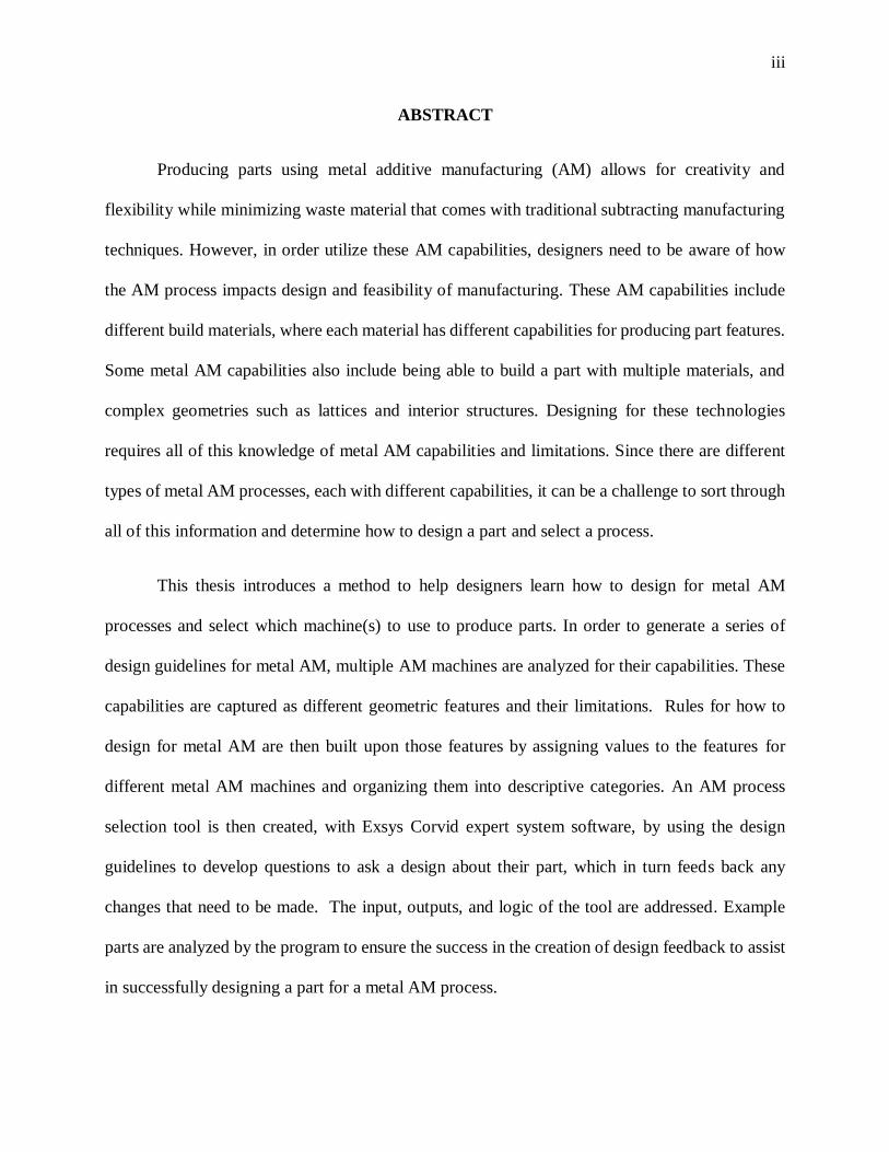
iii
ABSTRACT
Producing parts using metal additive manufacturing (AM) allows for creativity and
flexibility while minimizing waste material that comes with traditional subtracting manufacturing
techniques. However, in order utilize these AM capabilities, designers need to be aware of how
the AM process impacts design and feasibility of manufacturing. These AM capabilities include
different build materials, where each material has different capabilities for producing part features.
Some metal AM capabilities also include being able to build a part with multiple materials, and
complex geometries such as lattices and interior structures. Designing for these technologies
requires all of this knowledge of metal AM capabilities and limitations. Since there are different
types of metal AM processes, each with different capabilities, it can be a challenge to sort through
all of this information and determine how to design a part and select a process.
This thesis introduces a method to help designers learn how to design for metal AM
processes and select which machine(s) to use to produce parts. In order to generate a series of
design guidelines for metal AM, multiple AM machines are analyzed for their capabilities. These
capabilities are captured as different geometric features and their limitations. Rules for how to
design for metal AM are then built upon those features by assigning values to the features for
different metal AM machines and organizing them into descriptive categories. An AM process
selection tool is then created, with Exsys Corvid expert system software, by using the design
guidelines to develop questions to ask a design about their part, which in turn feeds back any
changes that need to be made. The input, outputs, and logic of the tool are addressed. Example
parts are analyzed by the program to ensure the success in the creation of design feedback to assist
in successfully designing a part for a metal AM process.
Page 4
iv
TABLE OF CONTENTS
LIST OF FIGURES ....................................................................................................................v
LIST OF TABLES ................................................................................................................... vii
ACKNOWLEDGEMENTS..................................................................................................... viii
Chapter 1 ....................................................................................................................................1
1.1 Motivation ....................................................................................................................1
1.2 Scope ............................................................................................................................2 1.3 Objectives .....................................................................................................................2
1.4 Organization of Thesis ..................................................................................................3
Chapter 2 ....................................................................................................................................4
2.1 Additive Manufacturing Overview ................................................................................4 2.2 Processes Descriptions ..................................................................................................8
2.3 Benchmarking Capabilities ......................................................................................... 13 2.4 Design for Additive Manufacturing Overview ............................................................. 14
2.5 AM Process Selection Overview ................................................................................. 17
Chapter 3 .................................................................................................................................. 19
3.1 Introduction ................................................................................................................ 19 3.2 Current CAD to Part Flow ........................................................................................... 20
3.3 Defining Features to be Benchmarked ......................................................................... 23 3.4 Development of Design Guidelines ............................................................................. 25
3.5 Summary ..................................................................................................................... 37
Chapter 4 .................................................................................................................................. 38
4.1 Introduction ................................................................................................................ 38 4.2 Determining Process Selection Inputs and Outputs ...................................................... 38
4.3 Ranking System .......................................................................................................... 45 4.4 Logical Flow ............................................................................................................... 47
4.5 Development of a Process Selection Tool .................................................................... 51 4.6 Examples Parts............................................................................................................ 60
4.7 Summary ..................................................................................................................... 69
Chapter 5 .................................................................................................................................. 70
REFERENCES ......................................................................................................................... 73
APPENDIX A Design Guidelines for Metal AM Comprehensive List ...................................... 78
APPENDIX B Metablock......................................................................................................... 81
Page 5
v
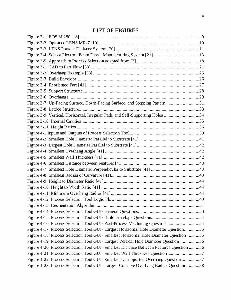
LIST OF FIGURES
Figure 2-1: EOS M 280 [18]........................................................................................................9
Figure 2-2: Optomec LENS MR-7 [19] ..................................................................................... 10
Figure 2-3: LENS Powder Delivery System [20] ....................................................................... 11
Figure 2-4: Sciaky Electron Beam Direct Manufacturing System [21] ....................................... 13
Figure 2-5: Approach to Process Selection adapted from [3] ..................................................... 18
Figure 3-1: CAD to Part Flow [33] ............................................................................................ 21
Figure 3-2: Overhang Example [33] .......................................................................................... 25
Figure 3-3: Build Envelope ....................................................................................................... 26
Figure 3-4: Reoriented Part [41] ................................................................................................ 27
Figure 3-5: Support Structures................................................................................................... 28
Figure 3-6: Overhangs ............................................................................................................... 29
Figure 3-7: Up-Facing Surface, Down-Facing Surface, and Stepping Pattern ............................ 31
Figure 3-8: Lattice Structure...................................................................................................... 33
Figure 3-9: Vertical, Horizontal, Irregular Path, and Self-Supporting Holes .............................. 34
Figure 3-10: Internal Cavities .................................................................................................... 35
Figure 3-11: Height Ratios ........................................................................................................ 36
Figure 4-1 Inputs and Outputs of Process Selection Tool ........................................................... 39
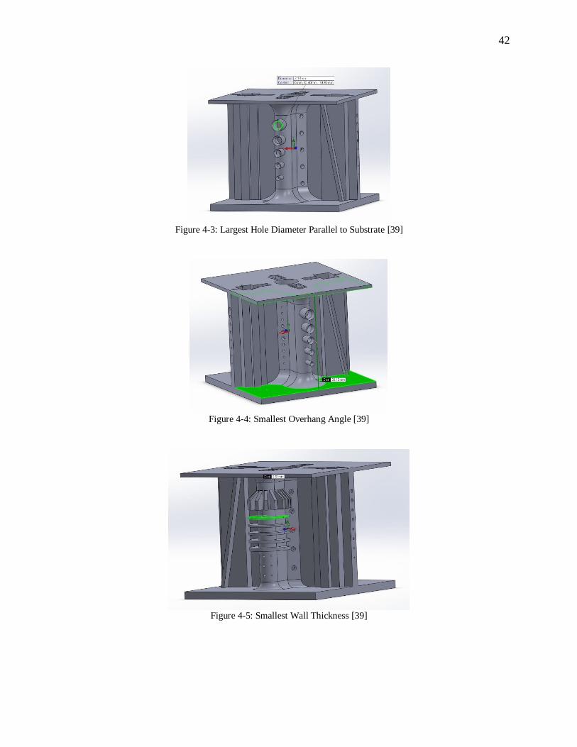
Figure 4-2: Smallest Hole Diameter Parallel to Substrate [41] ................................................... 41
Figure 4-3: Largest Hole Diameter Parallel to Substrate [41] ..................................................... 42
Figure 4-4: Smallest Overhang Angle [41] ................................................................................ 42
Figure 4-5: Smallest Wall Thickness [41] .................................................................................. 42
Figure 4-6: Smallest Distance between Features [41] ................................................................ 43
Figure 4-7: Smallest Hole Diameter Perpendicular to Substrate [41] ......................................... 43
Figure 4-8: Smallest Radius of Curvature [41]........................................................................... 43
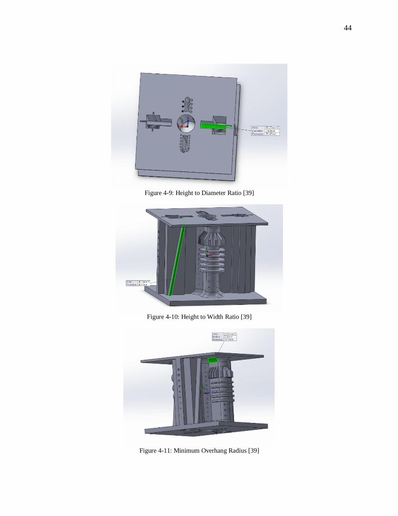
Figure 4-9: Height to Diameter Ratio [41] ................................................................................. 44
Figure 4-10: Height to Width Ratio [41] .................................................................................... 44
Figure 4-11: Minimum Overhang Radius [41] ........................................................................... 44
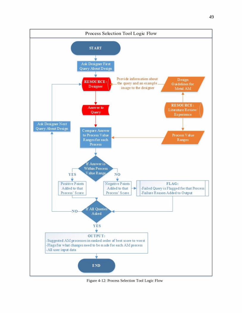
Figure 4-12: Process Selection Tool Logic Flow ....................................................................... 49
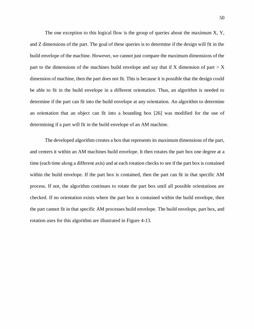
Figure 4-13: Reorientation Algorithm ....................................................................................... 51
Figure 4-14: Process Selection Tool GUI- General Questions .................................................... 53
Figure 4-15: Process Selection Tool GUI- Build Envelope Questions ........................................ 54
Figure 4-16: Process Selection Tool GUI- Post-Process Machining Question ............................ 54
Figure 4-17: Process Selection Tool GUI- Largest Horizontal Hole Diameter Question ............. 55
Figure 4-18: Process Selection Tool GUI- Smallest Horizontal Hole Diameter Question ........... 55
Figure 4-19: Process Selection Tool GUI- Largest Vertical Hole Diameter Question ................. 56
Figure 4-20: Process Selection Tool GUI- Smallest Distance Between Features Question ......... 56
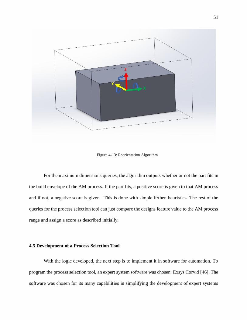
Figure 4-21: Process Selection Tool GUI- Smallest Wall Thickness Question ........................... 57
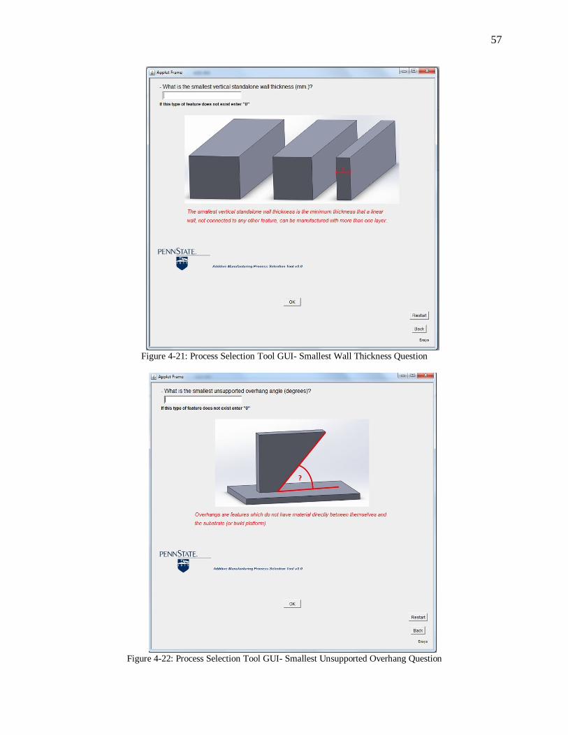
Figure 4-22: Process Selection Tool GUI- Smallest Unsupported Overhang Question ............... 57
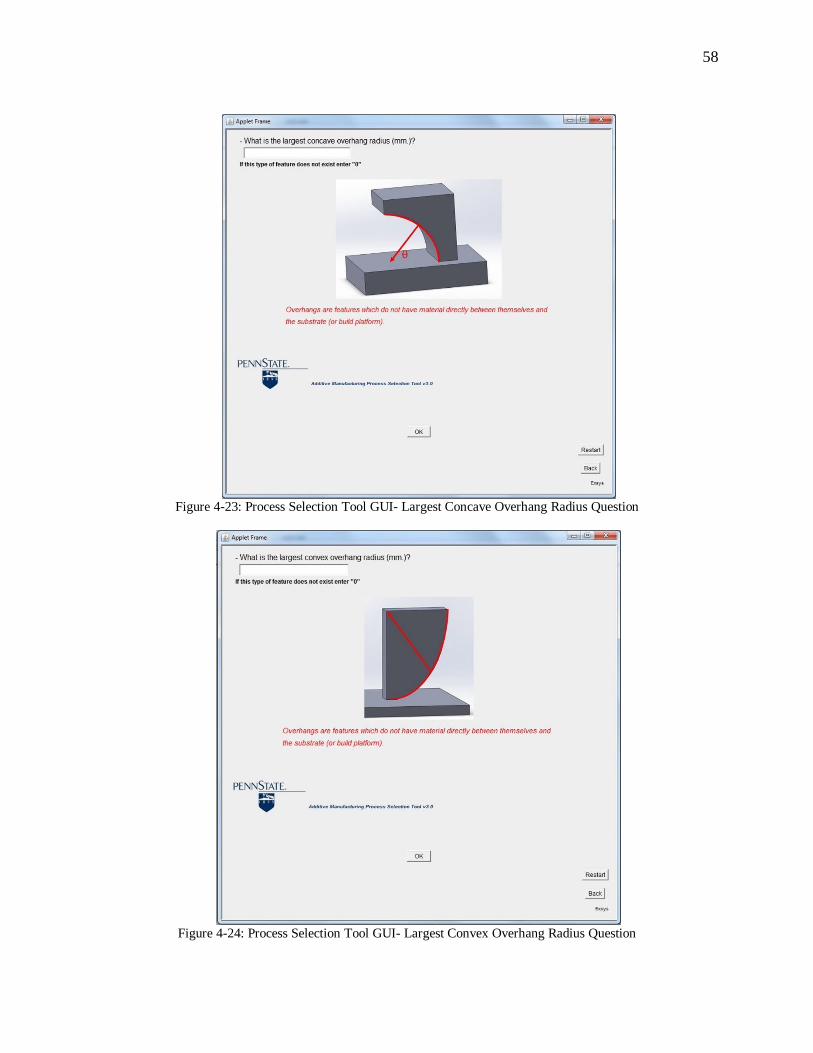
Figure 4-23: Process Selection Tool GUI- Largest Concave Overhang Radius Question............ 58
Page 6
vi
Figure 4-24: Process Selection Tool GUI- Largest Convex Overhang Radius Question ............. 58
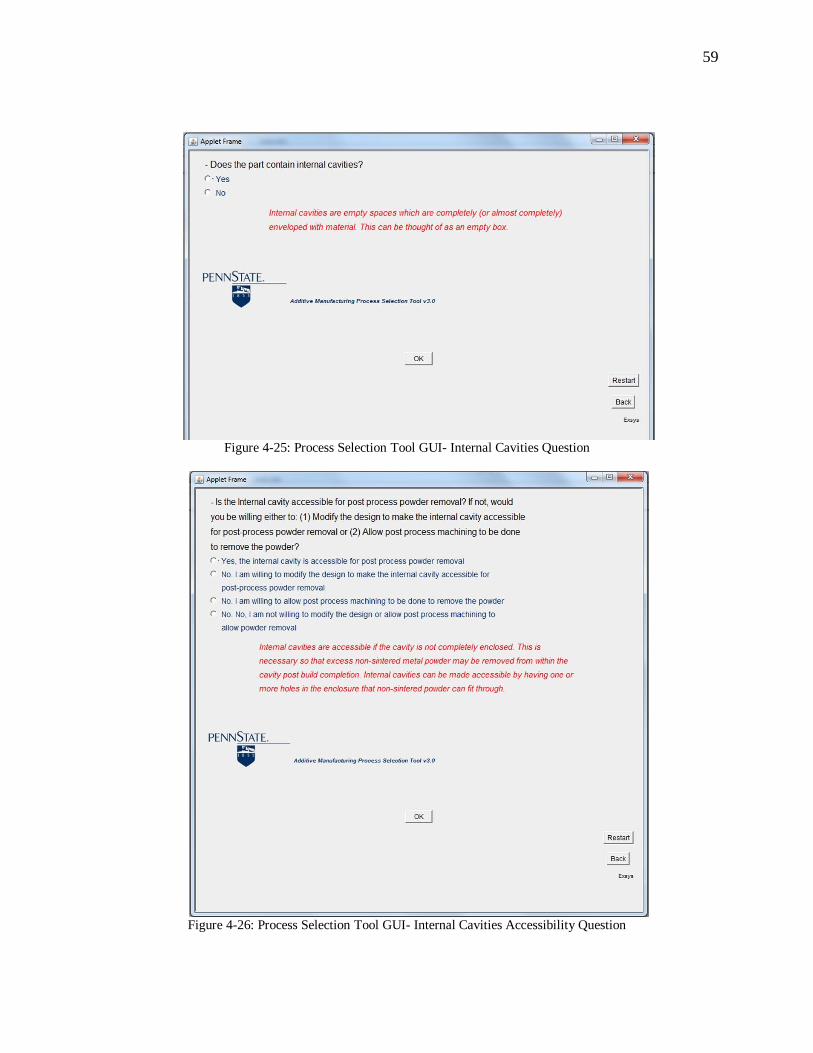
Figure 4-25: Process Selection Tool GUI- Internal Cavities Question ........................................ 59
Figure 4-26: Process Selection Tool GUI- Internal Cavities Accessibility Question ................... 59
Figure 4-27: Maximum Axes Dimensions ................................................................................. 61
Figure 4-28: Minimum Hole Perpendicular to Substrate and Minimum/Maximum Hole Parallel
to Substrate ............................................................................................................................... 62
Figure 4-29: Smallest Wall Thickness and Minimum Distance Between Features ..................... 62
Figure 4-30: Minimum Overhang Angle Cross-Sectional View ................................................. 62
Figure 4-31: Process Selection Tool Example 1 Output 1 .......................................................... 63
Figure 4-32: Process Selection Tool Example 1 Output 2 .......................................................... 64
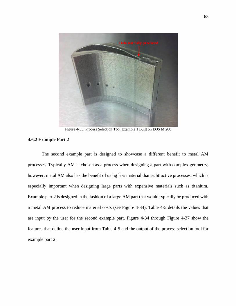
Figure 4-33: Process Selection Tool Example 1 Built on EOS M 280 ........................................ 65
Figure 4-34: Maximum Axes Dimensions ................................................................................. 66
Figure 4-35: Minimum Wall Thickness, Smallest Perpendicular Hole, Smallest Distance
Between Features ...................................................................................................................... 67
Figure 4-36: Process Selection Tool Example 2 Output 1 .......................................................... 67
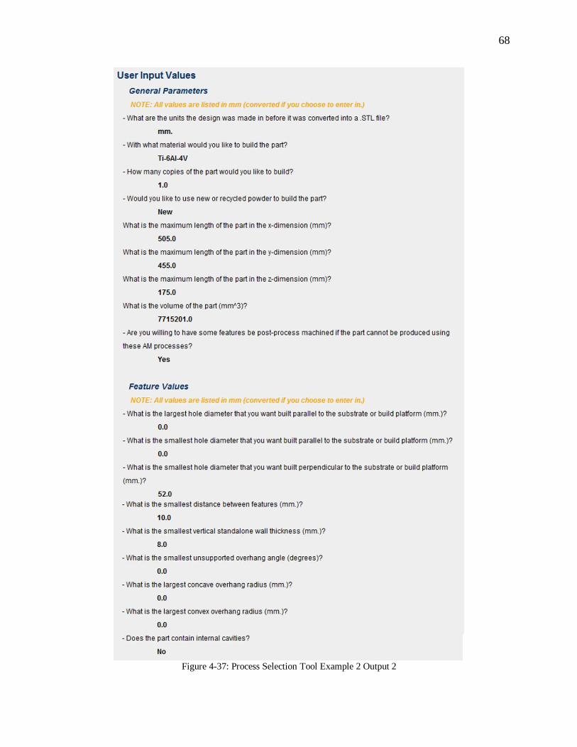
Figure 4-37: Process Selection Tool Example 2 Output 2 .......................................................... 68
Page 7
vii
LIST OF TABLES
Table 3-1: List of Feature Dependencies ................................................................................... 24
Table 3-2: EOS Cost/kg of Different Metal Powders as of 8/20/2013 [48] ................................. 32
Table 3-3: Height to Width Ratio [44] ....................................................................................... 36
Table 3-4: Height to Diameter Ratio [44] .................................................................................. 36
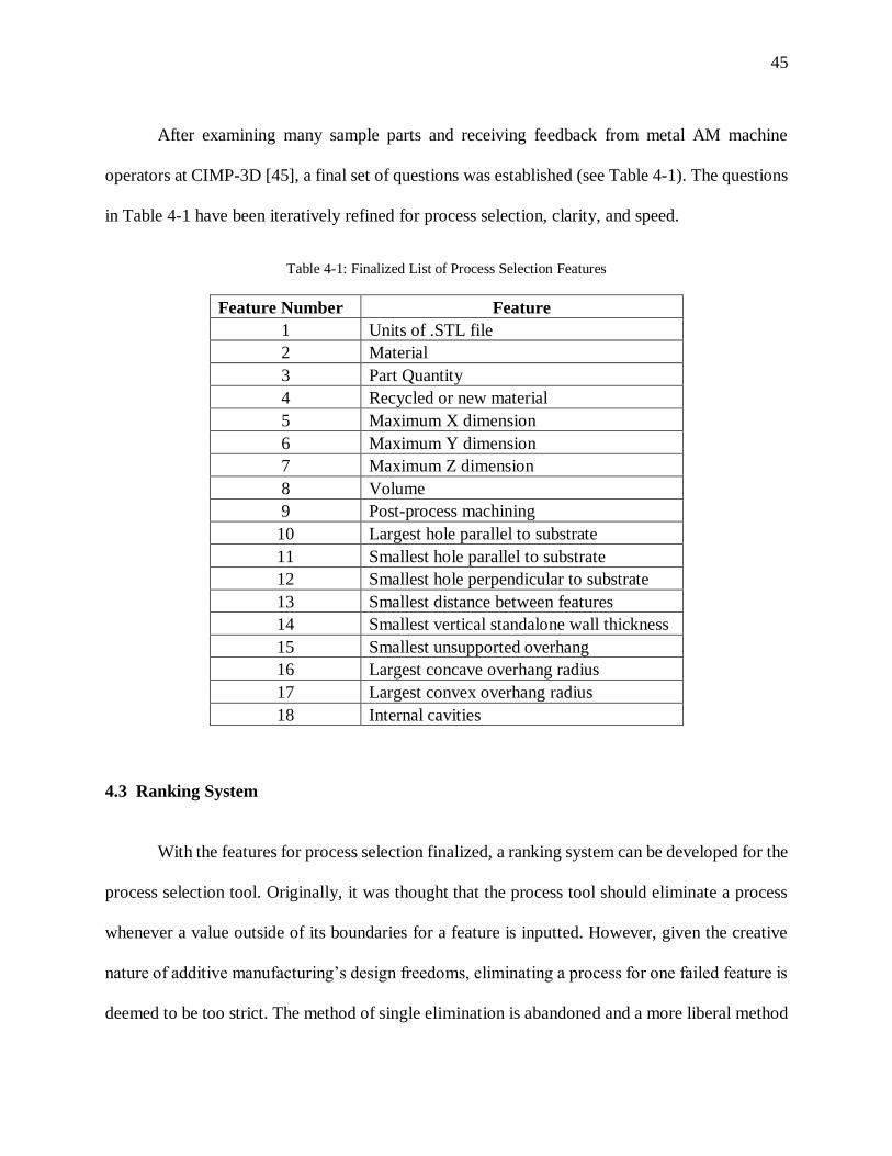
Table 4-1: Finalized List of Process Selection Features ............................................................. 45
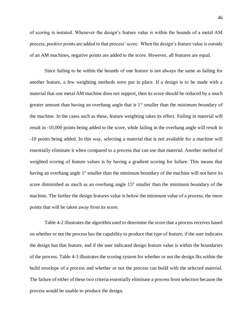
Table 4-2: Scoring Algorithm for Design Features .................................................................... 47
Table 4-3: Scoring Algorithm for Material and Build Envelope ................................................. 47
Table 4-4: Process Selection Tool Example Part 1 Input............................................................ 61
Table 4-5: Process Selection Tool Example Part 2 Input............................................................ 66
Page 8
viii
ACKNOWLEDGEMENTS
I would like to thank Dr. Timothy Simpson for his guidance through my undergraduate and
graduate career. It has been a wonderful experience getting to work with him over the past four
years, and his teachings have been invaluable in guiding my research and focus in this thesis.
Additionally, I would like to thank Dr. Sanjay Joshi for his input in my research and his help in
guiding me through my graduate career.
I would also like to thank Dr. Richard Martukanitz, Kenneth Meinert, and Corey Dickman
at Applied Research Labs for sponsoring me and this project as well as helping me discover my
focus. They have been incredible advisors in providing me experience with the additive
manufacturing machinery and providing support for me through this project.
Finally, I would like to thank my family for believing in me and encouraging me to be
the best I can be, and my friends for always being there with a helping hand and a good laugh.
Page 9
Chapter 1
Introduction
1.1 Motivation
President Barack Obama gave the first State of the Union speech of his second term on
February 12, 2013. One topic of this speech was the necessity to make the United States a world
leader in manufacturing which would subsequently bring jobs back from other countries to the
States. To support this, Obama “gave a shout-out to a growing technology:” 3D-printing, which is
also known as additive manufacturing (AM) [1]. This created a buzz in social media about AM,
saying that “3D printing that has the potential to revolutionize the way we make almost everything”
[1]. This buzz quickly spread around the world, generating more support and demand for AM,
which is a renewed driving force behind research in metal AM.
Metal AM gives us the ability to produce near-net shape parts that could not have been
built using traditional manufacturing methods. Even though there has been a high increase in
interest in these processing techniques, a strong foundation of research is lacking to establish its
capabilities [2]. Many companies and universities can build a small part or a prototype using metal
AM, but this does not utilize the full potential of these processes. In order to reach its full potential,
metal AM needs to have its capabilities better defined, and this knowledge needs to be made
readily available to designers, universities, and companies [2]. Not only do metal AM capabilities
need to be defined and compiled, but also there is a need to establish awareness of how to design
for these processes so that people can take full advantage of the capabilities that exist [3]. This
practice of designing products to reduce, and hopefully minimize, manufacturing and assembly
Page 10
2
difficulties and costs is known as design for manufacturability (DFM) [4]. Additionally, since there
are multiple different metal AM processes, designers need to be able to determine which process
to use for their part. The next steps to realize the full potential of this technology, allowing parts
to be made without wasting time or resources, are to benchmark different AM processes, develop
design guidelines, and construct a method of selecting a specific process.
1.2 Scope
The Applied Research Lab (ARL) at The Pennsylvania State University and the College of
Engineering, have established a research facility with funding from DARPA at Innovation Park in
State College, PA to be a center for AM. This facility, The Center for Innovative Material
Processing through Direct Digital Deposition (CIMP-3D), has multiple metal AM machines,
including the Optomec LENS MR-7, the EOS M 280, and a Sciaky electron beam process
(http://www.cimp-3d.org/). These machines are referenced throughout this thesis. The design
guidelines that are established focus primarily on the EOS M 280; however, they can be extended
to other metal AM processes once values for the machines are determined through experimentation
and industry collaboration of knowledge. The process selection tool that is developed,
incorporates a group of these design guidelines for the three processes mentioned, to minimize
end-user time.
1.3 Objectives
The goal in this research is to create a knowledge base of AM design guidelines and a
process selection tool. ASTM officially recognizes that there is a need for design guidelines
consisting of design rules, metal AM processes, materials, and values relating each process,
Page 11
3
material and rule together [3]. The knowledge base is composed of compiled DFM guidelines and
values from literature, experimentation, and industry reports. The DFM guidelines are made to be
expanded upon by adding more metal AM processes, rules, and their values, with the goal of being
a source of information available to all designers. The process selection tool will be based upon
suggestions in the literature [5]. The goal of the AM process selection tool is to allow designers to
be able to choose a metal AM process that will allow their part to be built, as well as be able to
teach some important design guidelines for metal AM. A designer that wants to use a metal AM
process to build a part would answer the questions asked about their part by the process selection
tool. The tool then provides a ranked order of the supported metal AM processes, feedback on the
part design, and links to more design guidelines.
1.4 Organization of Thesis
Chapter 2 examines the relevant literature in the area of additive manufacturing. This
includes an overview of additive manufacturing processes, the specific processes considered in
this thesis, determining the capabilities of AM processes, design for AM, and process selection.
Chapter 3 describes the development of design guidelines for metal AM. This includes the need
for design guidelines, the current flow from CAD to final part, determining and defining the
capabilities of metal AM processes, and the developed design guidelines specifically for the EOS
M 280 machine. Chapter 4 details the development of the AM process selection tool. This chapter
addresses the need for a process selection tool, the current methods used to select a process,
developing the logic for how a process is selected, creation of the process selection tool. It also
analyzes two sample parts through the process selection tool to illustrate how it works. Chapter 5
summarizes the contributions of the research and explores areas for future development.
Page 12
4
Chapter 2
Literature Review
2.1 Additive Manufacturing Overview
The difference between AM and typical subtractive manufacturing processes is that as
opposed to removing material from a block to shape a part, material is being added and joined
together layer by layer. Additive manufacturing, in its simplest form, is the generation of a part,
one layer at a time. Additive manufacturing technology is a term used to group together many
different manufacturing processes, which use different techniques that are each capable of
producing parts made from a wide selection of materials. A brief history of the development of
AM can be found in [6].
Despite only having been introduced to industrial application over the past few decades, ideas
behind AM begun as early as 1890, when Blanther [7] suggested a layered method for making a
mold for topographical relief maps. In his method, topographical contour lines were impressed on
wax plates, which were cut along the contour lines and stacked upon each other. Then the layers
were smoothed out, and a three-dimensional surface that corresponded to the terrain was created
[6]. Creating a 3D object layer-by-layer for AM was adapted in 1979 by Housholder [8], who
patented the earliest description of a powder laser sintering process in which layers could be
solidified selectively. As the processes of layer-based AM began to become more defined, it
became apparent that there were opportunities for it to be used industrially. From this discovery,
different AM technologies were developed such as laser engineered net shaping [9], direct metal
laser sintering [10], fused deposition modeling [11], 3D printing [12] and more. The processes all
differ by the types of geometries that can be created, the materials from which they are made, and
Page 13
5
the precision and the quality of the final parts that are produced [6]. Development of new AM
processes continued to develop until 1991, when the focus in the AM field shifted to improving
the processes that had already been created [13]. The improvements focused mainly on increasing
the speed at which the parts were built and increasing the types of materials used to make these
parts [14].
Even though many AM machines use similar methods and materials, there are key
differences between these processes that are crucial in selecting which processes to use for the
production of a part [8]. These differences are generally sorted into part geometry, machine
specifications, and materials. When looking at part geometry, AM provides a large increase in
geometrical freedom in comparison to typical manufacturing processes. The main factor for this
increase in design freedom is the ability to easily produce organic shapes, undercuts, and
overhangs. There are also limitations to the capabilities of AM such as the size of the part [2].
Small to medium sized parts are usually not a problem to build, but large parts can create
difficulties. For parts larger than the build envelope of an additive manufacturing process, the parts
need to be split apart to be produced separately and then joined together afterwards. Splitting up a
part and putting it back together can be difficult, time consuming, and therefore costly. In contrast
to this, very small parts can be made with greater precision and accuracy than by most typical
process [8]. This advantage exists because of the precision that can be achieved with a computer-
controlled system.
When looking at the additive manufacturing machines, many specifications vary across
different machines. One instance is that different processes and machines have different maximum
speeds. With different maximum speeds comes different productivity rates. For the most part, AM
technology is slower than tradition manufacturing methods [8]. The productivity rate of AM
Page 14
6
systems can speed up by using machines that incorporate multiple lasers or extruders. For some
additive manufacturing processes, post-process machining is necessary for the removal of support
structures that helped stabilize the part during production [8]. Another specification that varies
from machine to machine is accuracy. Since accuracy and precision are very important to the
overall part, parts with dimensionally critical structures need to utilize AM machines whose
accuracy correlates with the part tolerances.
Most likely the largest difference between additive manufacturing technologies is the
selection of materials that the machines can utilize. Just because one AM process can build parts
made of titanium, for example, does not mean that another process is capable of doing the same.
Each machine has a specific set of materials from which to choose. The largest difference in
materials between machines is polymers and metals. Often, the changes in material also effect the
geometric design freedom and machine specifications. By choosing a specific material to fabricate
a part, a designer is forced to select from a much smaller pool of AM technologies.
Currently, many issues exist with AM that need to be addressed to use these processes.
One of the largest issues is the selection of materials and its impact on the design [2]. In most
cases, the selection of a material for a part, in combination with a specific process, defines the
geometric limitations of the parts design. With many different possible materials to choose from,
a designer must be aware of all the different material properties and the limitations that they incur
upon the design. All of these material properties and their effects on designs need to be gathered
and compiled [2]. At this time, however, it is not known who should be generating, compiling, and
distributing this data [2]. Machine manufacturers tend to treat a portion of this information as
trade secrets and require payment for sharing it as an add-on to their software packages. Despite
the wide range of materials that AM can produce, there is still a need to develop compatibility with
Page 15
7
more materials. More material compatibility would create more opportunities and potential
applications for AM processes [2].
Another major difficulty for AM to overcome is the limited knowledge that the designers
have about the technology. With every manufacturing process comes a set of capabilities and
limitations, and one must understand them for the potential of the technology to be fully realized
[4]. Since additive manufacturing technology is relatively new to most designers, there is an
overall lack of understanding of how to design for it [15]. This creates a large amount of confusion
and iterative nature in using AM processes. If designers do not know what limitations there are,
they will have to repeatedly make edits to their designs before parts qualify as producible. If they
knew how to design for the process in the first place, then they may have come up with a
completely different and possibly better part design. Armed with the knowledge of how to design
for additive manufacturing, the AM industry and those who choose to utilize it could grow
dramatically.
Another hurdle that additive manufacturing technologies needs to overcome is
standardization of the process. Standards range from being certified to build mission critical parts,
to process standards that need to be established and distributed [16]. With additive manufacturing
standards in place, more designs can be made for AM allowing for more facilities to open and the
industry to expand.
The future for additive manufacturing is predicted to be bright and revolutionary [17]. As
additive manufacturing progresses, it is expected to become more energy efficient as sustainable
methods are linked with design [17]. It is expected that there will be an increase in design
inspiration coming from biology and nature [17]. The desire for customizable parts, allowing for
Page 16
8
prototyping and the ability for manufacturers to quickly adapt to customer needs is growing and
only expected to increase. These developments lend themselves to additive manufacturing’s
capabilities. Therefore, information needs to be broadcasted to designers about how to utilize these
technologies so that they are ready to meet these demands [17].
2.2 Processes Descriptions
The current implementation is limited to machines and technologies available at CIMP-3D.
2.2.1 Powder Bed Fusion (Direct Metal Laser Sintering): EOS M 280
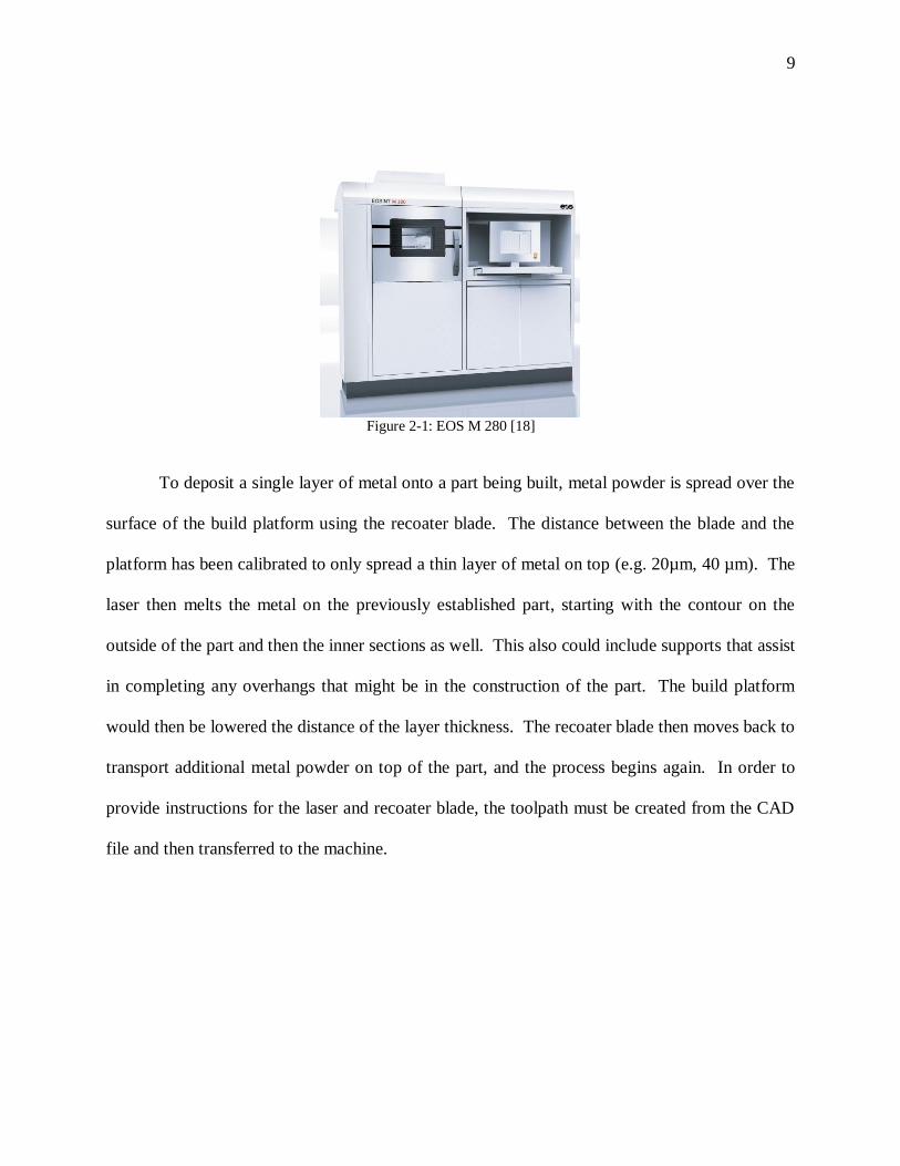
The EOSINT M 280 (see Figure 2-1) machine was chosen as the primary focus AM machine
to be used in developing design for metal AM guidelines because of the availability of
benchmarking information. The EOSINT M 280 is an additive manufacturing machine that utilizes
direct metal laser melting for the creation of tooling inserts, prototyping parts, and end products
created in metal. The system has a build envelope, including the build platform, of 250 mm X 250
mm X 325 mm. Complex geometries are able to be produced by melting metal powder inside the
machine using a 400 Watt laser in a layer-by-layer fashion. The system can utilize both nitrogen
and argon to provide an inert atmosphere, and there are sensors inside the machine to detect the
parts per million (PPM) of oxygen during the production. The gas chosen is dependent on the
metal powder in the machine at the time. The scan speed can be up to 70 mm/s. Commercially
available parameter sets can be used to establish settings on the machine, and these sets are material
dependent [18].
Page 17
9
Figure 2-1: EOS M 280 [18]
To deposit a single layer of metal onto a part being built, metal powder is spread over the
surface of the build platform using the recoater blade. The distance between the blade and the
platform has been calibrated to only spread a thin layer of metal on top (e.g. 20µm, 40 µm). The
laser then melts the metal on the previously established part, starting with the contour on the
outside of the part and then the inner sections as well. This also could include supports that assist
in completing any overhangs that might be in the construction of the part. The build platform
would then be lowered the distance of the layer thickness. The recoater blade then moves back to
transport additional metal powder on top of the part, and the process begins again. In order to
provide instructions for the laser and recoater blade, the toolpath must be created from the CAD
file and then transferred to the machine.
Page 18
10
2.2.2 Directed Energy Deposition: LENS MR-7
The Optomec LENS MR-7 system (see Figure 2-2) was chosen as a secondary focus AM
machine to be used as a comparison in process selection. It also enables a comparison between
different metal AM processes. The LENS MR-7 is a metal additive manufacturing machine that
uses a laser engineered net shaping (LENS) process for prototyping, the creation of near net shape
parts, and repairing metal parts. The system has a build envelope, including the building stage, of
300 mm X 300 mm X 300 mm [19]. Intricate parts are producible by melting metal powder with
a maximum of 500 Watt fiber laser, in the typical one layer at a time AM style. The environment
of the build chamber is controlled to be optimal for melting by maintaining oxygen at less than 10
PPM. The scan speed can reach 60 mm/s, and material can be deposited at up to 100 g/hour. The
machine relies on a part file from CAD software as most AM processes do. The software that
comes with the machine allows for flexible customization of parameters such as scan speed, layer
thickness, laser power, and powder deposition rate. However, one needs to determine the optimal
settings for each material they use in order to produce quality parts [20].
Figure 2-2: Optomec LENS MR-7 [19]
Page 19
11
There are some differences in the LENS system compared to other metal AM processes.
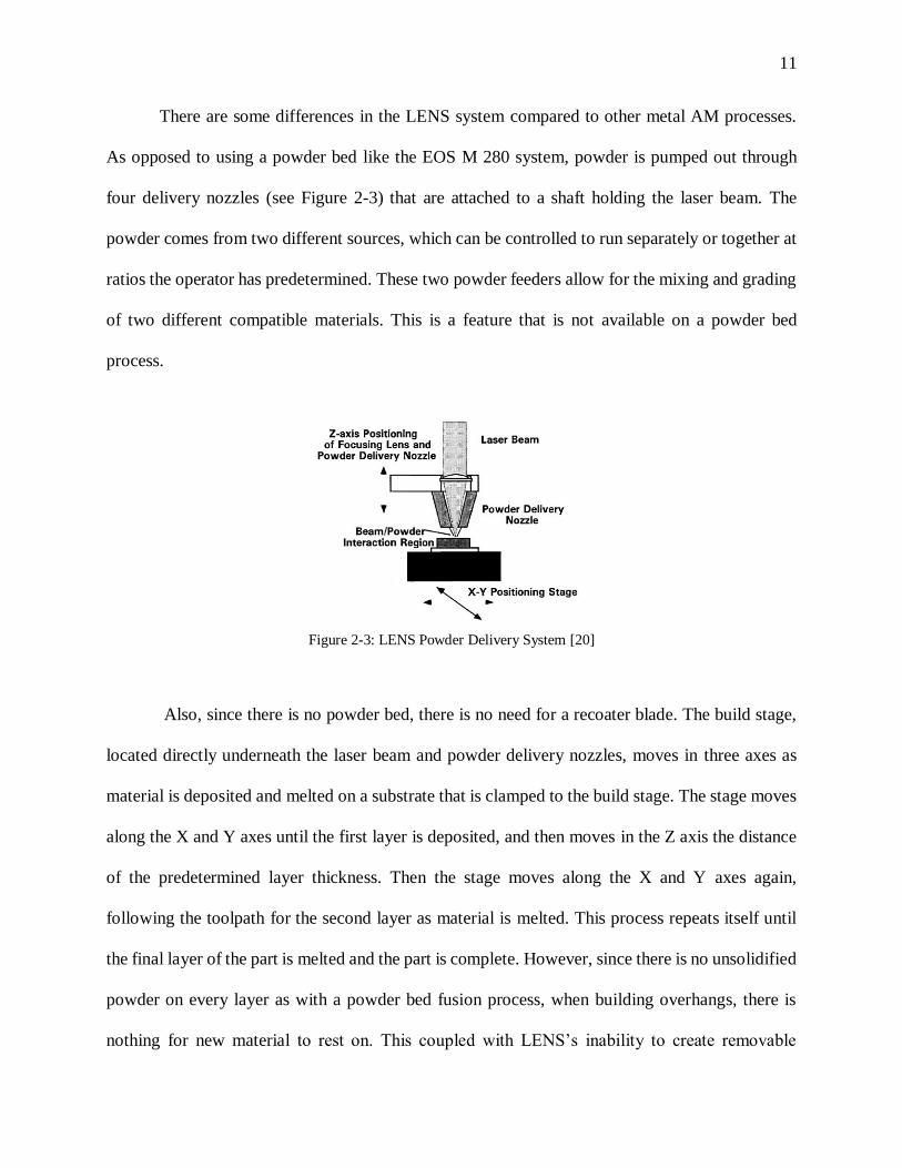
As opposed to using a powder bed like the EOS M 280 system, powder is pumped out through
four delivery nozzles (see Figure 2-3) that are attached to a shaft holding the laser beam. The
powder comes from two different sources, which can be controlled to run separately or together at
ratios the operator has predetermined. These two powder feeders allow for the mixing and grading
of two different compatible materials. This is a feature that is not available on a powder bed
process.
Figure 2-3: LENS Powder Delivery System [20]
Also, since there is no powder bed, there is no need for a recoater blade. The build stage,
located directly underneath the laser beam and powder delivery nozzles, moves in three axes as
material is deposited and melted on a substrate that is clamped to the build stage. The stage moves
along the X and Y axes until the first layer is deposited, and then moves in the Z axis the distance
of the predetermined layer thickness. Then the stage moves along the X and Y axes again,
following the toolpath for the second layer as material is melted. This process repeats itself until
the final layer of the part is melted and the part is complete. However, since there is no unsolidified
powder on every layer as with a powder bed fusion process, when building overhangs, there is
nothing for new material to rest on. This coupled with LENS’s inability to create removable
Page 20
12
support structures, limits the production of overhangs. Therefore there is a need for designers to
plan ahead for this limitation and to develop their part oriented in a way that can be built from the
ground up.
2.2.3 Directed Energy Deposition: Sciaky E-Beam
The Sciaky Electron Beam Direct Manufacturing (EBDM) system (see Figure 2-4) was
chosen as a tertiary focus AM machine to be used as a comparison in process selection. It also
enables a comparison between different metal AM processes. The EBDM has a build envelope of
1270 mm X 760 mm X 1270 mm which must be vacuum sealed for the electron beam process to
work. The large build envelope lends itself to EBDM’s main purpose that is to produce large parts
at a near net-shape. This can reduce material costs when compared to typical subtractive
manufacturing, where a stock block of material would be purchased and then machined away. The
material is wire fed as is done in electron beam welding. Similar to the LENS machine, Sciaky’s
EBDM is not a powder bed process and therefore overhangs are next to impossible. However, this
machine can also lay down up to 250 cubic inches per hour which is very quick for an AM process
[21]. Since large quantities of material are being laid down quickly, the final part is planned to be
near net-shaped, and post-process machining on the part is necessary. This process therefore lends
itself to very large parts composed of expensive materials because it allows for less of that material
to be used than in subtractive manufacturing. There are many different situations for which metal
AM processes are ideally suited. Some processes are suited for large, near net-shape parts like
EBDM and others are suited for smaller complex geometries such as powder bed fusion. This
creates a need for determining the specific capabilities of each process and each machine [11].
Page 21
13
Figure 2-4: Sciaky Electron Beam Direct Manufacturing System [21]
2.3 Benchmarking Capabilities
The technology to create precise parts from a 3D CAD file with AM exist today, and
research has begun to define what these commercially available AM processes are capable of
accomplishing. The process of measuring the accuracy, finish quality, repeatability, resolution,
and the maximum and minimum geometrical features of the parts produced is called benchmarking
[22]. Benchmarking studies on regular manufacturing methods and processes have been carried
out, resulting in guidelines for designers to tailor their designs to the specific machines capabilities,
which is also known as design for manufacturing (DFM) [22]. However, due to their unique
processes, AM methods are capable of creating much more complex parts than typical
manufacturing methods, which allows the designers to create intricate designs [22]. Even though
AM technologies are capable of creating very complicated parts, there are still limitations to the
machines that designers need to be made aware of, before finalizing their parts, in order to
implement DFM. Benchmarking results already exist for some AM technologies [11].
A compilation of benchmark results for all available AM technologies has been noted as
an item of interest because designers would then be capable of choosing the best AM process to
Page 22
14
suit their parts. However, no formal compilation or process to create such a compilation exists to
date [2]. This need for a compilation of features is well-known to AM designers as there are groups
that are working to collect benchmark rules for AM machines to create a "Guide for Design for
Additive Manufacturing" [3]. Efforts such as these are often done by surveying companies, many
of which do not want to share the rules they have developed and knowledge that they have gained
through experience as they provide them with a competitive advantage in the marketplace. Without
this knowledge being shared and readily available, attempts to compile a list of machine design
rules has remains elusive.
2.4 Design for Additive Manufacturing Overview
Design for manufacturability (DFM) is the practice of designing products to reduce, and
hopefully minimize, manufacturing and assembly difficulties and costs [4]. In simple terms, DFM
is the engineering practice of designing products in a manner that makes them easy to manufacture.
This engineering technique focuses not only on the design of a part but also on its producibility.
The ease of producing a part with a manufacturing process can dramatically reduce its
manufacturing costs. Producibility is not only affected by the manufacturing process but also by
the geometry of the part, the dimensional tolerances of the design, the type of raw building
material, the form of the material, and post-processing of the part [23].
An extensive amount of work has been done in DFM, going back even as far as Henry Ford
and his Model T: “… Costs had been lowered by concentrating on the fewest possible standard
parts and designing machines to turn them out- them and nothing else- automatically if could be”
[24]. In his book, My Life and Work, Ford focused on simplicity of design for the Model T because
Page 23
15
“The less complex the article, the easier it is to make, the cheaper it may be sold” [25]. It can be
seen that much of what Ford accomplished is now referred to as DFM.
Currently DFM guidelines for different machining processes can be found on company
websites [50, 27] and in the literature [24, 51]. Some machining processes that DFM design
guidelines have been developed for are milling, electrical discharge machining (EDM), turning,
drilling, and CNC machining [24]. Design guidelines for machining processes can be general,
such as minimizing the total number of parts and using standard components [26], or they can be
about specific features, such as fillets on top edges and deep radius corners in the milling process
[27]. DFM is a system of guidelines that is continually being refined and developed as new
manufacturing processes become available [24].
Design for additive manufacturing (DFAM), DFM specifically for additive manufacturing,
has been primarily focused on plastic materials in the past, but the AM community has only
recently begun delving deeper into looking at DFAM in metals [2]. Many of the same DFAM
concepts carry over from plastics to metals. 3D-printing in plastics allows designers many
freedoms in their designs [28]; however, this depends on the specific plastic AM process. These
processes can range from do-it-yourself (DIY) 3D printers that extrude plastic filament like a hot
glue gun on a 3-axis controlled machine to commercial fused deposition modeling (FDM)
machines that print plastic filament as well as water soluble filament that act as support structures.
A DIY home 3D printer typically has no secondary material to use for support structures,
a low resolution which creates a largely visible stepping pattern, and are often simply unreliable
[29]. On the other hand, FDM printers give the ability to print almost any geometry, using the
water soluble material as filler material to support the design as long as the filler material is
Page 24
16
accessible to water when the build is finished. Despite quality differences, the same type of rules
apply to FDM as well as DIY home printers. Designs must fit within the build envelope of the
process, have minimum wall thicknesses and feature sizes based off of the resolution of the
machine, as well as minimum unsupported overhang angles. These same design concepts apply to
metal AM as well; however, there has been much more development in polymer AM to the extent
of even having a large scale open-source development community [12]. Many commercially
available polymer 3D-printer companies post design guidelines on their websites [21, 35], and
papers as well as books [4] are written about DFAM for plastics.
In contrast, the magnitude of support for the metal AM community is much smaller, but
starting to grow [6]. Another major difference is that with metals, with different materials come
different material properties and potentially different numerical values for each of the design
considerations. Because of this, AM process parameters such as laser power, hatch spacing and
layer thickness need to be identified for each material [30]. Once those process parameters are
developed for a specific machine, guidelines for that specific material on that specific machine can
be developed by analyzing benchmarking parts. Since, for many of the metal AM machines, the
machine manufacturers treat the process parameters as trade secret that can be bought as an add-
on in a software package, it has been difficult to define values for guidelines for DFAM. ASTM
officially recognizes that design guidelines need to be collected, compiled, and put in place for
plastic and specifically metal processes [3]. For a database such as this to exist, the type of design
features that need guideline values also needs to be collected and compiled in a similar format.
One such format could provide descriptions of important design features to support the
understanding of AM, as well as examples of those features with all known guideline values
specific to individual processes and machines.
Page 25
17
2.5 AM Process Selection Overview
In 2013, there existed over 45 manufacturers of AM equipment [31], a number which
continues to grow [32]. Many of these manufacturers produce multiple AM machines with
different capabilities. There are currently less than 15 AM processes that are utilized by many
more AM machines [3]. With all of these different AM technologies available, selecting a specific
process to use can become a difficult task. This task is made even more challenging for those with
little to no technical experience with AM [32].
To combat the issue of AM process selection for those with limited technical knowledge
of AM, process selection tools have been developed. Selection tools that currently exist do provide
some basic functionality in choosing a specific process based off of selection criteria such as
material, part quantity, part volume, surface finish, minimum wall thickness, temperature
properties, and color (specific to polymers) [33]. These criteria are helpful in narrowing down
processes, but they can end up recommending a machine that is not capable of producing the part
that is designed. With more information about the processes geometric capabilities and the design
geometry, a more effective tool could be constructed.
To determine how to develop an effective process selection tool, the requirements of such
a tool have been examined by the AM community. An additive manufacturing process selection
tool for any knowledge level user should contain the following considerations [4, 49]:
- The information in the system should be unbiased whenever possible.
- The system should provide support and advice rather just a quantified result.
- The system should provide an introduction to AM to equip the user with
background knowledge as well as advice on different AM technologies.
Page 26
18
- A range of options should be given to the user in order to adjust the requirements
and show how changes in requirements may affect the decision.
- The system should be linked to a comprehensive and up-to-date database of AM
machines.
- Once the search process has completed, the system should give guidance on where
to look next for additional information.
- The system should provide fast, direct access to a great amount of information
about practical AM methods.
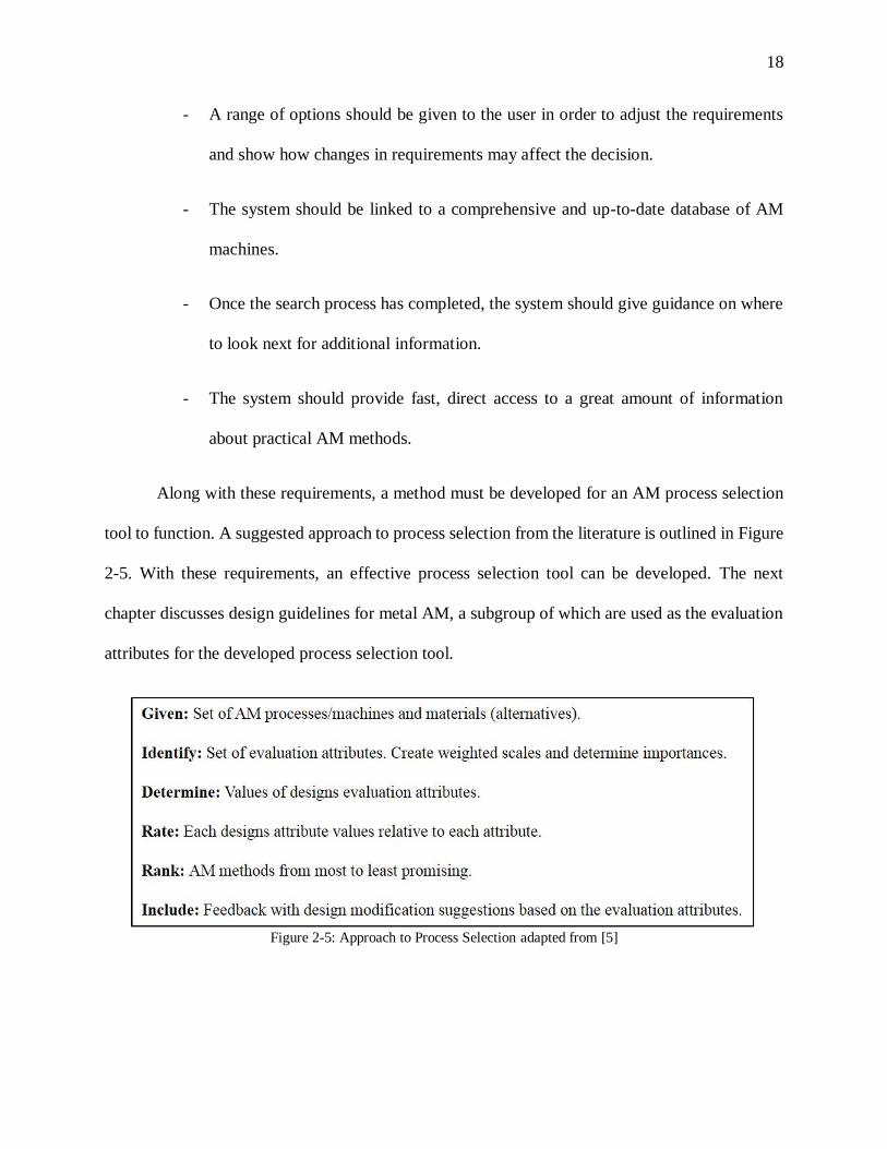
Along with these requirements, a method must be developed for an AM process selection
tool to function. A suggested approach to process selection from the literature is outlined in Figure
2-5. With these requirements, an effective process selection tool can be developed. The next
chapter discusses design guidelines for metal AM, a subgroup of which are used as the evaluation
attributes for the developed process selection tool.
Figure 2-5: Approach to Process Selection adapted from [5]
Page 27
19
Chapter 3
Design for Metal Additive Manufacturing Guidelines
3.1 Introduction
Since additive manufacturing has been put in the spotlight by the media, many people
believe additive manufacturing can do much more than it is capable of doing. AM is a
manufacturing technique that enables the creation of designs that could never have been built with
regular manufacturing processes. However, AM is not a capable of revolutionizing “the way we
build everything” [1]. AM is a powerful and sophisticated manufacturing resource that enables the
creation of designs that were not possible before, but it needs to be understood in its own terms
[34]. For instance, in many metal AM processes it is not possible to create support structures,
which makes building overhangs next to impossible. There are ways to overcome this limitation
by re-orienting the design in the build volume, but the part needs to be designed in such a way that
an orientation without the need for support structures exists. The selection of a metal AM process
utilizing a 5-axis tilt table would also enable the designer to build overhangs. This is just one of
many new caveats that designers need to take into consideration when designing for metal AM.
Currently there is no complete source for design guidelines for metal AM to allow a
designer to learn this information. Individual design guidelines exist for specific machines, but
they may not be complete (e.g., [35]). In order for guidelines to be useful to designers, they need
to consist of rules with numeric values for the limitations of a machine. Since there is a vast amount
of information that needs to be collected and compiled, industry and academia need to collaborate
to establish a common source for this information.
Page 28
20
This chapter proposes a set of guidelines, specifically for the EOS M 280 machine, that are
formatted and categorized for accessibility to designers. However, before rules can be created, we
must examine the process of how a design becomes a part, to determine what the rules need to take
into consideration. This chapter takes a look at the process that a design goes through to become a
part in metal AM. Then knowledge from that process as well as the literature is applied to
determine the capabilities of metal AM processes. These capabilities are used to inform the
designer of the limits that metal AM processes put on a design. This chapter then turns those
limitations into design guidelines for metal AM.
3.2 Current CAD to Part Flow
The flow from design to final part is described and illustrated in Figure 3-1. A design needs
to be created to start the process of building a part, which can be done using one of many computer
aided design (CAD) software packages. The standard for a design file in AM is to be in the .STL
format. This means that whatever CAD software is chosen to design the part needs to be able to
output the design as a .STL. An STL file is comprised of very tiny triangles that are meshed
together to form the surface of the design. No other information such as design features, volume,
or sizes are contained in this file. The designer then sends the .STL file to the AM technician,
letting the technician know what material to build the part with as well as what units the .STL file
was generated in (either English or SI).
Page 29
21
Figure 3-1: CAD to Part Flow [36]
The next step is for the design to be sliced into layers. Since AM prints in a layer by layer
fashion, the machine needs to know what to print on each layer individually. However, before
slicing the .STL file, it must be oriented in the way that the machine will build it. Build orientation
is a very important part of AM because it is largely responsible for determining whether a part can
be built with AM and dictates build time and accuracy. This is because features of a part may be
producible in some orientations and not in others. Build orientation and the height of the build are
discussed further in Section 3.4.
Once the design is oriented in a way that it can be produced, all that is left to do is specify
the thickness of each slice layer. This decision will affect the final resolution of the part in the
vertical direction of the print: the thicker the layer, the lower the resolution and vice versa. This
affects the resolution because it creates a stepping pattern, which is discussed in Section 3.4. Each
Page 30
22
machine has different limits of how small the layers can be made, which also differ from material
to material.
Once a layer thickness is selected as well as a producible build orientation, then the .STL
file can be sliced. The slicing of the .STL file can be done with many different software packages,
including freeware (e.g., Netfabb [37]), machine-specific software (e.g., Part Prep [19]), or
professional software made specifically for slicing and handling AM designs (e.g., Magics [38]).
Some slicing software are only one part of a larger AM program (e.g., Magics [38]). Generally,
slicing software takes the input of a .STL file, slices it, and outputs a .SLI file. A .SLI file is a file
format that contains the thickness of each layer as well as the area of that layer which will need
material built upon.
After the .SLI file is generated, an individual path on each layer, called a toolpath, needs
to be developed. There are many software for this process as well (e.g., Part Prep [19], Direct Tool
[18]). It is a common occurrence for toolpath generation and slicing to be included in the same
AM software. During the toolpath generation phase there are many decisions that need to be made
such as the algorithm chosen for the pattern of the toolpath (spiraling in towards the center, linear
patterns, etc.), the spacing between each line of the toolpath (i.e., hatch spacing), if the outer
contour of the toolpath will be thicker than the inside, and many other options. These decisions
can affect the part microstructure, the amount of time for the build, the uniformity of each layer,
and many more aspects of the final finished part. Once all of the decisions are made, the toolpath
can be generated, which is typically output in the file format .GCODE, although other similar
formats exist and can vary from process to process (e.g., .DMC [19] ). A .GCODE file contains
the vectors of the toolpath and their order for each layer of the part.
Page 31
23
Once the .GCODE is created, it can then be uploaded to the AM machine, where another
set of decisions need to be made before finally printing the part. Depending on the machine, these
decisions may need to be made before generating the .GCODE. The choices in this step include,
but are not limited to, the machine build speed, the laser power, material deposition rate, and the
amount of wait time between layers. The print speed, laser power, wait time, and material
deposition rate all affect the amount of material that is actually laid down for the part. The wrong
combination of values for these parameters can result in the thickness of each layer being greater
or less than the layer thickness of each horizontal slice of the part. If the actual layer thickness and
the predetermined slice layer thickness do not match, then the part will not build correctly and will
therefore not be dimensionally accurate, rendering the part useless.
3.3 Defining Features to be Benchmarked
Now that we understand the path that a design takes on its way to become a part in metal
AM, we need to look at what limitations this puts on the design in order to generate guidelines for
designers. To capture these limitations in a form that designers can take advantage of, they are
sorted into design features in this work. These features can be things from comparing the size of a
design to the build envelope of a specific metal AM machine, to a geometric feature of the part
such as hole shape.
The design features divided into three categories: (1) machine dependent features (MAC),
(2) material dependent features (MAT), and (3) orientation dependent features (O). Some features
may fall into multiple categories. Most features are a combination of material dependent features
Page 32
24
and another category. A list of features and their dependencies, compiled from experience,
industry, and literature review can be found in Table 3-1.
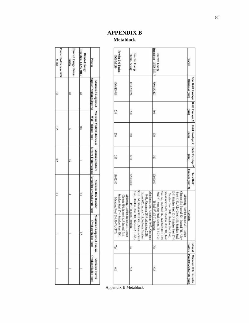
Table 3-1: List of Feature Dependencies
Feature Number Feature Dependency Source
1 Build Envelope MAC [18, 10, 21]
2 Support Structures MAT, O [10, 35, 41, 40]
3 Overhangs MAT, O [33, 41, 44]
4 Tolerances MAC [40, 42, 48]
5 Surface Finish MAT, O [10, 41, 48]
6 Innovative Geometries MAT, MAC, O [20, 40, 48]
7 Holes MAT, O [41, 40]
8 Interior Features MAC, O [10, 40]
9 Height Ratios and Wall Thicknesses MAT, MAC, O [19, 44]
10 Minimum Feature Size MAT, MAC [18, 40]
Table 3-1 lists categories of capability features, comparing the features to their
dependencies. This list of features is made to be added to as designs become more creative and
new features are developed. These capability feature categories all create restraints upon what a
designer will be able to produce using a metal AM process. The features themselves are examined
and described in section 3.4.
Machine dependent features are features that vary from machine to machine. These are
typically physical machine limitations such as the size of the build envelope. The size of the EOS
M 280 build envelope is different than the build envelope of the Optomec MR-7. While technically
all features are machine dependent because each machine is capable of producing features within
different ranges, only the features that were strictly about the machine specifications are listed as
machine dependent features.
Page 33
25
Material dependent features are features that vary from material to material for individual
machines. This means that while the wall thickness on a machine for stainless steel may have a
minimum of 1 mm, for Inconel 718 or any other material, that value may be different.
Orientation dependent features are features that vary in a specific machine’s ability to
produce it based as the orientation of the part within the build envelope. This means that an
overhang angle of 20° from the substrate may be impossible to build originally, but if the part is
reoriented vertically in the build envelope, then the overhang angle can become 70° which is
buildable (see Figure 3-2).
Figure 3-2: Overhang Example [36]
3.4 Development of Design Guidelines
Armed with the understanding of how the capabilities and limits of a metal AM process
relate to design features via dependencies, we can now compile and develop guidelines for how to
design for these types of processes. This section describes the categories of features defined in
Table 3-1 and defines rules (guidelines) for them. All numeric values for these guidelines are
Page 34
26
general values for the EOS M 280 machine, which is a powder bed process. A comprehensive list
of rules for design for metal AM compiled from available literature can be found in Appendix A.
3.4.1 Build Envelope
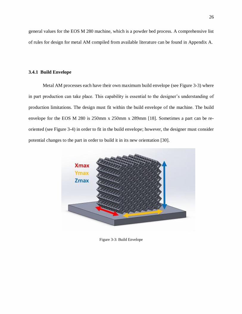
Metal AM processes each have their own maximum build envelope (see Figure 3-3) where
in part production can take place. This capability is essential to the designer’s understanding of
production limitations. The design must fit within the build envelope of the machine. The build
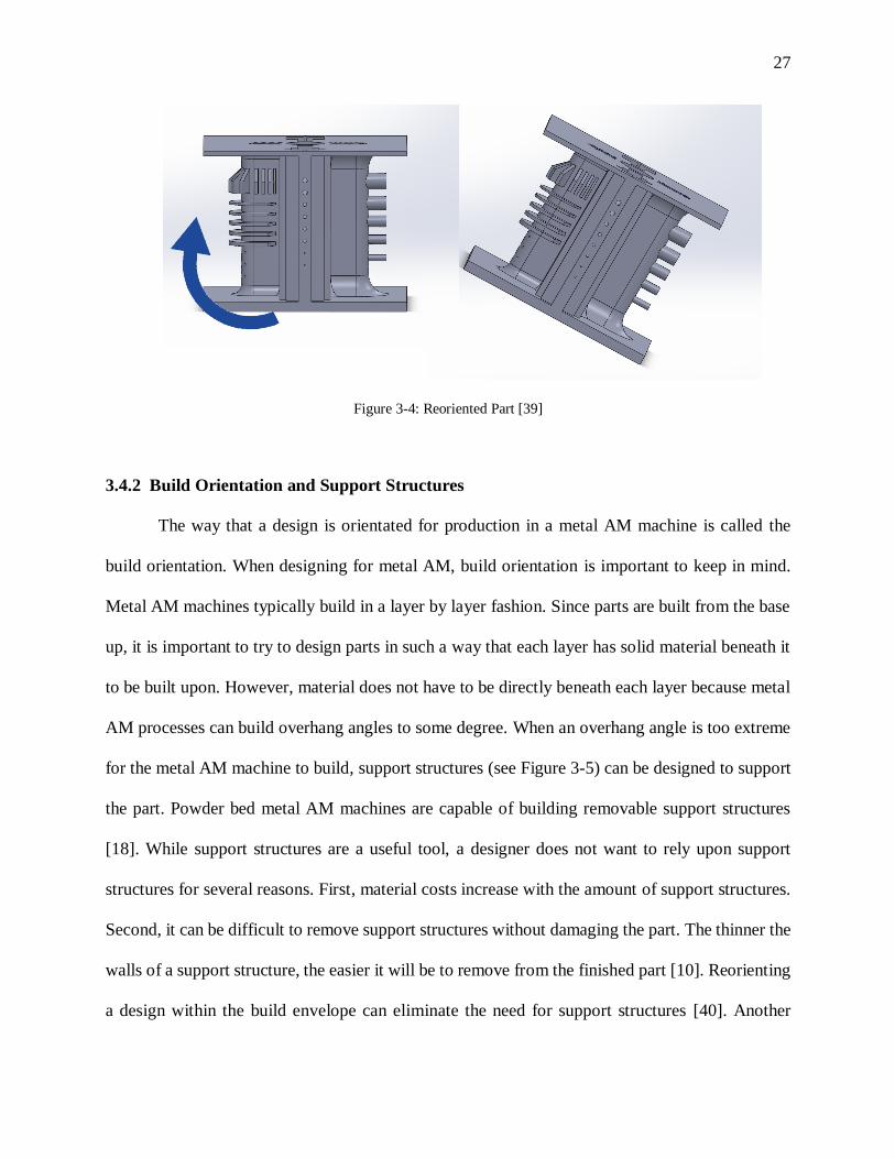
envelope for the EOS M 280 is 250mm x 250mm x 289mm [18]. Sometimes a part can be re-
oriented (see Figure 3-4) in order to fit in the build envelope; however, the designer must consider
potential changes to the part in order to build it in its new orientation [30].
Figure 3-3: Build Envelope
Page 35
27
Figure 3-4: Reoriented Part [39]
3.4.2 Build Orientation and Support Structures
The way that a design is orientated for production in a metal AM machine is called the
build orientation. When designing for metal AM, build orientation is important to keep in mind.
Metal AM machines typically build in a layer by layer fashion. Since parts are built from the base
up, it is important to try to design parts in such a way that each layer has solid material beneath it
to be built upon. However, material does not have to be directly beneath each layer because metal
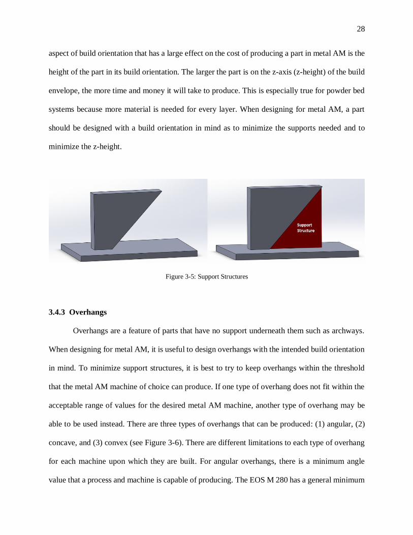
AM processes can build overhang angles to some degree. When an overhang angle is too extreme
for the metal AM machine to build, support structures (see Figure 3-5) can be designed to support
the part. Powder bed metal AM machines are capable of building removable support structures
[18]. While support structures are a useful tool, a designer does not want to rely upon support
structures for several reasons. First, material costs increase with the amount of support structures.
Second, it can be difficult to remove support structures without damaging the part. The thinner the
walls of a support structure, the easier it will be to remove from the finished part [10]. Reorienting
a design within the build envelope can eliminate the need for support structures [40]. Another
Page 36
28
aspect of build orientation that has a large effect on the cost of producing a part in metal AM is the
height of the part in its build orientation. The larger the part is on the z-axis (z-height) of the build
envelope, the more time and money it will take to produce. This is especially true for powder bed
systems because more material is needed for every layer. When designing for metal AM, a part
should be designed with a build orientation in mind as to minimize the supports needed and to
minimize the z-height.
Figure 3-5: Support Structures
3.4.3 Overhangs
Overhangs are a feature of parts that have no support underneath them such as archways.
When designing for metal AM, it is useful to design overhangs with the intended build orientation
in mind. To minimize support structures, it is best to try to keep overhangs within the threshold
that the metal AM machine of choice can produce. If one type of overhang does not fit within the
acceptable range of values for the desired metal AM machine, another type of overhang may be
able to be used instead. There are three types of overhangs that can be produced: (1) angular, (2)
concave, and (3) convex (see Figure 3-6). There are different limitations to each type of overhang
for each machine upon which they are built. For angular overhangs, there is a minimum angle
value that a process and machine is capable of producing. The EOS M 280 has a general minimum
Page 37
29
value of 35° [40]. So long as the overhang remains above that minimum angle, chamfers can be
produced in any orientation. For concave and convex overhangs, the radius is the limiting value.
Since a completely convex or concave overhang (one that completes 90° of a circle) will be less
than the minimum overhang angle either at the base or the tip, they are difficult to build at large
sizes. Therefore the smaller the radius, the better the concave or convex overhang is produced. For
concave overhangs in particular, the tip of the overhang is the most difficult to build as it has the
least amount of support underneath it. To prevent the overhang from failing, if reorienting the
design is not a possibility, then support structures are recommended. If reorienting the design is a
possibility, then the design should be oriented so that the amount of down-facing surface is reduced
as much as possible [41].
Figure 3-6: Overhangs
3.4.4 Tolerances
Tolerances are a measure of how much the part may vary from the designed dimensions.
It is important to consider the tolerance of a part when designing it for metal AM because different
metal AM machines have different dimensional accuracies and resolution. If the resolution of a
Page 38
30
machine is too large to get the tolerance for a part, then the part may not be dimensionally accurate
when finished. In cases where design tolerance is very important, such as connection points
between parts, it is recommended to add extra material to that section of the part, to be removed
via post-process machining [42]. The tolerances for the EOS M 280 machine range from 0.05mm
to 0.125 mm depending upon size [10].
3.4.5 Surface Finish
Different metal AM machines can make different surface finishes. The surface finish is
also likely to vary between build materials. Typically, the best surface finish on a part appears on
up-facing surfaces and the worst on down-facing surfaces (see Figure 3-7). Up-facing surfaces are
surfaces that are on the top of the parts orientation when it is built. Up-facing surfaces (see Figure
3-7) that are directly parallel to the substrate will have the highest quality surface finish [41]. The
closer that the up-facing surface is to parallel with the substrate, the better the surface finish will
be. If it is important that an up-facing surface is as accurate beyond the capability of the AM
machine, add material to it for post-process removal. Since the metal AM is typically a layer-by-
layer process, angled or curved up-facing surfaces (not parallel to the substrate) may have a
staircase stepping pattern (see Figure 3-7). The height of each step is directly linked to the layer
thickness produced by the metal AM machine. The same is true for angled or curved down-facing
surfaces as well. Down-facing surfaces are surfaces which are facing the substrate the part is built
on. Down-facing surfaces are typically overhangs. The reason that down-facing surfaces have
lower quality surface finishes is that they are built without solid material beneath them to stabilize
them during the build process. This also causes down-facing surfaces (especially parallel to the
substrate) to become slightly convex. This can be combatted by building the extremes of those
Page 39
31
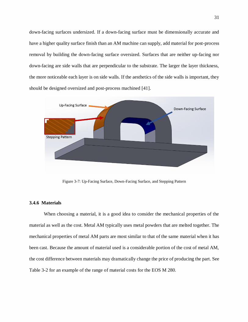
down-facing surfaces undersized. If a down-facing surface must be dimensionally accurate and
have a higher quality surface finish than an AM machine can supply, add material for post-process
removal by building the down-facing surface oversized. Surfaces that are neither up-facing nor
down-facing are side walls that are perpendicular to the substrate. The larger the layer thickness,
the more noticeable each layer is on side walls. If the aesthetics of the side walls is important, they
should be designed oversized and post-process machined [41].
Figure 3-7: Up-Facing Surface, Down-Facing Surface, and Stepping Pattern
3.4.6 Materials
When choosing a material, it is a good idea to consider the mechanical properties of the
material as well as the cost. Metal AM typically uses metal powders that are melted together. The
mechanical properties of metal AM parts are most similar to that of the same material when it has
been cast. Because the amount of material used is a considerable portion of the cost of metal AM,
the cost difference between materials may dramatically change the price of producing the part. See
Table 3-2 for an example of the range of material costs for the EOS M 280.
Page 40
32
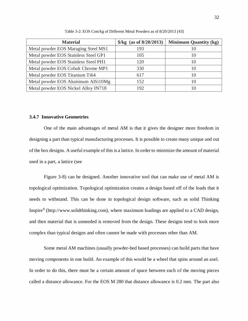
Table 3-2: EOS Cost/kg of Different Metal Powders as of 8/20/2013 [43]
Material $/kg (as of 8/20/2013) Minimum Quantity (kg)
Metal powder EOS Maraging Steel MS1 193 10
Metal powder EOS Stainless Steel GP1 105 10
Metal powder EOS Stainless Steel PH1 120 10
Metal powder EOS Cobalt Chrome MP1 330 10
Metal powder EOS Titanium Ti64 617 10
Metal powder EOS Aluminum AlSi10Mg 152 10
Metal powder EOS Nickel Alloy IN718 192 10
3.4.7 Innovative Geometries
One of the main advantages of metal AM is that it gives the designer more freedom in
designing a part than typical manufacturing processes. It is possible to create many unique and out
of the box designs. A useful example of this is a lattice. In order to minimize the amount of material
used in a part, a lattice (see
Figure 3-8) can be designed. Another innovative tool that can make use of metal AM is
topological optimization. Topological optimization creates a design based off of the loads that it
needs to withstand. This can be done in topological design software, such as solid Thinking
Inspire® (http://www.solidthinking.com), where maximum loadings are applied to a CAD design,
and then material that is unneeded is removed from the design. These designs tend to look more
complex than typical designs and often cannot be made with processes other than AM.
Some metal AM machines (usually powder-bed based processes) can build parts that have
moving components in one build. An example of this would be a wheel that spins around an axel.
In order to do this, there must be a certain amount of space between each of the moving pieces
called a distance allowance. For the EOS M 280 that distance allowance is 0.2 mm. The part also
Page 41
33
must be oriented in such a way that the machine can handle building no material between the
moving pieces. For the EOS M 280, the part must be oriented so the plane between the moving
components is between 30° and 35° from the substrate.
Figure 3-8: Lattice Structure
3.4.8 Holes
When designing holes in a part for metal AM, one must keep many things in mind.
Depending on the resolution of the metal AM machine, there is a limit to the smallest hole diameter
than can be built vertically (see Figure 3-9). The smallest recommended vertical hole diameter for
the EOS M 280 is 0.5 mm [40]. There are also limits to the minimum and maximum hole diameters
that go horizontally (see Figure 3-9) or on an angle through the part. For the EOS M 280 the
acceptable range of circular horizontal hole diameters is from 0.5mm to 6mm without support
structures. These limits exist because any hole that goes horizontally through a part is making a
complete overhang that may not be able to be self-supporting. There are ways to overcome this
however. If the holes do not need to be circular, then they can be designed as a self-supporting tear
drop shape (see Figure 3-9). The shape of self-supporting holes allow them not to need supports.
Another advantage of not designing circular holes is that circular holes have a tendency to shrink
Page 42
34
during the build process. Metal AM allows the designer to make holes in many types of self-
supporting shapes other than just circles. It also allows designers to make holes or irregular
passageways (see Figure 3-9) that are not just straight through a design, but take different routes.
Figure 3-9: Vertical, Horizontal, Irregular Path, and Self-Supporting Holes
3.4.9 Interior Features (Cavities)
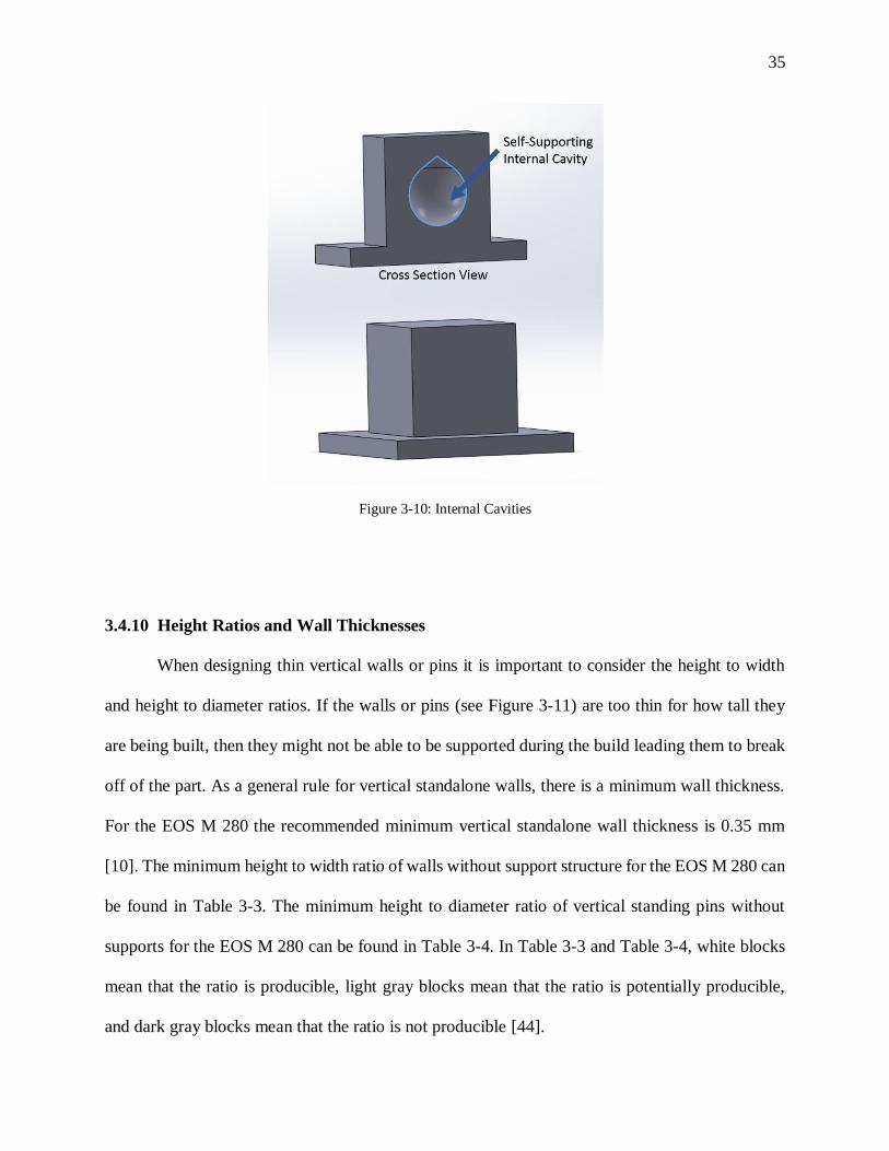
Along with different shaped holes, some metal AM processes allow for the creation of
interior features or cavities. Cavities are chambers within a part in which there is no solid
material. To optimally design cavities for metal AM, it is best to try to design it with self-
supporting shapes (see Figure 3-10). If the cavities need support structures, then it is often
impossible to remove them with post-processing. To create internal cavities without supports,
powder bed metal AM processes must be used. For removal of non-melted powder, post-built,
holes leading from the internal cavity to the exterior of the design should be designed. If they
are not, post-process machining can be done to remove the powder.
Page 43
35
Figure 3-10: Internal Cavities
3.4.10 Height Ratios and Wall Thicknesses
When designing thin vertical walls or pins it is important to consider the height to width
and height to diameter ratios. If the walls or pins (see Figure 3-11) are too thin for how tall they
are being built, then they might not be able to be supported during the build leading them to break
off of the part. As a general rule for vertical standalone walls, there is a minimum wall thickness.
For the EOS M 280 the recommended minimum vertical standalone wall thickness is 0.35 mm
[10]. The minimum height to width ratio of walls without support structure for the EOS M 280 can
be found in Table 3-3. The minimum height to diameter ratio of vertical standing pins without
supports for the EOS M 280 can be found in Table 3-4. In Table 3-3 and Table 3-4, white blocks
mean that the ratio is producible, light gray blocks mean that the ratio is potentially producible,
and dark gray blocks mean that the ratio is not producible [44].
Page 44
36
Figure 3-11: Height Ratios
Table 3-3: Height to Width Ratio [44]
Table 3-4: Height to Diameter Ratio [44]
Page 45
37
3.4.11 Minimum Feature Size
Since metal AM machines have different resolutions, each machine can only create features
that are as small as or larger than their minimum feature sizes. Features that are made smaller than
the minimum feature size cannot be built. The minimum feature size is determined by the layer
thickness as well as the contour width of the metal AM machine. These also determine the
minimum distance between features. For the EOS M 280 the minimum feature size is 0.2 mm. The
minimum distance between features for the EOS M 280 is also 0.2 mm [40].
3.5 Summary
To aid designers’ understanding of the capabilities and limits of the metal AM process, this
chapter proposed and compiled a set of design guidelines for metal AM (specifically for the EOS
M 280 machine) based upon design features. To generate these guidelines, the chapter first
examined the process of how a design becomes a finished part in metal AM to understand the
limitations of the metal AM process. Then design feature categories were compiled to and
examined for their dependencies on machine, material, and orientation. These design feature
categories were then expanded into design guidelines with a specific focus on the EOS M 280
powder bed machine. The design guidelines are made to be expanded upon by adding values for
individual rules for other machines and the materials that are available for those machines. Chapter
4 makes use of the design guidelines from this chapter in the development of a prototype metal
AM process selection tool that recommends a process by comparing feature values of a design to
the design guidelines.
Page 46
38
Chapter 4
AM Process Selection
4.1 Introduction
Although the guidelines for metal AM developed in Chapter 3 provide insight into what to
avoid while designing a part to be made with these techniques, it does not help a designer determine
which type of metal AM process to select to make their part. There are also designers that may
have already designed a part without knowing about the design guidelines and need feedback on
what changes, if any, need to be made to their design to utilize a metal AM process.
In order help a designer (experienced or new to metal AM) choose a method and receive
feedback on their design, a process selection tool has been developed that incorporates design
guidelines that help distinguish metal AM machines from each other, based on suggestions in the
literature [5]. This chapter takes a closer look at the structure and logic of the AM process selection
tool and how it was developed. The program is then examined to show how the logic is displayed
in the AM process selection tool and two designs are evaluated as examples for the AM process
selection tool.
4.2 Determining Process Selection Inputs and Outputs
In order to create an AM process selection tool by following recommendations from the
literature [5], we must first determine the desired output. In this case, the desired output is enough
information to give the designer an idea of which metal AM process to select to build a part. Since
metal AM is new to many designers, we also need to include in the output any changes that need
Page 47
39
to be made to the designers’ part to make it producible by an AM machine. The output should also
list all of the designers input so that the designer can compare their input to any of the suggested
changes in the output. Now that we have a desired output, we can determine what inputs are
necessary. The outputs as well as the inputs and their sources can be found in Figure 4-1.
Figure 4-1 Inputs and Outputs of Process Selection Tool
The inputs for the process selection tool are:
1) The support material from the design guidelines
2) The range of acceptable values for each feature asked about for each metal AM process
3) Values for the features of the designed part
Page 48
40
The designer inputs (3) are gathered by asking questions about individual design feature
values. Support material (1), in the form of example images and explanations, are provided to aid
in answering the questions. The designer inputs (3) are compared to the capabilities of each process
(2) to determine if there exists a machine that is applicable to the design, or if the design needs
changes to be applicable for the AM machines.
The process selection tool will then output the AM processes in order of most to least
applicable for the design, including what design features may have been outside the acceptable
ranges for each process. All of the information that the user inputs is also recorded in the output
report for the user to be able to compare their feature values to the features that were flagged as
out of the bounds of the machines’ capabilities. This enables the user to modify their designs for
the process that they may select. It also provides the designer with knowledge of the capabilities
of each metal AM process. This helps the designer to learn about design guidelines for metal AM.
In order to develop the logic that will allow us to use these inputs to generate these outputs,
we examine the list of design features and their values for each process and determine which should
be asked. A question for every design feature listed could be asked, however, that will result in
asking unnecessary questions and wasting the users’ time. Therefore, we need to determine which
features to ask about.
Determining which features to ask a designer about a part already designed requires
comparing the limitations of each machine with regards to their features. The features whose range
of acceptable values have the biggest difference between machines are the features that will
differentiate one process from another; however, some of these features may not be all that
common. Therefore we also need to examine which features are commonly used in parts that are
Page 49
41
planned to be produced with metal AM. To do this, parts that had been submitted to be built with
metal AM technology to ARL and Penn State’s CIMP-3D lab as well as other AM potential parts
were analyzed. The parts feature values were compared against the three metal AM machines that
CIMP-3D currently has: (1) EOS M 280, (2) LENS MR-7, and (3) Sciaky E-Beam. The feature
values were analyzed to see if they lay within the bounds for each machine. Failures were recorded,
i.e., when feature values were outside of the bounds for a machine. As more parts were analyzed,
the list of features was edited, adding and subtracting different features. One stage in determining
which features to ask about is shown as an example. Figure 4-2 through Figure 4-11 show the
features that were analyzed at that stage in process. The part shown was designed by Andrew
Coward [39].
Figure 4-2: Smallest Hole Diameter Parallel to Substrate [39]
Page 50
42
Figure 4-3: Largest Hole Diameter Parallel to Substrate [39]
Figure 4-4: Smallest Overhang Angle [39]
Figure 4-5: Smallest Wall Thickness [39]
Page 51
43
Figure 4-6: Smallest Distance between Features [39]
Figure 4-7: Smallest Hole Diameter Perpendicular to Substrate [39]
Figure 4-8: Smallest Radius of Curvature [39]
Page 52
44
Figure 4-9: Height to Diameter Ratio [39]
Figure 4-10: Height to Width Ratio [39]
Figure 4-11: Minimum Overhang Radius [39]
Page 53
45
After examining many sample parts and receiving feedback from metal AM machine
operators at CIMP-3D [45], a final set of questions was established (see Table 4-1). The questions
in Table 4-1 have been iteratively refined for process selection, clarity, and speed.
Table 4-1: Finalized List of Process Selection Features
Feature Number Feature
1 Units of .STL file
2 Material
3 Part Quantity
4 Recycled or new material
5 Maximum X dimension
6 Maximum Y dimension
7 Maximum Z dimension
8 Volume
9 Post-process machining
10 Largest hole parallel to substrate
11 Smallest hole parallel to substrate
12 Smallest hole perpendicular to substrate
13 Smallest distance between features
14 Smallest vertical standalone wall thickness
15 Smallest unsupported overhang
16 Largest concave overhang radius
17 Largest convex overhang radius
18 Internal cavities
4.3 Ranking System
With the features for process selection finalized, a ranking system can be developed for the
process selection tool. Originally, it was thought that the process tool should eliminate a process
whenever a value outside of its boundaries for a feature is inputted. However, given the creative
nature of additive manufacturing’s design freedoms, eliminating a process for one failed feature is
deemed to be too strict. The method of single elimination is abandoned and a more liberal method
Page 54
46
of scoring is instated. Whenever the design’s feature value is within the bounds of a metal AM
process, positive points are added to that process’ score. When the design’s feature value is outside
of an AM machines, negative points are added to the score. However, all features are equal.
Since failing to be within the bounds of one feature is not always the same as failing for
another feature, a few weighting methods were put in place. If a design is to be made with a
material that one metal AM machine does not support, then its score should be reduced by a much
greater amount than having an overhang angle that is 1° smaller than the minimum boundary of
the machine. In the cases such as these, feature weighting takes its effect. Failing in material will
result in -10,000 points being added to the score, while failing in the overhang angle will result in
-10 points being added. In this way, selecting a material that is not available for a machine will
essentially eliminate it when compared to a process that can use that material. Another method of
weighted scoring of feature values is by having a gradient scoring for failure. This means that
having an overhang angle 1° smaller than the minimum boundary of the machine will not have its
score diminished as much as an overhang angle 15° smaller than the minimum boundary of the
machine. The farther the design features value is below the minimum value of a process, the more
points that will be taken away from its score.
Table 4-2 illustrates the algorithm used to determine the score that a process receives based
on whether or not the process has the capability to produce that type of feature, if the user indicates
the design has that feature, and if the user indicated design feature value is within the boundaries
of the process. Table 4-3 illustrates the scoring system for whether or not the design fits within the
build envelope of a process and whether or not the process can build with the selected material.
The failure of either of these two criteria essentially eliminate a process from selection because the
process would be unable to produce the design.
Page 55
47
Table 4-2: Scoring Algorithm for Design Features
Process Capable
of Creating
Feature
Design
Feature
Value Input
Design Feature Value
within Process
Bounds Scoring
No Yes - Score = -100
No No - Score = 10
Yes Yes Yes Score = 10
Yes Yes
No (Greater than
Process Bounds)
Score = (Process Feature Value - Input
Design Feature Value)/2
Yes Yes
No (Less than Process
Bounds)
Score = (Input Design Feature Value -
Process Feature Value)/2
Yes No - Score = 10
Table 4-3: Scoring Algorithm for Material and Build Envelope
If Scoring
Process is capable of building with selected material Score = 10
Process is not capable of building with selected material Score = -10,000
Design fits within build envelope of process Score = 10
Design does not fit within build envelope of process Score = -10,000
4.4 Logical Flow
Now that the ranking system has been developed, the flow of logic can be examined. The
logical flow of the selection tool is important as it defines the manner in which the entire program
will run. It also determines the type of output and feedback that is given to the designer, which
needs to be useful. The tool’s logic is developed to ask a question to determine the value of every
feature and compare the values against all of the AM processes values one at a time. This means
that when a question is answered, its value is compared against all of the different supported metal
AM processes. Along with the question, a description of the feature and its importance (and in
some cases an image of an example part) is provided to the users to help them answer the query.
This description and example are derived from the design guidelines developed in Chapter 3. The
Page 56
48
range of acceptable values for each machine also comes from the design guidelines, but for that
specific machine.
Each process is then given its own score for that value. If a feature value is out of bounds
for a specific machine and receives a negative score for that value, then a flag is generated. A flag
informs the user what features that specific process was unable to make and why. Flags are listed
in the final output provided to the user. The logic then proceeds to ask the rest of the questions,
scoring and flagging each process as necessary until all of the queries have been asked. Finally,
the processes are listed in order of highest to lowest score, with all of flags listed under their
respective processes. All of the users input values are also listed in the output so that the user can
compare their values to any flags that their part may have gotten. This logic is illustrated in Figure
4-12.
Page 57
49
Figure 4-12: Process Selection Tool Logic Flow
Page 58
50
The one exception to this logical flow is the group of queries about the maximum X, Y,
and Z dimensions of the part. The goal of these queries is to determine if the design will fit in the
build envelope of the machine. However, we cannot just compare the maximum dimensions of the
part to the dimensions of the machines build envelope and say that if X dimension of part > X
dimension of machine, then the part does not fit. This is because it is possible that the design could
be able to fit in the build envelope in a different orientation. Thus, an algorithm is needed to
determine if the part can fit into the build envelope at any orientation. An algorithm to determine
an orientation that an object can fit into a bounding box [26] was modified for the use of
determining if a part will fit in the build envelope of an AM machine.
The developed algorithm creates a box that represents its maximum dimensions of the part,
and centers it within an AM machines build envelope. It then rotates the part box one degree at a
time (each time along a different axis) and at each rotation checks to see if the part box is contained
within the build envelope. If the part box is contained, then the part can fit in that specific AM
process. If not, the algorithm continues to rotate the part box until all possible orientations are
checked. If no orientation exists where the part box is contained within the build envelope, then
the part cannot fit in that specific AM processes build envelope. The build envelope, part box, and
rotation axes for this algorithm are illustrated in Figure 4-13.
Page 59
51
Figure 4-13: Reorientation Algorithm
For the maximum dimensions queries, the algorithm outputs whether or not the part fits in
the build envelope of the AM process. If the part fits, a positive score is given to that AM process
and if not, a negative score is given. This is done with simple if/then heuristics. The rest of the
queries for the process selection tool can just compare the designs feature value to the AM process
range and assign a score as described initially.
4.5 Development of a Process Selection Tool
With the logic developed, the next step is to implement it in software for automation. To
program the process selection tool, an expert system software was chosen: Exsys Corvid [46]. The
software was chosen for its many capabilities in simplifying the development of expert systems
Page 60
52
and its ability to add more processes to the process selection tool easily. The desired output of the
Exsys Corvid software is a Java applet, which is deployable on the Internet. This section describes
the process of the programming the process selection tool in Exsys Corvid and illustrates the user
interface of the developed Java applet AM process selection tool.
The Exsys Corvid software allows for variables to be created with prompts to ask the end
user to define a value for the variable. The user can select from a predefined list of values in the
form of a drop down menu or multiple choice options. The user can also input a numeric value. In
this manner we can create a variable for each design feature and ask the user to define its value.
Along with a prompt, Exsys Corvid also gives the option to link a variable to other text as well as
images. Using this capability we can provide a description and example image of each feature.
Once all the variables have been created, the next step is to determine how to compare the
values that the user defines to the range of acceptable values for each AM process. Fortunately,
Exsys Corvid provides the ability to import a spreadsheet of processes against their range of
acceptable values as what it calls a metablock (refer to Appendix B). Since Exsys Corvid relies
upon if/then statements for its logic, we can compare mathematically. This can be done by creating
if-statements such as “if the minimum overhang angle < the AM processes minimum overhang
angle.” Utilizing if-statements such as these, so that all possible answers are covered, allows us to
compare the user input to the metablock data. Then-statements can now be made following the if-
statements. Then-statements occur when an if statement is true and can assign values to variables,
record flags for failed queries, as well as adjust the score for each metal AM process that is being
compared. An example of a full if/then statement is: “If the minimum overhang angle < the AM
processes minimum overhang angle, then subtract 10 from the score for this process and add a flag
for this query to this processes output.”
Page 61
53
Using this programing format, the logic from Section 4.2 is implemented in the Exsys
Corvid software to create a results page for the process selection tool. The results page includes
the supported metal AM processes listed in ranked order from highest to lowest score, individual
flags that may have occurred for each process, and the user input. All of these features and logic
are wrapped together in Exsys Corvid, which then outputs a functioning Java outlet. The graphical
user interface (GUI) for each question is shown in Figure 4-14 through Figure 4-26.
Figure 4-14: Process Selection Tool GUI- General Questions
Page 62
54
Figure 4-15: Process Selection Tool GUI- Build Envelope Questions
Figure 4-16: Process Selection Tool GUI- Post-Process Machining Question
Page 63
55
Figure 4-17: Process Selection Tool GUI- Largest Horizontal Hole Diameter Question
Figure 4-18: Process Selection Tool GUI- Smallest Horizontal Hole Diameter Question
Page 64
56
Figure 4-19: Process Selection Tool GUI- Largest Vertical Hole Diameter Question
Figure 4-20: Process Selection Tool GUI- Smallest Distance Between Features Question
Page 65
57
Figure 4-21: Process Selection Tool GUI- Smallest Wall Thickness Question
Figure 4-22: Process Selection Tool GUI- Smallest Unsupported Overhang Question
Page 66
58
Figure 4-23: Process Selection Tool GUI- Largest Concave Overhang Radius Question
Figure 4-24: Process Selection Tool GUI- Largest Convex Overhang Radius Question
Page 67
59
Figure 4-25: Process Selection Tool GUI- Internal Cavities Question
Figure 4-26: Process Selection Tool GUI- Internal Cavities Accessibility Question
Page 68
60
4.6 Examples Parts
In order to illustrate how this AM process selection tool functions, sample parts that would
be made using AM are evaluated with the process selection tool. Two example parts are evaluated
the process selection tool for demonstration. The format that is used to show each parts flow
through the tool is a table of the queries and values that a designer would input for those queries.
Images that illustrate the feature that determines the designer’s input values are also given.
4.6.1 Example Part 1
The first example part is a turbine blade test part (see Figure 4-33) that was created for a
senior design project at The Pennsylvania State University to be built using CIMP-3D’s metal AM
processes. Table 4-4 details the values that are input by the user for the first example part. Figure
4-27 through Figure 4-30 show the features that define the user input from Table 4-4. Figure 4-31
and Figure 4-32 show the output of the process selection tool for example part 1. The output of the
process selection tool lists the recommended metal AM processes in order from highest score to
lowest. The tool recommended that the EOS M 280 powder bed fusion process be selected for
producing this design. However, one feature was flagged for the EOS M 280: the smallest hole
diameter perpendicular to the substrate. This would be an easy modification for the designer as the
designer would simply need to increase the hole diameter slightly and then no flags would exist
for EOS machine. Before the process selection tool was developed, the part was actually built on
the EOS M 280 machine (see Figure 4-33). The hole diameter that is flagged by the tool was filled
in with material by the EOS process. Had the designer used the process selection tool, the design
would have been modified and built 100% successfully.
Page 69
61
Table 4-4: Process Selection Tool Example Part 1 Input
Feature Designer Input
Units of .STL file mm
Material Inconel 718
Part quantity 1
Recycled or new material New
Maximum X dimension 16.75644 mm
Maximum Y dimension 32.04257 mm
Maximum Z dimension 25.4 mm
Volume 3601.91 mm3
Post-process machining No
Largest hole parallel to substrate 0.90254 mm
Smallest hole parallel to substrate 0.2 mm
Smallest hole perpendicular to substrate 0.2 mm
Smallest distance between features 0.65 mm
Smallest vertical standalone wall thickness 0.43 mm
Smallest unsupported overhang 69°
Largest concave overhang radius N/A
Largest convex overhang radius N/A
Internal cavities N/A
Figure 4-27: Maximum Axes Dimensions
Page 70
62
Figure 4-28: Minimum Hole Perpendicular to Substrate and Minimum/Maximum Hole Parallel to Substrate
Figure 4-29: Smallest Wall Thickness and Minimum Distance Between Features
Figure 4-30: Minimum Overhang Angle Cross-Sectional View
Page 71
63
Figure 4-31: Process Selection Tool Example 1 Output 1
Page 72
64
Figure 4-32: Process Selection Tool Example 1 Output 2
Page 73
65
Figure 4-33: Process Selection Tool Example 1 Built on EOS M 280
4.6.2 Example Part 2
The second example part is designed to showcase a different benefit to metal AM
processes. Typically AM is chosen as a process when designing a part with complex geometry;
however, metal AM also has the benefit of using less material than subtractive processes, which is
especially important when designing large parts with expensive materials such as titanium.
Example part 2 is designed in the fashion of a large AM part that would typically be produced with
a metal AM process to reduce material costs (see Figure 4-34). Table 4-5 details the values that
are input by the user for the second example part. Figure 4-34 through Figure 4-37 show the
features that define the user input from Table 4-5 and the output of the process selection tool for
example part 2.
Hole not fully produced
Page 74
66
Table 4-5: Process Selection Tool Example Part 2 Input
Feature Designer Input
Units of .STL file mm
Material Ti-6Al-4V
Part quantity 1
Recycled or new material New
Maximum X dimension 505 mm
Maximum Y dimension 455 mm
Maximum Z dimension 175 mm
Volume 7715201 mm3
Post-process machining Yes
Largest hole parallel to substrate N/A
Smallest hole parallel to substrate N/A
Smallest hole perpendicular to substrate 52 mm
Smallest distance between features 10 mm
Smallest vertical standalone wall thickness 8 mm
Smallest unsupported overhang N/A
Largest concave overhang radius N/A
Largest convex overhang radius N/A
Internal cavities N/A
Figure 4-34: Maximum Axes Dimensions
Page 75
67
Figure 4-35: Minimum Wall Thickness, Smallest Perpendicular Hole, Smallest Distance Between Features
Figure 4-36: Process Selection Tool Example 2 Output 1
Page 76
68
Figure 4-37: Process Selection Tool Example 2 Output 2
Page 77
69
4.7 Summary
To aid designers in the selection of a metal AM process for producing a design, this
chapter describes the development of a prototype metal AM process selection tool. First the
necessary inputs and outputs were determined following suggestions in the literature [5]. It was
determined that the process selection tool would operate by comparing feature values of the
users’ designs to design guideline limitations. Then the iterative method for determining which
features to use in process selection was described, and an example of an iteration was provided.
The method for ranking processes and the if/then heuristic logical flow of the process selection
tool was described and illustrated in a flow chart. The process of developing the process
selection tool using the Exsys Corvid software package was described and the graphical user
interface of the prototype was illustrated. Finally, two designs were evaluated as examples for
the prototype of the AM process selection tool.
Page 78
70
Chapter 5
Conclusions and Future Work
Ever since the “buzz” about 3D printing in social media created by President Obama’s
State of the Union Address [1], industry and academia have been focusing much of their attention
on developing AM. Additive manufacturing has the potential to create near net-shaped parts that
typical manufacturing processes are unable to do. This research has described design features that
can be used to analyze the capabilities of metal additive manufacturing processes, the compilation
and creation of design guidelines for metal AM, and the development of a tool for process
selection.
The flow from CAD file to a final built part was discussed, explaining the complexity of
the decision making that occurs during this work flow. With the complexity understood, design
features were categorized and described based upon build dependencies on (1) machine, (2)
material, and (3) orientation. An example on orientation dependency was provided to demonstrate
the importance of these dependencies. These design features were also organized into categories
based upon similarity of the features to facilitate understanding and simplify work flow for
designers reading the guidelines. The importance of these categories and features, in relation to
design for AM, was then discussed. The features were then expanded into design rules, which were
given values for the EOS M 280 machine. It was then explained that these design guidelines need
to be compiled for all AM machines and presented in a similar format for designers to have easy
access to them.
The need for increasing user understanding was addressed, and an automated process
selection tool was proposed. The process selection tool was described as being based upon the
Page 79
71
design guidelines for metal AM, allowing the tool to perform its primary function, as well as acting
as a teaching tool for designers.
The inputs and outputs of the process selection tool were then defined. The iterative process
in which design features, that the process selection tool would be based upon, were selected was
then discussed. An example of that iterative process was given to demonstrate the decision making
process. The final design guidelines that were used for the process selection tool were then listed
in a table. The method for scoring the processes was established. The if/then heuristic logic based
on questions about the part design was then examined and a flowchart describing it was generated.
The layout of process selection tool was described and a prototype of the actual tool was developed
using Exsys Corvid software. Figures of all possible steps the tool makes were then shown in order
to detail how information and questions would be presented to the user. Finally, two parts were
put through the process selection tool as an example and to demonstrate operation of the tool.
Figures illustrating how the designers would enter the necessary information to use the process
selection tool from CAD software were shared. After each part was put through the process
selection tool, the outputs were generated and shown as figures. The output was shown to detail
how the designers would utilize it to inform them of changes that may need to be made to their
designs as well as to know which process was most suited to their design.
In the future, research in this field should be developed to ensure that industries understand
AM and utilize it appropriately in the production of their products. This includes the developing,
gathering and sharing of design guidelines and feature values for industries machines. This
information should be gathered for new processes and machines as they are developed. With this
information compiled and readily accessible to designers, designs will be developed in a manner
that lends itself to additive manufacturing’s capabilities. With designs being streamlined for metal
Page 80
72
AM processes, the time and iteration that can occur in the information exchange between designers
and machine operators can be dramatically reduced.
Future work on the process selection tool consists of a more formal scoring system, user
testing for intuitiveness, and evaluating the AM process selection tool as a teaching tool. Future
research needs to be conducted in feature recognition of CAD designs. If feature recognition and
part analysis can be automated, then the process selection tool can be redesigned to simulate each
AM process, outputting how the final part would look to the designer, as well as build time and
cost estimation.
In order to utilize metal additive manufacturing technology to its upmost potential,
designers and engineers need to fully understand the capabilities and limitations of the process. If
more designers understand how to use the AM process, then more advanced parts can be developed
and the technology will grow and its capabilities increase. This goal can be attained through the
distribution and expansion of the design guidelines for metal additive manufacturing processes.
The process selection tool can be a powerful method for spreading design guidelines. As progress
continues to advance this technology, we come closer to the day that our creations are only limited
by our imaginations.
Page 81
73
REFERENCES
[1] S. Kurutz, "The New York Time," 20 February 2013. [Online]. Available:
http://www.nytimes.com/2013/02/21/garden/the-3-d-printer-may-be-the-home-appliance-of-the-
future.html?pagewanted=all&_r=0.
[2] J. Scott, N. Gupta, C. Weber, S. Newsome, T. Wohlers and T. Caffrey, Additive Manufacturing:
Status and Opportunities, Science and Technology Policy Institute, 2012.
[3] D. Rosen, "ASTM WK38342," 14 7 2012. [Online]. [Accessed 9 4 2013].
[4] D. Rosen, I. Gibson and B. Stucker, Additive Manufacturing Technologies, New York, Springer,
2010.
[5] D. Rosen and I. Gibson, "Chapter 4: Decision Support and System Selection for RP," in
Software Solutions for RP, London, UK, Professional Engineering Publishing, 2002, pp. 317-
388.
[6] J. B. Beaman, D. L. Bourell, M. C. Leu and D. W. Rosen, A Breif History of Additive
Manufacturing and the 2009 Roadmap for Additive Manufacturing: Looking Back and Loocking
Ahead, RapidTech: US-Turkey Workshops on Rapid Technologies, 2009.
[7] J. E. Blanther, "Manufacture of Contour Relief Maps". US Patent 473901, 1892.
[8] G. N. Levy, R. Schindel and J. P. Kruth, "Rapid Manufacturing and Rapid Tooling with Layer
Manufacturing (LM) Technologies," CIRP Annals- Manufacturing Technology, no. 52.2, pp.
589-609, 2003.
[9] C. Atwood, M. Ensz, D. Greene, M. Griffith, L. Harwell, D. Reckaway, T. Romero, E.
Schlienger and J. Smugeresky, "Laser Engineered Net Shaping (LENS(TM)): A Tool for Direct
Fabrication of Metal Parts," Sandia National Laboratories, Livermore, CA, 1998.
[10] 3DPARTS Manufacturing LLC, "EOS M 280- Direct Metal Laser-Sintering," 3DPARTS
Manufacturing LLC, 2013. [Online]. Available: http://www.3dpartsmfg.com/eos-m280-dmls.
[Accessed 14 2 2014].
[11] W. M. Johnson, "Benchmarking Evaluation of an Open Source Fused Deposition Modeling
Additive Manufacturing Solution," Austin, TX, Solid Freeform Fabrication Symposium, 2007,
pp. 197-211.
[12] A. Bowyer, "RepRap," 13 October 2013. [Online]. Available: http://reprap.org/wiki/RepRap.
Page 82
74
[13] J. P. Kruth, M. Leu and T. Nakagawa, "Progress in Additive Manufacturing and Rapid
Prototyping," CIRP Annals- Manufacturing Technology, no. 47.2, pp. 525-540, 1998.
[14] M. Fahad and N. Hopkinson, "A New Benchmarking Part for Evaluating the Accuracy and
Repeatability of Additive Manufacturing (AM) Processes," 2nd International Congress on
Mechanical Production and Automobile Engineering (ICMPAE'2012), pp. 234-238, 2012.
[15] I. Gibson, G. Goenka, R. Narasimhan and N. Bhat, "Design Rules for Additive Manufacture,"
2010. [Online]. Available:
http://utwired.engr.utexas.edu/lff/symposium/proceedingsArchive/pubs/Manuscripts/2010/2010-
59-Gibson.pdf. [Accessed 6 February 2014].
[16] J. B. Beaman, D. L. Bourell, M. C. Leu and D. W. Rosen, Roadmap for Additive
Manufacturing: Identifying the Future of Freeform Processing, University of Texas, Austin,
TX, 2009.
[17] S. Shipp, N. Gupta, B. Lal, J. A. Scott, C. L. Weber, M. S. Finnin, M. Blake, S. Newsome and
S. Thomas, Emerging Global Trends in Advanced Manufacturing, Institute for Defense
Analyses, Alexandria, VA, 2012.
[18] EOS, "Laser Sintering System - EOSINT M 280 Data Sheet," [Online]. Available:
http://www.eos.info/systems_solutions/metal/systems_equipment/eosint_m280. [Accessed 30
March 2014].
[19] Optomec, "LENS MR-7 System Manual," 2009. [Online]. Available:
http://www.optomec.com/Additive-Manufacturing-Downloads/Product-Datasheets. [Accessed
30 March 2014].
[20] D. M. Keicher, J. E. Smugeresky, J. A. Romero, M. L. Griffith and L. D. Harwell, "Using the
Layer Engineered Net Shaping (LENS) Process to Produce Complec Componenets from a CAD
Solid Model," Proc. of SPIE, 1997, pp. 91-97.
[21] Sciaky Inc, Direct Manufacturing Specifications, [Online]. Available:
http://www.sciaky.com/additive_manufacturing.html. Chicago, IL, 2011.
[22] D. W. Rosen, "Design for Additive Manufacturing: A method to Explore Unexplored Regions
of the Design Space," Austin, Texas, Solid Freeform Fabrication Symposium, 2007, pp. 402-
415.
[23] R. Ponche, J. Y. Hascoet, O. Kerbrat and P. Mognol, "A new global approach to design for
additive manufacturing," Virtual and Physical Prototyping, vol. 7, no. 2, pp. 93-105, 2012.
Page 83
75
[24] J. G. Bralla, in Design for Manufacturability Handbook, 2nd Edition, New York, NY, The
McGraw-Hill Companies, Inc., 1999, pp. 422-706.
[25] H. Ford, in My Life and Work, New York, NY, Doubleday, Page & Company, 1922, pp. 141-
156.
[26] C.-K. Chan, "Minimum bounding boxes and volume decomposition of CAD models," PhD
Dissertation, The University of Hong Kong, Pokfulam, Hong Kong, 2003.
[27] DFMPro A Geometric Product, "DFMPro for Machining," 2014. [Online]. Available:
http://dfmpro.geometricglobal.com/processes/dfmpro-for-machining/. [Accessed 5 April 2014].
[28] ExOne, "What is Additive Manufacturing," 2012. [Online]. Available:
www.exone.com/sites/default/files/media/ExOne_What_is_AM.pdf. [Accessed 30 March
2014].
[29] S. Khoo, "The Star Tech News," 22 November 2013. [Online]. Available:
http://www.thestar.com.my/Tech/Tech-News/2013/11/22/3D-printing-for-everyone.aspx/.
[Accessed 6 February 2014].
[30] E. Chernow, M. Samperi, T. W. Simpson, S. Joshi and R. Martukanitz, "A Process Planning
Framework for LENS Metal Additive Manufacturing," in Proceedings of the 2013 Industrial
and Systems Engineering Research Conference, 7 pages, 2013.
[31] Wohlers Associates, "Manufacturers and Developers of Additive Systems and Materials,"
Wohlers Associates, 2013. [Online]. Available: http://wohlersassociates.com/manufacturers-
and-developers.html. [Accessed 24 March 2014].
[32] T. Wohlers, Wohlers Report 2007, State of the Industry Annual Worldwide Progress Report,
Wohlers Associates Inc, Fort Collins, CO, 2007.
[33] A. Palmer, "The Design and Development of an Additive Fabrication Process and Material
Selection Tool," University of Central Florida, Orlando, Florida, 2009.
[34] P. Zelinski, "Modern Machine Shop," 4 April 2013. [Online]. Available:
http://www.mmsonline.com/articles/how-additive-manufacturing-is-like-cnc-machining-and-
how-its-very-different. [Accessed 24 March 2014].
[35] Solid Concepts, "SLS Design Guidelines," 2 September 2013. [Online]. Available:
http://www.so lidco ncepts.co m/reso urces/dg/selective-laser-sintering-sls-design-guidelines/.
Page 84
76
[36] M. T. Samperi, E. Chernow, T. Simpson, S. Joshi and M. Talbot, "Towards a Process Worklow
for Designing and Fabricating Parts Using Additive Manufacturing," in RAPID, Pittsburgh, PA,
10 pages, 2013.
[37] NetFabb, "3D Printing Made Easy," netFabb, [Online]. Available: http://www.netfabb.com/.
[Accessed 24 March 2014].
[38] Materialise, "Software for Additive Manufacturing," Materialise, 2014. [Online]. Available:
http://software.materialise.com/magics. [Accessed 24 March 2014].
[39] A. Coward, Test Build Part, The Pennsylvannia State University, University Park, PA, 2013.
[40] M. Ayre, "Prezi," 7 11 2012. [Online]. Available: https://prezi.com/login/?next=/4gnoki3-
ieyu/saving-dmls-design-guidelines-v2/. [Accessed 9 4 2013].
[41] D. Thomas, "The Development of Design Rules for Selective Laser Sintering," MS. Thesis,
Loughborough University, Loughborough, UK, 2009.
[42] 3D Systems, "Quickparts," 3D Systems, 12 1 2013. [Online]. Available:
http://www.quickparts.com/eu/en.aspx. [Accessed 15 2 2014].
[43] C. Dickman, EOS Powder Metal Costs. [Interview]. 27 March 2014.
[44] EOS, "EOS e-Manufacturing Solutions," 17 2 2004. [Online]. Available:
http://www.eos.info/additive_manufacturing. [Accessed 12 8 2013].
[45] R. Martukanitz, C. Dickman, K. Meinert and E. Reutzel, Process Selection Tool Feedback
Meetings. [Interview]. October 2013.
[46] Exsys, "Exsys Corvid (version 5.4)," 2013. [Online]. Available:
http://www.exsys.com/index.html. [Accessed 30 March 2014].
[47] D. Rosen, Additive Manufacturing Technologies: Radpid Prototyping to Direct Digitial
Manufacturing, New York, NY: Springer, 2010.
[48] GE, "Design guide," 1997. [Online]. Available: www.manterra.com/GE_Design_Guide.pdf.
[Accessed 30 March 2014].
[49] M. Ghazy, "Development of an Additive Manufacturing Decision Support System (AMDSS),"
Newcastle University, UK, 2012.
Page 85
77
[50] Badge Machine Products, Inc., "Design for Manufacturability (DFM)," 2013. [Online].
Available: http://www.badgemachine.com/dfm.htm. [Accessed 5 April 2014].
[51] T.-C. Chang, R. A. Wysk and H.-P. Wang, "Design for Manufacturing- Guidelines," in
Computer-Aided Manufacturing, Second Edition, Prentice Hall, 1998, pp. 596-598.
Page 86
78
APPENDIX A
Design Guidelines for Metal AM Comprehensive List
Feature
Number
Feature Rule
Number
Rules
1 Support Structures 1 Minimum overhang for support structures
1 Support Structures 2 Only powder bed metal AM processes
can build support structures
1 Support structures 3 Support structures need to be removed
and therefore must be accessible
2 Surface Quality 4 Minimum overhang angle for acceptable
surface quality
2 Surface Quality 5 Optimum orientation for best surface
quality
3 Up-Facing Surfaces 6 45° up-facing surfaces degrade until they
suddenly improve at 0°
3 Up-Facing Surfaces 7 Up-facing surfaces will be built
dimensionally accurate
3 Up-Facing Surfaces 8 Add material to an up-facing surface to be
post-process machine to create a flat
surface
4 Down-Facing Surfaces 9 Material should be added to down-facing
surfaces as there is no solid material
underneath it
4 Down-Facing Surfaces 10 The extremes of down-facing surfaces can
be undersized
4 Down-Facing Surfaces 11 Support structures do not reduce the
amount of oversized material on down-
facing surfaces
4 Down-Facing Surfaces 12 Down-facing surfaces can become convex
due to stress from gravity during build
5 Side Walls 13 Side walls will be built flat
5 Side Walls 14 Material can be added to side walls for
improved aesthetics
6 Distance Between
Features
15 The minimum distance between features
7 Wall Thickness 16 The minimum wall thickness
8 Concave Overhang Radii 17 The maximum concave overhang radius
8 Concave Overhang Radii 18 To design a concave tangential overhang
radius to build accurately and
successfully, the amount of down-facing
overhang on the curve needs to be
reduced by decreasing the tangent at the
highest position of the curve
Page 87
79
8 Concave Overhang Radii 19 Supports will prevent concave overhang
radii from curling upwards
9 Convex Overhang Radii 20 The maximum convex overhang radius
9 Convex Overhang Radii 21 To design a convex tangential overhang
radius to build accurately and
successfully, the amount of down-facing
overhang on the curve needs to be
reduced by decreasing the tangent at the
highest position of the curve
9 Convex Overhang Radii 22 Supports will prevent convex overhang
radii from curling upwards
10 Overhang Angle 23 The minimum overhang angle buildable
without support structures
11 Complex Curves 24 Complex curves that are both concave ad
convex follow the rules for concave and
convex overhang radii for applicable
sections
12 Hole Parallel to Substrate 25 Minimum hole diameter parallel to the
substrate
12 Hole Parallel to Substrate 26 Maximum hole size parallel to the
substrate without supports
13 Hole Perpendicular to
Substrate
27 Minimum hole diameter perpendicular to
the substrate
13 Hole Perpendicular to
Substrate
28 Any hole size can be built without
support but might require post-process
removal
14 Hole Shape 29 If holes are not required to be circular,
they can be made in any shape
15 Self-Supporting Holes 30 Self-supporting holes can be designed in a
teardrop shape
15 Self-Supporting Holes 31 Self-supporting holes can be designed in a
diamond shape or any other shape with
overhang angles above the minimum
overhang angle
16 Edges 32 Unless a sharp edge is absolutely
necessary, radii or chamfers are more
dimensionally accurate
16 Edges 33 Chamfers can be built in any orientation
above the minimum overhang angle
16 Edges 34 The minimum radius of curvature
17 Drafts 35 Drafts should be designed around
minimum wall thickness
18 Build Envelope 36 The maximum build envelope of the
machine
Page 88
80
18 Build Envelope 37 The part can be reoriented to fit in the
build envelope of the machine
19 Layer Thickness 38 The minimum layer thickness of the
machine
20 Threads 39 Threads should be built according to the
minimum overhang angle
21 Internal Cavities 40 Some machines cannot built internal
cavities
21 Internal Cavities 41 The minimum wall thickness for the
creation of internal cavities
21 Internal Cavities 42 Internal cavities need to be made
accessible for post process material
removal
22 Minimum Feature 43 The minimum feature size
23 Height Ratios 44 The minimum height to diameter ratio for
pins
23 Height Ratios 45 The minimum height to width ratio for
rectangular builds
23 Height Ratios 46 The minimum height ratios for thin walls
24 Moving Components 47 Some machines can build connected
moving components can be made in a
single build
24 Moving Components 48 The planes between 2 moving
components should be 30° from the
substrate
24 Moving Components 49 The necessary distance between moving
parts so they do not merge in the build
process
25 Complex Geometries 50 Complex geometries such as lattices can
be built to reduce material while maintain
structural stability
26 Tolerances 51 For parts that need exact dimensions,
material can be added for post process
machining
26 Tolerances 52 Round holes tend to shrink
26 Tolerances 53 Machine dimensional tolerances
Appendix A Design Guidelines for Metal AM Comprehensive List
Page 89
81
APPENDIX B
Metablock
Appendix B Metablock