Page 1
Development of Electronic Voting Machine with the Inclusion of Near Field
Communication ID Cards, Biometric Fingerprint Sensor and POS Printer
Supervisor: Dr. Md. Khalilur Rhaman
Conducted by:
Arafa Mohd. Anis (10201010)
Hamidur Rahman (11121106)
Jennifer Sherry Alam (11321039)
Sohel Islam Nabil (11121108)
Syed Mahmud Hasan(11101029)
School of Engineering and Computer Science
BRAC University
Submitted on:
28th December 2014
Page 2
2
DECLARATION
This is to certify that that this thesis report is submitted by the authors listed for the degree of
Bachelor of Science in Computer Science and Engineering and Bachelor of Science in Electrical
and Electronic Engineering to the Department of Computer Science and Engineering and
Department of Electrical and Electronic Engineering under the School of Engineering and
Computer Science, BRAC University. We hereby declare that this thesis is based on the results
found by us and no other. Materials of work found by other researchers are mentioned by
reference. This thesis, neither in whole nor in part, has been previously submitted for any
degree.
Signature of Supervisor Signature of Author
________________________ ________________________
Dr. Md. Khalilur Rhaman Arafa Mohd. Anis
________________________
Hamidur Rahman
________________________
Jennifer Sherry Alam
________________________
Sohel Islam Nabil
________________________
Syed Mahmud Hassan
Page 3
3
ACKNOWLEDGEMENTS
We would like to start by expressing our gratitude to our supervisor Dr. Md. Khalilur Rhaman,
Acting Chairperson and Associate Professor, Department of Computer Science and Engineering,
BRAC University for encouraging and supporting us through the development of this project.
We thank Dr. S. M. Lutful Kabir, Visiting Professor, for his valuable advice that helped guide the
thesis in the right direction. It would have been extremely difficult to complete our work
without the help of Risul Karim, we thank him for taking time out of his busy schedule to lend
us his expertise. We would like to highlight the immense help provided by Md. Zahangir Alom
and M Abdur Rahman Adnan for our work. Lastly, we are grateful to our peers, Ismail Kiron and
Omar Khan for giving us their lending hands in our project.
Page 4
4
ABSTRACT
The basis of this project is to create an electronic voting machine that will help to eradicate
defrauding of the manual voting systems and prior versions of electronic voting. The thesis
looks into and proposes a system that includes multiple layers of verifications to ensure the
reliability of the device. With the inclusion of Near Field Communication ID cards and biometric
fingerprint sensor, each voter is entered into the system through a swift process only after
being recognized and checked with the given database of enlisted voters. Once the
corresponding fingerprint is matched with the information provided by the identification card,
the voter will be allowed to proceed to choosing their preferred candidate from the panel of
buttons. Respective cards and fingerprints are marked for future references. The final vote is
then printed out onto a ballot for the satisfaction of voters. The proposed project displays
transparency and also carries the feature of being autonomous during the course of operation.
Keywords: EVM, NFC, fingerprint, POS printer, Arduino, Raspberry Pi
Page 5
5
TABLE OF CONTENTS
Declaration ............................................................................................................. 2
Acknowledgement .................................................................................................. 3
Abstract .................................................................................................................. 4
List of Figures .......................................................................................................... 6
Chapter 1 Introduction ........................................................................................ 9
1.1 Motivation ......................................................................................................... 9
1.2 Thesis Outline ......................................................................................... 10
Chapter 2 Background Study ............................................................................. 11
2.1 Voting System in Bangladesh .......................................................................... 11
2.2 Literature Review .................................................................................... 12
Chapter 3 System Architecture.......................................................................... 15
3.1 System Overview ............................................................................................ 15
3.2 Devices ............................................................................................................ 16
3.3 Sequence Diagram .......................................................................................... 17
Chapter 4 System Implementation .................................................................... 18
4.1 Interfacing of Devices ..................................................................................... 19
4.2 System Integration .......................................................................................... 22
4.2.1 Development of database .................................................................... 23
4.2.2 Integration of Raspberry Pi and Arduino.............................................. 23
4.3 System Power Supply ...................................................................................... 24
4.4 Obtaining Results from Votes ......................................................................... 28
Page 6
6
Chapter 5 Experimental Results and Discussion ................................................ 30
Chapter 6 Conclusion ........................................................................................ 38
6.1 Limitations ....................................................................................................... 38
6.2 Future Works .................................................................................................. 38
6.3 Conclusion ....................................................................................................... 40
References ............................................................................................................ 42
Appendices ........................................................................................................... 44
Page 7
7
LIST OF FIGURES
Code Title Page
Figure 3.1 Internal Devices and Connections ..................................................... 15
Figure 3.2 Sequence of System Flow ................................................................. 17
Figure 3.3 Sequence of Information Flow .......................................................... 17
Figure 4.1 Internal Connections ......................................................................... 19
Figure 4.2 Flowchart of Information .................................................................. 22
Figure 4.3 Importing Information from Arduino to Raspberry Pi ....................... 23
Figure 4.4 Sending Information to Arduino from Raspberry Pi .......................... 24
Figure 4.5 Series Connection of Batterries ......................................................... 24
Figure 4.6 Schematic Diagram of Voltage Regulators ........................................ 25
Figure 4.7 Schematic Diagram of 9V Voltage RegulatorSwtiches ....................... 25
Figure 4.8 Schematic Diagram of Swtiches ........................................................ 26
Figure 4.9 Table of Readings for Voltage and Current Obtained ........................ 27
Figure 5.1 Example of Printed ID card ............................................................... 29
Figure 5.2 Experimental System ........................................................................ 30
Figure 5.3 Graph of Confidence Level versus Number of Trials .......................... 31
Figure 5.4 Feedbacks after Presenting NFC ID card ........................................... 32
Page 8
8
Figure 5.5 Finger Placed on Fingerprint Sensor ................................................. 33
Figure 5.6 Feedbacks after NFC ID card Matches Fingerprint ............................ 33
Figure 5.7 Feedbacks after Vote Casting ............................................................ 34
Figure 5.8 Printing of Ballot ............................................................................... 35
Figure 5.9 Display Output .................................................................................. 36
Figure 5.10 Complete System .............................................................................. 36
Page 9
9
CHAPTER 1
INTRODUCTION
Voting is the fundamental right in any democracy; it expresses the choice of the people and
upholds the very meaning of a system governed by the people’s choice. However, the methods
used to represent these votes have become debatable issues. Throughout history different
techniques of voting have evolved; from simple hand written paper ballots to internet voting
systems that simply require voters to log in from the comfort of their homes to cast their choice
from their personal computers. Though procedures are numerous, a proper voting system
through which the public are comfortable in trusting is yet to be proposed. Each system has
come to showcase its own version and variation of issues. This has caused an agitation amongst
voters and it is ever more important to implement technology in this endeavor.
1.1 Motivation
The soliciting of votes is not an uncommon one in both different eras of history and diverse
geographical locations. Most recently the elections of 2014 in Bangladesh provided a huge
challenge on the country and its people. Unfair means were believed to be in use and the main
opposition leader refused to participate in the elections, thus causing a chaos to pursue in the
country. Continuous chains of strikes continued which affected all sectors of people’s lives. The
economy suffered, and the people suffered. The parliamentary votes of 2014 saw merely a
51.37% voter turn-out according to the Institute for Democracy and Electoral Assistance [1].
Half of the candidates were unchallenged and people felt deprived of their voting rights [2]. Yet
a simple solution seemed to be applicable to all these problems; if a proper voting system
existed, on which no one could point fingers at would have clearly thrown off any party that
would have tried to utilize it otherwise. Not only in Bangladesh, but in countries such as the
USA, Australia and India have also seen their fair share of turmoil due to unreliable voting
systems. A study conducted estimates a total of two to four million lost votes in the presidential
elections of 2000 [3]. Thus, the need for a reliable and fraud proof voting system is dire one to
Page 10
10
safeguard the interest of the general public in any nation. In this era of technology, it seems
only evident that voting systems of the past are upgraded to one that serves the real purpose
of allowing people to vote.
1.2 Thesis Outline
Chapter-2 shows a study of the current system utilized in the voting procedure of Bangladesh
and includes the background study and literature review of related work which was used to
develop the project.
Chapter-3 describes the system design of the thesis, details of devices incorporated and
diagrams of how each was brought together to form the complete system is provided.
Chapter-4 includes in depth procedure for the implementation of the machine, including the
techniques used for interfacing all the devices and power supply to the machine.
Chapter-5 reviews the results found through the research and provides a discussion on the
findings.
Chapter-6 specified the limitations of the machine, provides the future works that may be
approached and conclusion.
Page 11
11
CHAPTER 2
BACKGROUND STUDY
To understand the areas which need to be focused on in order to develop a sustainable
electronic voting machine it is important to first comprehend the existing voting systems and
identify the flaws within it. The background study allows us to break down the aspects that
have caused falter and the potential triumphant features to put within the new system.
2.1 Voting System in Bangladesh
The current voting process followed in Bangladesh includes verifying of voters by polling agents
through a distributed list to match the information on each voter’s ID card. The voter is allowed
to proceed into the polling booth when the information coincides with the ones provided list. A
major flaw in this process is subjected upon the sole reliance on the integrity of the polling
agent. A voter may be allowed to enter into the voting procedure more than once through the
manipulation of the agents responsible for overlooking this procedure. Another fraudulent
activity may occur if someone manages to take more than their allocated number of ballot
papers. Since ballots are counted manually, a person using the same ID card in different polls
may be able to give multiple votes. This occurrence has been observed during many elections in
Bangladesh.
To distinguish voters who have already casted their vote the polling agent is responsible to
mark one of the fingers of the voter with ink. This ink mark can be removed through vigorous
washing and thus is not a very reliable source of identification. The same individual may
proceed to cast another vote by going to a different polling station. One of the most reported
Page 12
12
cases of vote tampering is when ballot boxes go missing during elections; boxes may be stolen
during the time of transit from the voting booths to their ultimate destination.
Mentioned above are some of the obstacles that stand in the way of Bangladesh from having a
fair and transparent election. The corruption has reached such a level that it became crucial to
initiate a new voting process which would minimize such errors and fraud ensuring that the
public are not being deceived. In a true democracy, it’s the people’s fundamental right to
participate in an election not plagued by deceit.
2.2 Literature Review
The first ever vote in record took place in Rome in 139BC and used simple hand written paper
ballots. [3] This system was further modernized and the existing system was first used in
Australia in 1858. The system incorporated the use of a set of ballots that were provided by the
government. The ballots contained the list of candidates and voters showed their preference by
placing a mark on the provided area using pens, stamps and other specified markers. [5] The
voter received privacy to place their votes after which the paper ballot was returned and kept
in safeguard until the time of tally. [3] The tally is obtained from an accurate count, or so it is
supposed to be. This system is still widely used today around the world; however the threats
posed by the paper ballot system have been quite evident in many accounts. The most evident
of the issue was the controlling of the count of votes. On many occasions ballot papers are
found to have unclear markings that make it hard to distinguish the choice of the voter. These
give a wide range chance of the rigging of votes. The party in power may deliberately chose
counting teams so as to modify the outcome through the use of such circumstances. The 1910
Encyclopedia Britannica states in its information of voting machines that; up to forty percent of
votes were commonly nullified in the process of tallying. [3] Perhaps with the statistics in hand
most electronic voting machines suggested have completely eradicated the use of paper
ballots. However, as an age old method, it is one that voters can physically see and feel assured
Page 13
13
that they have actually indeed cast their vote. Therefore, we would like to propose the idea of
keeping this traditional system as a sort of back up and feel well system to the electronic parts
by the use of a POS printer to print out ballots.
Research found on ways an electronic voting system could be sustainable for Bangladesh
suggests that the system should integrate the following features [6]. The voting system should
maintain the privacy of voters, and should maintain that only enrolled voters are allowed to
cast their vote. Only one vote per voter should be maintained, there should not be an
opportunity for authorities to swindle the vote counts or choice, and there should not be any
receipt of the voting account. The system should also display transparency but be discrete in
the procedure, and finally it should be an accurate system that can withstand the usage of
multiple voters. However, these are requirements that can be related to the sustenance of a
voting system in any environment as suggested in [5]. An election system should be able to
withstand a variety of fraudulent behaviors and should be sufficiently transparent and
comprehensible that voters and candidates can accept the result of an election.
The major issue of traditional voting systems oscillates around the system of tallying. The main
problem of this system is dependable on manual procedure and for this reason has raised many
questions. Following the US presidential elections in 2000, questions rose on the ballot
counting procedure [7]. During the counting of tally, ballots may be displaced and often marks
on ballots are hard to identify and distinguish [7] [8]. Therefore we would like to simplify the
tedious job of tally counting with the help of modern technology. Keeping count of the tallies
should be digitalized, to save time and of course increase reliability. To eliminate the confusion
of distinguishing between improperly marked ballots we plan on using digital buttons systems.
The advantage being that pressing on the button means a vote has been casted and no chance
is left to human error.
As suggested by research, an election system should be able to withstand fraudulent behaviors
[5] [6]. This includes the familiar issue of multiple votes cast by a single voter. When a voter is
admitted into the system to cast their vote, it is essential that they are properly identified and
allowed to vote only once. Keeping this in mind, the paper suggests the use of Near Field
Page 14
14
Communication (NFC) cards as each voter’s identification tag. NFC technology allows for
communication between the users ID card and the device in a very fast and uncomplicated
manner and increases the usability [10]. However, only NFC cards as the main entry system of a
voting machine can make it susceptible to attacks [11]. Furthermore, using only an ID card
opens the opportunity for a voter to use different voter ID cards to cast multiple votes.
To overcome these complications and to reinforce the checking procedure, the paper suggests
the use of fingerprint identification using reliable biometric technologies. Use of biometrics in
voting systems has been an acclaimed one as fingerprints are unique to individuals [12]
[13].The system suggested uses the fingerprint of the voter to compare to a predetermined
database where the information on the voters NFC ID card must match to their corresponding
fingerprint. After the verification and matching of the two data, the voter is allowed to proceed
to voting. With the automation and use of two layers of identification systems, the procedure
removes the chance of any fraudulent entrants.
Many electronic voting systems that have been proposed before contain the use of online
networking, and the risk of tampering of information through hacking posed a great threat [7]
[9]. The machine presented eliminates the use of a live network altogether, thus causing the
vote casted to be safe from any tampering. Through the integration of these features and the
multiple checking mechanism of using NFC cards and biometric fingerprint identifier, a more
secure and prompt method of the traditional voting system can be developed which complies
with the expectations mentioned in [5] [6].
Page 15
15
CHAPTER 3
SYSTEM ARCHITECTURE
3.1 System Overview
The proposed system utilizes the NFC cards as an identification card for voters. Each voter ID
card contains a unique ID number and information on whether they have already cast a vote.
These IDs will be stored in the database with their corresponding fingerprints prior to the
voting process. Once the NFC shield identifies the ID provided, the respective fingerprint is
matched through the fingerprint sensor. If the two match, the voter is allowed to select their
choice of candidate from the buttons in the selection panel. Once a vote has been casted the
ID card is marked for future referencing, so as to prevent the voter from casting multiple votes.
The selected candidate’s logo is printed out on a ballot by the POS printer. The voter is also
marked in the database of the system. Each candidates vote is stored in the database, and once
the voting process has ended, the results may be obtained. To view the results of the vote, a
master card is made; when the ID card with the information of the master card is provided, the
display shows the list of candidates and their corresponding number of votes.
Figure 3.1: Internal Devices and Connections
Power Supply
NFC Controller
Shield
Fingerprint
Sensor
Arduino
UNO
Raspberry Pi
2.8” Display Selection
Buttons
POS Printer
Page 16
16
3.2 Devices
The devices utilized in the system are as follows:
1) NFC controller shield: Near Field Communication (NFC) cards interact with the NFC controller
shield via the use of electromagnetic radio fields. To allow two way communications between
the ID cards and the device the system uses a reader/writer shield. This allows the device to
both receive and send data to the ID cards coming into the range of operation. The NFC system
is valid for a 13.56 MHz frequency. The shield is connected to the Arduino UNO, and all data
received and sent through the shield are processed by the microcontroller.
2) Optical fingerprint sensor: The fingerprint sensor is also connected to the Arduino UNO. An
integrated DSP chip within the device processes the identification and matching of fingerprints.
Packets of data are sent each time a fingerprint is received, and each fingerprint is given a code
which is stored in the database.
3) 320X240 2.8” TFT touch screen display: The display is connected to the Raspberry Pi. The
microcontroller uses a graphical user interface to display information and instructions.
4) Arduino UNO: The Arduino UNO is an advanced open source microcontroller based on the
ATmega328. The main operation programs for the devices connected to it are stored within. It
is programmed using the Arduino software.
5) Raspberry Pi: The Raspberry Pi is a single board computer. The board allows the integration
of database, display and POS printer in this system.
6) POS printer: The POS printer is essentially a receipt printer which utilizes thermal paper for
the printing of images. Auto-cut ability allows the ballot to cut lose once the printing has
finished. The printed ballot falls through a transparent channel and into a ballot box
Page 17
17
3.3 Sequence Diagram
Figure 3.2 Sequence of System Flow
Figure 3.3 Sequence of Information Flow
Page 18
18
CHAPTER 4
SYSTEM IMPLEMENTATION
The integral system utilizes the different characteristics of each device essentially brought
together by the use of the microcontrollers, i.e. the Arduino UNO and Raspberry Pi. The process
of bringing the system together involves connecting each of the devices together into a
comprehensive system that allows for information to move about at ease from one device to
another, or from one end of the sequence to another.
Page 19
19
Figure 4.1 Internal Connections
4.1 Interfacing of Devices
To bring together the devices into the comprehensive system the devices must first be
interfaced with the microcontrollers in charge of directing them. In order to be able to direct
the applications of each device the following process was used for interfacing.
NFC Controller Shield:
Page 20
20
To evaluate and manipulate the NFC ID cards, the PN532 NCF controller shield from ElecFreaks
is used with the Arduino UNO. The shield compiles with the Arduino UNO, and the pins are
connected. The PN532 software library developed from Adafruits PN532 Library was used to
program the shield. As the NFC cards come with a unique identification number which was used
as the identification number for each voter, information carried within the card is kept discrete
by encapsulating, and the data can only be manipulated during the initial set up procedure. The
cards are blank at the primary stage and have to be initialized to be entered into the system.
Once the card is brought into the range of the shield, through the use of the serial monitor, the
information within it becomes available. To enroll a voter into the list, the corresponding
identification number of each card and individual is stored into the database. Registered voters
may proceed to voting only when they have placed their ID cards within the range of the NFC
shield. Once the card has been acknowledged by the device, it proceeds to check that the
identification number is present in the provided database. When this has complied the voter is
given a signal to move onto the next stage.
Fingerprint Sensor:
The fingerprint sensor from Adafruit is also interfaced with the Arduino UNO and is connected
to the microcontroller using the TTL serial. The interface library for Arduino from GitHub was
used to enroll and check different fingerprints. The enroll sketch is run to store the fingerprints
into the device. Through the serial monitor each finger entered into the system for each voter is
given an identification number. This number is stored into the database to the corresponding
voter’s identification number. During the process for checking the fingerprints, the serial
monitor displays a value for the confidence level when a match has been found. This value
shows how well the device is able to identify and match the fingerprint that has been placed.
When a fingerprint match has been found within the device, the enrolled number for the
fingerprint is checked with the database in the Raspberry Pi. The number obtained from the
sensor and the corresponding fingerprint number of the NFC card entered earlier is matched by
one to one checking. The comparison then yields a value for success that allows the voter to
proceed to vote.
Page 21
21
LCD Display:
Instructions and results are displayed through the use of the LCD display which is interfaced
with the Raspberry Pi. The voter’s picture and name are displayed when the information of the
voters ID card and fingerprint matches.
Voting Panel:
Vote is cast through the use of buttons corresponding to each candidate’s information. The
model produced consists of seven choices. The buttons are connected to the Arduino UNO
board and each line is stored in the database for the candidates in the election. Once a button
is pressed the candidates count is incremented and the voting process is stopped. No more
votes are accounted for after one vote. If a voter attempts to press the button multiple times,
or try to select any other button, the buzzer will ring. Subsequently, when a candidate’s count
has been incremented, the voter’s NFC identification card is encrypted to not allow any further
acceptance into the system. The database in the Raspberry Pi is also marked off.
POS Printer:
The POS printer is connected to the Raspberry Pi board. To install the printer into the Raspberry
Pi system first we must utilize Common Unix Printing System, CUPS. This allows the printers
driver to be installed onto the Raspberry Pi environment and the printer may be used through
prompts in the LXTerminal.
Page 22
22
4.2 System Integration
Utilizing the devices all together requires the integration of the total system. To do so, first a
database that the microcontrollers can refer to must be established. For the process to flow
seamlessly there must be an integration of the two microcontroller boards with each other.
Figure 4.2 Flowchart of Information
Page 23
23
4.2.1 Development of Database
Developing the database requires a memory space that can store the information provided.
Thus the memory card in the Raspberry Pi is utilized. In the project we have utilized a 16 GB
memory card with our Raspberry Pi. to create the database using MySQL, an open-source
relational database management system. Using Python to manipulate the database the
relations include Voter_id, Fingerprint_id, Name, and Picture of each enlisted voter. When an
ID card is presented to the NFC shield, the information is checked in the database to see
whether they are eligible to vote. To prove the voter is eligible, the corresponding
fingerprint_id is returned and the fingerprint sensor sends information about the users
fingerprint. A one to one matching is conducted with the fingerprint of the voter and the
corresponding fingerprint against the voter id in the database. If and when they match the user
can proceed to the voting panel.
4.2.2 Integration of Raspberry Pi and Arduino
The Arduino UNO and Raspberry Pi boards are connected together via the use of serial USB
cable. Through the use of pySerial, the Raspberry Pi is able to read from and write to serial port
using. We used Python Programming Language to code in this part of the system. The Arduino
software is available in compatible format which allows the Arduino programs to be run directly
from the command prompt of the Raspberry Pi atmosphere.
To integrate the system as a whole we need to communicate to and fro from the Arduinos and
Raspberry Pi. This is done by importing and sending information through the use of the port.
Page 24
24
import serial
ser = serial.Serial('/dev/ttyACM0', 9600)
Figure 4.3 Importing Information from Arduino to Raspberry Pi
The serial port name is found and through the USB interface name, messages and information
from the Arduino may be received.
ser.write('Information to Arduino')
Figure 4.4 Sending Information to Arduino from Raspberry Pi
To send information the serial write command is utilized in the pySerial.
4.3 System Power Supply
Supplying the power to the devices is done by the use of two 6V 4.5 AH batteries connected in
series, giving a total of 12 V and keeping the capacity of 4.5 AH. The total of 12V is supplied to
each of the devices according to their power ratings through the use of voltage regulators.
Figure 4.5 Series Connection of Batteries
Page 25
25
Figure 4.6 Schematic Diagram of Voltage Regulators
Figure 4.7 Schematic Diagram of 9V Voltage Regulator
The three 5V regulators are paralleled to maintain the current rating in the devices that are
attached. The 5V supply is given to run the Arduino UNO, Raspberry Pi, fingerprint sensor,
Page 26
26
ballot switches and connections to the printer. The 9V supply is provided to the cooling fan in
the system. C1, C4, C4 and C6 are used as bypass capacitors to help avoid extremely small
duration points with the ground so as to save distress of the other components. C2 and C5 are
used as filter capacitors which are employed to steady the slow changes in the voltage applied
at the input of the circuit.
Figure 4.8 Schematic Diagram of Switches
Page 27
27
The switches draw power parallel from the 5V regulator and when closed light an LED to show
the selection choice. They are connected to the Arduino through the use of an 8 to 3 encoder.
This allows simplification of the circuit as well as ease of communication for the Arduino to
identify the choice of the voter.
The power, efficiency and run time of the device was calculated as follows.
Figure 4.9 Table of Readings for Voltage and Current Obtained
Battery Capacity = 4.5AH
Average Currents
( ) ( ) 0.96A
( ) 0.12A
( ) ( )
Min MAX
12.19V
(Pi) 5.05V
(Dc Fan) 8.89V
1.12A 1.17A
(Pi) 0.87A 1.04A
(Dc Fan) 0.09A 0.14A
Page 28
28
Power Consumption
For Pi: ( ) ( )
For Dc fan: ( ) ( )
Total Power:
Calculating Efficiency
( ) ( )
( ) ( ) =
( ) ( )
( ) =
Total Efficiency:
Run time of the Device (Using Linear Regulators)
Time = Battery Capacity Load Current = 4.5AH 1.08A 4.17 hours
≈ 4hr 10 mins
The approximate run time of the machine is calculated to be 4 hours and 10 minutes. However,
the system utilizes a charging system that would allow the machine to be run directly from the
mains power supply. Switching on the device, the AC power supply is stepped down by a
transformer and rectified. The DC power received is supplied to charge the battery and so
supply the power for the devices.
Page 29
29
4.4 Obtaining Results from the Vote
Once the voting process has finished, the vote count can be obtained by using the master card.
The master card is yet another NFC ID card that can be given to authorities. The information of
the ID is set to trigger the Arduino to give back the count for votes of each candidate. This can
be further secured by having a time period in which this master card can only work.
Page 30
30
CHAPTER 5
EXPERIMENTAL RESULTS AND DISCUSSIONS
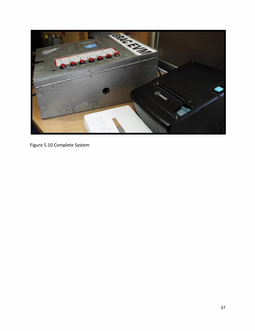
The total system was placed into a wooden box. The display, selection buttons, and fingerprint
sensor being visible from the top. The NFC shield is placed beneath the cover of the top and the
area where the NFC ID cards are to be placed is marked. The cover is connected to a hinge and
so can be flipped open to where the other circuitry is placed for repair and management.
To experiment the whole procedure of the EVM we have utilized six different NFC IDs as
prototype national voter ID cards. These ID cards were assigned to each person and their
corresponding information and fingerprint ID was entered into the system.
The process of entering an individual into the EVM system consists of running the program for
enrollment. The individual is provided first with an NFC ID card; the ID cards number is
identified and stored to the person’s name. Next the users fingerprint is recorded using the
fingerprint sensor, and an ID is given to the stored fingerprint. The fingerprint ID number is then
stored in the corresponding column of the individual in the database. A picture of the individual
is taken and stored from a memory slot and also saved in the database. The candidates for
votes were listed as Candidate 1, Candidate 2, etc. where the first button corresponds to
candidate 1 and so on.
Figure 5.1 Example of Printed ID Card
Page 31
31
Figure 5.2 Experimental System
To check the accuracy of the fingerprint device a total of twenty fingerprints were stored in the
fingerprint sensor. The confidence level received for the each of these fingerprints were
collected a total of five experimental trials. The average value of the confidence level received
was plotted against the number of trial. When plotted for the best line, a linear curve with
confidence level of higher than 100 was received. This shows good accuracy and the reliability
of the fingerprint sensor can be confirmed through this finding. The readings of the experiment
can be found in the appendix. During the course of this thesis work, the fingerprint device first
utilized was the fingerprint scanner TTL C1 using the Principal Component Analysis (PCA)
algorithm. However, the confidence level threshold obtained from the device was on an
average 50. Thus, the fingerprint sensor being utilized here shows a much more reliable and
efficient alternative to be used in the system.
Page 32
32
0 5 10 15 20 2550
100
150
200
250
300
350
Trial
Confidence L
evel
Figure 5.3 Graph of Confidence Level versus Number of Trials
The complete process of voting was carried out several times. Once the NFC ID Card is placed
near the shield the following feedback and prompt are given in the serial monitor of the
Arduino software when the information on the card matches one found in the database.
Page 33
33
Figure 5.4 Feedbacks after Presenting NFC ID card
Once the prompt to place fingerprint is given the fingerprint sensor lights up. The users
fingerprint is taken and checked to the corresponding information on the database and if a
match is found the buzzer makes a beep to direct the user to cast their vote. The user than can
proceed to voting.
Page 34
34
Figure 5.5 Finger Placed on Fingerprint Sensor
Figure 5.6 Feedbacks after NFC ID card Matches Fingerprint
Page 35
35
The voter is required to hold on to the button corresponding to their preferred candidate for a
few seconds and when the vote has been recorded the buzzer sounds another beep to confirm
the process. After the vote has been casted, the corresponding candidates vote is printed out as
the ballot.
Figure 5.7 Feedbacks after Vote Casting
Page 36
36
Figure 5.8 Printing of Ballot
After the voting procedure has finished, using the master card the count of the votes can be
seen on the screen.
Figure 5.9 Display Output
Page 37
37
Figure 5.10 Complete System
Page 38
38
CHAPTER 6
CONCLUSION
6.1 Limitations
The thesis includes the initial works done for the development of a system that aims to dictate
a much larger scale of the voting frontier. Thus the machine still has many limitations that need
to be overcome to allow it to reach the level it is aimed for.
Starting with the devices integrated in the machine, for large scale production and use the
devices need to be upgraded to better or alternate versions. The fingerprint sensor that was
previously used had a low threshold for the output confidence level and overall low efficiency,
and so the Adafruit fingerprint sensor is an improvement on those levels. However, the
fingerprint sensor used has a limit on the memory storage as the fingerprints obtained are
stored in its internal memory. A total of 256 fingerprints may be stored in the device, but for
large scale operations the device will be an obstacle.
Another obstacle arising from the fingerprint is the possible chance of a voter enrolling with
more than one fingerprint data. If by some circumstance the voter is able to provide more than
one fingerprint, then the voter would be able to enter the system more than once.
Interfacing between Arduino and Raspberry Pi using USB causes the connection to be
vulnerable to an external jammer. Jammers may scramble the data in the devices and thus
security questions may arise from the device.
6.2 Future Works
The future works related to the further development of the EVM centers around the upgrading
Page 39
39
of the devices and internal systems that overcome the limitations mentioned as well as make
the device a real modern solution to the problems faced.
The use of a fingerprint sensor that can be operated by an internally generated algorithm but
can use an external source of memory to store and identify the fingerprints should be found so
that there is no limit on the number of fingerprints stored. The current process only gives an
identification number for the fingerprint stored and the identification number is subsequently
stored in the database. Future aims are to establish a system where the findings of the
biometric sensor is stored directly and interacted from the database.
To overcome the possibilities of multiple fingerprints entered by one voter, the enrolling
procedure should be better defined. Only thumbprints of voters should be allowed to be
enlisted, for example. This would make sure that no other fingerprint is being stored with the ID
cards presented.
Encryption of all the devices should be given a priority. Since the device works autonomously,
the risk of networks being hacked have been eliminated. However to make the machine risk
free from jamming and other form of devices that may ruin the internal circuitry the devices
should be encoded and the casing should be made to bar these interferences.
The integration of a larger number selection buttons can be done by using more encoders. The
maximum number of buttons required on average by elections should be found and
incorporated. The Graphical User Interface or GUI needs to be further developed for a seamless
process. More fluid voting process may be established by using high efficiency buttons or by
using a touch screen display.
Page 40
40
6.3 Conclusion
The concept of electronic voting systems is not a new one. However for its use to widely spread
it is important to aim for a system that properly is able to fulfill all the requirements expected
as well as the standards achievable by the use of technology. The system provided by this paper
goes the lengths to cover the necessities that research has deemed a requirement for a fair,
transparent and reliable election tool.
Using NFC cards as the voters ID card allows each individual card to carry information that can
be used to match with solely its owner. It is also a simple and quick technology which only
requires the placement of the card in close proximity of the sensor. There is no hassle of having
to insert or place in accurate order, this not only increases usability but also makes the process
an efficient one. The second step of verifying the identification of an enrolled voter consists of
the fingerprint sensor. The obvious advantage of biometrics is that it cannot be altered or
copied. Each individuals fingerprint is matched and stored in the database to their
corresponding voter ID card. Through this process, the window of impersonation is nullified.
Furthermore, the NFC cards allow the voters to be marked of electronically once they have
casted a vote, thus removing the risk of one voter casting multiple votes.
To allow transparency with the user of the system, the printer provides a brief view of the
ballot that is printed out after the vote has been casted. The advantage of not handing out a
ballot to the user means that the voter is not able to manipulate or misplace the vote. Ballots
stored in the ballot box also means that the electronic tally of votes received by each candidate
can be cross checked with the count of paper ballots. Overall, the integrated system covers all
the major issues faced and ensures both voters and candidates a trusted means for elections.
Though the system works in multiple layers of verifications, areas of improvement is available.
The fingerprint sensor used in the project only has a limited number of fingerprint storage
Page 41
41
within the device, for large scaled elections a more suitable sensor should be replaced. The
printer used to print the ballots is not a complete auto-cut system. To further optimize the
device, preferably a customized printer that completely cuts the ballot and drops it precisely
into the ballot box should be aimed for.
Overall, the system shows a trend towards better performance of an electronic voting machine.
Through incorporations of numerous devices it can alleviate the satisfaction of all parties
involved in an election.
Page 42
42
REFERENCES
[1] http://www.idea.int/vt/countryview.cfm?CountryCode=BD
[2] http://www.nytimes.com/2014/01/07/world/asia/bangladeshi-premiers-party-wins-
election-amid-unrest.html?_r=0
[3] Voting: What Is; What Could Be, (2001, July). Available:
http://www.vote.caltech.edu/Reports/
[4] M. M. Sarker & M. N. Islam, “Management of Sustainable, Credible and Integrated
Electronic Voting (E-Voting) System For Bangladesh,” Management of Sustainable
Development, vol.5, no.1, pp.15-21, 2013.
[5] D.A. Kumar, T.U.S Begum, “A Novel design of Electronic Voting System Using Fingerprint,”
International Journal of Innovative Technology & Creative Engineering, vol.1, no.1, pp.12-19,
January 2011.
[6] D. A. Kumar & T. U. S. Begum, “A Comparative Study on Fingerprint Matching Algorithms for
EVM,” Journal of Computer Sciences and Applications, vol.1, no.4, pp. 55-60, 2013
[7] Mercuri, R. “A better ballot box?” IEEE SPECTRUM, vol.39,no.10,October, 2002.
[8] K.Y.Lian, S.J.Hsiao & W.T.Sung, “Mobile Monitoring and Embedded Control System for
Factory Environment,” Sensors, vol.13, no.12, pp.17379-17413, 2013
[9] B.T.MacIntosh, “Methods and arrangements for identifying objects,” U.S. Patent Application
13/946,968, July 19, 2013.
[10] A.Jacek, “New Methodology of Designing Inexpensive Hybrid Control-Acquisition
Systems for Mechatronic Constructions,” Sensors, vol.13, no.12, pp.17222-17240, 2013
[11] C. Edwards, “Not-so-humble raspberry pi gets big ideas,” Engineering & Technology, vol.
8, no.3, pp. 30-33, 2013
[12] I. J. Britz, Remote monitoring of a coffee percolator with a web-based platform using
sensors and an actuator (Doctoral dissertation, University of Stellenbosch), 2014
Page 43
43
[13] Rayner, J. (2013). Time to Kill the Paper Ballots? First, Let’s Look at the Alternatives.
Retrieved from http://theconversation.com/time-to-kill-paper-ballots-first-lets-look-at-the-
alternatives-19767
[14] Raspberry Pi. Retrieved from https://www.adafruit.com/category/105
Adafruit PN532 NFC/RFID Controller Shield for Arduino + Extras. Retrieved from
https://www.adafruit.com/products/789
[15] Adafruit Optical Fingerprint Sensor. (2014) Ladyada. Retrieved from
https://learn.adafruit.com/downloads/pdf/adafruit-optical-fingerprint-sensor.pdf
[16] Arduino Mega R3 Android Accessory Development Kit (ADK) Board. Retrieved from
http://www.adafruit.com/products/563
Page 44
44
APPENDICES
A. Table of readings of confidence level from fingerprint sensor
Confidence level
Trial No. Best Worst Average
1 329 188 258.5
2 157 56 106.5
3 156 110 133
4 199 110 154.5
5 102 54 78
6 120 67 93.5
7 191 132 161.5
8 107 64 85.5
9 60 51 55.5
10 237 105 171
11 134 67 100.5
12 86 52 69
13 245 168 206.5
Page 45
45
14 158 86 122
15 151 55 103
16 135 80 107.5
17 205 162 183.5
18 97 71 84
19 74 51 62.5
20 129 94 111.5
21 373 312 342.5
22 81 51 66
23 156 110 133
24 107 53 80
25 157 64 110.5
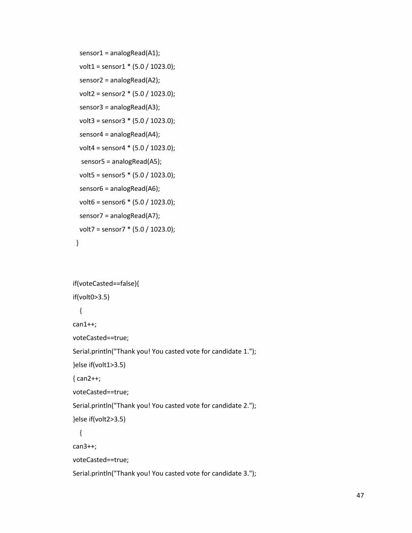
B. Sample code of vote counting process in the Arduino
//Check whether vote has already been cast using nfc card
int can1 = 0;
int can2 = 0;
int can3 = 0;
int can4 = 0;
int can5 = 0;
int can6 = 0;
int can7 = 0;
int can8 = 0;
Page 46
46
int sensor0 = 0;
int sensor1 = 0;
int sensor2 = 0;
int sensor3 = 0;
int sensor4 = 0;
int sensor5 = 0;
int sensor6 = 0;
int sensor7 = 0;
float volt0, volt1, volt2, volt3, volt4, volt5, volt6, volt7;
boolvoteCasted = false;
// the setup routine runs once when you press reset:
void setup() {
// initialize serial communication at 9600 bits per second:
Serial.begin(9600);
Serial.println("Cast your vote NOW! Press the button for 3 seconds");
}
// the loop routine runs over and over again forever:
void loop() {
//int can2,can3,can4,can5,can6,can7,can8;
// read the input on analog pin 0:
delay(5000);
// Convert the analog reading (which goes from 0 - 1023) to a voltage (0 - 5V):
if(voteCasted==false){
sensor0 = analogRead(A0);
volt0 = sensor0 * (5.0 / 1023.0);
Page 47
47
sensor1 = analogRead(A1);
volt1 = sensor1 * (5.0 / 1023.0);
sensor2 = analogRead(A2);
volt2 = sensor2 * (5.0 / 1023.0);
sensor3 = analogRead(A3);
volt3 = sensor3 * (5.0 / 1023.0);
sensor4 = analogRead(A4);
volt4 = sensor4 * (5.0 / 1023.0);
sensor5 = analogRead(A5);
volt5 = sensor5 * (5.0 / 1023.0);
sensor6 = analogRead(A6);
volt6 = sensor6 * (5.0 / 1023.0);
sensor7 = analogRead(A7);
volt7 = sensor7 * (5.0 / 1023.0);
}
if(voteCasted==false){
if(volt0>3.5)
{
can1++;
voteCasted==true;
Serial.println("Thank you! You casted vote for candidate 1.");
}else if(volt1>3.5)
{ can2++;
voteCasted==true;
Serial.println("Thank you! You casted vote for candidate 2.");
}else if(volt2>3.5)
{
can3++;
voteCasted==true;
Serial.println("Thank you! You casted vote for candidate 3.");
Page 48
48
}else if(volt3>3.5)
{
can4++;
voteCasted==true;
Serial.println("Thank you! You casted vote for candidate 4.");
}else if(volt4>3.5)
{
can5++;
voteCasted==true;
Serial.println("Thank you! You casted vote for candidate 5!");
}else if(volt5>3.5)
{
can6 ++;
voteCasted==true;
Serial.println("Thank you! You casted vote for candidate 6!");
}else if(volt6>3.5)
{
can7 ++;
voteCasted==true;
Serial.println("Thank you! You casted vote for candidate 7!");
}else if(volt7>3.5)
{
can8 ++;
voteCasted==true;
Serial.println("Thank you! You casted vote for candidate 8!");
}else{
Serial.println("You voted for no one!");
voteCasted==false;
Serial.println("Cast your vote again! Hold the button for 3 seconds!");
}
printVoteCount();
}
Page 49
49
delay(1000);
}
voidprintVoteCount(){
String c1 = "no. of votes for candidate 1: ";
Serial.println(c1 + can1);
String c2 = "no. of votes for candidate 2: ";
Serial.println(c2+ can2);
String c3 = "no. of votes for candidate 3: ";
Serial.println(c3+ can3);
String c4 = "no. of votes for candidate 4: ";
Serial.println(c4+ can4);
String c5 = "no. of votes for candidate 5: ";
Serial.println(c5+ can5);
String c6 = "no. of votes for candidate 6: ";
Serial.println(c6+ can6);
String c7 = "no. of votes for candidate 7: ";
Serial.println(c7+ can7);
String c8 = "no. of votes for candidate 8: ";
Serial.println(c8 + can8);
}