1 Development of high power window prototypes for ECH&CD launchers R. Heidinger* ,1a , I. Danilov 1a , A. Meier 1a , B. Piosczyk 1b , P. Späh 1a , M. Thumm 1b,2 W. Bongers 3 , M. Graswinckel 3 , M. Henderson 4 , F. Leuterer 5 , A.G.A. Verhoeven 3 , D.Wagner 5 1 Forschungszentrum Karlsruhe, Association FZK-Euratom, (a) Institute for Materials Research I, (b) Institute for Pulsed Power and Microwave Technology. P.O. Box 3640, D-76021 Karlsruhe, Germany 2 Universität Karlsruhe, Institute of High-Frequency Techniques and Electronics, Kaiserstr. 12, D-76128 Karlsruhe, Germany 3 FOM Institute for Plasma Physics “Rijnhuizen”, Association EURATOM-FOM ,Nieuwegein, The Netherlands 4 CRPP, EURATOM – Confédération Suisse, EPFL, CH-1015 Lausanne, Switzerland 5 Max-Planck-Institut für Plasmaphysik, D-85748 Garching, Germany Abstract Torus windows prototypes for Electron Cyclotron (EC) Heating and Current Drive (H&CD) systems are developed for different launcher concepts in accordance with the specific transmission requirements. For ITER, single-disk windows are designed for 2 MW power transmission at fixed frequency (170 GHz) in two variants. For the RS launcher, the remote steering unit is placed close to the torus window in the launcher back-end which calls for a large window aperture (95 mm) to avoid beam vignetting at the extreme steering angles of ±12°. For the FS launcher with the steering mechanism placed in the font shield of the launcher, the aperture and the disk thickness is reduced as the torus window is integrated into a cylindrical waveguide configuration with an inner diameter of 63.5 mm. The reduced absorbed power and cooling paths allow to consider indirect cooling as an alternative to edge cooling which eliminate the risk of tritium contact to the cooling water in case of crack formation in the diamond disk. For the multi-frequency torus window at ASDEX- Upgrade (aperture: 80 mm), a double disk configuration is realised with the disk separation of 5 mm, fine tuneable over ±1 mm. Prototypes of the high power windows were manufactured. First results of the current thermo-hydraulic and of the mm-wave performance tests support the feasibility of the concepts. For the ITER torus windows, the tool development is described which provides on-site replacement by automated cutting and welding tools. * Corresponding author: Roland Heidinger, Forschungszentrum Karlsruhe, P. O. Box 3640, 76021 Karlsruhe, Germany, e-mail: [email protected]; phone: +49 (7247) 822042, fax: +49 (7247) 824567
Transcript
1
Development of high power window prototypes for ECH&CD launchers
R. Heidinger*,1a, I. Danilov1a, A. Meier1a, B. Piosczyk1b, P. Späh1a, M. Thumm1b,2 W. Bongers3, M. Graswinckel3, M. Henderson4, F. Leuterer5, A.G.A. Verhoeven3, D.Wagner5
1 Forschungszentrum Karlsruhe, Association FZK-Euratom,
(a) Institute for Materials Research I, (b) Institute for Pulsed Power and Microwave Technology. P.O. Box 3640, D-76021 Karlsruhe, Germany
2 Universität Karlsruhe, Institute of High-Frequency Techniques and Electronics, Kaiserstr. 12, D-76128 Karlsruhe, Germany
3 FOM Institute for Plasma Physics “Rijnhuizen”, Association EURATOM-FOM ,Nieuwegein, The Netherlands
Electron Cyclotron (EC) Heating and Current Drive (H&CD) systems are key components in nuclear
fusion technology as localised and steerable deposition of high power mm-waves contributes
essentially to plasma start-up, plasma heating, shaping of current profiles, and plasma stabilisation. At
ITER, it is foreseen to inject a total of 20 MW mm-wave power at a fixed frequency (170 GHz) and the
first tritium confinement in the mm-wave launchers will be formed by CVD diamond windows [1]. As a
result of the materials development for fusion technology, large area CVD diamond disks have
become commercially available which are the basis for the development of high power EC windows
with a transmission capability of 2 MW due to their unparalleled combination of ultralow mm-wave
absorption and outstanding thermal conductivity [2]. For the control of plasma instabilities, it is
required that the mm-wave launcher can target a localised beam to the q=3/2 and q=2 flux surfaces
which will be achieved by angular steering in the poloidal direction. Resulting from the work of the
“ECHULA group” of EU associations (ENEA/CNR Milano, CRPP Lausanne, FZK Karlsruhe, FOM
Rijnhuizen, IPP/IPF Garching/Stuttgart), an initial reference design for the ECRH Upper Launcher was
developed on the basis of the remote steering (RS) concept called the “3/8 RS launcher model” [3].
However, this configuration was becoming marginal for the steering ranges required for operation at
different plasma scenarios (i.e. ITER plasma scenario 2, 3 and 5) because of adverse consequences
for the focalisation of the beams. Thus the main emphasis in the design work has been redirected
towards the front steering (FS) design as it is at present the only steering option that meets the ITER
stabilisation requests [4]. For a frequency controlled mm-wave deposition capability, a step-tuneable
Electron Cyclotron wave system is under construction at ASDEX Upgrade [5]. For this advanced
technology, a torus window has to be realised for mm-wave transmission at 4 selected frequencies
between 105 – 140 GHz capable of handling up to 1 MW mm-wave power.
2. Torus window for a remote steering launcher
In the classical waveguide configuration adopted in the initial 3/8 RS reference launcher model, the
RS launcher is characterised by movable mirrors in the launcher back-end that direct the mm-wave
beams with an input steering range of ±12° through the CVD diamond window and an isolation valve
into a square corrugated waveguide, which transposes the input angle to the front-end for final
targeting into the plasma by fixed front mirrors. The wide steering range introduces particular
3
operational issues into the window design, like an asymmetric window housing (including the cooling
chamber) with especially flexible attachment to the window unit with a large aperture metallic cuff. This
allows to avoid significant scraping off in the steered beam and to limit the tensile stresses on the cuff
and the disk provoked by the pronounced off axis transmission (cf. Fig. 1).
Fig. 1: Path of the mm-wave beam through the torus window of the 3/8 RS reference launcher at steering angle +12°( beam extension shown is 3.5 times the Gaussian beam radius)
A RS torus window design was developed based on a CVD diamond disk of 106 mm diameter
integrated into a window housing providing an aperture of 95 mm. Thermo-mechanical analysis by
FEM (“ANSYS”) showed for the chosen egde-cooling with component cooling water that for a
conservative level of mm-wave absorption of 1800 W, all materials in the different parts of the window
unit can be expected to stay in the elastic regime even at the extreme 12° steering angles,. Peak
principal stress in the diamond disk of about 95 MPa are well below the critical limit of 120-150 MPa
[6].
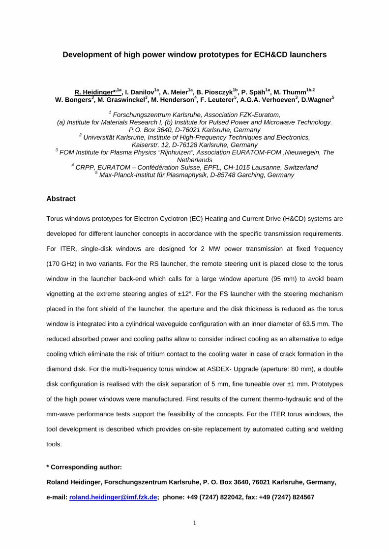
A first RS torus window prototype was manufactured to demonstrate the feasibility of the concept
(Fig. 2). The window unit was integrated into the mock-up beam line at FOM Rijnhuizen and the
transmission characteristics were analysed with a custom-made network analyser system that allows
with a dynamic range around 130 dB [7]. The potential interference of the window housing with the
beam incident from the remote steering unit was analysed by varying a gap between the window
flange and the waveguide (extension) flange, which was set to simulate the isolation valve. The
Gaussian content was extracted from the measured power profiles by fitting the measured intensity
with the help of the ideal Gaussian profile. It could be shown the power loss due to beam scrape-off is
4
below 1% consistent with a safety factor of 3 relative to the beam radius in distance to scattering
metallic parts [8]. The high power transmission characteristics were studied at the coaxial gyrotron test
stand at FZK [9]. The modest mode purity required a filtering which provide for the window testing a
RF beam of power of 170 kW with more than 97% Gaussian content and a pulse length 6.68 ms. It
was shown that the RS-window prototype did not affect the mm-wave antenna pattern (in terms of the
Gaussian beam content), did not provoke arcing even in air, satisfied vacuum specifications and did
introduce any parasitic vibrations to the RS launcher while operated with circulating cooling water [10].
Fig. 2: The RS torus window prototype shown as an explosion drawing (left) and as the manufactured window unit (right)
The design specifications and analysis of the cooling system for the RS torus window were
experimentally verified by thermo-hydraulic and pressure tests on the RS window prototype and on
window dummies in which the CVD diamond disks was substituted by a (heated) copper disk. In these
experiments, an elastic behaviour of the copper cuffs (no residual deformations) was observed up for
a pressure in the cooling loop of up to 1.6 MPa was which was twice higher then the critical water
pressure specified on the basis of the previous stress analysis. The pressure drop of the coolant
through the RS window prototype was 0.6% (6 kPa) (for a flow rate of 10 l /min and pressure of
1 MPa) which is falls much below the pressure drop in the test set-up. The temperature profile in the
disks did not differ for the horizontal and vertical arrangement of the coolant feeds, thus excluding
gravitational effects. Also it was found that the cooling efficiency entered into a flat dependence on the
water flow rate above 5 l/min was is a less demanding condition than at that obtained from the thermo-
hydraulic modelling during the design development.
5
3. Torus window for a front steering launcher
The mm-wave beam in front steering (FS) launcher propagates along the circular waveguide axis.
Thus there is no shift of the beam spot on the disk surface. This allows simplifying the window design
as compared to the RS steering case: a symmetrical arrangement of the window cuffs can be used.
As the window aperture can be reduced to 63.5 mm, the thickness of the CVD diamond disk can be
reduced to 1.11 mm (“3-half wavelengths”) as compared to 1.85 (“5-half wavelengths”). The shorter
absorptive path in the disk reduces the absorbed power from 1800 W to 1100 W for a 2 MW beam at
170 GHz and a “guaranteed” dielectric loss tangent of 4⋅10-5. Taking into account the gain in cooling
scenario which is even increased by the shorter cooling paths in the disk, the standard cooling at the
disk edge may potentially given up in favour of indirect cooling. This would eliminate the risk of tritium
contact to the cooling water in case of crack formation in the diamond disk. The two cooling concepts
were experimentally combined in the design of the FS window prototypes (cf. Fig. 3). A first unit
(“ER7_1106”: aperture 55 mm) was formed with a non-resonant disk (65 mm dia. x 1.25 mm) by which
the brazing technology was proven. The next step was the manufacturing of a close to size unit
(ER6_172: aperture 65 mm) with a resonant disk (70 mm x 1.11 mm), yet as before still with CVD
diamond of modest dielectric loss level (tanδ≈10-4). For both units, the required tolerance to
overpressure of 0.2 MPa could be proven both by simulation and experiment (cf. Tab. 1). As the
pressurising test of the cooling systems up to 3 MPa was also positive, the experimental study of the
cooling performance will be have to decide on the preferred choice among both cooling concepts and
the final design of the FS window prototype which will be based on a low loss disk (tanδ≈2-4⋅10-5) with
dimensions (75 mm dia. x 1.11 mm) suited for a window aperture of 63.5 mm.
6
Tab. 1: Experimental study and theoretical analysis of the overpressure tolerance of the FS torus
window prototype
Deformation[µm]
321210 ±10.1 MPaER7_1106
652421 ±10.2 MPa
934439 ±10.2 MPa
472219 ±10.1 MPaER6_172
σmax
[MPa]Deformation
[µm]
FEM analysisExperiment
PressureWindow unit Deformation[µm]
321210 ±10.1 MPaER7_1106
652421 ±10.2 MPa
934439 ±10.2 MPa
472219 ±10.1 MPaER6_172
σmax
[MPa]Deformation
[µm]
FEM analysisExperiment
PressureWindow unit
FlangeWindow housing
Cupper cuffs
Diamond disk Flange
FlangeWindow housing
Cupper cuffs
Diamond disk Flange
Fig. 3: The FS torus window prototype shown as an explosion drawing (left) and as the manufactured window unit (right)
4. Torus window for a step-tuneable launcher
The beam lines for advanced multifrequency ECH system at ASDEX-Upgrade (Garching, Germany)
will operate for 1 MW power levels at 4 distinct frequencies of ~105…140 GHz. Whereas the thickness
of a single-disk diamond window can be chosen such that the minimum reflection condition for the
7
radiofrequency (RF) power can be met at the boundaries of the frequency interval, for the targeted
intermediate frequencies (around 115 and 125 GHz) high power reflection will occur due to non -
resonant conditions. In double disk arrangement (nominal window thickness in our case: 1.803 and
1.820 mm, resp.), Fabry-Perot resonances, which strongly depend on the disk separation, create a
more structured spectrum (cf. Fig.4). Thus minimum reflection conditions are not only met for resonant
thickness but also for distinct intermediate frequencies which can be selected by fine tuning the
window separation. In order to cope with the typical frequency drift of high power gyrotrons (≈
100 MHz), the basic disk separation had to be kept small (i.e. 5 mm) with a setting tolerance of about
10 µm over setting range of – 1 mm to 1 mm.
Fig. 4 The power reflection characteristics of the double disk torus window for step-tuneable launcher at
ASDEX Upgrade, calculated for the basic disk separation of 5 mm (dashed) and the minimum and
maximum settings of 4 mm (solid) and 6 mm (dotted).
8
A Torus vacuum B Interspace vacuum C Atmospheric pressure side D Shafts for disk position E Guiding shafts
Fig. 5: The tuneable torus window prototype shown as a cut-away (left) and as the manufactured window unit (right)
The tight requirements for the disk separation can be satisfied by a novel direct face cooling cooling
concept (cf. fig. 5). Essentially, the double disk window is composed of the two window structures and
the housing. Each window structure consists of one diamond disk to which the two copper rings are
brazed at one face (cooling cuffs) and which are brazed in a second step into a steel flange containing
the cooling tubes and connections to the housing. The housing ensures fine tuneable adjustment of
the window separation. Spring forces provide the counteracting mechanism to allow the displacement
between vacuum and atmospheric pressure sides.
The original manufacturing was impeded by diamond failure before final brazing of the second
structure which turned out to be caused by fitting of the not fully concentric shape of the inner and
outer cuffs into the stainless steel flange. A design change in which the fitting area in the flange was
taken over by a more flexible copper insert removed this critical issue. The manufactured tuneable
torus window prototype fulfils vacuum conditions in the disk interspace (better 10-5 mbar) and water
tightness of the cooling system and is presently under preparation of cold tests.
5. Tools for in-situ replacement of ITER torus windows
Automated cutting was successfully demonstrated at a dummy of the RS torus window prototype with
a slightly oversized commercial tool TSS-NG 168 (cf. Fig. 3). Yet this allowed identifying the type TSS-
NG 141 with a working area of 73 – 141.3 mm to be suited for the RS window design and the type
TSS-NG 114 with a working area of 60 – 114 mm to be suited for the FS window design. The outer
dimensions of the tools (220 mm and 193 mm resp.) exceed the diameters of the window housings by
9
100 mm and 90 mm resp., which means that a perimeter of 50 mm has be reserved around each
window for giving access to the tool.
Fig.6 A dummy window structure for the torus window of the initial RS reference laucher with positioned automated cutting tool(left) and the blade acting on the lip welding of the flange connection to the window socket (right)
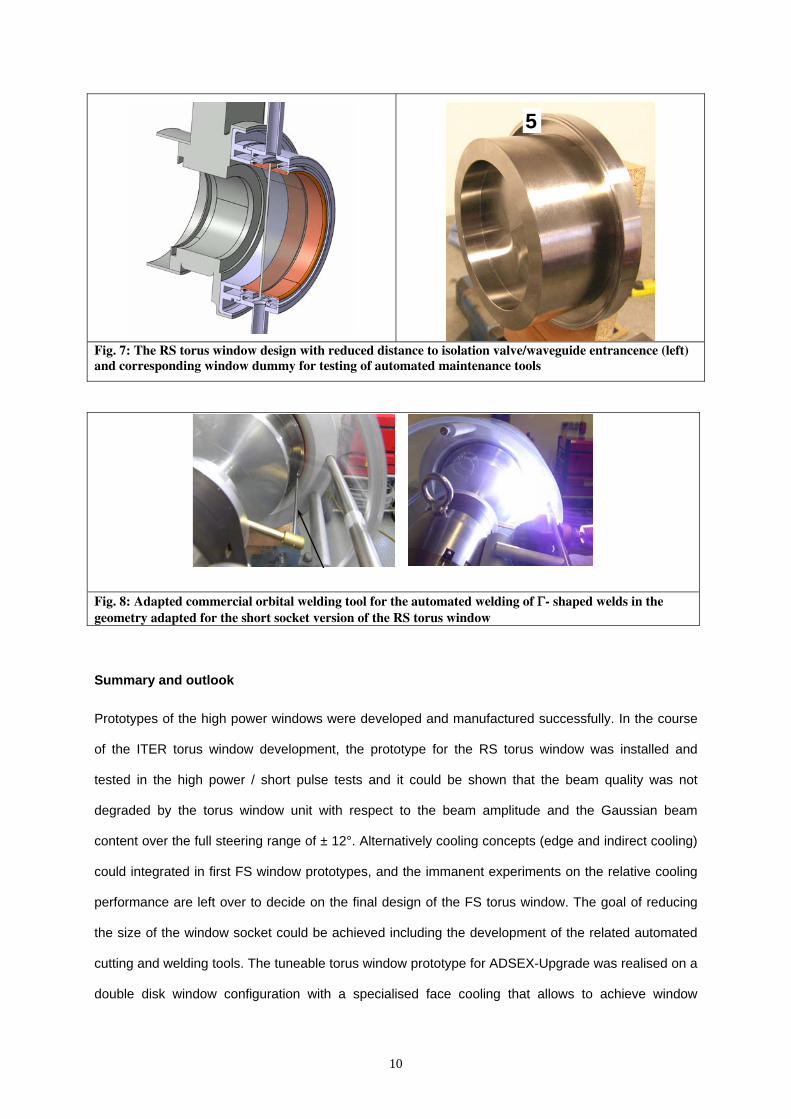
Tests of automated welding were performed with a modified commercial tube-to- sheet weld head
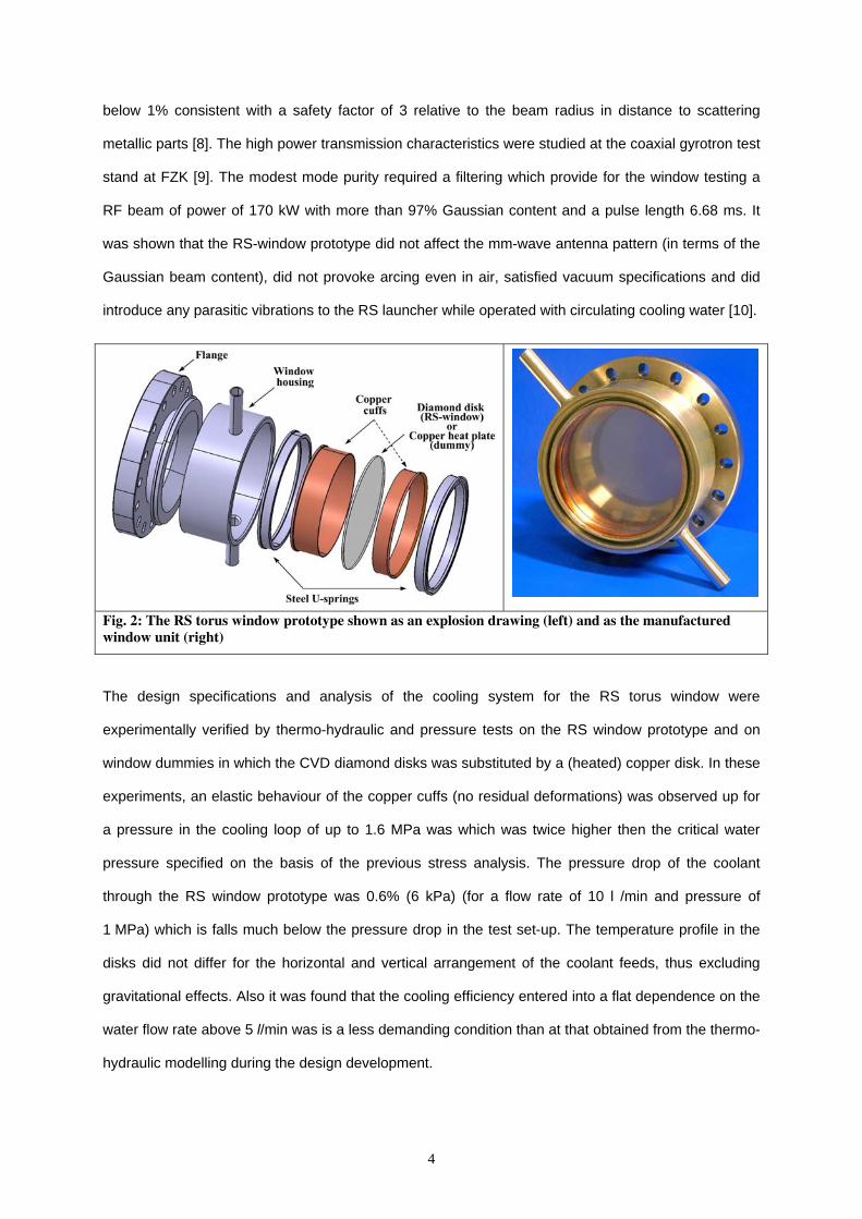
(Model 96 of Arc Machines; Much, D). Following the goal of reducing the size of the window socket for
the RS torus window in order to gain reserves for beam steering angles with respect to beam
vignetting at the window housing, the welding area was shifted close to the window housing, for which
a minimum attachment zone for the welding tool of 40 mm was to be reserved (cf. Fig. 7). Therefore a
special modification was ordered at the tool manufacturer which was compatible with the tube-to-sheet
configuration characteristic for the narrow joint of the window to the isolation flange (cf. Fig.8).
Metallographic analysis of the welds showed that the best weld characteristics showed that the
reliable welding depths down to 2.3 mm can be obtained. From the actual design of the “Γ” shaped lip,
the potential for seven window replacements at the socket could be deduced which is fulfilling any
reasonable ITER window replacement scenario.
10
5
Fig. 7: The RS torus window design with reduced distance to isolation valve/waveguide entrancence (left) and corresponding window dummy for testing of automated maintenance tools
Fig. 8: Adapted commercial orbital welding tool for the automated welding of Γ- shaped welds in the geometry adapted for the short socket version of the RS torus window
Summary and outlook
Prototypes of the high power windows were developed and manufactured successfully. In the course
of the ITER torus window development, the prototype for the RS torus window was installed and
tested in the high power / short pulse tests and it could be shown that the beam quality was not
degraded by the torus window unit with respect to the beam amplitude and the Gaussian beam
content over the full steering range of ± 12°. Alternatively cooling concepts (edge and indirect cooling)
could integrated in first FS window prototypes, and the immanent experiments on the relative cooling
performance are left over to decide on the final design of the FS torus window. The goal of reducing
the size of the window socket could be achieved including the development of the related automated
cutting and welding tools. The tuneable torus window prototype for ADSEX-Upgrade was realised on a
double disk window configuration with a specialised face cooling that allows to achieve window
11
separations of 4 … 6 mm. Cold tests are still to successfully conducted prior to its integration at the
plasma experiment.
Acknowledgment
This work, supported by the European Communities, was carried out within the framework of the
European Fusion Development Agreement. The views and opinions expressed herein do not
necessarily reflect those of the European Commission.
Literature
[1] T. Imai, N. Kobayashi, R. Temkin, M. Thumm, M.Q. Tran, V. Alikaev, ITER R&D: Auxiliary
systems: Electron Cyclotron Heating and Current Drive System, Fusion Engineering and
Design 55 (2001), pp. 281–289
[2] R. Heidinger, I. Danilov, A. Meier, M. Rohde, Material and engineering issues of CVD diamond
windows for high power mm-waves, Conf. Dig. of Joint 29th Int.Conf. on Infrared and
Millimeter Waves and 12th Int.Conf. on Terahertz Electronics, Karlsruhe, September 27 -
October 1, 2004, Piscataway, N.J. : IEEE, 2004 S.59-62
[3] R. Heidinger, M. Henderson, U. Fischer, G. Hailfinger, K. Kleefeldt, G. Saibene, A. Serikov, P.
Spaeh, A.G.A Verhoeven; Structural integration studies for the ITER ECRH Upper Launcher,
Journal of Physics: Conference Series 25 (2005), pp. 66 -74
[4] M.A. Henderson, R. Chavan , R. Heidinger, P. Nikkola, G. Ramponi, G. Saibene, F. Sanchez,
O. Sauter, A. Serikov , H. Zohm, The Front Steering Launcher Design for the ITER ECRH
Upper Port, Journal of Physics: Conference Series 25 (2005), pp. 143-150
[5] F. Leuterer, G. Grünwald, et al., Status of the new ECRH system for ASDEX Upgrade, Fusion
Engineering and Design, 74(1-4) (2005), pp. 199-203
[6] I. Danilov, R. Heidinger, A. Meier, P. Spaeh, Torus window development for the ITER ECRH
Upper Launcher, Journal of Physics: Conference Series 25 (2005), pp. 173 -180
[7] W.A. Bongers, M.F. Graswinckel, et al., Low- and high-power measurements on a remote
steering upper port launcher mockup for ITER, Dig. Joint 30th International Conference on
12
Infrared and Millimeter Waves and 13th International Conference on Terahertz Electronics,
Williamsburg, September 19-23, 2005, Piscataway, N.J.: IEEE, pp. 425-426
[8] R. Heidinger, I. Danilov, et al., Design and performance tests of a high power torus window for
a remotely steered EC launcher, Dig. Joint 30th International Conference on Infrared and
Millimeter Waves and 13th International Conference on Terahertz Electronics, Williamsburg,
September 19-23, 2005, Piscataway, N.J.: IEEE, pp. 565-566
[9] A.G.A. Verhoeven, et al., Design and test of the remote-steering ITER ECRH upper-port
launcher, Proc. of this conference
[10] I. Danilov, R. Heidinger, et al., Thermo-hydraulic performance and high hower transmission
characteristics of the RS torus window prototype, Proc. of the 14th Joint Workshop on Electron
Cyclotron Emission and Electron Cyclotron Resonance Heating, May 9 – 12, 2006, Santorini