DOCTORAL DISSERTATION Development of household appliances in an energy-autonomous house unter der Leitung von Univ.-Prof. Dipl.-Ing. Dr. techn. Ardeshir Mahdavi E 259-3 Abteilung für Bauphysik und Bauökologie Institut für Architekturwissenschaften und Dipl.-Ing. Dr. techn. Robert Wimmer Gruppe Angepasste Technologie eingereicht an der Technischen Universität Wien Fakultät für Architektur und Raumplanung von Chaipipat Pokpong Matrikelnr. 0927261 Theresianumgasse 5/2/28 1040 Wien, Österreich Wien, November 2015 Die approbierte Originalversion dieser Dissertation ist in der Hauptbibliothek der Technischen Universität Wien aufgestellt und zugänglich. http://www.ub.tuwien.ac.at The approved original version of this thesis is available at the main library of the Vienna University of Technology. http://www.ub.tuwien.ac.at/eng
Transcript
DOCTORAL DISSERTATION
Development of household appliances in an energy-autonomous
house
unter der Leitung von
Univ.-Prof. Dipl.-Ing. Dr. techn. Ardeshir Mahdavi
E 259-3 Abteilung für Bauphysik und Bauökologie
Institut für Architekturwissenschaften
und
Dipl.-Ing. Dr. techn. Robert Wimmer
Gruppe Angepasste Technologie
eingereicht an der
Technischen Universität Wien
Fakultät für Architektur und Raumplanung
von
Chaipipat Pokpong
Matrikelnr. 0927261
Theresianumgasse 5/2/28
1040 Wien, Österreich
Wien, November 2015
Die approbierte Originalversion dieser Dissertation ist in der Hauptbibliothek der Technischen Universität Wien aufgestellt und zugänglich. http://www.ub.tuwien.ac.at
The approved original version of this thesis is available at the main library of the Vienna University of Technology.
http://www.ub.tuwien.ac.at/eng
Dedicated to my parents, my family, my mother‐in‐law and friends
ZUSAMMENFASSUNG I
ZUSAMMENFASSUNG
Ein energieautonomes Haus ist ein wesentliches Konzept für ein unabhängiges
Energiesystem, das nachhaltiges Leben in der Zukunft ermöglicht. Um das Konzept des
energieautonomen Hauses zu realisieren, müssen Energiebedarfs‐
und ‐versorgungsmanagement berücksichtigt werden, sodass die Nutzerzufriedenheit
erhalten bleibt. Die vorliegende Untersuchung präsentiert ein innovatives Design, mit dem
die Nutzerakzeptanz von Haushaltsanwendungen in einem energieautonomen Haus erhöht
werden kann, in welchem ein kompaktes Erneuerbare‐Energie‐System für die
Energieversorgung eingerichtet wurde, sodass der Energiebedarf ohne Netzanbindungen
gedeckt werden kann. Es gibt eine geringe Anzahl an Haushaltsanwendungen, die
ausschließlich Erneuerbare‐Energie‐Technologien unterstützen. Design‐ und
Entwicklungsteams haben sich an Haushaltsanwendungen gewöhnt, die nur Elektrizität
nutzen, auch wenn es einige Haushaltsanwendungen gibt, die als Alternative andere
Energieformen mit besserer Energieeffizienz nutzen können.
Aus diesem Grund müssen die für Haushaltsanwendungen verwendeten Energieformen
sorgfältig optimiert werden, indem die tatsächliche Nachfrage und Verfügbarkeit von
Energie für Haushaltsanwendungen analysiert wird. Um ein besseres Verständnis dieser
Aspekte zu erhalten, enthält diese Untersuchung zwei Fallstudien, die ein innovatives Design
und die Nutzerakzeptanz evaluieren: Solarkühlschrank und Solarherd.
Diese Untersuchung präsentiert ein neues Entwicklungskonzept und Kriterien für die
Nutzerakzeptanz von Haushaltsanwendungen in einem energieautonomen Haus. Die
Ergebnisse der Studie sind in fünf miteinander verbundenen Designkomponenten
kategorisiert: 1) Auswertung der Nutzeranforderungen, 2) Energieoptimierung, 3)
Produktperformance und ‐nutzbarkeit, 4) Kompatibilität mit einem Wohngebäude und 5)
Nutzerakzeptanz.
ABSTRACT II
ABSTRACT
An energy‐autonomous house is an outstanding concept of an independent energy system
for sustainable living in the future. To realize the energy‐autonomous house concept, energy
demand and supply management need to be considered to keep user satisfaction. This re‐
search presents an innovative design to increase user acceptance of household appliances in
such an energy‐autonomous house where a compact renewable energy system has been
introduced as energy supply to serve the energy demand without grid connection. There is a
low number of household appliances which solely support renewable energy technology.
Design and development teams have been accustomed to household appliances using elec‐
tricity only, even though there are some household appliances that can alternatively use
other forms of energy with better energy efficiency.
Therefore, the types of energy input in household appliances need to be carefully optimized
by analyzing actual energy requirements and availability for operating household applianc‐
es. In order to gain a better understanding of these issues, there are two case studies in this
research that illustrate an innovative design and user acceptance evaluation as follows: solar
refrigerator and solar cooking stove.
This research presents a new development concept and user acceptance criteria for house‐
hold appliances in an energy‐autonomous house. The results of this study are categorized
into five related design components: 1) user needs interpretation, 2) energy optimization, 3)
product performance and usability, 4) compatibility with a residential building, and 5) user
acceptance.
Keywords
product development, household appliances, energy‐autonomous house, user acceptance
ACKNOLEDGEMENTS III
ACKNOWLEDGEMENTS
The author’s PhD program is supported by the staff development scholarship of King
Mongkut’s Institute of Technology Ladkrabang (KMITL) for two years and nine
months and the fellowship by Center for Appropriate Technology (GrAT) through
the whole study.
I would like to express my great gratitude to my supervisor Univ.‐Prof. Dr. Ardeshir
Mahdavi. I would like to thank him for his advice and excellent guidance to accom‐
plish my doctoral dissertation.
I also would like to give my deeply grateful acknowledgement to Dr. Robert Wim‐
mer for encouraging, supporting and supervising me in both academic works and liv‐
ing happily in Austria.
I would like to thank Dr. Myung Joo Kang for mentoring and assistance in everything
since the application process through my study and living in Vienna. I and my family
will never forget all wonderful memories and friendship from you.
In addition, I would like to thank my colleagues at the Center for Appropriate Tech‐
nology (GrAT) for kind assistance, suggestions, answering a lot of questions and
translation from German to English.
Magdalena Burghardt: Thank you for your kind assistance in translations and gram‐
mar checking, this research cannot be accomplished without you.
Sören Eikemeier: Thanks for your valuable suggestions and always helping me with
working and living in Austria.
Shima Goudarzi: Thanks for teaching me a complicated calculation lesson. Your tips
and suggestions really helped me to pass the exam.
Elisabeth, Alma, Steffi, Pia and Denise: Thanks for all your assistance in making me
work happily with GrAT.
Erwin Krug: Thank you very much for your talented handcraft to make a practical
prototype of a solar cooking stove.
Christoph Beitel: Thank you for excellent IT support.
Elizabeth Finz: Thank you for your assistance and cooperation for meeting arrange‐
ments with my supervisor.
ACKNOLEDGEMENTS IIII
Stefan Glawischnig: Thank you for your comments and suggestions for my disserta‐
tion.
And all classmates: Thank you very much for academic knowledge and sharing good
experiences.
Finally, I would like to thank for all the love, understanding and endless support from my
family. Dr. Sathaporn Pokpong, you are my role model for doing this study. This work is ded‐
icated to my mom and dad, Mrs. Uthid Pokpong and Mrs. Wandee toonsouy. Thank you,
A. Questionnaires ............................................................................................................ 88
B. Interview questions ..................................................................................................... 98
Curriculum vitae .................................................................................................................. 99
INTRODUCTION 1
1 INTRODUCTION
1.1 Overview
The Kyoto protocol to the United Nations Framework Convention on Climate change
(UNFCC) contains a long‐term commitment of EU member states to reduce energy
consumption, keep the global temperature rise below 2°C and decrease overall greenhouse
emissions by at least 20% below 1990 levels through establishing national roadmap plans to
set targets in order to stimulate refurbishment of buildings into Nearly zero‐energy buildings
in the year 2020 (EU commission 2010).
Even though the use of renewable energy sources is growing, most designers are still
accustomed to developing household products that are operated by electricity. As a result
the increasing number of users of new efficient household appliances in the EU‐27 resident
sector did not reduce electricity consumption in a residential building (Layman Report
1999). An energy efficiency report reveals that electricity consumption of residential use in
the EU‐27 still went up by 1.7% (Paolo Bertoldi et al. 2012). “Apart from the user’s behavior,
there are two complementary ways of reducing the energy consumed by products: the
labeling to raise the awareness of consumers and the energy efficiency requirements
imposed to products during the design phase. It is estimated that over 80% of all product‐
related environmental impacts are determined during the design phase of a product. On 21
October 2009, the EU adopted the Directive 2009/125/EC on eco‐design. Eco‐design aims at
reducing the environmental impact of products, including the energy consumption
throughout their entire life cycle” (EU commission 2010).
Nevertheless there are some appliances that can deliver the required energy services based
on renewable thermal energy, and thus are more energy‐efficient. In this regard, the energy
services needed by the end user (e.g. warm air, hot water, cold drinks) have to be
reconsidered in order to design the appliances that match the specific energy sources. The
innovative, yet untapped design approach requires a broad range of system thinking to
entail the gain of renewable energy and its supply to household appliances.
1.2 Motivation
The author of this thesis has been involved in the product design field and continues work‐
ing as a professional household appliance designer in Electrolux (Thailand). I was part of a
design and development team of a kitchen appliances project to bridge South East Asian
user behavior and European design. Later on, I went back into the academic field as a lec‐
turer in the industrial design department, Faculty of Architecture at King Mongkut’s Institute
INTRODUCTION 2
of Technology Ladkrabang (KMITL), where I closely worked with many architects and found
out that there are some missing links between household appliances and housing design in
term of energy utilization including layout design and infrastructure setting.
In addition, the researcher in a younger age experienced blackout situations many times in
the rural area of Thailand. Most of the household appliances can then not be used because
they are dependent on electric energy. This research could be a great chance to help resi‐
dents to live comfortably without grid connection, particularly in a remote area.
1.2.1 Importance of this study
1.2.1.1 In line with EU 2020 policy level
According to the EU 2020 policy, it is important to reduce energy consumption and increase
the use of renewable energy to promote security of energy supply, technological develop‐
ments and regional development, in particular in remote areas.
1.2.1.2 Reduce environmental impact and global warming
The European Environment Agency (EEA) believes that the rise in electricity consumption
causes a serious environmental problem because 80% of electricity generation concern fos‐
sil sources such as coal, gas, oil and nuclear sources (Wimmer and Kang 2009). Those mega‐
projects of electricity production have been questioned widely because of pollution and
environmental impact. This research can contribute to solving these problems by reducing
fossil as well as increasing renewable energy use to produce energy for the resident sector.
1.2.1.3 Increase energy shortage security
This study explores opportunities to use renewable energy in an energy‐autonomous house
to decrease the risk of electricity shortages. Varieties of renewable energy resources can
increase energy security in the house, which is better than relying on a single energy re‐
source for living in a house. In addition, a diversity of energy forms has more flexibility to
cover different forms of energy demand.
1.2.1.4 Increase the living standard of people who live in a remote area
This project can be a role model for promoting an energy self‐sufficient living concept for
people who live in a remote area. They can have a better standard of living by utilizing new
household appliance designs, such as replacing a fire wood stove with a solar cooking stove.
There are 2.5 billion people using biomass for cooking worldwide but there are 1.5 million
people who were killed by the smoke from open fire and tradition cooking stove using
(Bruce et al. 2002).
INTRODUCTION 3
1.2.1.5 The design knowledge gap
The new household appliances can be a paradigm design for the next generation of house‐
hold appliances that are compatible with renewable energy technologies. This will motivate
product designers, architects and engineers in a design and development team to fulfill ac‐
tual user needs in an energy‐autonomous house as well as to re‐consider the design process
for energy‐efficient design.
1.3 Research questions
According to the background and problems that have previously been mentioned, the re‐
search questions are as follows:
‐ What is the actual energy form that residents need for living in a house?
‐ How to design and develop household appliances that are compatible with a re‐
newable energy supply system in an energy‐autonomous house?
‐ What are the key factors for user acceptance of household appliances in an energy‐
autonomous house?
‐ How to increase user acceptance of household appliances in an energy‐ autono‐
mous house?
1.4 Aims of this study
This study aims to investigate actual needs and explore user acceptance criteria to develop a
new household appliance design concept that can be used in an energy‐autonomous house.
There are five aims of this study as follows:
1) To understand the supply demand of energy utilization in an energy‐autonomous
house
2) To reduce electricity consumption in an energy‐autonomous house by increasing
the use of renewable energy
3) To replace some electric household appliances with innovative household appliance
to increase energy efficiency
4) To investigate user acceptance criteria for a novel household appliance design so as
to increase appliance value and user satisfaction
5) To increase the standard of living of residents in an energy‐autonomous house
1.5 Expected results
A novel household appliance design concept can reduce electricity consumption in an ener‐
gy‐autonomous house and also increase renewable energy utilization, which can slow down
INTRODUCTION 4
environmental impact and global warming problems. Residents in remote areas can have a
better standard of living through efficient household appliances. The design of cutting‐edge
household appliances can be introduced and promoted as a new design trend for the next
generation of household appliances.
1.6 Structure of the thesis
The present study is briefly described in a conceptual framework (Figure 1). The study was
divided into three main tasks as follows: 1) Understanding the energy‐autonomous house
concept from literature review and identifying potential household appliances that can be
used in an energy‐autonomous house concept. 2) Implementing a design and development
principle for tangible household appliances and setting up an energy‐autonomous house
model for testing and monitoring. 3) Evaluating the developed design and comparing it with
existing traditional household appliances such as firewood cooking stoves.
This thesis consists of six chapters. After the introductory 1st, the 2nd chapter provides the
background of this study and reviews relevant literature. Chapter 3 describes the scientific
methods of the work to approach the research objectives and presents two case studies of
household appliances. The 4th chapter shows the significant results from literature reviews
and experiments. The last two chapters 5 and 6 discuss the results, conclusions and the
need for further development.
INTRODUCTION 5
Figure 1: Conceptual framework of this dissertation
BACKGROUND 6
2 CONCEPTUAL BACKGROUND
2.1 Overview
This chapter describes the definition of an energy‐autonomous house concept and funda‐
mental principles to establish a better understanding of the conditions and the actual de‐
mands and user needs in an energy‐autonomous house. Demand and supply were re‐
examined by means of literature review to identify problems and technological contradic‐
tions of existing energy systems in order to improve energy efficiency for a typical house‐
hold.
2.2 Energy‐autonomous house concept
The general definition of an energy‐autonomous house varies depending on the purpose of
particular studies. An energy‐autonomous house comprises a multi‐mechanism to supply
energy independently, without support and service from public facilities.(Vale B and Vale R
1975) “The key characteristic of an energy autonomous house is the use of green technolo‐
gy to reduce environmental impact from global warming while also providing a suitable,
high‐quality and comfortable living” (Chen et al. 2009). “The use of clean energy and house‐
hold appliances are necessary conditions for a comfortable life” (Chen 2007). Apart from
resident behavior, an energy‐autonomous house comprises three main components: 1)
passive building, 2) renewable energy supply system, and 3) household appliances.
Figure 2: Energy autonomous components
BACKGROUND 7
2.2.1 Passive building design
A passive house design uses technical and physical principles to create comfort for the resi‐
dents. There are usually six factors to control the comfort zone in a building: indoor temper‐
ature, humidity, air ventilation speed, acoustics, odor and illuminants. A passive building can
reduce space heating in a standard house by almost 90% (Feist 2005).
Passive cooling is the transfer of energy from a space or from the air to a space, in order to
achieve a lower temperature than that of the natural surroundings. Passive cooling is relat‐
ed to natural ventilation; this means it keeps the room cool without using mechanical air‐
conditioning systems. It can be a big factor of a building’s total energy consumption. A pas‐
sive building can save a huge amount of cooling energy.
2.2.2 Energy system in an energy‐autonomous house
Energy consumption basically concerns energy demand and supply in a residential building.
This study focuses on energy demand for household appliances covered by electricity and
thermal energy. On the other hand, supply refers to a compact renewable energy supply
system that can produce sufficient energy to fulfill the energy demands.
2.2.2.1 Energy demand
Worldwide economic and population growth will increase in the coming years. Therefore,
the world energy consumption will increase continuously and with a growing tendency
(Wimmer and Kang 2009). The energy demand in residential buildings can be clustered into
two major categories: 1) electricity and 2) thermal energy. These two energy types are
mainly required by household appliances in an energy‐autonomous house.
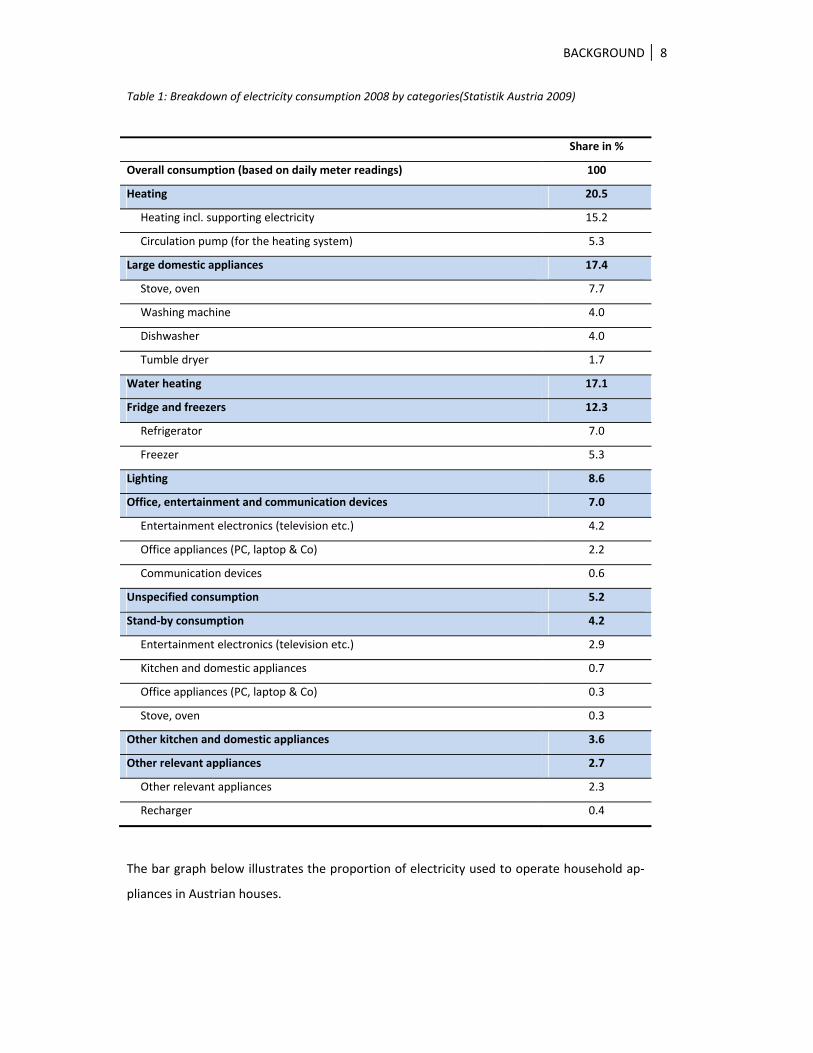
Space heating accounts for 20.5%, showing the highest consumption ratio. Large domestic
appliances such as stoves, ovens, washing machines, tumble dryers, and dishwashers ac‐
count for 17.4% of the total electricity consumption, followed by water heating with 17.1%.
Fridges and freezers are responsible for about 12% of the electricity consumption. Less than
9% are needed for lighting. The sum of all other office, entertainment and communication
devices and other kitchen and domestic appliances (e.g. vacuum cleaners) accounts for less
than 25%. “The challenge of energy‐efficient sustainable housing consists in the reduction of
heating demand by an order of magnitude in sustainable efficient way” (Steinmüller 2008).
BACKGROUND 8
Table 1: Breakdown of electricity consumption 2008 by categories(Statistik Austria 2009)
Share in %
Overall consumption (based on daily meter readings) 100
Heating 20.5
Heating incl. supporting electricity 15.2
Circulation pump (for the heating system) 5.3
Large domestic appliances 17.4
Stove, oven 7.7
Washing machine 4.0
Dishwasher 4.0
Tumble dryer 1.7
Water heating 17.1
Fridge and freezers 12.3
Refrigerator 7.0
Freezer 5.3
Lighting 8.6
Office, entertainment and communication devices 7.0
Entertainment electronics (television etc.) 4.2
Office appliances (PC, laptop & Co) 2.2
Communication devices 0.6
Unspecified consumption 5.2
Stand‐by consumption 4.2
Entertainment electronics (television etc.) 2.9
Kitchen and domestic appliances 0.7
Office appliances (PC, laptop & Co) 0.3
Stove, oven 0.3
Other kitchen and domestic appliances 3.6
Other relevant appliances 2.7
Other relevant appliances 2.3
Recharger 0.4
The bar graph below illustrates the proportion of electricity used to operate household ap‐
pliances in Austrian houses.
BACKGROUND 9
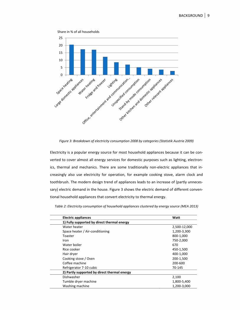
Figure 3: Breakdown of electricity consumption 2008 by categories (Statistik Austria 2009)
Electricity is a popular energy source for most household appliances because it can be con‐
verted to cover almost all energy services for domestic purposes such as lighting, electron‐
ics, thermal and mechanics. There are some traditionally non‐electric appliances that in‐
creasingly also use electricity for operation, for example cooking stove, alarm clock and
toothbrush. The modern design trend of appliances leads to an increase of (partly unneces‐
sary) electric demand in the house. Figure 3 shows the electric demand of different conven‐
tional household appliances that convert electricity to thermal energy.
Table 2: Electricity consumption of household appliances clustered by energy source (MEA 2013)
Electric appliances Watt
1) Fully supported by direct thermal energy Water heater 2,500‐12,000 Space heater / Air‐conditioning 1,200‐3,300 Toaster 800‐1,000 Iron 750‐2,000 Water boiler 670 Rice cooker 450‐1,500 Hair dryer 400‐1,000
3) Household appliances necessarily requiring electric energy
Vacuum cleaner 750‐2,000 Battery Charger 380Computer / Laptop 200‐800 Microwave 100‐1,000 Television 80‐180 Lamp / Bulb 60‐120 Radio 50‐200 CD / DVD player 25‐50
The electricity for household appliances in category 1 and 2 can be (partly) replaced by using
other energy sources without conversion in thermal household appliances based on energy
sources such as solar thermal, biomass, and biogas. In many cases it would increase energy
efficiency if the appliances used the energy source directly, with less or without energy con‐
version, to serve the user needs. The electricity in the house could be reserved for the par‐
ticular needs of lighting and for devices that necessarily require electricity. The household
appliances in category 2 can use partly electricity and partly thermal energy.
Figure 4: Electric consumption rates of thermal household appliances (MEA 2013)(Noman 2014)
Energy demands for household appliances can be categorized into two main forms which
are thermal energy and electricity.
BACKGROUND 11
2.2.2.2 Energy supply
Renewable energy on a small scale has high potential for use in an energy‐autonomous
house concept (Goudarzi 2014). The different kinds of sources of renewable energy can
reduce the risk of energy shortages by distributing alternative energy resource loads to
avoid having only electricity as main energy resource. Figure 5 shows the alternative options
to use as energy input for the energy‐autonomous house concept depending on available
resources in the house area such as solar energy, wind energy, geothermal and biomass.
Figure 5: Illustration of an energy‐autonomous house concept
2.2.2.2.1 Electricity
Electricity in an energy‐autonomous house is usually generated by photovoltaic (PV) to sup‐
ply appliances such as lighting bulbs, television, radio, etc. An inverter and controller for PV
provides a stable power output at 220V and runs 24 hours a day (Goudarzi 2014).
The storage system for electricity in the energy‐autonomous house is a back‐up system that
is used when not enough sun radiation is available, for example on a rainy day. The battery
should be kept in a dry and cold place to ensure a long lifetime and efficient working.
2.2.2.2.2 Thermal energy
Thermal energy is the most required energy for comfortable living in a house (GrAT 2014).
Most of the thermal energy in a house in a remote area usually is converted from varied
energy resources such as electricity, solar, fire wood, biogas and biomass.
BACKGROUND 12
2.2.3 Household appliances in an energy‐autonomous house
The design of household appliances designs is a key factor in achieving the energy‐
autonomous house concept. The general electric household appliances can be categorized
into two main groups. There are 25% of household appliances in a house that only need
purely electricity to operate their system, such as television, lamp and radio, etc. The re‐
maining 75% of household appliances in a house are related to thermal energy to serve user
needs, such as water heater, dish washer, washing machine, etc. Surprisingly, most modern
household appliances are operated by electricity only (Wimmer and Kang 2009). This is a
great opportunity to use direct thermal energy from a renewable energy source to reduce
electricity consumption in a house.
Figure 6: Thermal and electric demand ratio of total energy consumption (Statistik Austria 2009)
The illustration below (Figure 7) shows three groups of household appliance that concern
different types of energy input. The left side of the illustration shows some household appli‐
ances that need only electricity to operate their system. The middle column displays two
groups of household appliances which are categorized by their required temperature range
as follows: low temperature range (30°C‐90°C) and medium temperature range (90°C‐
300°C).
BACKGROUND 13
Figure 7: Household appliances’ energy sources by energy type and transport media
There are two main keys to reduce the emissions footprint of our building concept: reduce
the demand for energy in the building and reduce carbon emissions from the heating and
cooling device (UK national plan 2012). The cooling and thermal appliances in a house play
an important role in reducing the carbon footprint. The survey in this study shows two
popular household appliances that almost every Austrian household has. For those two ap‐
pliances there is also technology available that is compatible with renewable energy. There‐
fore, the selected household appliances for this study are a refrigerator and a cooking stove.
The following sections describe the basic requirements of those household appliances re‐
garding temperature, which is related to the energy supply and demand.
2.2.3.1 Refrigerator
The basic requirements of a household refrigerator and its different compartments regard‐
ing temperature are defined by an ISO standard:
“Cellar compartment: compartment intended for the storage of particular foods or beverag‐
es at a temperature warmer than that of the fresh‐food storage compartment
Chill compartment: compartment intended specifically for the storage of highly perishable
foodstuffs
Fresh‐food storage compartment: compartment intended for the storage of unfrozen food,
which may itself be divided into sub‐compartments
BACKGROUND 14
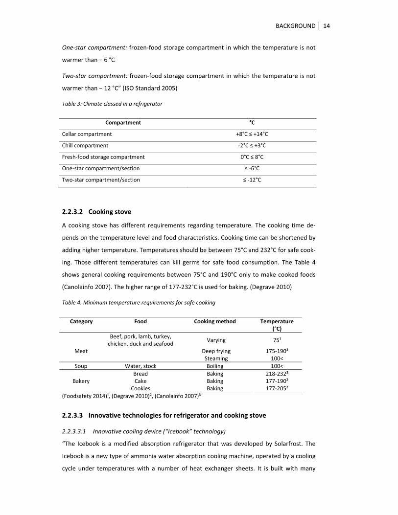
One‐star compartment: frozen‐food storage compartment in which the temperature is not
warmer than − 6 °C
Two‐star compartment: frozen‐food storage compartment in which the temperature is not
warmer than − 12 °C” (ISO Standard 2005)
Table 3: Climate classed in a refrigerator
Compartment °C
Cellar compartment +8°C ≤ +14°C
Chill compartment ‐2°C ≤ +3°C
Fresh‐food storage compartment 0°C ≤ 8°C
One‐star compartment/section ≤ ‐6°C
Two‐star compartment/section ≤ ‐12°C
2.2.3.2 Cooking stove
A cooking stove has different requirements regarding temperature. The cooking time de‐
pends on the temperature level and food characteristics. Cooking time can be shortened by
adding higher temperature. Temperatures should be between 75°C and 232°C for safe cook‐
ing. Those different temperatures can kill germs for safe food consumption. The Table 4
shows general cooking requirements between 75°C and 190°C only to make cooked foods
(Canolainfo 2007). The higher range of 177‐232°C is used for baking. (Degrave 2010)
Table 4: Minimum temperature requirements for safe cooking
Category Food Cooking method Temperature (°C)
Beef, pork, lamb, turkey, chicken, duck and seafood
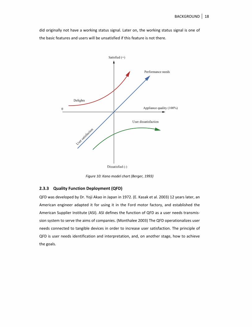
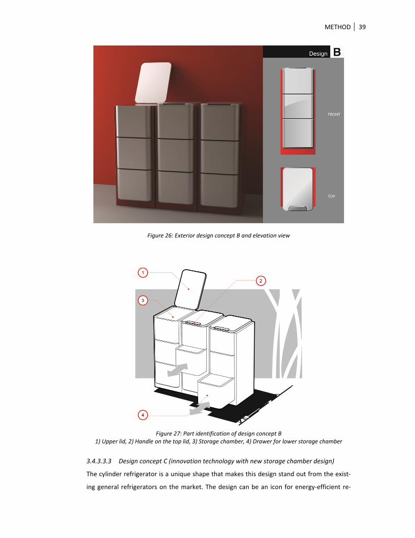
A double‐wall glass door could provide additional benefits. The user can look through the
clear glass door to see things inside the fridge before opening it. This can reduce opening
time and cooling losses. The user can plan ahead to place things or take them out while the
door is still closed. Nevertheless, huge temperature differences between inside and outside
of the fridge can make for hazy vision. Double glass with vacuum in the middle can avoid
unclear vision due to hazy glass. However, this kind of glass has high production costs. A
double‐wall curved glass with vacuum in the middle gap needs advanced technology and
specific know‐how for production.
Figure 30: The initial design concept C
METHOD 42
3.4.3.4 Refinement and design development
This follow picture shows the details of the refrigerator prototype to clarify before the pro‐
duction process. The details of the cylinder shape were clarified by creating models scale 1:5
mm with different materials such as plastic ABS and polystyrene foam. These models were
built for checking the mechanics of the rotatable tray and the door panel. The designer also
considered the locking system for stacking chamber units as well as the wall thickness. Then
a full‐scale 1:1 model was constructed from cardboard to compare the actual size with hu‐
man scale. This full‐scale model really helped the design team to make a decision on the
actual size and to improve some parts of the chamber based on direct object interaction.
Figure 31: Scale models from paper and plastic (1:5 and 1:1)
Figure 32: Section picture of refrigerator prototype
METHOD 43
Figure 33: Section picture of refrigerator chamber with rotate tray (lower view)
Figure 34: Section picture of refrigerator chamber with evaporator plate (upper view)
The design of the refrigerator uses low‐friction materials between door and track instead of
a small wheel for sliding. This can reduce production costs and time for maintenance. In
addition, a single emboss door track is easier to clean than a groove track. It is difficult to
remove dirt and water from a small groove track, which can lead to hygienic and smell prob‐
lems in a storage chamber.
The advantage of an emboss track is to block cool air from moving from inside to outside.
METHOD 44
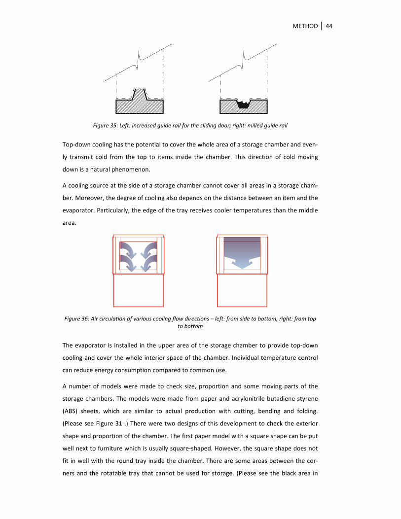
Figure 35: Left: increased guide rail for the sliding door; right: milled guide rail
Top‐down cooling has the potential to cover the whole area of a storage chamber and even‐
ly transmit cold from the top to items inside the chamber. This direction of cold moving
down is a natural phenomenon.
A cooling source at the side of a storage chamber cannot cover all areas in a storage cham‐
ber. Moreover, the degree of cooling also depends on the distance between an item and the
evaporator. Particularly, the edge of the tray receives cooler temperatures than the middle
area.
Figure 36: Air circulation of various cooling flow directions – left: from side to bottom, right: from top to bottom
The evaporator is installed in the upper area of the storage chamber to provide top‐down
cooling and cover the whole interior space of the chamber. Individual temperature control
can reduce energy consumption compared to common use.
A number of models were made to check size, proportion and some moving parts of the
storage chambers. The models were made from paper and acrylonitrile butadiene styrene
(ABS) sheets, which are similar to actual production with cutting, bending and folding.
(Please see Figure 31 .) There were two designs of this development to check the exterior
shape and proportion of the chamber. The first paper model with a square shape can be put
well next to furniture which is usually square‐shaped. However, the square shape does not
fit in well with the round tray inside the chamber. There are some areas between the cor‐
ners and the rotatable tray that cannot be used for storage. (Please see the black area in
METHOD 45
Picture (A) of Figure 37.) Even though these gaps increase interior volume inside the cham‐
ber, they also raise the working load for the cooling system without any benefit.
The cylinder shape fits the rotatable tray better than the square chamber. Nevertheless, the
cylinder shape also has some gaps at the corners between chamber exterior and ambient
furniture. (Please see the black area in Picture B of Figure 37.) However, those gaps can be
used for releasing heat from the chamber.
To sum up, both shapes have gaps at the corners. The square shape has those gaps on the
inside where the space cannot be used for any purpose, whereas the cylinder shape has
them at the outside where they can be used for air ventilation. (Figure 37)
Picture A Picture B
Figure 37: The pictures compare usage areas in the corners between rectangular (left) and round shape (right)
3.4.3.5 Cooling machine testing
Testing was set in a laboratory to control the air flow and to keep the indoor temperature
between 21°C and 27°C. The temperature of the input hot water was 80°C to drive the cool‐
ing system in the cooling machine.
The Icebook was connected to a working model of the storage chamber which was made
from two metal cylinders of different size. The chamber was cut at the side wall to put in a
slide door. 30 mm thick polystyrene (PS) foam was inserted as an insulation material into
the double wall including the door panel. The evaporator was installed at the top to provide
cold inside the cylinder.
This test setup included 4 temperature sensors to monitor the following temperatures in‐
side the chamber: 1) evaporator inlet connector, 2) evaporator outlet connector, 3) upper
storage chamber at the center of the cylinder, and 4) lower storage chamber at the center
of the storage chamber floor.
METHOD 46
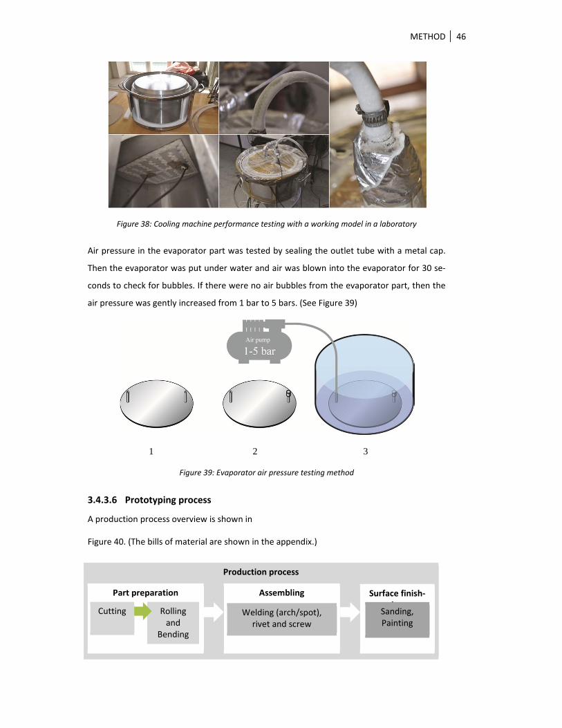
Figure 38: Cooling machine performance testing with a working model in a laboratory
Air pressure in the evaporator part was tested by sealing the outlet tube with a metal cap.
Then the evaporator was put under water and air was blown into the evaporator for 30 se‐
conds to check for bubbles. If there were no air bubbles from the evaporator part, then the
air pressure was gently increased from 1 bar to 5 bars. (See Figure 39)
1 2 3
Figure 39: Evaporator air pressure testing method
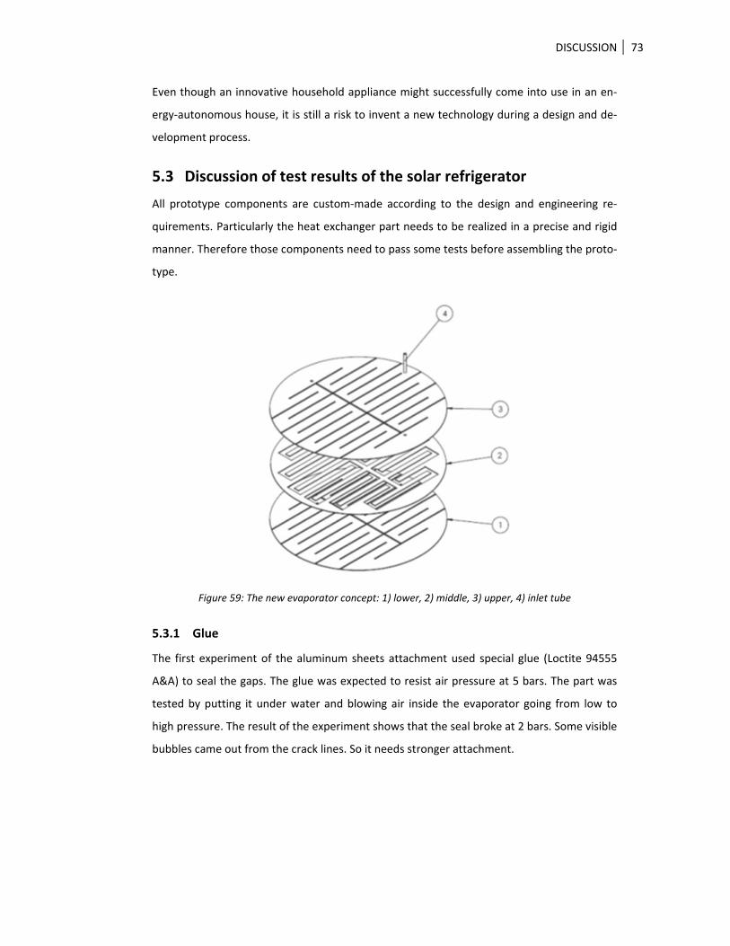
3.4.3.6 Prototyping process
A production process overview is shown in
Figure 40. (The bills of material are shown in the appendix.)
Production process
Surface finish‐ing
Assembling Part preparation
Cutting Rolling and
Bending
Welding (arch/spot), rivet and screw
Sanding, Painting
METHOD 47
Figure 40: Prototype production process overview
The storage chamber can be produced in four stages as follows: cutting, rolling/bending,
assembling and surface finishing.
3.4.3.6.1 Cutting process
The cutting process can be categorized into two methods. The first is manual cutting. This
method uses cutting tools such as hand saw, flame cutting, plasma cutting and manual mill‐
ing. These cutting methods are low‐cost but may take time and show less accuracy depend‐
ing on the skills and experience of the cutter. A second method of cutting is Computer Nu‐
merical Control (CNC). This automated cutting needs Computer Aided Design (CAD) and
Computer Aided Machine (CAM) to accomplish the cutting task. It provides a neat result and
is less time consuming. The investment costs for CNC cutting are high for a small production
volume but they may be economical for a great volume. In this project, the metal sheets
were cut with a laser cutting machine to save time and allow easy revision. For the real pro‐
duction, the metal sheets can be cut by hand sawing or any available technology that is
mentioned above. This stage represents the part preparation before the actual forming pro‐
cess.
3.4.3.6.2 Bending process
Rolling and bending are low‐cost processes for metal forming. The shape of the chamber is a
geometric form which can be easily made by these processes.
3.4.3.6.3 Assembly process
The prototype makers used arc‐welding, spot‐welding and screw techniques to assemble
the chamber. Arc‐welding was used to achieve a firm bond. This process uses very high
temperature to bond two pieces of metal. It is possible to have an unwanted bending if the
metal sheet is too thin. This process needs experience and skills to accomplish the task. It
also requires a surface treatment after work by grinding or sanding. Therefore, spot‐welding
is also used for non‐heavy load and visible areas. This kind of welding does not need a sur‐
face treatment afterwards. Some screws were used in invisible areas because they make
connection easy, with flexible adjustment afterwards.
3.4.3.6.4 Surface finishing
Surface treatment is the final stage to complete the prototype making. The arc‐welding line
needs grinding and sanding to remove unwanted parts from the work pieces. In addition,
the metal surface also needs light sanding before spray painting for better paint adhesion.
The smooth surface can reduce germ and dirt which is one of the most important criteria.
METHOD 48
3.4.4 Case study 2: solar cooking stove
3.4.4.1 Introduction
Much research was conducted that proved that a solar‐based cooking stove can provide
high temperatures sufficient for cooking foods. However, a solar‐based cooking stove has
not been widely used in households yet. This case study aims to investigate the reasons for
the low acceptance of solar cooking stoves on the part of the households, based on an anal‐
ysis of the user needs related to a traditional cooking stove and the cooking behavior. It
suggests a design guideline to design a cooking stove which is more likely to be accepted by
households. The Kano model was used to classify user needs regarding an electric cooking
stove in order to determine necessary features of a solar‐based cooking stove. The result of
this study is to improve user acceptance by using a design that bridges user needs and cook‐
ing stove features.
The main question which initiated this research was why a solar cooking stove is not widely
used in households although it meets the technical requirement of providing a certain tem‐
perature for cooking.
3.4.4.2 Technical components and optimizations of solar cooker prototype
A prototype was developed based on the solar cooker of Dr. Schwarzer’s design (Schwarzer
1993) which is a flat plate collector of indirect use type (Schwazer and Silva 2008). The new
design has different linear piping designs and insulation materials.
3.4.4.2.1 Solar collector
A solar flat plate type was used in a working prototype to measure the solar cooker perfor‐
mance. This type of solar collector is economical in both design and production. Black paint‐
ed copper tubes were assembled in a wooden box with insulation at the bottom and double
clear glass on the top. The solar collector was set with an angle about 30‐40 degree to the
ground. There are four reflector panels to reflect more sun light into the solar collector box.
Those reflector panels can also protect the glass on the solar collector when it is not in op‐
eration.
3.4.4.2.2 Thermal storage
A thermal storage tank was made from steel oil barrels with 50 liters capacity. The heat
storage was filled with round stones to reduce the thermal oil volume in the system. The
stones in the barrel can help heat to remain in a system longer with less quantity of thermal
oil. This can also keep production costs low because thermal oil is costly. The thermal stor‐
age barrel is covered with burned rice hush or glass wool for insulation.
METHOD 49
3.4.4.2.3 Cooking area
The cooking area was designed by using a double‐wall cooking vessel with a gap between
the walls for thermal oil to run through. The thin wall is more sensitive to fluctuation in
temperature than a thicker wall. However, a thick wall takes more time than a thinner wall
for gaining sufficient heat for cooking. The thermal oil can slowly move without an electric
pump by using a thermal siphon where hot oil will rise to the top part and cooler oil will go
down in a loop.
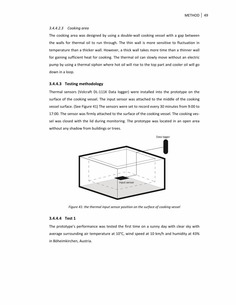
3.4.4.3 Testing methodology
Thermal sensors (Volcraft DL‐111K Data logger) were installed into the prototype on the
surface of the cooking vessel. The input sensor was attached to the middle of the cooking
vessel surface. (See Figure 41) The sensors were set to record every 30 minutes from 9:00 to
17:00. The sensor was firmly attached to the surface of the cooking vessel. The cooking ves‐
sel was closed with the lid during monitoring. The prototype was located in an open area
without any shadow from buildings or trees.
Figure 41: the thermal input sensor position on the surface of cooking vessel
3.4.4.4 Test 1
The prototype’s performance was tested the first time on a sunny day with clear sky with
average surrounding air temperature at 10°C, wind speed at 10 km/h and humidity at 43%
in Böheimkirchen, Austria.
METHOD 50
Table 9: Solar cooking stove test 1 conditions
Date 13 February 2014 (09:00‐17:00)
Air temperature 10°C
Wind speed 10 km/h
Humidity 43%
Sky condition Clear and sunny day
Place Böheimkirchen, Austria
3.4.4.5 Test 2
The second test used an improved oil flow knob for better control. Mechanical parts of the
first knob had been made from metal which enlarges at high temperatures. This problem
made it difficult to turn and caused some oil leaking. Therefore, the new test replaced the
metal control knob with a ceramic control knob which is highly heat‐resistant. In addition,
the insulation material around the hot oil storage tank was condensed to fill some gaps be‐
tween surface and air. This test was made on a sunny day with clear sky with average sur‐
rounding air temperature at 19°C, wind speed at 2 km/h and humidity at 73% in Böheimkir‐
chen, Austria.
Table 10: Solar cooking stove test 2 conditions
Date 28 August 2014 (07:00‐17:00)
Air temperature 19°C
Wind speed 2 km/h
Humidity 73%
Sky condition Clear and sunny day
Place Böheimkirchen, Austria
3.4.5 Integrated prototype
The prototype combined the cooking stove and the solar refrigerator to share the solar col‐
lector and the heat storage tank. The solar collector box was built from wood, black painted
copper tubes and clear glass. This solar collector box was topped with double glass with an
air gap in between the surface to protect the skin from burning by touching the surface. The
copper tube was painted in black color to maximize heat absorption from the sun radiation.
This solar collector uses reflector film on three foldable polystyrene foam boards on the
edges of the solar collector box. The reflector can be folded and adjusted to get maximum
sun radiation or to close the solar collector box.
METHOD 51
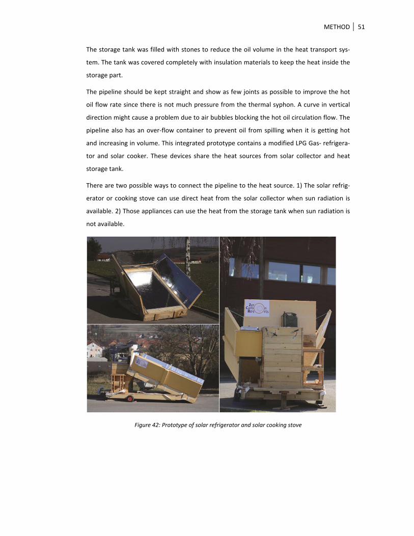
The storage tank was filled with stones to reduce the oil volume in the heat transport sys‐
tem. The tank was covered completely with insulation materials to keep the heat inside the
storage part.
The pipeline should be kept straight and show as few joints as possible to improve the hot
oil flow rate since there is not much pressure from the thermal syphon. A curve in vertical
direction might cause a problem due to air bubbles blocking the hot oil circulation flow. The
pipeline also has an over‐flow container to prevent oil from spilling when it is getting hot
and increasing in volume. This integrated prototype contains a modified LPG Gas‐ refrigera‐
tor and solar cooker. These devices share the heat sources from solar collector and heat
storage tank.
There are two possible ways to connect the pipeline to the heat source. 1) The solar refrig‐
erator or cooking stove can use direct heat from the solar collector when sun radiation is
available. 2) Those appliances can use the heat from the storage tank when sun radiation is
not available.
Figure 42: Prototype of solar refrigerator and solar cooking stove
RESULTS 52
4 RESULTS
4.1 Overview
The results of this research will be addressed in three sections. The first section focuses on
the derived results from the literature review and surveys to get a better understanding of
the demand regarding household appliances in energy‐autonomous house conditions, which
responds to the first study aim. The second section concentrates on user acceptance criteria
for household appliances in an energy‐autonomous house, which contributes to the second
study aim. The user acceptance of a novel household appliance is discussed in the third sec‐
tion to increase user satisfaction and appliance value.
4.2 Energy demand in an energy‐autonomous house
Gaining an understanding of the demand and energy‐autonomous house conditions allowed
the researcher to identify design requirements for household appliances. These require‐
ments were used to create a design and development direction for novel household appli‐
ances. User understanding does not focus only on household appliances (please see case
study 1, 2), but it includes energy needs for living in an energy‐autonomous house.
The literature review from this research reveals that thermal energy is needed by approxi‐
mately 75% of all household appliances. This is an opportunity to use thermal energy for a
household appliance directly without electric conversion which is inefficient in terms of en‐
ergy consumption. Thermal energy for household appliances can be classified into two tem‐
perature ranges: 1) low temperature range (30‐90°C) and 2) medium temperature range
(91‐300°C).
4.2.1 Low temperature range
The low temperature range refers to 30‐90°C. This range uses water as a heat transfer me‐
dia because it is a simple resource which is already available in a building. Moreover, hot
water can be shared with other household appliances with open loop circulation such as
washing machine, dish washer machine and hot water shower machine.
4.2.2 Medium temperature range
The medium temperature range refers to 91‐300°C. This range cannot use water as heat
transport media because temperatures over 100°C can be harmful to the regular infrastruc‐
ture system and residents because the water vaporizes and the pressure will damage the
sealing and piping system. So, the medium temperature range uses thermal oil such as syn‐
RESULTS 53
thetic oil or organic oil, peanut oil, avocado oil to transfer heat because it has a higher boil‐
ing point than water. However, the medium temperature range system is more expensive
than the low temperature range system because of the material and installation costs. It is
usually used for closed loop circulation.
4.3 Results of case study 1: solar refrigerator
4.3.1 Market survey and actual user needs
Survey results show the number of refrigerators owned in Austrian households. Almost eve‐
ry Austrian household (99%) has at least one refrigerator. 42.7% among these households
have more than one. The single door with freezer is the most popular type with 48.5%. The
second most popular type is a refrigerator with two doors and lower freezer with 26%.
Refrigerator buyers usually purchase a bigger capacity than they actually need. They buy a
fridge for their future uses, making sure that they have sufficient capacities for special
events. Capacity considerations involve dynamic numbers such as the number of users, spe‐
cial events and incomes. The fridge is usually purchased for long term use. 65.5% of the
fridge owners have been owning their fridge for more than four years.
The trend regarding new refrigerator design is going towards an enormous size. Competition
is very strong in the marketing of refrigerators and producers attract buyers by providing
the largest capacity. Leading brands compete to provide the largest size on the market. One
good example is that LG Electronics launched a new side‐by‐side refrigerator model with
801 liters in March 2010. Then, seven months later, Samsung Electronics launched their new
model with 840 liters in October the same year. In 2011, LG launched another model with
850 liters in March. Six months later, Samsung launched 860 liters in September and LG
launched a bigger capacity model again with 870 liters about 30 days after Samsung had
launched their last model. The competition also keeps continuously going, as 2012 Samsung
launched a refrigerator with 900 liters in July and LG topped this with 910 liters in August.
It’s obvious to see that in the last three years the capacity has been raised almost by 100
liters. This design direction might lead to electric overconsumption in a house (Statistik
Austria 2012).
RESULTS 54
Figure 43: Capacity of a new model refrigerator comparison between years 2010 – 2012 from LG Elec‐tronics and Samsung Electronics (Park 2012)
The interview and questionnaire results show that fridge buyers want to have a big capacity,
but they cannot purchase an expensive huge fridge. The number of side‐by‐side fridges has
the smallest share, only 1% of all fridges in Austria. Buyers might need a flexible‐capacity
fridge that can respond to their current requirements. For example, freshly graduated stu‐
dents might need a single compact fridge for starting their independent life. A few years
later, they can buy more units when they have a higher income. They can later have an addi‐
tional unit when they get married and have a baby.
4.3.2 User requirements and identification
The design concept was formulated from the users’ input obtained by interviewing, ques‐
tionnaires and observation. The primary information was collected in both qualitative and
quantitative data. (See Appendix A) Then the designer and engineer transformed those data
to realize a tangible device. This chapter presents three different design proposals to fulfill
user needs.
4.3.2.1 Multi‐temperature requirements
Foods require different temperature for preparing and cooking.
801
840850
860870
900910
740
760
780
800
820
840
860
880
900
920
March October March September October July August
LG Electrics SamsungCapacity (liters)
2010 2011 2012
RESULTS 55
Figure 44: Different foods require different ranges of temperature
Figure 45: Temperature cluster to reduce temperature range in a chamber
4.3.2.2 Multi‐storage chambers
The refrigerator has several compact storage chambers to separate things that require dif‐
ferent temperatures and smell controlling. The user can set the temperature individually in
each storage chamber, responding to the various food requirements.
4.3.2.3 Difficult‐to‐reach zone
Expired food is often found in the back zone of a shelf. The user has some difficulties in
reaching and searching through the back zone, because it is blocked by other items and
there’s a long reaching distance. Many users usually “push and place” their food in their
RESULTS 56
fridge: they push the food in stock into the back area and place new things in the front zone.
Then, most of the users always take food from the front zone, instead of the older food in
the back zone (if it’s the same food type). As a result, there is a lot of old food remaining in
the back zone until it goes bad.
4.3.2.4 Easy access to all areas
Design C follows an “inside‐out” and “form follows function” principle. The special feature of
this design is a rotatable tray that helps users to get comfortable access to the whole interi‐
or area by turning the tray. The users had difficulties reaching things in the back zone both
because of the distance and vision blocking. (See Figure 46‐1) The users took a longer time
opening the fridge to unblock the front zone in order to access the back zone. (See Figure
46‐2) The rotatable tray can distribute things from the back zone to the convenience zone.
(See Figure 46‐3 and Figure 46‐4.)
1 2 3 4
Figure 46: Back zone approaching
Figure 46‐1 Blocking by big things in the front zone; Figure 46‐2 Unblocking the front zone to
access the back zone; Figure 46‐3 Easy access from front zone; and Figure 46‐4 Turning the
rotatable tray from back zone to front zone so that users can easily reach things both in the
front and back zone of the fridge chamber.
4.3.2.5 Flexible capacity
The refrigerator is designed to be of flexible storage volume by adding more chambers or
decreasing the cooling volume. It is not possible to change the cooling volume in a single big
unit. The cooling volume of a fridge is a non‐static demand during different periods of time.
(The survey shows that people always buy a bigger fridge than actually needed to secure
extra capacity for the future.)
The individual cooling system offers flexible capacity by the possibility of adding an extra
unit or decreasing the cooling volume by activation or de‐activation of cooling systems. The
amount of things inside the fridge is always changing depending on the time and events. On
the one hand, users may need more space e.g. for their Christmas party. On the other hand,
RESULTS 57
they might need less space while they are travelling abroad. The refrigerator capacity can be
extended according to specific situations in life. For instance, freshly graduated students
from university might have a compact unit for their initial independent living. They can add
more units for a couple life without dumping the old fridge. An extra unit can be added
when they receive a new family member. This idea is also in line with their actual income
growths. Every unit has an individual control system to activate or de‐activate them, de‐
pending on the demand.
Figure 47: Flexible capacity according to user requirements
4.3.2.6 Flexible layout
The storage chambers can be placed horizontally or vertically, depending on purposes and
product conditions. The position of the chambers can be arranged taking into account the
frequency of usage and ergonomic considerations. They can be vertically stacked on top of
each other for multi‐user accessibility. This way, kids can access a lower unit to get their
food. If a user consumes more ice cream in summer than in winter, then the ice cream can
be placed at the most comfortable height to access the fridge in the summer. This can be
changed in winter time to store different things there, such as vegetables, meat and cheese.
In addition, those chambers can be installed horizontally on the wall at an appropriate
height so that users do not have to bend their backs to use the fridge. The horizontal instal‐
lation on the wall might be a good ergonomic position for user accessibility. For example,
cooks do not have to bend down their backs to search for ingredients in the fridge during
their cooking preparation.
4.3.2.7 Hygienic design
The design avoids sharp corners and small gaps in order to reduce dirt in the storage cham‐
ber. The interior wall is constructed with a smooth surface and waterproof to keep the
chamber clean from germs. The bottom of the chamber has a water drain hole in the center
to keep the chamber dry at all times. The water may come from melted frost at the evapo‐
rator part.
RESULTS 58
water drain hole
Figure 48: Section view shows the draining principle of refrigerator
4.3.2.8 Cleaning
The number and size of the corners in a chamber are relevant in terms of cleaning. It is more
difficult to wipe in a sharp corner than on a flat surface. Dirt always remains in the small
corners rather than in curves of a larger radius. The cubic appearance of designs A and B has
a similar number of corners in the chamber. However, the cylinder shape of design C is
smoother and has fewer corners to clean.
Figure 49: Cleaning difficulties in the interior of storage chambers
4.3.2.9 Noise
A cooling machine shouldn’t be noisy and interfere with regular activities in a house. The
buzz sound from an electric compressor can annoy users. For instance, sound from the
fridge can disturb the sleeping time of users if they live in a small house.
In general, an absorption refrigerator uses a source of heat, such as combustion of liquefied
petroleum gas, solar thermal energy or an electric heating element. These heat sources are
RESULTS 59
much quieter than the compressor motor in a typical refrigerator. In case of the ZCC, the
unwanted sound from the working system is minimized.
4.3.2.10 Improved ergonomics
Physical actions related to refrigerators and freezers are: door opening, bending the back to
access the targeted foods or beverages, loading, and cleaning. The smart design of the stor‐
age body will help users reduce hard physical movements. For example, vegetable units can
be placed at an eye level for a vegetarian user. Units for alcoholic beverage, medicine, and
cosmetics can be fixed at a higher level, to keep children away for safety reasons.
4.3.2.11 Cooling air circulation and emission
The position of the evaporator in the chamber influences air circulation and cooling perfor‐
mance. There are two possible places to install the evaporator in the chamber: in the upper
part or in the sidewall.
On the one hand, the designs A and C have the evaporator in the upper part of the chamber.
Cool air usually flows down to the bottom part while hot air goes up to the upper part. The
distance between refrigerated items and the evaporator plate is equal for all items placed
anywhere in the chamber. (Please see Figure 50 below)
On the other hand, the design B has the evaporator in the sidewall to provide cool air to the
interior space. Items that are close to the wall will get colder than items in the middle of the
chamber. Particularly, items located close to the door will get less cool temperature than
items that are located close to the wall. Moreover, the drawer wall also blocks cool temper‐
ature from getting inside the storage area.
Figure 50: The illustration compares the air circulation of designs A, B and C
4.3.2.12 Less clearance space for door opening
The sliding door of the cylinder shape does not require clearance space beside and in front
of the fridge for door opening. Because of its cylinder shape the door can hide in the side‐
wall. This design can be used in a small room or limited area.
RESULTS 60
Figure 51: Comparison of refrigerator door types
These 10 required refrigerator attributes can be categorized in 5 different groups based on
Kano’s model. (See 2.3.2)
Table 11: Needs classification of cooking stoves according to the Kano model
Needs Category
1 Multi‐temperature requirements A
2 Multi‐storage chambers A
3 ease of access M
4 Flexible capacity A
5 Flexible layout A
6 Ease of cleaning M
7 Noise O
8 Less clearance space I
9 Energy saving O
10 Durability O
4.3.3 Cooling performance results Test 1
In the first test, hot water of about 63.2°C (mean) was fed into the Icebook machine to pro‐
duce cool temperature. The temperature in the refrigerator chamber was below zero. The
temperature was quite stable. The Icebook machine can produce cool temperature of ‐3°C
to ‐1°C. The refrigerant temperature difference between input and output is approximately
3°C to 5°C. The output refrigerant temperature is lower than the input temperature. The
used hot water temperature fluctuates between 42°C and 50°C.
RESULTS 61
Figure 52: Cooling performance result from the first test
4.3.4 Cooling performance results Test 2
The Icebook machine was tested with hot water input at 71.4°C (mean) to see the different
output performance. The cool temperature line graph shows that the cool temperature is
similarly at about ‐1°C to 1°C but is less stable than in the first test. The output of the hot
water and refrigerant temperature still fluctuates, even more than in the first test. The ma‐
chine can continuously run for 6 hours to produce cool temperature.
Figure 53: Cooling performance result from the second test
RESULTS 62
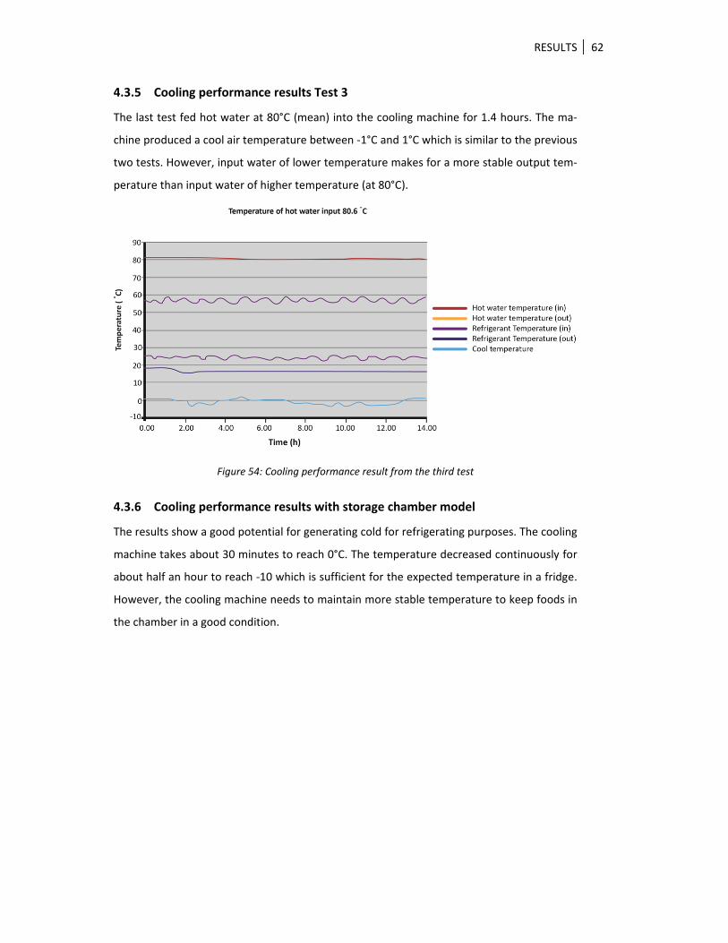
4.3.5 Cooling performance results Test 3
The last test fed hot water at 80°C (mean) into the cooling machine for 1.4 hours. The ma‐
chine produced a cool air temperature between ‐1°C and 1°C which is similar to the previous
two tests. However, input water of lower temperature makes for a more stable output tem‐
perature than input water of higher temperature (at 80°C).
Figure 54: Cooling performance result from the third test
4.3.6 Cooling performance results with storage chamber model
The results show a good potential for generating cold for refrigerating purposes. The cooling
machine takes about 30 minutes to reach 0°C. The temperature decreased continuously for
about half an hour to reach ‐10 which is sufficient for the expected temperature in a fridge.
However, the cooling machine needs to maintain more stable temperature to keep foods in
the chamber in a good condition.
RESULTS 63
Figure 55: Performance of the NH3 and water evaporator in a storage chamber model
4.3.7 Conclusion
The new solar refrigerator design C concept provides more alternative options to serve the
user demands; it reduces energy consumption by switching the energy input to solar ther‐
mal and adds some practical features that support user behavior in reducing waste of ener‐
gy during usage.
4.4 Results of case study 2: solar cooking stove
4.4.1 Market survey and actual user needs
It is crucial to gain market acceptance for the solar cooking stove because it is a new con‐
cept of household appliances that are powered by a renewable energy source without con‐
version into electrical energy. The survey consists of varied methods to gain information
about using cooking stoves, such as questionnaires, observation, interviewing and experi‐
ments.
4.4.1.1 Fast reaching of high temperature
Users prefer to shorten their cooking time. The average cooking time in 1960 was one and a
half hour. Twenty years later, cooking took an hour. Nowadays, modern cooking needs only
38 minutes. (Kirkova , 2013) Our survey showed that 76% of the participants spent only
about 20‐30 minutes for using a cooking stove. They need a high performance cooking stove
to achieve this goal. The tendency is to spend less time for cooking in a kitchen.
RESULTS 64
4.4.1.2 Precise control
A user needs to know the current temperature for cooking. An interaction between displays
and control design is very important for the user perception. The surveys reveal that 67% of
participants do not know the cooking temperature during their cooking. There are three
methods to perceive the current cooking temperature: 1) users monitor a flame characteris‐
tic of gas cooking stoves, 2) users look at the lighting signal from an electric cooking stove to
predict cooking temperature from their experience, 3) users use a knob position and
graphics to indicate a cooking temperature level. A solar cooking device needs to show the
current temperature level or preferred temperature to help control the cooking tempera‐
ture. The results of the surveys also reveal that cooks do not need to know an exact tem‐
perature for their cooking. Three temperature ranges were suggested from the participants
that are sufficient for cooking as follows: high, medium and low heat. The user also needs to
know the temperature status on the cooking surface after turning it on/off as well as a sig‐
nal of sufficient cooking temperature when it is ready to start cooking.
4.4.1.3 Easy temperature controlling
A good ergonomic design can help users to control the temperature during cooking. A good
relation between displays and control can help users to easily control the cooking tempera‐
ture. A good grip on a control knob should consider: shape, size, movement direction, posi‐
tion, color and non‐slip materials. The materials of mechanic parts inside a knob control
must resist high temperature to avoid obstructive turning or shape deformation.
4.4.1.4 Prompt use
The results of the survey showed that the participants use their cooking stove at least twice
a day. They need on average 30 minutes per cooking time. A cooking stove should have suf‐
ficient energy input and a backup system for that basic need.
4.4.1.5 Safety
Heat and physical sharp edges can harm users during cooking activities. Product designers
should avoid using ambiguous cooking zoning that causes skin burns from touching. Warn‐
ing graphics or interface designs are needed to clearly indicate a hot zone on a cooking
stove surface. A cooking stove design should avoid small corners and gaps which are difficult
for cleaning. A sharp edge can also harm users when they clean a cooking stove surface.
Users need a clear visual sign for security reasons.
RESULTS 65
4.4.1.6 Number of burners
The survey result showed that all participants would like to have more than one burner. 85%
of those have four burners on their cooking stove. It clearly indicates that users need a mul‐
ti‐burner with different sizes for their cooking. Users can cook with two burners at the same
time to save cooking time. However, users give negative feedback on a cooking stove that
has more than four burners.
4.4.1.7 Easy to clean
There are 41% of the participants who clean their cooking stove every day after cooking.
One fourth of the participants are not satisfied with their cooking stove because it is very
difficult to clean. The interview indicated that users need a dirt‐free surface during their
cooking. The users are satisfied with a flat and smooth surface on their cooking stove be‐
cause it is comfortable for removing dirt stains.
4.4.1.8 Energy saving and alternative energy used
The feedback from the surveys showed that the participants would like to use alternative
energy input for their cooking stove to reduce electricity load and to increase self‐sufficient
living by decreasing fossil energy consumption.
4.4.1.9 Aesthetics and appearance design
There is a broad range of definitions among participants for what makes an attractive physi‐
cal appearance of a cooking stove. For the most part, it can be assumed that the design
should be simple and compatible with the furniture and the surrounding environment, fur‐
thermore show practical utilities, ease of maintenance, low cost and energy saving.
4.4.1.10 Durability and maintenance
Users are satisfied with their cooking stove if it has a long working life with regular mainte‐
nance such as cleaning to keep the stove in good condition. The participants expect that
their cooking stove should work at least five years. Increase in satisfaction is directly linked
to working life time of the cooking stove.
Table 12: Needs classification of cooking stoves according to the Kano model
Needs Category
1 Temperature performance M
2 Fast reaching of high temperature O
3 Precise control M
4 Easy to control (switch on/off) I
5 Prompt use M
RESULTS 66
6 Safety – non‐toxic M
7 Number of burners I
8 Easy to clean A
9 Energy saving O
10 Aesthetic appearance I
11 Durability O
M: Must be, O: One dimension, A: Attractive, I: Indifferent, R: Reverse
4.4.2 QFD analysis
The results from Figure 56 show that the time to reach high temperature is the most im‐
portant consideration for using a cooking stove. The temperature performance is the second
priority in using a cooking stove. The solar cooking stove shows a great potential to be used
in an energy‐autonomous house in terms of energy independence, indoor‐air quality and
environmental friendliness.
Figure 56: QFD matrix of cooking stove
RESULTS 67
4.4.3 Results of test 1
In the first two hours, the temperature of the pan surface rose rapidly from 25°C to 70°C
and then slightly increased by another 10°C to the peak temperature at 80°C at 14:30. The
temperature declined between 14:30 and 15:30 and rapidly dropped to 10°C at 17:00.
Figure 57: Temperature in the cooking vessel during test 1
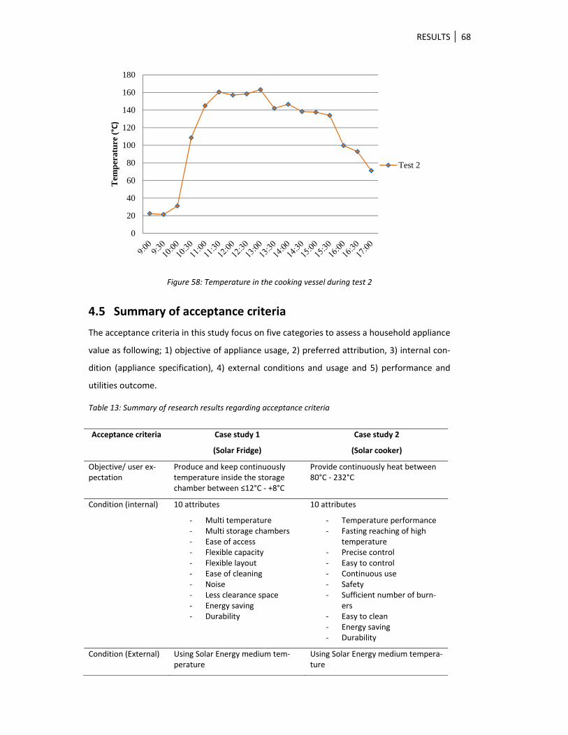
4.4.4 Results of test 2
The temperature on the pan surface slightly dropped in the first 30 minutes. The tempera‐
ture then rose up slowly for half an hour and quickly increased from 25°C to 160°C in one
and a half hours. The temperature slightly decreased between 11:30 and 12:00 and reached
the peak of 165°C at 13:00. The temperature on the surface suddenly dropped by 20°C to
145°C in 30 minutes and slightly bounded up to 150°C. After that the temperature dramati‐
cally went down until 15:30. It dropped continuously to reach 70°C at 17:00.
0
10
20
30
40
50
60
70
80
90T
emp
erat
ure
(°C
)
Test 1
RESULTS 68
Figure 58: Temperature in the cooking vessel during test 2
4.5 Summary of acceptance criteria
The acceptance criteria in this study focus on five categories to assess a household appliance
value as following; 1) objective of appliance usage, 2) preferred attribution, 3) internal con‐
dition (appliance specification), 4) external conditions and usage and 5) performance and
utilities outcome.
Table 13: Summary of research results regarding acceptance criteria
Acceptance criteria Case study 1
(Solar Fridge)
Case study 2
(Solar cooker)
Objective/ user ex‐pectation
Produce and keep continuouslytemperature inside the storage chamber between ≤12°C ‐ +8°C
Provide continuously heat between 80°C ‐ 232°C
Condition (internal) 10 attributes
‐ Multi temperature ‐ Multi storage chambers ‐ Ease of access ‐ Flexible capacity ‐ Flexible layout ‐ Ease of cleaning ‐ Noise ‐ Less clearance space ‐ Energy saving ‐ Durability
10 attributes
‐ Temperature performance ‐ Fasting reaching of high
temperature ‐ Precise control ‐ Easy to control ‐ Continuous use ‐ Safety ‐ Sufficient number of burn‐
ers ‐ Easy to clean ‐ Energy saving ‐ Durability
Condition (External) Using Solar Energy medium tem‐perature
Using Solar Energy medium tempera‐ture
0
20
40
60
80
100
120
140
160
180
Tem
per
atur
e (°C)
Test 2
RESULTS 69
Acceptance criteria Case study 1
(Solar Fridge)
Case study 2
(Solar cooker)
Usage, safety Similar to a traditional fridge,
No Freon
Slightly different from a traditional cooker
No smoke, no soot
Performance, Utili‐ties (outcome)
Partly response to user needs
Partly response to user needs
4.6 Thermal energy integration into the energy‐autonomous
house
The findings show that a compact design of a thermal energy supply system can reduce heat
losses and material costs by classifying thermal household appliances, temperature ranges
and types of circulation flows. The prototype shows the combination of a cooling and a
heating provider by using the same solar thermal technology.
A thermal energy system can be designed so as to prioritize flow to appliances in descending
order. Appliances that require high temperature should be placed closer to the thermal
source or heat storage tank than lower temperature demanding ones. The appliances can be
clustered into three different zones: 1) low temperature with open loop, 2) low temperature
with closed loop, and 3) medium temperature zone with closed loop. This is not mandatory
but it can reduce heat losses from the thermal delivery path to the ambient environment,
unless the energy delivery system has very good insulation materials to keep the heat in the
system.
DISCUSSION 70
5 DISCUSSION
The result of this study reveals that innovative appliance development and integrating to
energy‐autonomous house should focus on three components to improve a user acceptance
as following; 1) accuracy user need identification 2) delivered basic needs and 3) conditions
that make user accepted their appliance. However, these three components can be changed
under some circumstances such as behavior changing during observation, usage adaptation
according to energy capability.
5.1 Accurate user needs identification
To understand the user plays an important role in identifying user needs. Careless survey
methods can lead to distorted results. Inaccurate data input may lead into a wrong design
and development direction.
5.1.1 Data from questionnaires
The answer from the questionnaires might not be accurate, du to vague questions, location
and time of distribution. The questions should be clear and short to complete the question‐
naires. Clustering the questions in a section can make the participant better understand the
questions. In addition, there are some personal questions that the participants might be
uncomfortable to answer, such as income, age and cooking hours. These questions should
provide range answers to get the required data.
Some questions require basic technical knowledge or product specifications which the par‐
ticipants might not know or cannot recognize, for example what their appliance model’s
number is or what the capacity of their appliance is or what the main material of their appli‐
ance is. As a result, some answers were missing in the questionnaires.
It is very difficult to get information from participants in a public area unless they are wait‐
ing for something or someone. The most questionnaires were answered in a playground of a
university park where people were sitting. Almost all people who were walking on the street
usually denied answering the questionnaires.
5.1.2 Change of participant behavior during observation
Every participant usually changes their behavior during an observation, in particular in front
of the observer. This may distort some observed actions. Friendly talk before the observa‐
tion can reduce these distorted behaviors. An observer should minimize moving and noise
during the observation. The observer can ask the participants to repeat their action again to
DISCUSSION 71
get more information. The participants usually are more comfortable after they have re‐
peated their action a few times.
5.1.3 User acceptance
The level of user acceptance strongly relates to the appliance performance and external
parameters. Even though users evaluate exactly the same appliance, they might show a
difference in acceptance or perception of the appliance at a different time. Therefore, a user
needs to know the appliance specifications and performance clearly before making a deci‐
sion about an appliance. A design and development concept
Design and development of household appliances in an energy‐autonomous house can be
classified into three related layers for practical working and user satisfaction as follows: 1)
energy infrastructure in a building layer, 2) appliance design layer, and 3) user satisfaction
layer.
5.1.4 Energy infrastructure in a building layer
The layer of energy infrastructure in a building is a bridging system between energy supply
system and household appliances. It concerns building infrastructure design and engineering
work. The layer basically should be a common design for all thermal household appliances in
an energy‐autonomous house. Criteria of this standard design layer are derived from energy
system requirements such as maximum of temperature range, location of thermal output
and joints mechanism. This layer is analogous to plugging and wiring of an electricity system.
Nevertheless, an electricity system has more flexibility to place and connect household ap‐
pliances.
The energy infrastructure can be integrated into an appliance or separated from an appli‐
ance. This depends on the size and location of a device in a building.
5.1.5 Appliance design layer
The layer of appliance design refers to a design for the main structure of a device so as to
fulfill user needs. This can be designed by a conventional design process to make the device
compatible with energy infrastructure and user satisfaction criteria.
5.1.6 User satisfaction layer
The layer of user satisfaction refers to a design that foresees changeable parts and provides
options for adjustments according to various user needs. This layer is supposed to serve the
user with different designs by changing a few components.
DISCUSSION 72
5.2 Technology optimization
Technology is one of the major key factors for household appliances’ working performance
and energy saving rate in order to satisfy users. There are three potential technologies to
consider as follows.
5.2.1 Available technological components
The study reveals that using available technological components for household appliances
can satisfy users on a low‐moderate acceptance level. Most of the users can easily under‐
stand how to operate the household appliance in order to maximize working performance
and energy efficiency. However, some users feel unsatisfied with adapting their behavior to
the existing technology for energy saving or under energy‐autonomous house conditions.
Using existing technological components for a new household appliance can reduce time
consumption and investment in the design and development process.
5.2.2 Known technical principle with modifications
The feedback from the survey shows moderate up to high levels of user acceptance of
household appliances that are operated by known technological principles which are modi‐
fied. The users can mostly understand how to operate a new household appliance by refer‐
ring to experience from the original technology. A modified technology can show a better
performance than an existing technology because it was improved by adding or removing
some parts to solve a particular problem to satisfy users. Users show acceptance of a new
household appliance by slightly adjusting their behavior according to the refreshed technol‐
ogy because they might get some obvious benefit from adapting.
Known technological principles might take a little bit longer for developing, implementing
and testing them with a household appliance than using a prompt‐use, available technology.
It is also more expensive to accomplish the development than to use an existing technology.
5.2.3 New technological principle
User acceptance of using a new technological principle for household appliance depends on
several factors and conditions. Users need to learn completely new how to understand and
use a novel device effectively for their purpose and in an energy‐efficient manner. They
might take a while to learn and operate an innovative device simultaneously with adapting
their behavior. It usually consumes more time to understand how to use a new device than
the above‐mentioned technologies.
DISCUSSION 73
Even though an innovative household appliance might successfully come into use in an en‐
ergy‐autonomous house, it is still a risk to invent a new technology during a design and de‐
velopment process.
5.3 Discussion of test results of the solar refrigerator
All prototype components are custom‐made according to the design and engineering re‐
quirements. Particularly the heat exchanger part needs to be realized in a precise and rigid
manner. Therefore those components need to pass some tests before assembling the proto‐
type.
Figure 59: The new evaporator concept: 1) lower, 2) middle, 3) upper, 4) inlet tube
5.3.1 Glue
The first experiment of the aluminum sheets attachment used special glue (Loctite 94555
A&A) to seal the gaps. The glue was expected to resist air pressure at 5 bars. The part was
tested by putting it under water and blowing air inside the evaporator going from low to
high pressure. The result of the experiment shows that the seal broke at 2 bars. Some visible
bubbles came out from the crack lines. So it needs stronger attachment.
DISCUSSION 74
Figure 60: The aluminum evaporator sheet attachment with the special glue
5.3.2 Glue and rivets
For the second test we added some rivets along the edge line to close the gap between
those sheets, and we also sealed it with glue. The line of attachment was a thick line of 5
mm to have sufficient space for a cohesive glue area. Then we tested it again under water
with air pressure of 5 bars. This version can successfully resist air pressure at 5 bars but the
surface of the evaporator is not smooth and flat.
Figure 61: Evaporator seal with glue
5.3.3 Welding with aluminium
In the third version the evaporator was attached to the aluminum sheets by welding. Due to
the aluminum sheets’ thickness of only 3 mm, the shape was badly deformed from the
welding heat. Thus, attaching together those sheets should avoid direct massive heat.
The next experiment used welding methods to attach the 3 layers of aluminum sheets with
a flat surface in a firm and cohesive manner. A few versions of the cutting line were made to
DISCUSSION 75
simplify the production process. The line was narrowed down from 5 mm to 1 mm in order
to reduce working time and costs. The number of welding lines can be decreased from a
double line to a single line when the gap is smaller. The red lines in Figure 62 represent the
welding line produced to attach the aluminum sheets together. The single line welding can
save approximately 50% of time and costs compared to the double line welding.
Figure 62: The picture shows the comparison between a double welding line for the big gap and a single welding line for the small gap
The result of this process was that the work piece was badly deformed. There were two
reasons to explain this result. First, the aluminum was deformed due to very high tempera‐
ture in a large area. Second, the thickness of the aluminum sheets was too thin with only 3
mm. The researcher decided to keep the thickness at 3 mm and reduce the temperature in a
large area by using laser welding. Laser welding is very precise and strong enough for 5 bar
pressure. The outcome showed that the work piece had a slight deformation with very
strong cohesive attachment.
5.3.4 Steel sheets for the evaporator
Steel sheets are one of the possible materials for the evaporator. Even though steel doesn’t
show as good heat transfer properties as aluminum, it is stronger at the same thickness.
Steel sheets can better resist deformation caused by welding heat than aluminum. They
don’t bend due to internal air pressure (5 bars) while the ammonia changes its state be‐
tween liquid and gas. Welding thin aluminum sheets needs high skills. Steel welding is much
easier than aluminum welding because aluminum sheets get easily deformed by the high
temperature of the welding process. In addition, steel sheets are cheaper than aluminum
sheets.
5.4 Discussion of test results of the cooking stove
It is assumed that the low temperature results from hot oil leaking around the control knob
after two hours. The leak became stronger when the oil reached higher temperatures. This
leaking may cause temperature decline and some air to get inside the pipeline and block the
DISCUSSION 76
oil flow inside the system. Moreover, the control knob was very difficult to turn for control‐
ling the quantity of hot oil for the cooking area.
The temperature slightly dropped in the first 30 minutes because the oil temperature in the
oil storage tank was lower than the pan surface. Then, the temperature began to increase to
its peak after the oil absorbed heat from the solar collector. The temperature suddenly
dropped from the peak temperature (165°C) by 20°C to (145°C) because the researcher was
cooking between 13:00 and 14:00. Then the temperature slightly bounced up by about 5°C
(150°C) after the cooking finished. This phenomenon can be explained by the pan surface
losing a little bit of heat during the cooking. Then the temperature depended on the sun
radiation and weather condition. The temperature rapidly changed during cooking, which
may depend on the thickness of the pan. A thinner pan wall is more sensitive to external
parameters. A thick pan wall might hold a constant heat better than a thin pan wall. Howev‐
er, the thick pan wall might take longer time to reach high temperatures.
Figure 63: Cooking experiment with the solar cooker
5.4.1 Conceptual design
The cooking stove illustration below shows a recommended design of a cooking stove using
a simple design with round corners and smooth surfaces to reduce dirt and germ. The over‐
flow display is located in a visible position to show the level of the oil volume in the system.
DISCUSSION 77
Figure 64: Solar cooking stove design concept
5.4.2 Production simplifier
The developed absorption refrigerator represents a mid‐technology. In other words, it is
neither high‐tech, which requires large financial and resource investments, nor low‐tech,
which everyone can easily make with locally available materials. This means that the pro‐
duction of parts and the product should remain within the capacity and level of an SME. A
small‐scale local factory with trained engineers should be able to produce all components
with ordinary machinery and tools. Thus, the design of the refrigerator and solar cooking
stove take into consideration the production process and simplifies it to fall in between
mass production and craft.
5.4.3 User acceptance
Based on the analysis of the research conducted with conventional cooking stoves, this
study showed that solar cooking stoves have not been widely used in the residential sector
because of three main reasons:
The solar cooking stove can partly respond to basic attributes that users expect to have in
their cooking stove, particularly timing such as prompt using and fast temperature respond‐
ing.
DISCUSSION 78
Users only partly accept solar technology for cooking because most of the prototypes in
research still show mechanical components. A solar cooking stove still needs further ergo‐
nomics design and aesthetics to increase user satisfaction.
A solar cooking stove requires an extra infrastructure in conventional buildings. A solar
thermal energy system installation is not associated with a number of products that use
medium temperature. However, sharing the infrastructure with other household appliances
might increase investment value.
An accepted solar cooking stove design must consist of four attributes as follows: tempera‐
ture performance, precise control, prompt use and safety. There are four attributes that can
increase user acceptance for a cooking stove: fast reaching of high temperature, energy
saving ability, ease of cleaning and aesthetic appearance. In addition, an energy infrastruc‐
ture system in a building can be adapted for supply and can be shared with other household
appliances to reduce building integration‐costs.
5.5 Combining cooler and cooking stove
The prototype shows possibilities to combine the cooler and the cooking stove by using the
same energy source. This combination is a very good energy design example for other new
household appliances in the future to provide cooling and heating by sharing the same heat
source, thermal oil. This system can get benefits from switching between hot and cold in a
radical loop. An example is producing hot water from an air‐conditioner condenser. Another
good example is that the used thermal oil from the solar cooking stove can be utilized con‐
tinuously in lower temperature‐requiring appliances or to heat up water in the storage tank
for another purpose.
CONCLUSIONS 79
6 CONCLUSIONS
6.1 Research conclusions
The overall purpose of this research was to explore actual needs and implement them in
household appliances under conditions of an energy‐autonomous house. This research in‐
troduced a novel design of household appliances to accomplish an energy‐autonomous con‐
cept as well as to meet user acceptance criteria.
The study shows that thermal energy is the most demanded energy for household applianc‐
es for general living in a resident building, rather than electricity. There are a lot of energy
losses during the energy conversion from electricity to thermal energy.
Renewable energy shows the potential to provide thermal energy to fulfill user needs when
thermal household appliances switch from the use of electricity to thermal energy. This can
retain electricity for some electrical household appliances for which the energy form cannot
be replaced, such as lighting bulbs, television, computer, radio etc. The thermal energy sys‐
tem in resident buildings is recommended to have two different temperature ranges, low
temperature range and medium temperature range, to cover all household appliances re‐
quirements.
The new household appliances design concept should be able to deliver at least the design
criteria to meet user expectations. Additional functions and extra performances can also
increase user satisfaction, however, they may become expected by users over time. There‐
fore the new design concept of household appliances can be developed further to improve
performance and alternative options to fit more user needs within the energy‐autonomous
concept.
There were two case studies to represent the practical design and development of house‐
hold appliances. The first case study was a solar refrigerator. This study included experi‐
ments by implementing different technologies in a refrigerator. There are three different
technologies to explore the working potential: 1) available technological components, 2)
known technical principle with modifications, and 3) new technological principle. The results
revealed that modified technology for household appliances’ design and development has
more potential to achieve the energy‐autonomous house concept.
The second case study was an indoor solar cooking stove. This study investigated the user
acceptance value through the Kano model and Quality Function Deployment (QFD) methods
in order to review a new solar cooking stove design. The results of the study revealed that
the new solar cooking stove consists of three different design layers which have to be con‐
CONCLUSIONS 80
sidered to increase user acceptance: 1) energy infrastructure, 2) appliance design, and 3)
user satisfaction.
A solar cooking stove which can be used in an energy‐autonomous house in rural off‐grid
areas is positively accepted if the environmental impact compared to firewood cooking
stoves is considered. Changing the design and development can remarkably contribute to
solving environmental problems such as energy scarcity, shortage of electricity, or global
warming. Moreover, these new design concepts will be healthier to use and cheaper to
maintain.
Overall, the energy‐autonomous house concept can reduce electric consumption over 96%.
With this minimized consumption it becomes more feasible, practical, sustainable, environ‐
mentally friendly and affordable to supply the remaining electricity demand with solar ener‐
gy.
6.2 The study’s scientific contributions
The study provides basic criteria to increase user acceptance of household appliances that
use thermal energy as main energy input. The proposed alternative design and development
that can be a paradigm design concept for replication with other household appliances to
reduce electricity consumption in a residential building.
The research provides information on thermal energy demand and working performance of
a solar refrigerator and a solar cooking stove. This information can help architects, product
designer and engineers in planning working capacity as well as in designing a solar thermal
supply system.
This knowledge can be applied to other household appliances and also thermal energy sup‐
ply systems in an energy‐autonomous house.
6.3 Limitation of this study
This study was limited to two household appliances that use medium temperature only; the
number of case studies can be extended to other household appliances in the same or a
different temperature range, such as iron, rice cooker, and water heater for shower or
washing machine.
The present study has experimented with a specific energy‐autonomous house model to
investigate the potential of a thermal energy supply system. The thermal energy production
can be extended to various sources such as biomass, stirling engine and parabolic collectors.
Expanding the energy‐autonomous house model to full scale might provide precise infor‐
CONCLUSIONS 81
mation for other replications because the total length of the thermal piping system might
influence the thermal energy system and household devices’ capacity.
Further study in a different climate is also interesting for further experiments. This research
has been done only in Austria which is located in a temperate climate zone. The device has
more potential for practical use in a tropical country with more sunshine such as the Philip‐
pines and Thailand. This comprehensive design concept can be a very useful paradigm for
tourism industries in terms of environmental issues and customer satisfaction.
The prototypes were tested in a short period of time to get a good performance. They
should also be monitored during a longer period of time to get actual capacity and appliance
performance data throughout a whole year.
INDEX 82
INDEX
List of Figures
Figure 1: Conceptual framework of this dissertation ................................................................ 5
Figure 2: Energy autonomous components .............................................................................. 6
Figure 3: Breakdown of electricity consumption 2008 by categories (Statistik Austria 2009) . 9
Figure 4: Electric consumption rates of thermal household appliances (MEA 2013)(Noman