72
Development Of IFCs For Structural Concrete STRATEGIC PLAN INITIAL RELEASE Version 1.0 October 22, 2010
| Date post: | 01-May-2018 |
| Category: |
Documents |
| Upload: | hoangtuong |
| View: | 219 times |
| Download: | 1 times |

D e v e l o p m e n t O f I F C sF o r S t r u c t u r a l C o n c re t e
S T R AT E G I C P L A N
I N I T I A L R E L E A S EVe r s i o n 1 . 0
O c t o b e r 2 2 , 2 0 1 0
M A D E P O S S I B L E B Y T H E G E N E RO U S S U P P O RT O F :
C h a r l e s P a n ko w Fo u n d a t i o n
a n d
R M C R e s e a rc h & E d u c a t i o n Fo u n d a t i o n
i n c o n j u n c t i o n w i t h
T h e AC I Fo u n d a t i o na n d i t s S t r a t e g i c D eve l o p m e n t C o u n c i l
ATC-81 D e v e lo p m e n t o f I f C s f o R S t R u Ct u R a l C o n C R e t e
S t R at e g I C p l a n
October 22, 2010INITIAL RELEASE
Version 1.0
p R e pa R e D f o R t H e aC I f o u n Dat I o n ’ S
S t R at e g I C D e v e lo p m e n t C o u n C I l by
APPLIED TECHNOLOGY COUNCIL201 Redwood Shores Pkwy, Suite 240
Redwood City, California 94065 www.ATCouncil.org
m a n ag e m e n t
Bob Risser, Industry ChampionEdwin Dean, Principal Investigator
Thomas R. McLane, Project ManagerCharles Thornton, ATC Board Representative
Douglas Sordyl, Program Manager, ACIChris Darnell, Program Manager, SDCMichelle Kernen, Project Administrator
p R o J e Ct a Dv I S o Ry pa n e l
Dan Fragopol, PAP ChairCharles EastmanDavid Hutchinson
Jim JacobiSteve Jones Paul MlakarDeke Smith
p R o J e Ct m a n ag e m e n t C o m m I t t e e
Erleen Hatfield, Lead Engineering ConsultantAllan BommerPeter Carrato
David Grundler, Jr.Scott Hammond
Raoul KarpBill Klorman
Chi NgMike Schneider
Rob TovaniJohn Turner
Alastair WellsAaron WhitePhil Williams
table ofContentS
R e p o Rt .. . . . . . . . . . . . . . . . . . . . . . . . . . . . . . . . . . . . . . . . . . . . . . . . . . . . . . . . . . . . . . . p .. 3
p r e f a c e . p .. 3
I n t r o d u c t I o n . p .. 3
o v e rv I e w . p .. 3
d e v e l o p m e n t . G u I d e . p .. 4
S t r at e G I c . p l a n p . 4
G o a l S . p .. 5
c o n c l u S I o n . p .. 7
a p p e n D I C e S .. . . . . . . . . . . . . . . . . . . . . . . . . . . . . . . . . . . . . . . . . . . . . . . . . . . . . . . . p .. 1 0
a p p e n D I X a : Project Reference Links
a p p e n D I X b : Example Exchange Requirements Workbook, ATC-75
a p p e n D I X C : Geometry Attributes Matrix
a p p e n D I X D : Reinforcement Attributes Matrix
a p p e n D I X e : Concrete Materials Attributes Matrix
a p p e n D I X f : Project Management Attributes Matrix
a p p e n D I X g : Formwork Attributes Matrix
ATC 81 Development of IFCs for Structural Concrete Strategic Plan | INITIAL RELEASE, October 22, 20110 p. �
p R e faC e
The ACI Foundation is a subsidiary of the American Concrete Institute (ACI). It receives, administers and expends funds for educational, research and scientific purposes. The Strategic Development Council (SDC), a council of the ACI Foundation, serves to bring together the concrete industry, government and academia to focus on collaborative problem-solving in technology development. ATC-81 is one of the many ways that the SDC manifests its mission, bringing together these groups to improve the ability of software users across all professions and disciplines to effectively use Building Information Management (BIM) software tools to represent structural concrete construction.
In 2009, the ACI Foundation proposed to develop this Strategic Plan for the development of Industry Foundation Classes (IFCs) for cast-in-place (CIP), structural concrete components. The Foundation identified inconsistencies in the treatment of structural concrete components in BIM software. Because BIM software is on its way to broad adoption as the standard of care in the design and building industries, it is imperative that the concrete industry ensure that it is an effective tool for concrete design and construction. The task set forth was to specify the areas in greatest need of advancement, and to present strategies for such advancement.
Many specialized software platforms are needed to complete a project, and currently a great deal of time and money is spent duplicating design and documentation work that instead could be transferred automatically between professionals, once the software platforms can be made to effectively communicate. Many methods exist to transfer data between platforms, with varying levels of success, but IFCs have risen to become the most widely accepted method for communicating between software platforms. IFCs are neutral, non-proprietary exchange files, holding all types of building information data in a standardized format that software developers can treat uniformly. The development of better IFC representation of various aspects of structural concrete construction is the key to improving the way that professionals in the concrete construction field work with BIM technology.
The IFC protocol is extremely versatile and expandable; however, consistency in application is paramount. Consensus of users is required so that software developers can program their tools to properly interpret data from a wide variety of applications. The ACI Foundation and those who champion the goals and strategies this project recommends will bring together practitioners to determine standards of practice (such as naming conventions, measurement conventions, and the like). Dissemination of these standards will allow software providers to bridge the frustrating gaps that hinder the communication between software platforms, which would eventually allow users to hand off data seamlessly, without the costly efforts of re-working or tedious piece-by-piece examination and verification.
Because of the possibility of profound impact on the way practitioners work and use technology, the Charles Pankow Foundation emerged as a sponsor of this project. The Charles Pankow Foundation was established to provide the public with buildings of improved quality, efficiency and value by advancing innovation in building design and construction. It funds research, development and dissemination of new products and solutions that help the U.S. building construction industry be more efficient and more
RepoRt

ATC 81 Development of IFCs for Structural Concrete Strategic Plan | INITIAL RELEASE, October 22, 20110 p. �
cost competitive. Similarly, the Ready Mixed Concrete (RMC) Research and Education Foundation found a resonance with their mission and co-funded the project with the Charles Pankow Foundation. The RMC Research and Education Foundation focuses on the advancement of technology, safety and training in the concrete industry.
The Applied Technology Council (ATC) is uniquely suited to facilitate this project, following its mission of developing and promoting state-of-the-art, user-friendly engineering resources and applications. Members of the Project Advisory Panel come from backgrounds as diverse as government agencies, universities, industry publishing houses and private firms. The Project Management Committee includes engineers, architects, construction managers and software developers. Many of these participants are working together on a similar ATC project (ATC-75) and have established an efficient and robust method for moving from concept to implementation.
RepoRt
ATC 81 Development of IFCs for Structural Concrete Strategic Plan | INITIAL RELEASE, October 22, 20110 p. �
I n t R o D u Ct I o n
Currently, those who work in the design and construction field and deal with reinforced concrete designs encounter some degree of difficulty using BIM tools for this complex construction type. A great deal of work has been done advancing BIM in many areas of the building industry, structural steel construction being one example. At this juncture the concrete industry can make significant steps forward in their impact on BIM software, building on the work of other industry areas, including the progress made internationally across many types of construction.
ATC-81 is an effort to develop workable initiatives to increase the ease and efficiency of using BIM for structural concrete design and construction through enhanced interoperability or the ability to readily and reliably exchange data between disparate software programs. The Charles Pankow Foundation and the Ready Mixed Concrete Research and Education Foundation have joined forces to fund this important work through the American Concrete Institute’s ACI Foundation and its SDC. The work of the project was divided into three tasks:
ta S KS
uTask 1 - Strategic Planning Research
The Strategic Planning Research was carried out in the spring of 2010, building on the information gathered by the SDC in their 2009 survey of members’ attitudes toward and usage of BIM software and methodology and the 2007 Domain Survey compiled by the Reinforced Concrete BIM Consortium in conjunction with Tekla. The 2010 work consisted of a series of practitioner group interviews in which the interviewer sought to gather participants’ perspectives on and experience with BIM software. A diverse group of professionals participated, representing the engineering, construction, fabricating, detailing, software and academic arenas.
uTask 2 - Strategic Planning SessionThe Strategic Planning Session was held in May 2010 in conjunction with SDC Session #27. See the Strategic Planning Session Report for details on the proceedings.
uTask 3 - Strategic Plan ReportThe Strategic Plan Report is meant to capture the state of the industry and provide recommendations for initiatives that will bring meaningful and wide-ranging improvement to practitioners’ use of BIM software for reinforced concrete design,construction and facilities management.
The Strategic Plan is the culmination of efforts by participants in the ATC-81 project to identify and prioritize initiatives and determine the best candidates for carrying out the work suggested. It is the intent of this document to challenge the concrete industry and the profession to develop the means to leverage BIM technology through the use of IFCs1 to gain interoperability in the exchange of parametric modeling data. This document will be a living document, open to the addition of new initiatives, and embodying the completed and continuing work on these and possibly future initiatives set out after its first release.
1 Industry Foundation Class(es) (IFC) define the virtual representations of objects used in BIM models to
establish their attributes, their relationships and inheritances.
RepoRt
ATC 81 Development of IFCs for Structural Concrete Strategic Plan | INITIAL RELEASE, October 22, 20110 p. �
ov e Rv I e W
This strategic plan was developed to guide the cast-in-place concrete industry on the priorities for development of BIM interoperability as a means to carry the industry forward with technology that will increase quality, productivity and reduce the cost of construction. The plan presents a development guide to illustrate to the industry the basic steps to develop and prepare a National BIM exchange standard, a set of industry exchange goals and strategies accompanied by a timeline and relative cost index for development of these exchange goals. In other words, this plan lays out for the industry what needs to be done, how to approach it and when it needs to be completed in order to foster CIP concrete BIM interoperability.
The goals in this release were developed by a consensus of industry leaders during the ATC-81 Strategic Planning Session in May, 2010. Professionals from the Project Management Committee, the Project Advisory Panel and session participants were gathered to discuss the research to date and their ideas of the most productive and universally relevant steps in the endeavor to fully embrace BIM and Virtual Design & Construction. The participants divided into focus groups centered around the themes of design/detailing, detailing/manufacturing/fabrication and construction. These groups discussed what data they work with internally, and what information they “pull” from others and “push” to others. The group as a whole determined that the information that is exchanged between stakeholders should be the primary focus, so the “push” and “pull” data became the first tier of priorities. The focus groups developed lists of goals for improving the data exchanges discussed and identified the proper parties to pursue each goal. The section of this document discussing the goals and strategies is meant to be a guideline. Each goal is listed with a title, an identified champion, a guideline definition or scope, and estimates of the time and cost investment involved. The planning group has suggested the goal, but the champion was selected as the expert agency judged to be the best group to carry the initiative forward and should be free to evolve the goal as appropriate.
The goals are achieved through development of an exchange standard. The development of an exchange standard is a process defined in the National BIM Standard™ (NBIMS). The plan provides an overview of the NBIMS process. The working groups that will be preparing the exchange standard would work within the criteria of the latest NBIMS processes to develop the exchange standard.
The NBIMS process defines the means by which the goals laid out for achieving a critical level of BIM interoperability can be achieved. This plan represents an ongoing process that industry needs to embrace and continue to carry forward. Through its successful implementation a greater and growing level of interoperability will be achieved, resulting in increased efficiency, quality and sustainability across all participants in the concrete construction industry.
RepoRt
ATC 81 Development of IFCs for Structural Concrete Strategic Plan | INITIAL RELEASE, October 22, 20110 p. �
D e v e lo p m e n t g u I D e
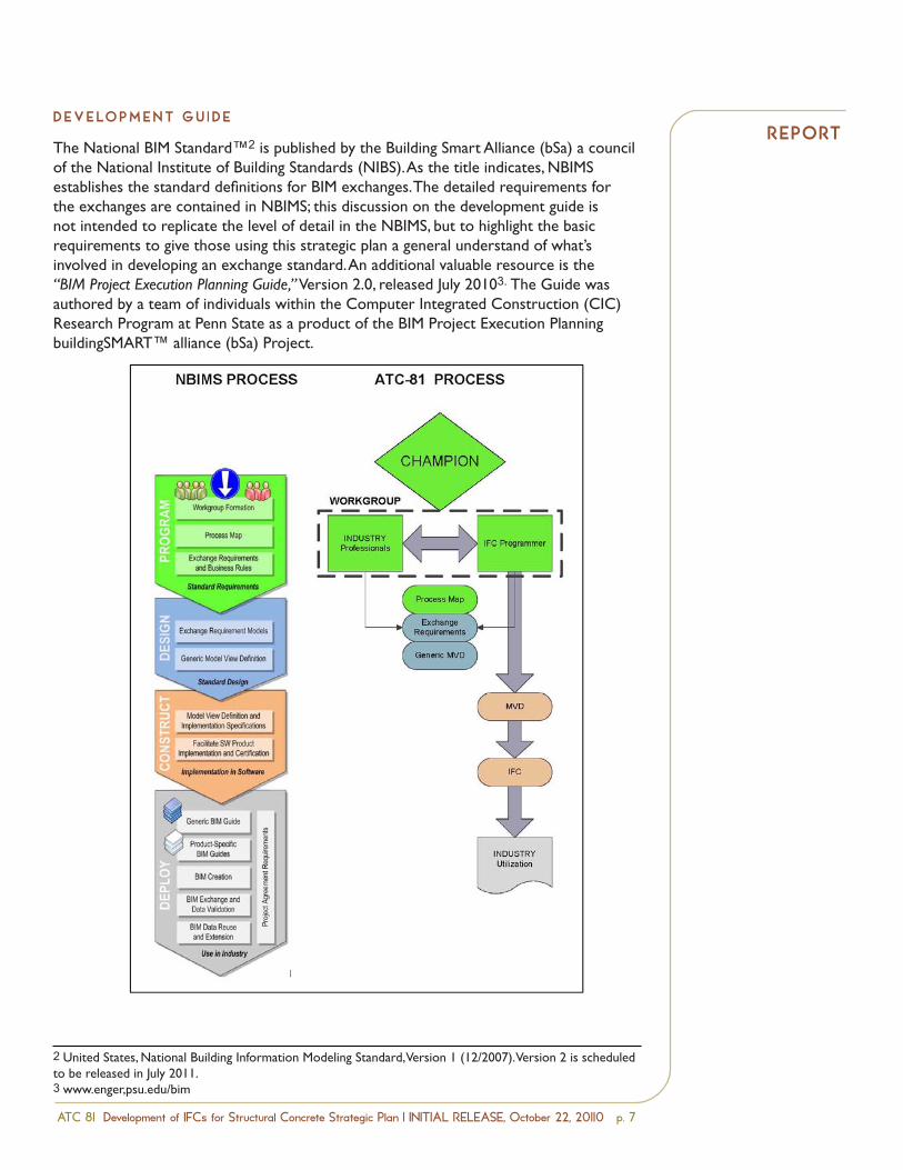
The National BIM Standard™2 is published by the Building Smart Alliance (bSa) a council of the National Institute of Building Standards (NIBS). As the title indicates, NBIMS establishes the standard definitions for BIM exchanges. The detailed requirements for the exchanges are contained in NBIMS; this discussion on the development guide is not intended to replicate the level of detail in the NBIMS, but to highlight the basic requirements to give those using this strategic plan a general understand of what’s involved in developing an exchange standard. An additional valuable resource is the “BIM Project Execution Planning Guide,” Version 2.0, released July 20103. The Guide was authored by a team of individuals within the Computer Integrated Construction (CIC) Research Program at Penn State as a product of the BIM Project Execution Planning buildingSMART™ alliance (bSa) Project.
RepoRt
2 United States, National Building Information Modeling Standard, Version 1 (12/2007). Version 2 is scheduled to be released in July 2011.3 www.enger,psu.edu/bim
ATC 81 Development of IFCs for Structural Concrete D R A F TStrategic Plan September 15, 2010
Page 9
involved in developing an exchange standard. An additional resource is the soon to be released, “Howto Develop and Prepare a National BIM Exchange Standard: A How To Do It Guide”, by Chuck Eastman,Ivan Panushev, Rafael Sacks, and Elif Yagmur. This guide is based on the authors’ experiences andlessons learned in developing an exchange standard for precast concrete.
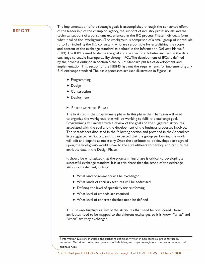
The implementation of the strategic goals is accomplished through the concerted effort of theleadership of the champion agency, the support of industry professionals and the technical support of aconsultant experienced in the IFC process. These individuals form what it called the “workgroup”. Theworkgroup is comprised of a small group of individuals (5 to 15), including the IFC consultant, who areresponsible for establishing the scope and context of the exchange standard as defined in the
Information Delivery Manual3
(IDM). The IDM is used todefine the goal and the specificattributes involved in the dataexchange to enableinteroperability through IFCs.The development of IFCs isdefined by the processoutlined in Section 5 the NBIMStandard phases ofdevelopment andimplementation. This sectionof the NBIMS lays out therequirements forimplementing any BIMexchange standard. The basicprocesses are (see illustrationin Figure 1):
ProgrammingDesignConstructionDeployment
3 Information Delivery Manual is the exchange definition written in non technical prose for use by end users.Describes the business process, stakeholders, exchange points, information requirements and business rules.
Figure 1: NBIMS Process for Developing Exchange Standards
ATC 81 Development of IFCs for Structural Concrete Strategic Plan | INITIAL RELEASE, October 22, 20110 p. 8
The implementation of the strategic goals is accomplished through the concerted effort of the leadership of the champion agency, the support of industry professionals and the technical support of a consultant experienced in the IFC process. These individuals form what it called the “workgroup”. The workgroup is comprised of a small group of individuals (5 to 15), including the IFC consultant, who are responsible for establishing the scope and context of the exchange standard as defined in the Information Delivery Manual3 (IDM). The IDM is used to define the goal and the specific attributes involved in the data exchange to enable interoperability through IFCs. The development of IFCs is defined by the process outlined in Section 5 the NBIM Standard phases of development and implementation. This section of the NBIMS lays out the requirements for implementing any BIM exchange standard. The basic processes are (see illustration in Figure 1):
Programming
Design
Construction
Deployment
u p r o G r a m m I n G . p h a S e
The first step is the programming phase. In this phase the Champion will need to organize the workgroup that will be working to fulfill the exchange goal. Programming will initiate with a review of the goal and the suggested attributes associated with the goal and the development of the business processes involved. The spreadsheet discussed in the following section and provided in the Appendices lists suggested attributes, and it is expected that the group performing the work will edit and expand as necessary. Once the attributes to be developed are agreed upon, the workgroup would move to the spreadsheets to develop and capture the attribute data in the Design Phase.
It should be emphasized that the programming phase is critical to developing a successful exchange standard. It is at this phase that the scope of the exchange attributes is defined, such as:
What kind of geometry will be exchanged
What kinds of ancillary features will be addressed
Defining the level of specificity for reinforcing
What level of embeds are required
What level of concrete finishes need be defined
This list only highlights a few of the attributes that need be considered. These attributes need to be mapped to the different exchanges, so it is known “what” and “when” are they exchanged.
Ñ
Ñ
Ñ
Ñ
Ñ
Ñ
Ñ
Ñ
Ñ
RepoRt
3 Information Delivery Manual is the exchange definition written in non-technical prose for use by end-users. Describes the business process, stakeholders, exchange points, information requirements and
business rules.
ATC 81 Development of IFCs for Structural Concrete Strategic Plan | INITIAL RELEASE, October 22, 20110 p. �
u d e S I G n . p h a S e
“Design” refers to organizing the exchange information in a format that takes into account the existing concepts as well as those new to a particular exchange requirement. The format is presented in a manner that allows it to bridge the exchange dialogue between the language of the industry members of the working group and that of the software programmers. The developed exchange requirements are then utilized in the development of the products of the Construction Phase. The resources developed in this phase should be coordinated with and delivered to the IFC Solutions Factory permitting a broad international coordination and dissemination with other interested parties.
u c o n S t r u c t I o n . p h a S e
The “Construction” phase is a reference to constructing or linking the generic information exchange requirements of the design phase, with the specific elements that exist or need to be developed in the standard IFC schema or the specific programming language structure. The ‘constructed’ schema is formatted into Model View Definitions (MVDs)4 that permit the object data exchanges to occur through IFC files. The construction phase will also address help with test models for implementation: both drawing models to implement, then export, and P-21 or XML files to import.
u d e p l oy m e n t . p h a S e
Deployment begins once the technical work of generating the MVDs and binding them to the IFCs is completed. They are then are ready to be implemented into a variety of software applications to support the interchange of BIM object data. The overarching goal of interoperability is finally achieved through implementation and validation of the exchange protocols. Deployment will also need to consider the technical validation and testing of the functioning IFC exchanges to ascertain that they are working as the program users intended.
D e ta I l e D D e v e lo p m e n t C o n S I D e R at I o n S
The overarching purpose of these efforts is to develop software-friendly data structures, which will allow BIM software programmers and BIM users (practitioners) to better accommodate reinforced concrete construction data and practices. The ATC-75 project developed IFCs for the structural domain using the NBIMS exchange protocols and can serve as a ready reference to how this process can apply here to the CIP concrete effort. The ATC-75 project was a broad effort to begin to shape data exchanges for the collective assets that are a part of the structural domain, including concrete construction, and is therefore a useful reference for this effort.
How does the process begin and what activities need to occur to achieve the development of an exchange standard? The process begins with the establishment of the workgroup, its Chair and the formulation of the IDM. Within the IDM the workgroup will need to define the user requirements and business processes involved and the exchange requirements involved. These two fundamental tasks are discussed in the following section.
RepoRt
4 Model View Definition is the technical exchange definition for use by software developers.
ATC 81 Development of IFCs for Structural Concrete Strategic Plan | INITIAL RELEASE, October 22, 20110 p. 10
u p r o G r a m . p h a S e :. B u S I n e S S . p r o c e S S . m a p S.
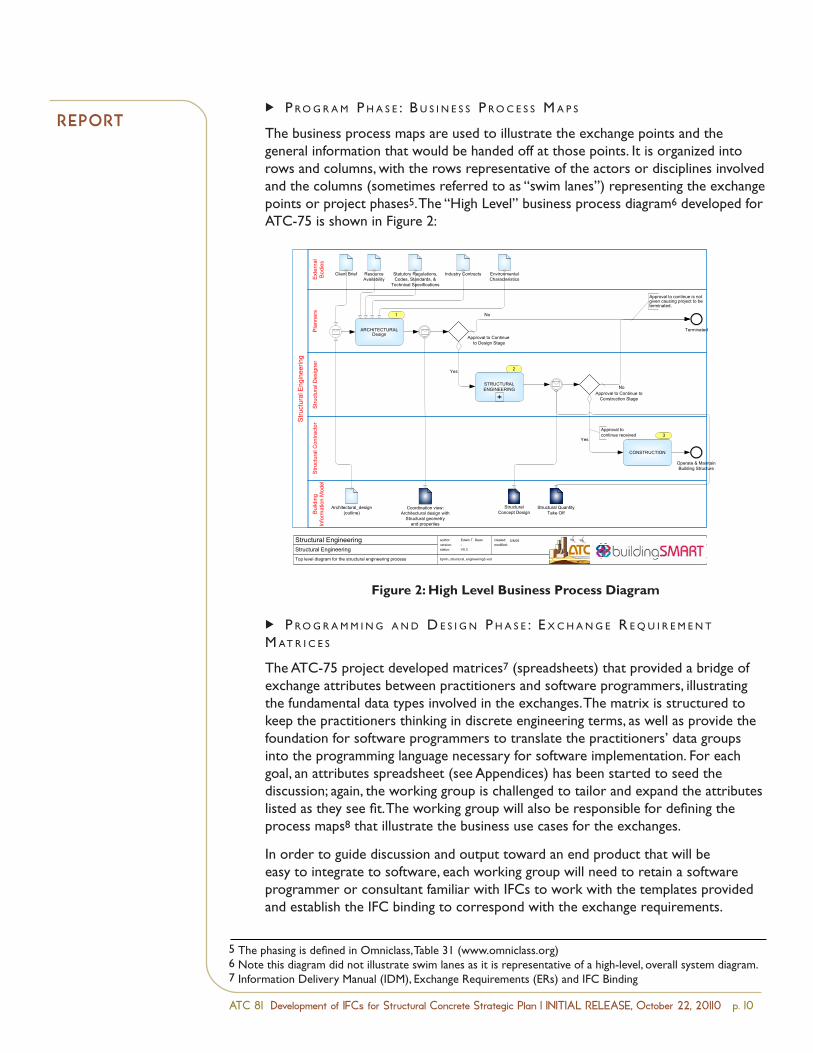
The business process maps are used to illustrate the exchange points and the general information that would be handed off at those points. It is organized into rows and columns, with the rows representative of the actors or disciplines involved and the columns (sometimes referred to as “swim lanes”) representing the exchange points or project phases5. The “High Level” business process diagram6 developed for ATC-75 is shown in Figure 2:
Figure 2: High Level Business Process Diagram
u p r o G r a m m I n G . a n d . d e S I G n . p h a S e :. e x c h a n G e . r e q u I r e m e n t.m at r I c e S.
The ATC-75 project developed matrices7 (spreadsheets) that provided a bridge of exchange attributes between practitioners and software programmers, illustrating the fundamental data types involved in the exchanges. The matrix is structured to keep the practitioners thinking in discrete engineering terms, as well as provide the foundation for software programmers to translate the practitioners’ data groups into the programming language necessary for software implementation. For each goal, an attributes spreadsheet (see Appendices) has been started to seed the discussion; again, the working group is challenged to tailor and expand the attributes listed as they see fit. The working group will also be responsible for defining the process maps8 that illustrate the business use cases for the exchanges.
In order to guide discussion and output toward an end product that will be easy to integrate to software, each working group will need to retain a software programmer or consultant familiar with IFCs to work with the templates provided and establish the IFC binding to correspond with the exchange requirements.
RepoRt
ATC 81 Development of IFCs for Structural Concrete D R A F TStrategic Plan September 15, 2010
Page 11
protocols. Deployment will also need to consider the technical validation and testing of thefunctioning IFC exchanges to ascertain that they are working as the program users intendedthem to apply.
Detailed Development ConsiderationsThe overarching purpose of these efforts is to develop software friendly data structures, which willallow BIM software programmers and BIM users (practitioners) to better accommodate reinforcedconcrete construction data and practices. The ATC 75 project developed IFCs for the structural domainusing the NBIMS exchange protocols and can serve as a ready reference to how this process can applyhere to the CIP concrete effort. The ATC 75 project was a broad effort to begin to shape data exchangesfor the collective assets that are a part of the structural domain, including concrete construction, and istherefore a useful reference for this effort.
How does the process begin and what activities need to occur to achieve the development of anexchange standard? The process begins with the establishment of the workgroup, its Chair and theformulation of the IDM. Within the IDM the workgroup will need to define the user requirements andbusiness processes involved and the exchange requirements involved. These two fundamental tasks arediscussed in the following section.
Program Phase – Business Process MapsThe business process maps are used to illustrate the exchange points and the generalinformation that would be handed off at those points. It is organized into rows and columns,with the rows representative of the actors or disciplines involved and the columns (sometimesreferred to as “swim lanes”) representing the exchange points or project phases5. The “HighLevel” business process diagram6 developed for ATC 75 is shown in Figure 2:
Pla
nner
s
Stru
ctur
al E
ngin
eerin
g
Stru
ctur
al D
esig
ner
1
2
3
Stru
ctur
al C
ontra
ctor
Structural EngineeringStructural EngineeringTop level diagram for the structural engineering process
author:version:status:
Edwin T. Dean-V0.3
created:modified:
bpmn_structural_engineering3.vsd
Bui
ldin
g In
form
atio
n M
odel
Ext
erna
l B
odie
s
Architectural_design(outline)
Structural Quantity Take Off
Resource Availability
Statutory Regulations, Codes, Standards, &
Technical Specifications
Industry Contracts Environmental Characteristics
Approval to Continueto Design Stage
Yes
Terminated
No
Approval to Continue to Construction Stage
Yes
Approval to continue received
No
Operate & Maintain Building Structure
Client Brief
Coordination view:Architectural design with
Structural geometry and properties
Approval to continue is not given causing project to be terminated.
STRUCTURALENGINEERING
ARCHITECTURALDesign
CONSTRUCTION
5/8/09
StructuralConcept Design
Figure 2: High Level Business Process Diagram
5 The phasing is defined in Omniclass, Table 31 (www.omniclass.org)6 Note this diagram did not illustrate swim lanes as it is representative of a high level, overall system diagram.
5 The phasing is defined in Omniclass, Table 31 (www.omniclass.org)6 Note this diagram did not illustrate swim lanes as it is representative of a high-level, overall system diagram.7 Information Delivery Manual (IDM), Exchange Requirements (ERs) and IFC Binding
ATC 81 Development of IFCs for Structural Concrete Strategic Plan | INITIAL RELEASE, October 22, 20110 p. 11
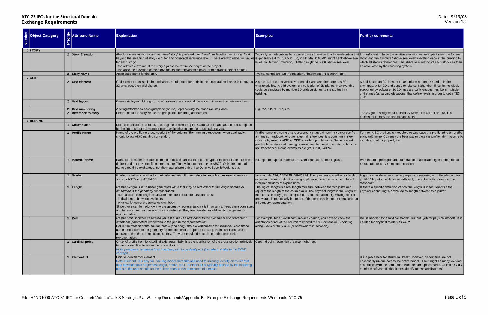
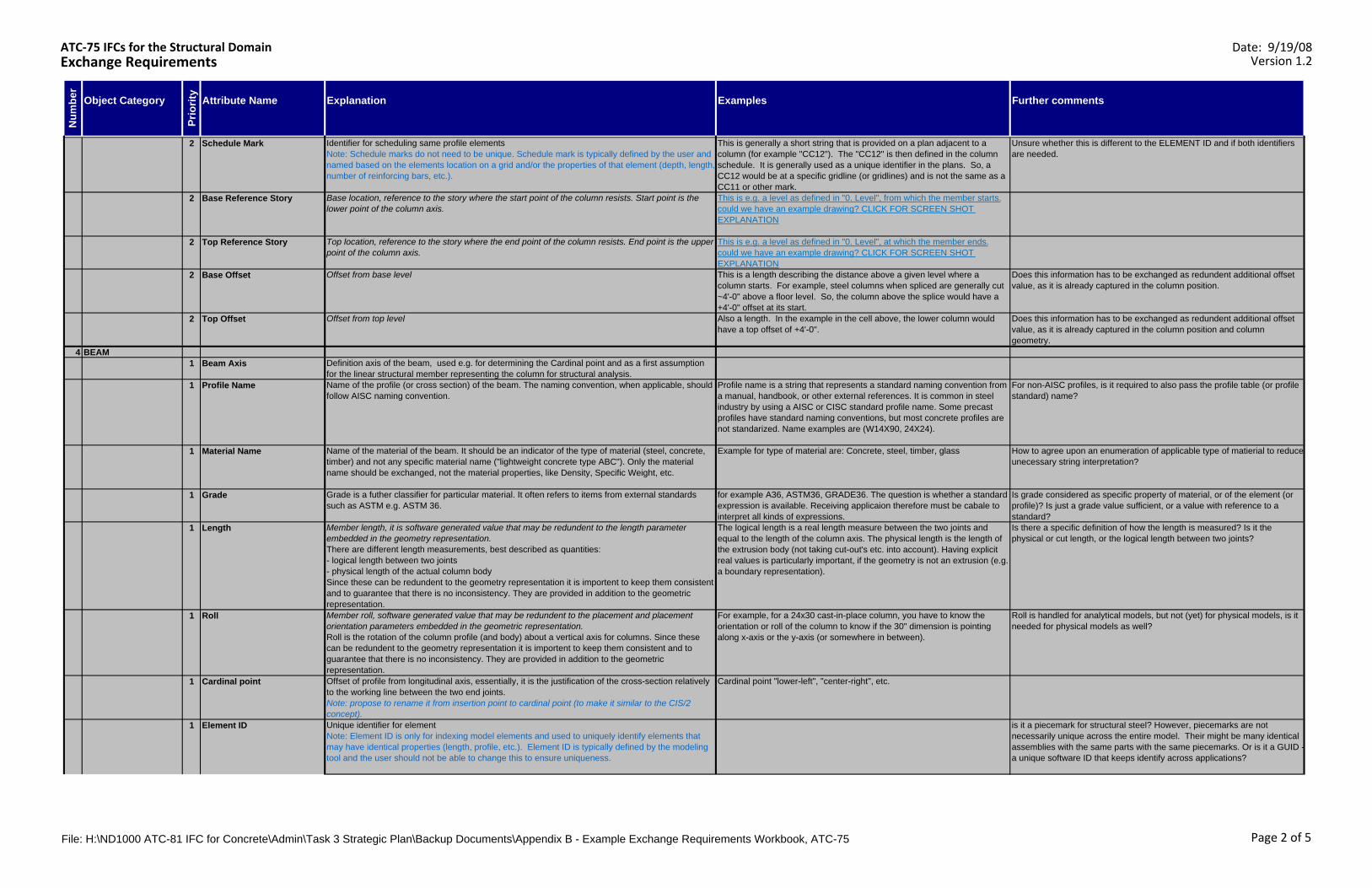
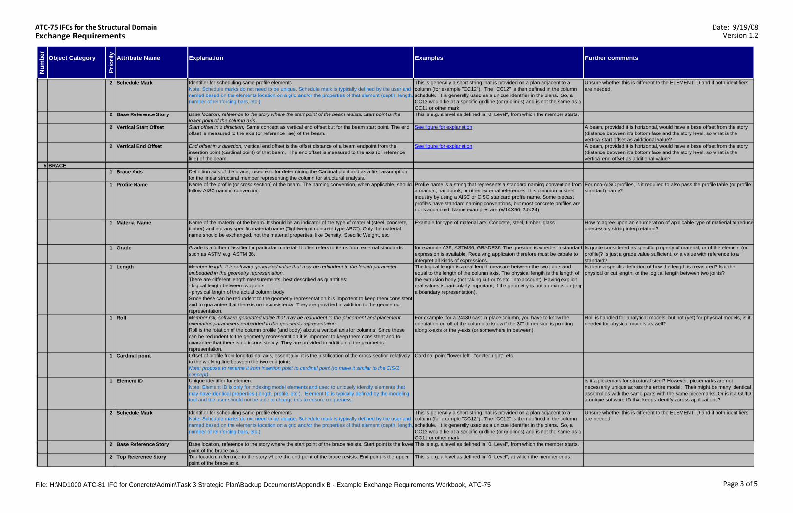
RepoRtThe ATC-75 project developed a system of very general process maps illustrating the exchange points and a system of matrices or spreadsheets9 used to format the exchange requirements. There are two spreadsheets provided for the working group’s use. The first, “Exchange Requirements”, is a document that acts as a conversation between the practitioners and the software programmer, guiding the development of the attribute data in ways that are clear and useful for software implementation.
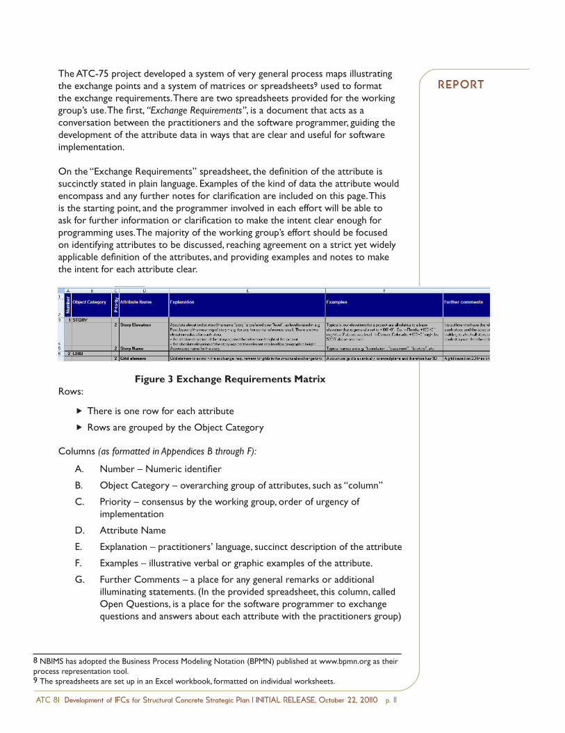
On the “Exchange Requirements” spreadsheet, the definition of the attribute is succinctly stated in plain language. Examples of the kind of data the attribute would encompass and any further notes for clarification are included on this page. This is the starting point, and the programmer involved in each effort will be able to ask for further information or clarification to make the intent clear enough for programming uses. The majority of the working group’s effort should be focused on identifying attributes to be discussed, reaching agreement on a strict yet widely applicable definition of the attributes, and providing examples and notes to make the intent for each attribute clear.
Figure 3 Exchange Requirements MatrixRows:
There is one row for each attribute
Rows are grouped by the Object Category
Columns (as formatted in Appendices B through F):
Number – Numeric identifier
Object Category – overarching group of attributes, such as “column”
Priority – consensus by the working group, order of urgency of implementation
Attribute Name
Explanation – practitioners’ language, succinct description of the attribute
Examples – illustrative verbal or graphic examples of the attribute.
Further Comments – a place for any general remarks or additional illuminating statements. (In the provided spreadsheet, this column, called Open Questions, is a place for the software programmer to exchange questions and answers about each attribute with the practitioners group)
Ñ
Ñ
A.
B.
C.
D.
E.
F.
G.
8 NBIMS has adopted the Business Process Modeling Notation (BPMN) published at www.bpmn.org as their process representation tool.9 The spreadsheets are set up in an Excel workbook, formatted on individual worksheets.
ATC 81 Development of IFCs for Structural Concrete D R A F TStrategic Plan September 15, 2010
Page 12
Programming and Design Phase – Exchange Requirement Matrices
The ATC 75 project developed matrices7 (spreadsheets) that provided a bridge of exchangeattributes between practitioners and software programmers, illustrating the fundamental datatypes involved in the exchanges. The matrix is structured to keep the practitioners thinking indiscrete engineering terms, as well as provide the foundation for software programmers totranslate the practitioners’ data groups into the programming language necessary for softwareimplementation. For each goal, an attributes spreadsheet (see Appendices) has been started toseed the discussion; again, the working group is challenged to tailor and expand the attributeslisted as they see fit. The working group will also be responsible for defining the process maps8
that illustrate the business use cases for the exchanges.
In order to guide discussion and output toward an end product that will be easy to integrate tosoftware, each working group will need to retain a software programmer or consultant familiarwith IFCs to work with the templates provided and establish the IFC binding to correspond withthe exchange requirements.
The ATC 75 project developed a system of very general process maps illustrating the exchangepoints and a system of matrices or spreadsheets9 used to format the exchange requirements.There are two spreadsheets provided for the working group’s use. The first, “ExchangeRequirements”, is a document that acts as a conversation between the practitioners and thesoftware programmer, guiding the development of the attribute data in ways that are clear anduseful for software implementation.
On the “Exchange Requirements” spreadsheet, the definition of the attribute is succinctly statedin plain language. Examples of the kind of data the attribute would encompass and any furthernotes for clarification are included on this page. This is the starting point, and the programmerinvolved in each effort will be able to ask for further information or clarification to make theintent clear enough for programming uses. The majority of the working group’s effort should befocused on identifying attributes to be discussed, reaching agreement on a strict yet widelyapplicable definition of the attributes, and providing examples and notes to make the intent foreach attribute clear.
Figure 3 Exchange Requirements Matrix
Rows:There is one row for each attribute
7 Information Delivery Manual (IDM), Exchange Requirements (ERs) and IFC Binding8 NBIMS has adopted the Business Process Modeling Notation (BPMN) published at www.bpmn.org as theirprocess representation tool.9 The spreadsheets are set up in an Excel workbook, formatted on individual worksheets.
ATC 81 Development of IFCs for Structural Concrete Strategic Plan | INITIAL RELEASE, October 22, 20110 p. 12
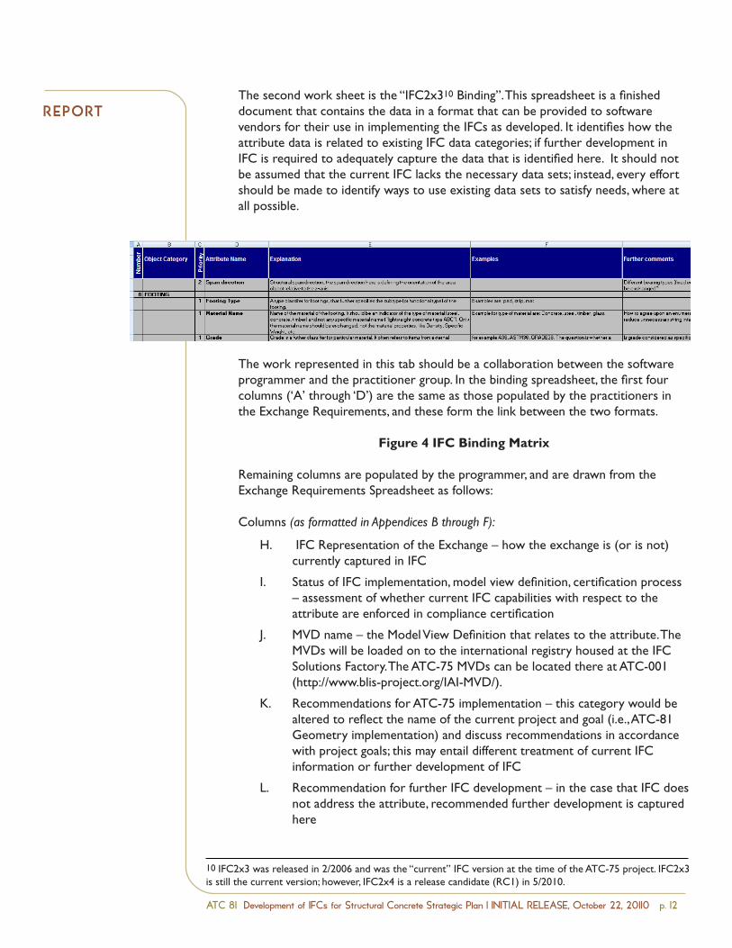
RepoRtThe second work sheet is the “IFC2x310 Binding”. This spreadsheet is a finished document that contains the data in a format that can be provided to software vendors for their use in implementing the IFCs as developed. It identifies how the attribute data is related to existing IFC data categories; if further development in IFC is required to adequately capture the data that is identified here. It should not be assumed that the current IFC lacks the necessary data sets; instead, every effort should be made to identify ways to use existing data sets to satisfy needs, where at all possible.
The work represented in this tab should be a collaboration between the software programmer and the practitioner group. In the binding spreadsheet, the first four columns (‘A’ through ‘D’) are the same as those populated by the practitioners in the Exchange Requirements, and these form the link between the two formats.
Figure 4 IFC Binding Matrix
Remaining columns are populated by the programmer, and are drawn from the Exchange Requirements Spreadsheet as follows:
Columns (as formatted in Appendices B through F):
IFC Representation of the Exchange – how the exchange is (or is not) currently captured in IFC
Status of IFC implementation, model view definition, certification process – assessment of whether current IFC capabilities with respect to the attribute are enforced in compliance certification
MVD name – the Model View Definition that relates to the attribute. The MVDs will be loaded on to the international registry housed at the IFC Solutions Factory. The ATC-75 MVDs can be located there at ATC-001 (http://www.blis-project.org/IAI-MVD/).
Recommendations for ATC-75 implementation – this category would be altered to reflect the name of the current project and goal (i.e., ATC-81 Geometry implementation) and discuss recommendations in accordance with project goals; this may entail different treatment of current IFC information or further development of IFC
Recommendation for further IFC development – in the case that IFC does not address the attribute, recommended further development is captured here
H.
I.
J.
K.
L.
ATC 81 Development of IFCs for Structural Concrete D R A F TStrategic Plan September 15, 2010
Page 13
Rows are grouped by the Object Category
Columns (as formatted in Appendices B through F):A. Number – Numeric identifierB. Object Category – overarching group of attributes, such as “column”C. Priority – consensus by the working group, order of urgency of implementationD. Attribute NameE. Explanation – practitioners’ language, succinct description of the attributeF. Examples – illustrative verbal or graphic examples of the attribute.G. Further Comments – a place for any general remarks or additional illuminating
statements. (In the provided spreadsheet, this column, called Open Questions, is a placefor the software programmer to exchange questions and answers about each attributewith the practitioners group.)
The second work sheet is the “IFC2x310 Binding”. This spreadsheet is a finished document thatcontains the data in a format that can be provided to software vendors for their use inimplementing the IFCs as developed. It identifies how the attribute data is related to existingIFC data categories; if further development in IFC is required to adequately capture the data thatis identified here. The work represented in this tab should be a collaboration between thesoftware programmer and the practitioner group. In the binding spreadsheet, the first fourcolumns (‘A’ through ‘D’) are the same as those populated by the practitioners in the ExchangeRequirements, and these form the link between the two formats.
Figure 4 IFC Binding Matrix
Remaining columns are populated by the programmer, and are drawn from the ExchangeRequirements Spreadsheet as follows:
Columns (as formatted in Appendices B through F):H. IFC Representation of the Exchange – how the exchange is (or is not) currently captured
in IFCI. Status of IFC implementation, model view definition, certification process – assessment
of whether current IFC capabilities with respect to the attribute are enforced incompliance certification
J. MVD name – the Model View Definition that relates to the attribute. The MVDs will beloaded on to the international registry housed at the IFC Solutions Factory. The ATC 75MVDs can be located there at ATC 001 (http://www.blis project.org/IAI MVD/).
K. Recommendations for ATC 75 implementation – this category would be altered toreflect the name of the current project and goal (i.e., ATC 81 Geometry implementation)
10 IFC2x3 was released in 2/2006 and was the “current” IFC version at the time of the ATC 75 project. IFC2x3 is stillthe current version; however, IFC2x4 is a release candidate (RC1) in 5/2010.
10 IFC2x3 was released in 2/2006 and was the “current” IFC version at the time of the ATC-75 project. IFC2x3 is still the current version; however, IFC2x4 is a release candidate (RC1) in 5/2010.
ATC 81 Development of IFCs for Structural Concrete Strategic Plan | INITIAL RELEASE, October 22, 20110 p. 1�
RepoRtThe full workbook has been provided as Appendix B, which represents the matured work of the earlier ATC-75 project and shows an example of how this work process is to be utilized. In that workbook, the “IFC Implementation” tab is a reporting tool for the software vendors involved to document their implementation of each of the attributes discussed. The “Figs” tabs hold examples of the intended data to be captured in each attribute, meant as reference for the programmers and possibly to be provided to practitioners.
The Appendices provided with this plan contain a “starter” working document, populated with suggested attributes. The software programmer involved with each Goal should create the additional tabs contained in the example workbook, suited to the attributes the working group chooses to address, in order to mature the work to the level required for making any changes to the IFC format.
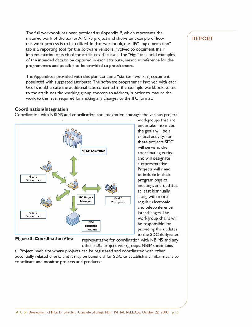
Coordination/IntegrationCoordination with NBIMS and coordination and integration amongst the various project
workgroups that are undertaken to meet the goals will be a critical activity. For these projects SDC will serve as the coordinating entity and will designate a representative. Projects will need to include in their program physical meetings and updates, at least biannually, along with more regular electronic and teleconference interchanges. The workgroup chairs will be responsible for providing the updates to the SDC designated
representative for coordination with NBIMS and any other SDC project workgroups. NBIMS maintains
a “Project” web site where projects can be registered and coordinated with other potentially related efforts and it may be beneficial for SDC to establish a similar means to coordinate and monitor projects and products.
ATC 81 Development of IFCs for Structural Concrete D R A F TStrategic Plan September 15, 2010
Page 14
and discuss recommendations in accordance with project goals; this may entail differenttreatment of current IFC information or further development of IFC
L. Recommendation for further IFC development – in the case that IFC does not addressthe attribute, recommended further development is captured here
The full workbook has been provided as Appendix B, which represents the matured work of theearlier ATC 75 project and shows an example of how this work process is to be utilized. In thatworkbook, the “IFC Implementation” tab is a reporting tool for the software vendors involved todocument their implementation of each of the attributes discussed. The “Figs” tabs holdexamples of the intended data to be captured in each attribute, meant as reference for theprogrammers and possibly to be provided to practitioners.
The Appendices provided with this plan contain a “starter” working document, populated withsuggested attributes. The software programmer involved with each Goal should create theadditional tabs contained in the example workbook, suited to the attributes the working groupchooses to address, in order to mature the work to the level required for making any changes tothe IFC format.
Coordination/IntegrationCoordination with NBIMS and coordination and integration amongst the various project workgroupsthat are undertaken to meet the goals will be a critical activity. For these projects SDC will serve as thecoordinating entity and will designate a representative. Projects will need to include in their programphysical meetings and updates, at least biannually, along with more regular electronic andteleconference interchanges. The workgroup chairs will be responsible for providing the updates to the
SDC designated representative forcoordination with NBIMS and anyother SDC project workgroups.NBIMS maintains a “Project” web sitewhere projects can be registered andcoordinated with other potentiallyrelated efforts and it may bebeneficial for SDC to establish asimilar means to coordinate andmonitor projects and products.
Figure 5: Coordination ViewFigure 5: Coordination View
RepoRtS t R at e g I C p l a n
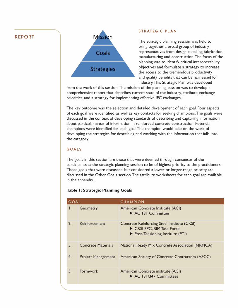
The strategic planning session was held to bring together a broad group of industry representatives from design, detailing, fabrication, manufacturing and construction. The focus of the planning was to identify critical interoperability objectives and formulate a strategy to increase the access to the tremendous productivity and quality benefits that can be harnessed for industry. This Strategic Plan was developed
from the work of this session. The mission of the planning session was to develop a comprehensive report that describes current state of the industry, attribute exchange priorities, and a strategy for implementing effective IFC exchanges.
The key outcome was the selection and detailed development of each goal. Four aspects of each goal were identified, as well as key contacts for seeking champions. The goals were discussed in the context of developing standards of describing and capturing information about particular areas of information in reinforced concrete construction. Potential champions were identified for each goal. The champion would take on the work of developing the strategies for describing and working with the information that falls into the category.
g oa lS
The goals in this section are those that were deemed through consensus of the participants at the strategic planning session to be of highest priority to the practitioners. Those goals that were discussed, but considered a lower or longer-range priority are discussed in the Other Goals section. The attribute worksheets for each goal are available in the appendix.
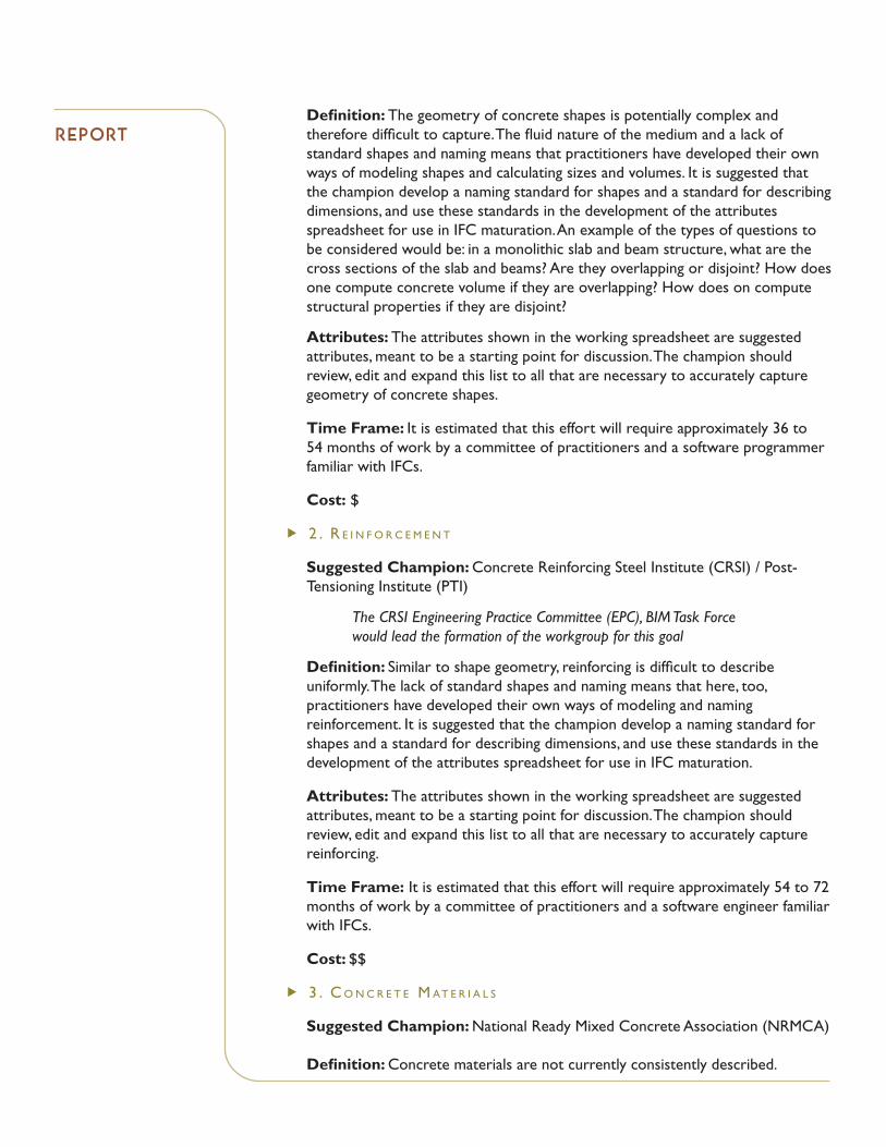
Table 1: Strategic Planning Goals
g oa l C H a m p I o n
1. Geometry American Concrete Institute (ACI)AC 131 CommitteeÑ
2. Reinforcement Concrete Reinforcing Steel Institute (CRSI)CRSI EPC, BIM Task ForcePost-Tensioning Institute (PTI)
ÑÑ
3. Concrete Materials National Ready Mix Concrete Association (NRMCA)
4. Project Management American Society of Concrete Contractors (ASCC)
5. Formwork American Concrete institute (ACI)AC 131/347 CommitteesÑ
ATC 81 Development of IFCs for Structural Concrete D R A F TStrategic Plan September 15, 2010
Page 15
STRATEGIC PLAN
The strategic planning session was held to bring together abroad group of industry representatives from design, detailing,fabrication, manufacturing and construction. The focus of theplanning was to identify critical interoperability objectives andformulate a strategy to increase the access to the tremendousproductivity and quality benefits that can be harnessed forindustry. This Strategic Plan was developed from the work ofthis session. The mission of the planning session was to develop
a comprehensive report that describes current state of the industry, attribute exchange priorities, and astrategy for implementing effective IFC exchanges.
The key outcome was the selection and detailed development of each goal. Four aspects of each goalwere identified, as well as key contacts for seeking champions. The goals were discussed in the contextof developing standards of describing and capturing information about particular areas of information inreinforced concrete construction. Potential champions were identified for each goal. The championwould take on the work of developing the strategies for describing and working with the informationthat falls into the category.
GOALS
The goals in this section are those that were deemed through consensus of the participants at thestrategic planning session to be of highest priority to the practitioners. Those goals that were discussed,but considered a lower or longer range priority are discussed in the Other Goals section. The attributeworksheets for each goal are available in the appendix.
Table 1: Strategic Planning Goals
GOAL CHAMPION1. Geometry American Concrete Institute (ACI)2. Reinforcement Concrete Reinforcing Steel Institute (CRSI)3. Concrete Materials National Ready Mixed Concrete Association
(NRMCA)4. Project Management
Quantity/EstimationSchedule/Sequence
American Society of Professional Estimators(ASPE)American Society of Concrete Contractors(ASCC)
5. Formwork American Concrete Institute (ACI)
The time it takes to fulfill the successful completion of each of these goals will be dependent on manyfactors, chief among them are the availability and commitment of industry subject matter experts, IFCconsultants and funding levels to support development. In broad strokes it is estimated that each ofthese goals will take between 36 to 54 months to execute. These general time frames assume only avery limited funding level to support a largely volunteer process. These durations could be substantiallyshortened if funding is available to drive a faster paced and more directed process, which would be thedesired means of executing the strategic plan. There is also a level of interdependency between these
Mission
Goals
Strategies
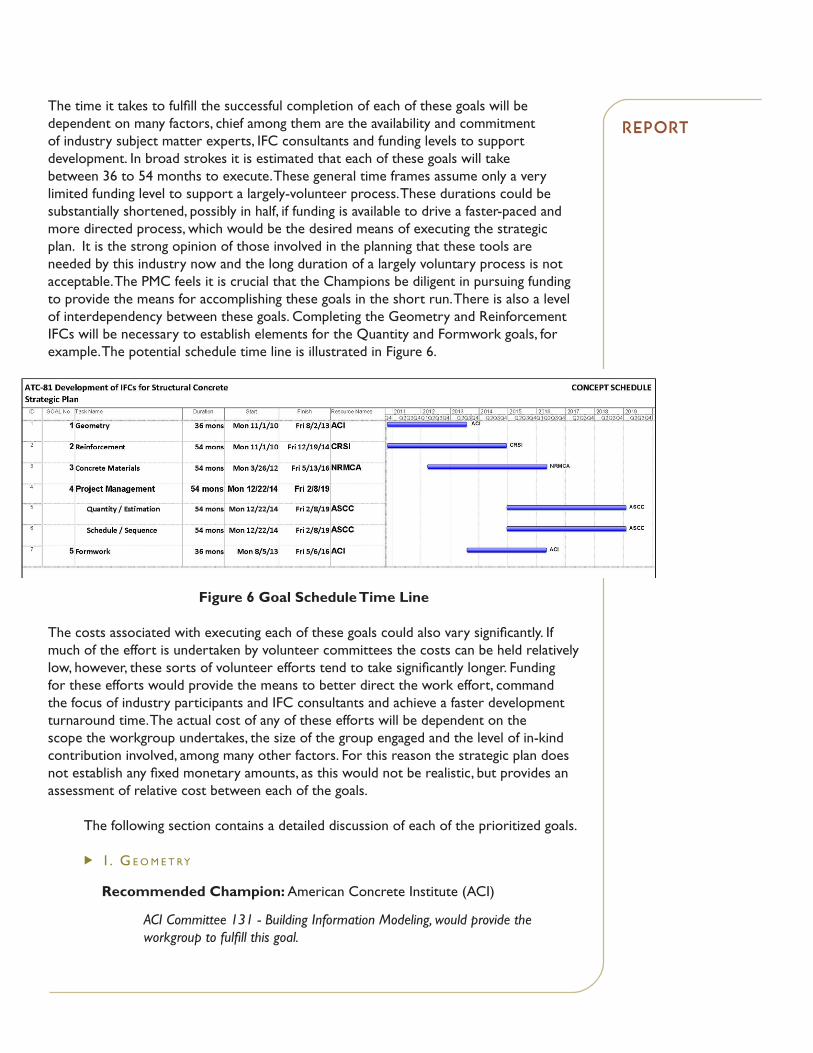
The time it takes to fulfill the successful completion of each of these goals will be dependent on many factors, chief among them are the availability and commitment of industry subject matter experts, IFC consultants and funding levels to support development. In broad strokes it is estimated that each of these goals will take between 36 to 54 months to execute. These general time frames assume only a very limited funding level to support a largely-volunteer process. These durations could be substantially shortened, possibly in half, if funding is available to drive a faster-paced and more directed process, which would be the desired means of executing the strategic plan. It is the strong opinion of those involved in the planning that these tools are needed by this industry now and the long duration of a largely voluntary process is not acceptable. The PMC feels it is crucial that the Champions be diligent in pursuing funding to provide the means for accomplishing these goals in the short run. There is also a level of interdependency between these goals. Completing the Geometry and Reinforcement IFCs will be necessary to establish elements for the Quantity and Formwork goals, for example. The potential schedule time line is illustrated in Figure 6.
Figure 6 Goal Schedule Time Line
The costs associated with executing each of these goals could also vary significantly. If much of the effort is undertaken by volunteer committees the costs can be held relatively low, however, these sorts of volunteer efforts tend to take significantly longer. Funding for these efforts would provide the means to better direct the work effort, command the focus of industry participants and IFC consultants and achieve a faster development turnaround time. The actual cost of any of these efforts will be dependent on the scope the workgroup undertakes, the size of the group engaged and the level of in-kind contribution involved, among many other factors. For this reason the strategic plan does not establish any fixed monetary amounts, as this would not be realistic, but provides an assessment of relative cost between each of the goals.
The following section contains a detailed discussion of each of the prioritized goals.
u I .. G e o m e t ry
Recommended Champion: American Concrete Institute (ACI)
ACI Committee 131 - Building Information Modeling, would provide the workgroup to fulfill this goal.
RepoRt
Definition: The geometry of concrete shapes is potentially complex and therefore difficult to capture. The fluid nature of the medium and a lack of standard shapes and naming means that practitioners have developed their own ways of modeling shapes and calculating sizes and volumes. It is suggested that the champion develop a naming standard for shapes and a standard for describing dimensions, and use these standards in the development of the attributes spreadsheet for use in IFC maturation. An example of the types of questions to be considered would be: in a monolithic slab and beam structure, what are the cross sections of the slab and beams? Are they overlapping or disjoint? How does one compute concrete volume if they are overlapping? How does on compute structural properties if they are disjoint?
Attributes: The attributes shown in the working spreadsheet are suggested attributes, meant to be a starting point for discussion. The champion should review, edit and expand this list to all that are necessary to accurately capture geometry of concrete shapes.
Time Frame: It is estimated that this effort will require approximately 36 to 54 months of work by a committee of practitioners and a software programmer familiar with IFCs.
Cost: $
u 2 .. r e I n f o r c e m e n t
Suggested Champion: Concrete Reinforcing Steel Institute (CRSI) / Post-Tensioning Institute (PTI)
The CRSI Engineering Practice Committee (EPC), BIM Task Force would lead the formation of the workgroup for this goal
Definition: Similar to shape geometry, reinforcing is difficult to describe uniformly. The lack of standard shapes and naming means that here, too, practitioners have developed their own ways of modeling and naming reinforcement. It is suggested that the champion develop a naming standard for shapes and a standard for describing dimensions, and use these standards in the development of the attributes spreadsheet for use in IFC maturation.
Attributes: The attributes shown in the working spreadsheet are suggested attributes, meant to be a starting point for discussion. The champion should review, edit and expand this list to all that are necessary to accurately capture reinforcing.
Time Frame: It is estimated that this effort will require approximately 54 to 72 months of work by a committee of practitioners and a software engineer familiar with IFCs.
Cost: $$
u 3 .. c o n c r e t e . m at e r I a l S
Suggested Champion: National Ready Mixed Concrete Association (NRMCA)
Definition: Concrete materials are not currently consistently described.
RepoRt
Although there are aspects of the concrete mix that are considered to be proprietary information, a general description can be developed that specifies the mix either by aggregate type and ratio, strength, slump, air, water, supplementary cementing materials (SCM), cure time, CO2 (Green House Gas), aggregate type(s), ad-mixtures and any number of other important variables that will need to be specified, tracked or segregated for engineering, QA-QC, take-off/estimating or other documentation. It is suggested that the champion determine what type of information needs to be conveyed and a method for describing concrete materials that can be consistently implemented by practitioners.
Attributes: The attributes shown in the working spreadsheet are suggested attributes, meant to be a starting point for discussion. The champion should review, edit and expand this list to all that are necessary to accurately capture adequate description of concrete materials.
Time Frame: It is estimated that this effort will require approximately 54 to 72 months of work by a committee of practitioners and a software engineer familiar with IFCs.
Cost: $$
u 4 .. p r o j e c t . m a n a G e m e n t
A. Quantity/Estimation
Suggested Champion: American Society of Concrete Contractors (ASCC)
Definition: Quantity estimation for CIP structural concrete should work to incorporate all of the elements that go into the final permanent concrete structure. This may include the concrete, reinforcing bar, post tension tendons, headed shear stud reinforcement, water-stop, embeds, penetrations and other items. It will also be desirable to have form work, scaffolding, and other temporary but essential components of the structural concrete installation included.
Quantities of permanent materials, temporary materials, and labor must be location-specific and traceable.
Quantity should not be limited to the material components. Labor is many times an even more variable and critical cost component to the estimating process. It is all-important that the geometry replicate the sequence of work and build the model based upon the accurate stop-start sequences of work. This will allow the model to account for (and depict if desired) the sequence of work that takes place on the project. This is a key element of the modeling process that applies to all efforts, but is critical for the labor and constructability components of the Project Management scope.
Attributes: The attributes shown in the working spreadsheet are suggested attributes, meant to be a starting point for discussion. The champion should review, edit and expand this list to all that are necessary to accurately capture quantity and estimating data.
RepoRt
Time Frame: It is estimated that this effort will require approximately 54 to 72 months of work by a committee of practitioners and a software programmer familiar with IFCs.
Cost: $$$
B. Schedule/Sequence (See Quantity/Estimation)
Suggested Champion: American Society of Concrete Contractors (ASCC)
Definition: By standardizing the naming, geometry and quantity data types for concrete and rebar shapes practitioners can add additional user defined attributes which will allow for scheduling, sequencing, consumption and resources information to be attached to the geometry, which in turn can be used to schedule and sequence construction, fabrication, facilities management and maintenance. It is suggested that the champion develop scheduling and sequencing standards for describing CIP concrete elements in the development of the attributes spreadsheet for use in IFC maturation.
Attributes: The attributes shown in the working spreadsheet are suggested attributes, meant to be a starting point for discussion. The champion should review, edit and expand this list to all that are necessary to accurately capture quantity and estimating data.
Time Frame: It is estimated that this effort will require approximately 54 to 72 months of work by a committee of practitioners and a software programmer familiar with IFCs.
Cost: $$$
u 5 .. f o r m w o r k
Suggested Champion: American Concrete Institute (ACI)
ACI Committee 131 - Building Information Modeling, in conjunction with the support of ACI Committee 347 - Formwork for Concrete, would provide the workgroup to fulfill this goal.
Definition: Formwork determines a great deal of the construction process and cost for any project. A uniform method of describing formwork is needed in order for BIM software to intelligently handle the data. Shapes, finishes and supports are among the categories of data for which the champion would develop standards and descriptions.
Attributes: The attributes shown in the working spreadsheet are suggested attributes, meant to be a starting point for discussion. The champion should review, edit and expand this list to all that are necessary to accurately capture quantity and estimating data.
Time Frame: It is estimated that this effort will require approximately 36 to 54 months of work by a committee of practitioners and a software programmer familiar with IFCs.
Cost: $$
RepoRt
ATC 81 Development of IFCs for Structural Concrete Strategic Plan | INITIAL RELEASE, October 22, 20110 p. 1�
ot H e R g oa lS
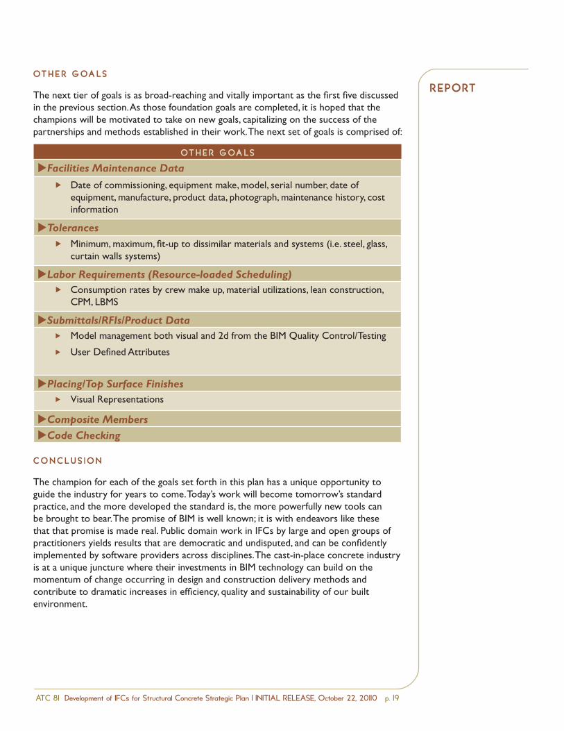
The next tier of goals is as broad-reaching and vitally important as the first five discussed in the previous section. As those foundation goals are completed, it is hoped that the champions will be motivated to take on new goals, capitalizing on the success of the partnerships and methods established in their work. The next set of goals is comprised of:
ot H e R g oa lS
uFacilities Maintenance Data
Date of commissioning, equipment make, model, serial number, date of equipment, manufacture, product data, photograph, maintenance history, cost information
Ñ
uTolerancesMinimum, maximum, fit-up to dissimilar materials and systems (i.e. steel, glass, curtain walls systems)
Ñ
uLabor Requirements (Resource-loaded Scheduling)Consumption rates by crew make up, material utilizations, lean construction, CPM, LBMS
Ñ
uSubmittals/RFIs/Product DataModel management both visual and 2d from the BIM Quality Control/Testing
User Defined Attributes
Ñ
Ñ
uPlacing/Top Surface FinishesVisual RepresentationsÑ
uComposite MembersuCode Checking
C o n C l u S I o n
The champion for each of the goals set forth in this plan has a unique opportunity to guide the industry for years to come. Today’s work will become tomorrow’s standard practice, and the more developed the standard is, the more powerfully new tools can be brought to bear. The promise of BIM is well known; it is with endeavors like these that that promise is made real. Public domain work in IFCs by large and open groups of practitioners yields results that are democratic and undisputed, and can be confidently implemented by software providers across disciplines. The cast-in-place concrete industryis at a unique juncture where their investments in BIM technology can build on the momentum of change occurring in design and construction delivery methods and contribute to dramatic increases in efficiency, quality and sustainability of our built environment.
RepoRt

a p p e n D I X a : Project Reference Links
a p p e n D I X b : Example Exchange Requirements Workbook, ATC-75
a p p e n D I X C : Geometry Attributes Matrix
a p p e n D I X D : Reinforcement Attributes Matrix
a p p e n D I X e : Concrete Materials Attributes Matrix
a p p e n D I X f : Project Management Attributes Matrix
a p p e n D I X g : Formwork Attributes Matrix
appenDICeS
appenDIX a:pro ject
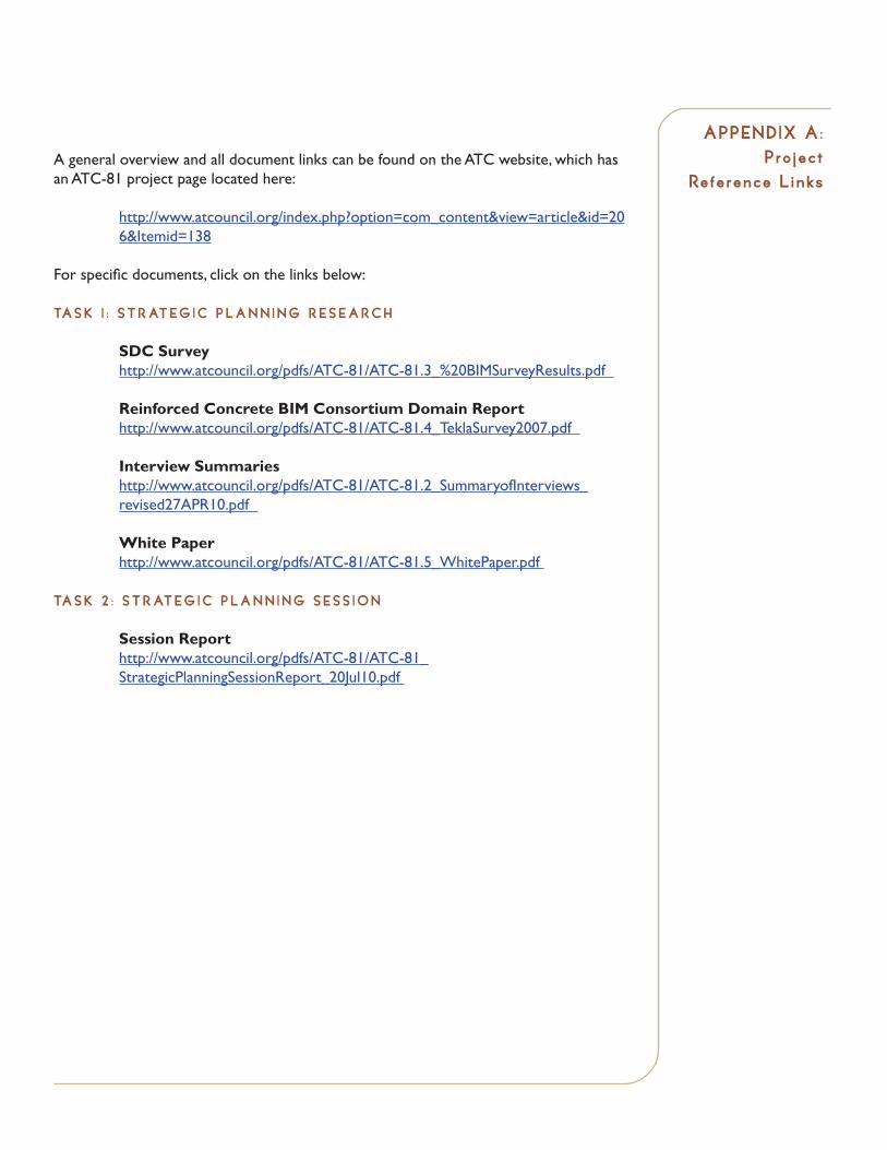
Reference l inksA general overview and all document links can be found on the ATC website, which has an ATC-81 project page located here:
http://www.atcouncil.org/index.php?option=com_content&view=article&id=206&Itemid=138
For specific documents, click on the links below:
ta S K 1 : S t R at e g I C p l a n n I n g R e S e a R C H
SDC Survey http://www.atcouncil.org/pdfs/ATC-81/ATC-81.3_%20BIMSurveyResults.pdf
Reinforced Concrete BIM Consortium Domain Report http://www.atcouncil.org/pdfs/ATC-81/ATC-81.4_TeklaSurvey2007.pdf
Interview Summaries http://www.atcouncil.org/pdfs/ATC-81/ATC-81.2_SummaryofInterviews_revised27APR10.pdf
White Paper http://www.atcouncil.org/pdfs/ATC-81/ATC-81.5_WhitePaper.pdf
ta S K 2 : S t R at e g I C p l a n n I n g S e S S I o n
Session Report http://www.atcouncil.org/pdfs/ATC-81/ATC-81_StrategicPlanningSessionReport_20Jul10.pdf

a D D I t I o n a l R e f e R e n C e S
American Concrete Institute www.concrete.org
American Society of Concrete Contractors www.ascconline.org
American Society of Professional Estimators www.aspenational.org
Applied Technology Council www.atcouncil.org
ATC-75 Development of IFCs for the Structural Domain http://www.atcouncil.org/index.php?option=com_content&view=article&id=92&Itemid=54
Building Smart Alliance www.buildingsmartalliance.org
Charles Pankow Foundation http://www.pankowfoundation.org
IFC Solutions Factory http://www.blis-project.org/IAI-MVD
National BIM Standard http://www.buildingsmartalliance.org/index.php/nbims
National Ready Mixed Concrete Association www.nrmca.org
OmniClass http://www.omniclass.org
RMC Research & Education Foundation http://www.rmc-foundation.org
Strategic Development Council http://www.concretesdc.org
appenDIX a:pro ject
Reference l inks

appenDIX b :example
exchange Requ i rements
Workbook , atC-75
ATC‐75 IFCs for the Structural DomainExchange Requirements
Date: 9/19/08Version 1.2
Object Category Attribute Name Explanation Examples Further comments
1 STORY2 Story Elevation Absolute elevation for story (the name "story" is prefered over "level", as level is used in e.g. Revit
beyond the meaning of story - e.g. for any horizontal reference level). There are two elevation valuesfor each story:- the relative elevation of the story against the reference height of the project.- the absolute elevation of the story against the relevant sea level (or geographic height datum)
Typically, our elevations for a project are all relative to a base elevation that is generally set to +100'-0". So, in Florida, +100'-0'" might be 3' above sea level. In Denver, Colorado, +100'-0" might be 5300' above sea level.
It is sufficient to have the relative elevation as an explicit measure for each story, and the absolute "above see level" elevation once at the building to which all stories references. The absolute elevation of each story can then be calculated by the receiving system.
2 Story Name Associated name for the story Typical names are e.g. "foundation", "basement", "1st story", etc. 2 GRID
2 Grid element Grid element to exists in the exchange, requirement for grids in the structural exchange is to have a 3D grid, based on grid planes.
A structural grid is a vertically-oriented plane and therefore has 3D characteristics. A grid system is a collection of 3D planes. However this could be simulated by multiple 2D grids assigned to the stories in a building.
A grid based on 2D lines on a base plane is already needed in the exchange. A full 3D grid based on planes, rather then lines, is not widely supported by software. So 2D lines are sufficient but must be in multiple grid planes (at varying elevations) that define levels in order to get a "3D grid"
2 Grid layout Geometric layout of the grid, set of horizontal and vertical planes with intersection between them.
2 Grid numbering A string attached to each grid plane (or line) representing the plane (or line) label. E.g. "A", "B", "1", "2", etc.2 Reference to story Reference to the story where the grid planes (or lines) appears on. The 2D gid is assigned to each story where it is valid. For now, it is
necessary to copy the grid to each story. 3 COLUMN
1 Column axis Definition axis of the column, used e.g. for determining the Cardinal point and as a first assumption for the linear structural member representing the column for structural analysis.
1 Profile Name Name of the profile (or cross section) of the column. The naming convention, when applicable, should follow AISC naming convention.
Profile name is a string that represents a standard naming convention from a manual, handbook, or other external references. It is common in steel industry by using a AISC or CISC standard profile name. Some precast profiles have standard naming conventions, but most concrete profiles are not standarized. Name examples are (W14X90, 24X24).
For non-AISC profiles, is it required to also pass the profile table (or profile standard) name. Currently the best way to pass the profile information is by including it into a property set.
1 Material Name Name of the material of the column. It should be an indicator of the type of material (steel, concrete, timber) and not any specific material name ("lightweight concrete type ABC"). Only the material name should be exchanged, not the material properties, like Density, Specific Weight, etc.
Example for type of material are: Concrete, steel, timber, glass We need to agree upon an enumeration of applicable type of material to reduce unecessary string interpretation.
1 Grade Grade is a futher classifier for particular material. It often refers to items from external standards such as ASTM e.g. ASTM 36.
for example A36, ASTM36, GRADE36. The question is whether a standard expression is available. Receiving applicaion therefore must be cabale to interpret all kinds of expressions.
Is grade considered as specific property of material, or of the element (or profile)? Is just a grade value sufficient, or a value with reference to a standard?
1 Length Member length, it is software generated value that may be redundent to the length parameter embedded in the geometry representation.There are different length measurements, best described as quantities:- logical length between two joints- physical length of the actual column bodySince these can be redundent to the geometry representation it is importent to keep them consistent and to guarantee that there is no inconsistency. They are provided in addition to the geometric representation.
The logical length is a real length measure between the two joints and equal to the length of the column axis. The physical length is the length of the extrusion body (not taking cut-out's etc. into account). Having explicit real values is particularly important, if the geometry is not an extrusion (e.g. a boundary representation).
Is there a specific definition of how the length is measured? Is it the physical or cut length, or the logical length between two joints?
1 Roll Member roll, software generated value that may be redundent to the placement and placement orientation parameters embedded in the geometric representation.Roll is the rotation of the column profile (and body) about a vertical axis for columns. Since these can be redundent to the geometry representation it is importent to keep them consistent and to guarantee that there is no inconsistency. They are provided in addition to the geometric representation.
For example, for a 24x30 cast-in-place column, you have to know the orientation or roll of the column to know if the 30" dimension is pointing along x-axis or the y-axis (or somewhere in between).
Roll is handled for analytical models, but not (yet) for physical models, is it needed for physical models as well?
1 Cardinal point Offset of profile from longitudinal axis, essentially, it is the justification of the cross-section relatively to the working line between the two end joints.Note: propose to rename it from insertion point to cardinal point (to make it similar to the CIS/2 concept).
Cardinal point "lower-left", "center-right", etc.
1 Element ID Unique identifier for elementNote: Element ID is only for indexing model elements and used to uniquely identify elements that may have identical properties (length, profile, etc.). Element ID is typically defined by the modeling tool and the user should not be able to change this to ensure uniqueness.
is it a piecemark for structural steel? However, piecemarks are not necessarily unique across the entire model. Their might be many identical assemblies with the same parts with the same piecemarks. Or is it a GUID -a unique software ID that keeps identify across applications?
Prio
ri ty
Num
ber
File: H:\ND1000 ATC-81 IFC for Concrete\Admin\Task 3 Strategic Plan\Backup Documents\Appendix B - Example Exchange Requirements Workbook, ATC-75 Page 1 of 5
ATC‐75 IFCs for the Structural DomainExchange Requirements
Date: 9/19/08Version 1.2
Object Category Attribute Name Explanation Examples Further comments
Prio
rity
Num
ber
2 Schedule Mark Identifier for scheduling same profile elementsNote: Schedule marks do not need to be unique. Schedule mark is typically defined by the user and named based on the elements location on a grid and/or the properties of that element (depth, length, number of reinforcing bars, etc.).
This is generally a short string that is provided on a plan adjacent to a column (for example "CC12"). The "CC12" is then defined in the column schedule. It is generally used as a unique identifier in the plans. So, a CC12 would be at a specific gridline (or gridlines) and is not the same as a CC11 or other mark.
Unsure whether this is different to the ELEMENT ID and if both identifiers are needed.
2 Base Reference Story Base location, reference to the story where the start point of the column resists. Start point is the lower point of the column axis.
This is e.g. a level as defined in "0. Level", from which the member starts.could we have an example drawing? CLICK FOR SCREEN SHOT EXPLANATION
2 Top Reference Story Top location, reference to the story where the end point of the column resists. End point is the upper point of the column axis.
This is e.g. a level as defined in "0. Level", at which the member ends.could we have an example drawing? CLICK FOR SCREEN SHOT EXPLANATION
2 Base Offset Offset from base level This is a length describing the distance above a given level where a column starts. For example, steel columns when spliced are generally cut ~4'-0" above a floor level. So, the column above the splice would have a +4'-0" offset at its start.
Does this information has to be exchanged as redundent additional offset value, as it is already captured in the column position.
2 Top Offset Offset from top level Also a length. In the example in the cell above, the lower column would have a top offset of +4'-0".
Does this information has to be exchanged as redundent additional offset value, as it is already captured in the column position and column geometry.
4 BEAM1 Beam Axis Definition axis of the beam, used e.g. for determining the Cardinal point and as a first assumption
for the linear structural member representing the column for structural analysis.1 Profile Name Name of the profile (or cross section) of the beam. The naming convention, when applicable, should
follow AISC naming convention.Profile name is a string that represents a standard naming convention from a manual, handbook, or other external references. It is common in steel industry by using a AISC or CISC standard profile name. Some precast profiles have standard naming conventions, but most concrete profiles are not standarized. Name examples are (W14X90, 24X24).
For non-AISC profiles, is it required to also pass the profile table (or profile standard) name?
1 Material Name Name of the material of the beam. It should be an indicator of the type of material (steel, concrete, timber) and not any specific material name ("lightweight concrete type ABC"). Only the material name should be exchanged, not the material properties, like Density, Specific Weight, etc.
Example for type of material are: Concrete, steel, timber, glass How to agree upon an enumeration of applicable type of matierial to reduce unecessary string interpretation?
1 Grade Grade is a futher classifier for particular material. It often refers to items from external standards such as ASTM e.g. ASTM 36.
for example A36, ASTM36, GRADE36. The question is whether a standard expression is available. Receiving applicaion therefore must be cabale to interpret all kinds of expressions.
Is grade considered as specific property of material, or of the element (or profile)? Is just a grade value sufficient, or a value with reference to a standard?
1 Length Member length, it is software generated value that may be redundent to the length parameter embedded in the geometry representation.There are different length measurements, best described as quantities:- logical length between two joints- physical length of the actual column bodySince these can be redundent to the geometry representation it is importent to keep them consistent and to guarantee that there is no inconsistency. They are provided in addition to the geometric representation.
The logical length is a real length measure between the two joints and equal to the length of the column axis. The physical length is the length of the extrusion body (not taking cut-out's etc. into account). Having explicit real values is particularly important, if the geometry is not an extrusion (e.g. a boundary representation).
Is there a specific definition of how the length is measured? Is it the physical or cut length, or the logical length between two joints?
1 Roll Member roll, software generated value that may be redundent to the placement and placement orientation parameters embedded in the geometric representation.Roll is the rotation of the column profile (and body) about a vertical axis for columns. Since these can be redundent to the geometry representation it is importent to keep them consistent and to guarantee that there is no inconsistency. They are provided in addition to the geometric representation.
For example, for a 24x30 cast-in-place column, you have to know the orientation or roll of the column to know if the 30" dimension is pointing along x-axis or the y-axis (or somewhere in between).
Roll is handled for analytical models, but not (yet) for physical models, is it needed for physical models as well?
1 Cardinal point Offset of profile from longitudinal axis, essentially, it is the justification of the cross-section relatively to the working line between the two end joints.Note: propose to rename it from insertion point to cardinal point (to make it similar to the CIS/2 concept).
Cardinal point "lower-left", "center-right", etc.
1 Element ID Unique identifier for elementNote: Element ID is only for indexing model elements and used to uniquely identify elements that may have identical properties (length, profile, etc.). Element ID is typically defined by the modeling tool and the user should not be able to change this to ensure uniqueness.
is it a piecemark for structural steel? However, piecemarks are not necessarily unique across the entire model. Their might be many identical assemblies with the same parts with the same piecemarks. Or is it a GUID -a unique software ID that keeps identify across applications?
File: H:\ND1000 ATC-81 IFC for Concrete\Admin\Task 3 Strategic Plan\Backup Documents\Appendix B - Example Exchange Requirements Workbook, ATC-75 Page 2 of 5
ATC‐75 IFCs for the Structural DomainExchange Requirements
Date: 9/19/08Version 1.2
Object Category Attribute Name Explanation Examples Further comments
Prio
rity
Num
ber
2 Schedule Mark Identifier for scheduling same profile elementsNote: Schedule marks do not need to be unique. Schedule mark is typically defined by the user and named based on the elements location on a grid and/or the properties of that element (depth, length, number of reinforcing bars, etc.).
This is generally a short string that is provided on a plan adjacent to a column (for example "CC12"). The "CC12" is then defined in the column schedule. It is generally used as a unique identifier in the plans. So, a CC12 would be at a specific gridline (or gridlines) and is not the same as a CC11 or other mark.
Unsure whether this is different to the ELEMENT ID and if both identifiers are needed.
2 Base Reference Story Base location, reference to the story where the start point of the beam resists. Start point is the lower point of the column axis.
This is e.g. a level as defined in "0. Level", from which the member starts.
2 Vertical Start Offset Start offset in z direction, Same concept as vertical end offset but for the beam start point. The end offset is measured to the axis (or reference line) of the beam.
See figure for explanation A beam, provided it is horizontal, would have a base offset from the story (distance between it's bottom face and the story level, so what is the vertical start offset as additional value?
2 Vertical End Offset End offset in z direction, vertical end offset is the offset distance of a beam endpoint from the insertion point (cardinal point) of that beam. The end offset is measured to the axis (or reference line) of the beam.
See figure for explanation A beam, provided it is horizontal, would have a base offset from the story (distance between it's bottom face and the story level, so what is the vertical end offset as additional value?
5 BRACE1 Brace Axis Definition axis of the brace, used e.g. for determining the Cardinal point and as a first assumption
for the linear structural member representing the column for structural analysis.1 Profile Name Name of the profile (or cross section) of the beam. The naming convention, when applicable, should
follow AISC naming convention.Profile name is a string that represents a standard naming convention from a manual, handbook, or other external references. It is common in steel industry by using a AISC or CISC standard profile name. Some precast profiles have standard naming conventions, but most concrete profiles are not standarized. Name examples are (W14X90, 24X24).
For non-AISC profiles, is it required to also pass the profile table (or profile standard) name?
1 Material Name Name of the material of the beam. It should be an indicator of the type of material (steel, concrete, timber) and not any specific material name ("lightweight concrete type ABC"). Only the material name should be exchanged, not the material properties, like Density, Specific Weight, etc.
Example for type of material are: Concrete, steel, timber, glass How to agree upon an enumeration of applicable type of matierial to reduce unecessary string interpretation?
1 Grade Grade is a futher classifier for particular material. It often refers to items from external standards such as ASTM e.g. ASTM 36.
for example A36, ASTM36, GRADE36. The question is whether a standard expression is available. Receiving applicaion therefore must be cabale to interpret all kinds of expressions.
Is grade considered as specific property of material, or of the element (or profile)? Is just a grade value sufficient, or a value with reference to a standard?
1 Length Member length, it is software generated value that may be redundent to the length parameter embedded in the geometry representation.There are different length measurements, best described as quantities:- logical length between two joints- physical length of the actual column bodySince these can be redundent to the geometry representation it is importent to keep them consistent and to guarantee that there is no inconsistency. They are provided in addition to the geometric representation.
The logical length is a real length measure between the two joints and equal to the length of the column axis. The physical length is the length of the extrusion body (not taking cut-out's etc. into account). Having explicit real values is particularly important, if the geometry is not an extrusion (e.g. a boundary representation).
Is there a specific definition of how the length is measured? Is it the physical or cut length, or the logical length between two joints?
1 Roll Member roll, software generated value that may be redundent to the placement and placement orientation parameters embedded in the geometric representation.Roll is the rotation of the column profile (and body) about a vertical axis for columns. Since these can be redundent to the geometry representation it is importent to keep them consistent and to guarantee that there is no inconsistency. They are provided in addition to the geometric representation.
For example, for a 24x30 cast-in-place column, you have to know the orientation or roll of the column to know if the 30" dimension is pointing along x-axis or the y-axis (or somewhere in between).
Roll is handled for analytical models, but not (yet) for physical models, is it needed for physical models as well?
1 Cardinal point Offset of profile from longitudinal axis, essentially, it is the justification of the cross-section relatively to the working line between the two end joints.Note: propose to rename it from insertion point to cardinal point (to make it similar to the CIS/2 concept).
Cardinal point "lower-left", "center-right", etc.
1 Element ID Unique identifier for elementNote: Element ID is only for indexing model elements and used to uniquely identify elements that may have identical properties (length, profile, etc.). Element ID is typically defined by the modeling tool and the user should not be able to change this to ensure uniqueness.
is it a piecemark for structural steel? However, piecemarks are not necessarily unique across the entire model. Their might be many identical assemblies with the same parts with the same piecemarks. Or is it a GUID -a unique software ID that keeps identify across applications?
2 Schedule Mark Identifier for scheduling same profile elementsNote: Schedule marks do not need to be unique. Schedule mark is typically defined by the user and named based on the elements location on a grid and/or the properties of that element (depth, length, number of reinforcing bars, etc.).
This is generally a short string that is provided on a plan adjacent to a column (for example "CC12"). The "CC12" is then defined in the column schedule. It is generally used as a unique identifier in the plans. So, a CC12 would be at a specific gridline (or gridlines) and is not the same as a CC11 or other mark.
Unsure whether this is different to the ELEMENT ID and if both identifiers are needed.
2 Base Reference Story Base location, reference to the story where the start point of the brace resists. Start point is the lowerpoint of the brace axis.
This is e.g. a level as defined in "0. Level", from which the member starts.
2 Top Reference Story Top location, reference to the story where the end point of the brace resists. End point is the upper point of the brace axis.
This is e.g. a level as defined in "0. Level", at which the member ends.
File: H:\ND1000 ATC-81 IFC for Concrete\Admin\Task 3 Strategic Plan\Backup Documents\Appendix B - Example Exchange Requirements Workbook, ATC-75 Page 3 of 5
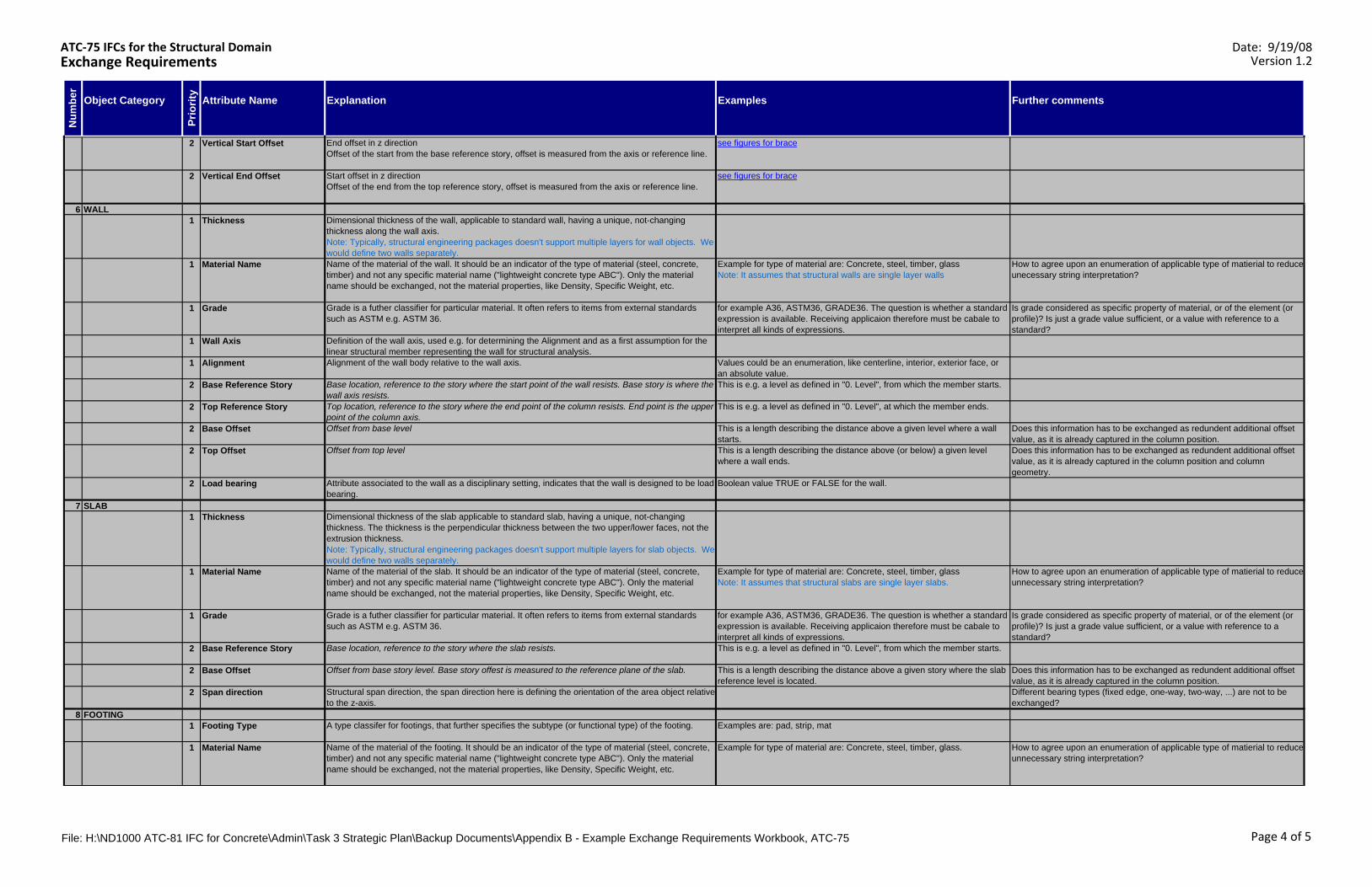
ATC‐75 IFCs for the Structural DomainExchange Requirements
Date: 9/19/08Version 1.2
Object Category Attribute Name Explanation Examples Further comments
Prio
rity
Num
ber
2 Vertical Start Offset End offset in z directionOffset of the start from the base reference story, offset is measured from the axis or reference line.
see figures for brace
2 Vertical End Offset Start offset in z directionOffset of the end from the top reference story, offset is measured from the axis or reference line.
see figures for brace
6 WALL1 Thickness Dimensional thickness of the wall, applicable to standard wall, having a unique, not-changing
thickness along the wall axis.Note: Typically, structural engineering packages doesn't support multiple layers for wall objects. We would define two walls separately.
1 Material Name Name of the material of the wall. It should be an indicator of the type of material (steel, concrete, timber) and not any specific material name ("lightweight concrete type ABC"). Only the material name should be exchanged, not the material properties, like Density, Specific Weight, etc.
Example for type of material are: Concrete, steel, timber, glassNote: It assumes that structural walls are single layer walls
How to agree upon an enumeration of applicable type of matierial to reduce unecessary string interpretation?
1 Grade Grade is a futher classifier for particular material. It often refers to items from external standards such as ASTM e.g. ASTM 36.
for example A36, ASTM36, GRADE36. The question is whether a standard expression is available. Receiving applicaion therefore must be cabale to interpret all kinds of expressions.
Is grade considered as specific property of material, or of the element (or profile)? Is just a grade value sufficient, or a value with reference to a standard?
1 Wall Axis Definition of the wall axis, used e.g. for determining the Alignment and as a first assumption for the linear structural member representing the wall for structural analysis.
1 Alignment Alignment of the wall body relative to the wall axis. Values could be an enumeration, like centerline, interior, exterior face, or an absolute value.
2 Base Reference Story Base location, reference to the story where the start point of the wall resists. Base story is where the wall axis resists.
This is e.g. a level as defined in "0. Level", from which the member starts.
2 Top Reference Story Top location, reference to the story where the end point of the column resists. End point is the upper point of the column axis.
This is e.g. a level as defined in "0. Level", at which the member ends.
2 Base Offset Offset from base level This is a length describing the distance above a given level where a wall starts.
Does this information has to be exchanged as redundent additional offset value, as it is already captured in the column position.
2 Top Offset Offset from top level This is a length describing the distance above (or below) a given level where a wall ends.
Does this information has to be exchanged as redundent additional offset value, as it is already captured in the column position and column geometry.
2 Load bearing Attribute associated to the wall as a disciplinary setting, indicates that the wall is designed to be load bearing.
Boolean value TRUE or FALSE for the wall.
7 SLAB1 Thickness Dimensional thickness of the slab applicable to standard slab, having a unique, not-changing
thickness. The thickness is the perpendicular thickness between the two upper/lower faces, not the extrusion thickness.Note: Typically, structural engineering packages doesn't support multiple layers for slab objects. We would define two walls separately.
1 Material Name Name of the material of the slab. It should be an indicator of the type of material (steel, concrete, timber) and not any specific material name ("lightweight concrete type ABC"). Only the material name should be exchanged, not the material properties, like Density, Specific Weight, etc.
Example for type of material are: Concrete, steel, timber, glassNote: It assumes that structural slabs are single layer slabs.
How to agree upon an enumeration of applicable type of matierial to reduce unnecessary string interpretation?
1 Grade Grade is a futher classifier for particular material. It often refers to items from external standards such as ASTM e.g. ASTM 36.
for example A36, ASTM36, GRADE36. The question is whether a standard expression is available. Receiving applicaion therefore must be cabale to interpret all kinds of expressions.
Is grade considered as specific property of material, or of the element (or profile)? Is just a grade value sufficient, or a value with reference to a standard?
2 Base Reference Story Base location, reference to the story where the slab resists. This is e.g. a level as defined in "0. Level", from which the member starts.
2 Base Offset Offset from base story level. Base story offest is measured to the reference plane of the slab. This is a length describing the distance above a given story where the slab reference level is located.
Does this information has to be exchanged as redundent additional offset value, as it is already captured in the column position.
2 Span direction Structural span direction, the span direction here is defining the orientation of the area object relative to the z-axis.
Different bearing types (fixed edge, one-way, two-way, ...) are not to be exchanged?
8 FOOTING1 Footing Type A type classifer for footings, that further specifies the subtype (or functional type) of the footing. Examples are: pad, strip, mat
1 Material Name Name of the material of the footing. It should be an indicator of the type of material (steel, concrete, timber) and not any specific material name ("lightweight concrete type ABC"). Only the material name should be exchanged, not the material properties, like Density, Specific Weight, etc.
Example for type of material are: Concrete, steel, timber, glass. How to agree upon an enumeration of applicable type of matierial to reduce unnecessary string interpretation?
File: H:\ND1000 ATC-81 IFC for Concrete\Admin\Task 3 Strategic Plan\Backup Documents\Appendix B - Example Exchange Requirements Workbook, ATC-75 Page 4 of 5
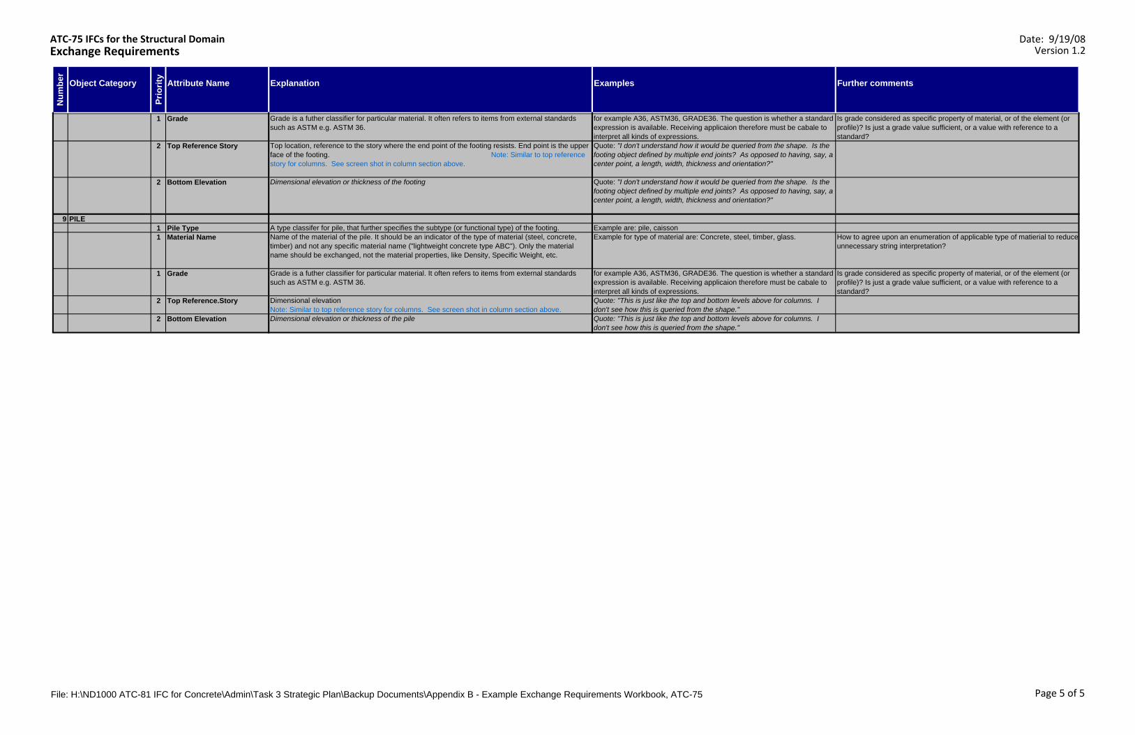
ATC‐75 IFCs for the Structural DomainExchange Requirements
Date: 9/19/08Version 1.2
Object Category Attribute Name Explanation Examples Further comments
Prio
rity
Num
ber
1 Grade Grade is a futher classifier for particular material. It often refers to items from external standards such as ASTM e.g. ASTM 36.
for example A36, ASTM36, GRADE36. The question is whether a standard expression is available. Receiving applicaion therefore must be cabale to interpret all kinds of expressions.
Is grade considered as specific property of material, or of the element (or profile)? Is just a grade value sufficient, or a value with reference to a standard?
2 Top Reference Story Top location, reference to the story where the end point of the footing resists. End point is the upper face of the footing. Note: Similar to top reference story for columns. See screen shot in column section above.
Quote: "I don't understand how it would be queried from the shape. Is the footing object defined by multiple end joints? As opposed to having, say, a center point, a length, width, thickness and orientation?"
2 Bottom Elevation Dimensional elevation or thickness of the footing Quote: "I don't understand how it would be queried from the shape. Is the footing object defined by multiple end joints? As opposed to having, say, a center point, a length, width, thickness and orientation?"
9 PILE1 Pile Type A type classifer for pile, that further specifies the subtype (or functional type) of the footing. Example are: pile, caisson1 Material Name Name of the material of the pile. It should be an indicator of the type of material (steel, concrete,
timber) and not any specific material name ("lightweight concrete type ABC"). Only the material name should be exchanged, not the material properties, like Density, Specific Weight, etc.
Example for type of material are: Concrete, steel, timber, glass. How to agree upon an enumeration of applicable type of matierial to reduce unnecessary string interpretation?
1 Grade Grade is a futher classifier for particular material. It often refers to items from external standards such as ASTM e.g. ASTM 36.
for example A36, ASTM36, GRADE36. The question is whether a standard expression is available. Receiving applicaion therefore must be cabale to interpret all kinds of expressions.
Is grade considered as specific property of material, or of the element (or profile)? Is just a grade value sufficient, or a value with reference to a standard?
2 Top Reference.Story Dimensional elevation Note: Similar to top reference story for columns. See screen shot in column section above.
Quote: "This is just like the top and bottom levels above for columns. I don't see how this is queried from the shape."
2 Bottom Elevation Dimensional elevation or thickness of the pile Quote: "This is just like the top and bottom levels above for columns. I don't see how this is queried from the shape."
File: H:\ND1000 ATC-81 IFC for Concrete\Admin\Task 3 Strategic Plan\Backup Documents\Appendix B - Example Exchange Requirements Workbook, ATC-75 Page 5 of 5
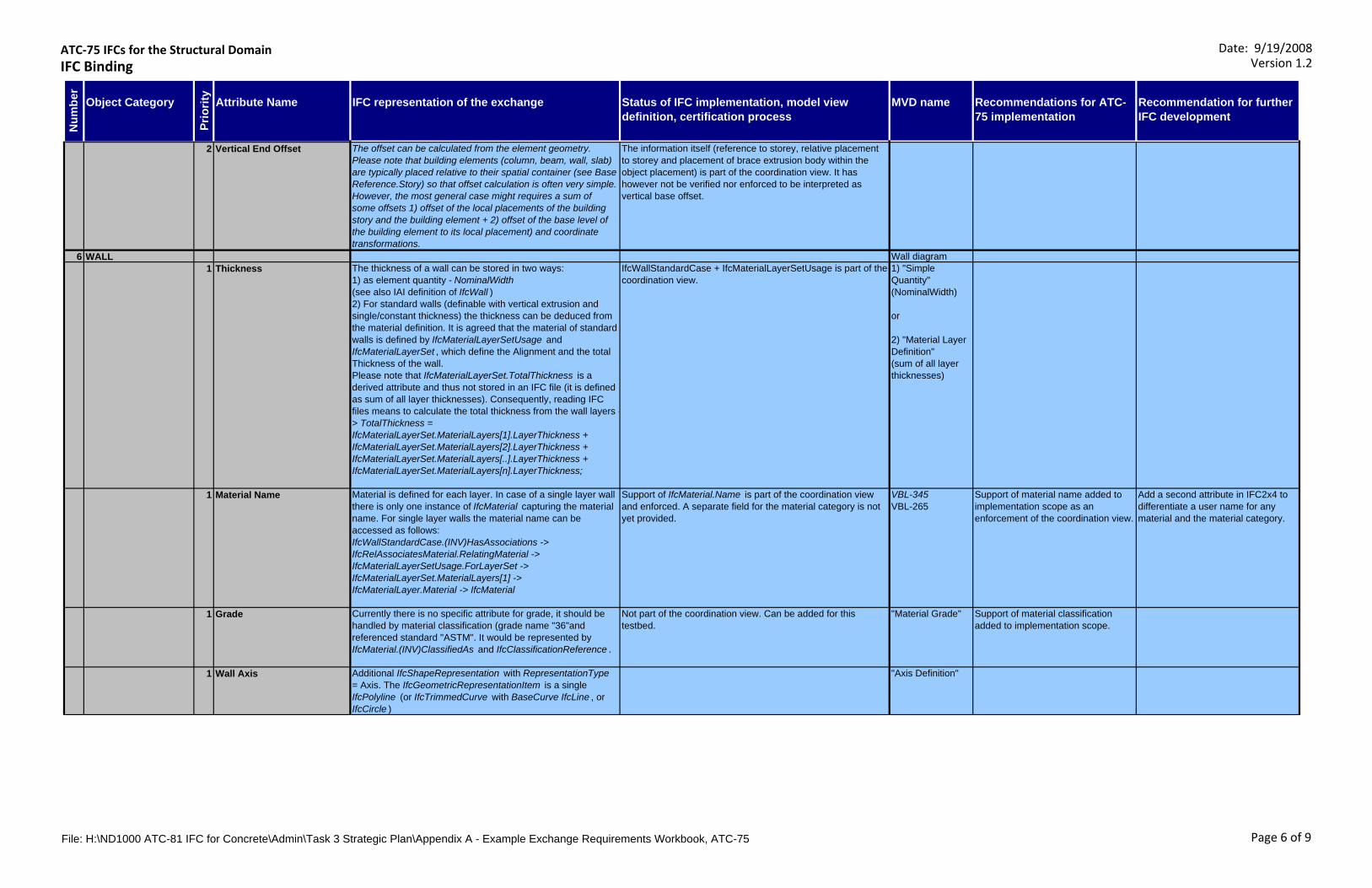
ATC‐75 IFCs for the Structural DomainIFC Binding
Date: 9/19/2008Version 1.2
Object Category Attribute Name IFC representation of the exchange Status of IFC implementation, model view definition, certification process
MVD name Recommendations for ATC-75 implementation
Recommendation for further IFC development
Num
ber
Prio
rity
2 Vertical End Offset The offset can be calculated from the element geometry. Please note that building elements (column, beam, wall, slab) are typically placed relative to their spatial container (see Base Reference.Story) so that offset calculation is often very simple. However, the most general case might requires a sum of some offsets 1) offset of the local placements of the building story and the building element + 2) offset of the base level of the building element to its local placement) and coordinate transformations.
The information itself (reference to storey, relative placement to storey and placement of brace extrusion body within the object placement) is part of the coordination view. It has however not be verified nor enforced to be interpreted as vertical base offset.
6 WALL Wall diagram1 Thickness The thickness of a wall can be stored in two ways:
1) as element quantity - NominalWidth (see also IAI definition of IfcWall ) 2) For standard walls (definable with vertical extrusion and single/constant thickness) the thickness can be deduced from the material definition. It is agreed that the material of standard walls is defined by IfcMaterialLayerSetUsage and IfcMaterialLayerSet , which define the Alignment and the total Thickness of the wall. Please note that IfcMaterialLayerSet.TotalThickness is a derived attribute and thus not stored in an IFC file (it is defined as sum of all layer thicknesses). Consequently, reading IFC files means to calculate the total thickness from the wall layers -> TotalThickness = IfcMaterialLayerSet.MaterialLayers[1].LayerThickness + IfcMaterialLayerSet.MaterialLayers[2].LayerThickness + IfcMaterialLayerSet.MaterialLayers[..].LayerThickness + IfcMaterialLayerSet.MaterialLayers[n].LayerThickness;
IfcWallStandardCase + IfcMaterialLayerSetUsage is part of the coordination view.
1) "Simple Quantity" (NominalWidth)
or
2) "Material Layer Definition" (sum of all layer thicknesses)
1 Material Name Material is defined for each layer. In case of a single layer wall there is only one instance of IfcMaterial capturing the material name. For single layer walls the material name can be accessed as follows: IfcWallStandardCase.(INV)HasAssociations -> IfcRelAssociatesMaterial.RelatingMaterial -> IfcMaterialLayerSetUsage.ForLayerSet ->IfcMaterialLayerSet.MaterialLayers[1] ->IfcMaterialLayer.Material -> IfcMaterial
Support of IfcMaterial.Name is part of the coordination view and enforced. A separate field for the material category is not yet provided.
VBL-345VBL-265
Support of material name added to implementation scope as an enforcement of the coordination view.
Add a second attribute in IFC2x4 to differentiate a user name for any material and the material category.
1 Grade Currently there is no specific attribute for grade, it should be handled by material classification (grade name "36"and referenced standard "ASTM". It would be represented by IfcMaterial.(INV)ClassifiedAs and IfcClassificationReference .
Not part of the coordination view. Can be added for this testbed.
"Material Grade" Support of material classification added to implementation scope.
1 Wall Axis Additional IfcShapeRepresentation with RepresentationType = Axis. The IfcGeometricRepresentationItem is a single IfcPolyline (or IfcTrimmedCurve with BaseCurve IfcLine , or IfcCircle )
"Axis Definition"
File: H:\ND1000 ATC-81 IFC for Concrete\Admin\Task 3 Strategic Plan\Appendix A - Example Exchange Requirements Workbook, ATC-75 Page 6 of 9
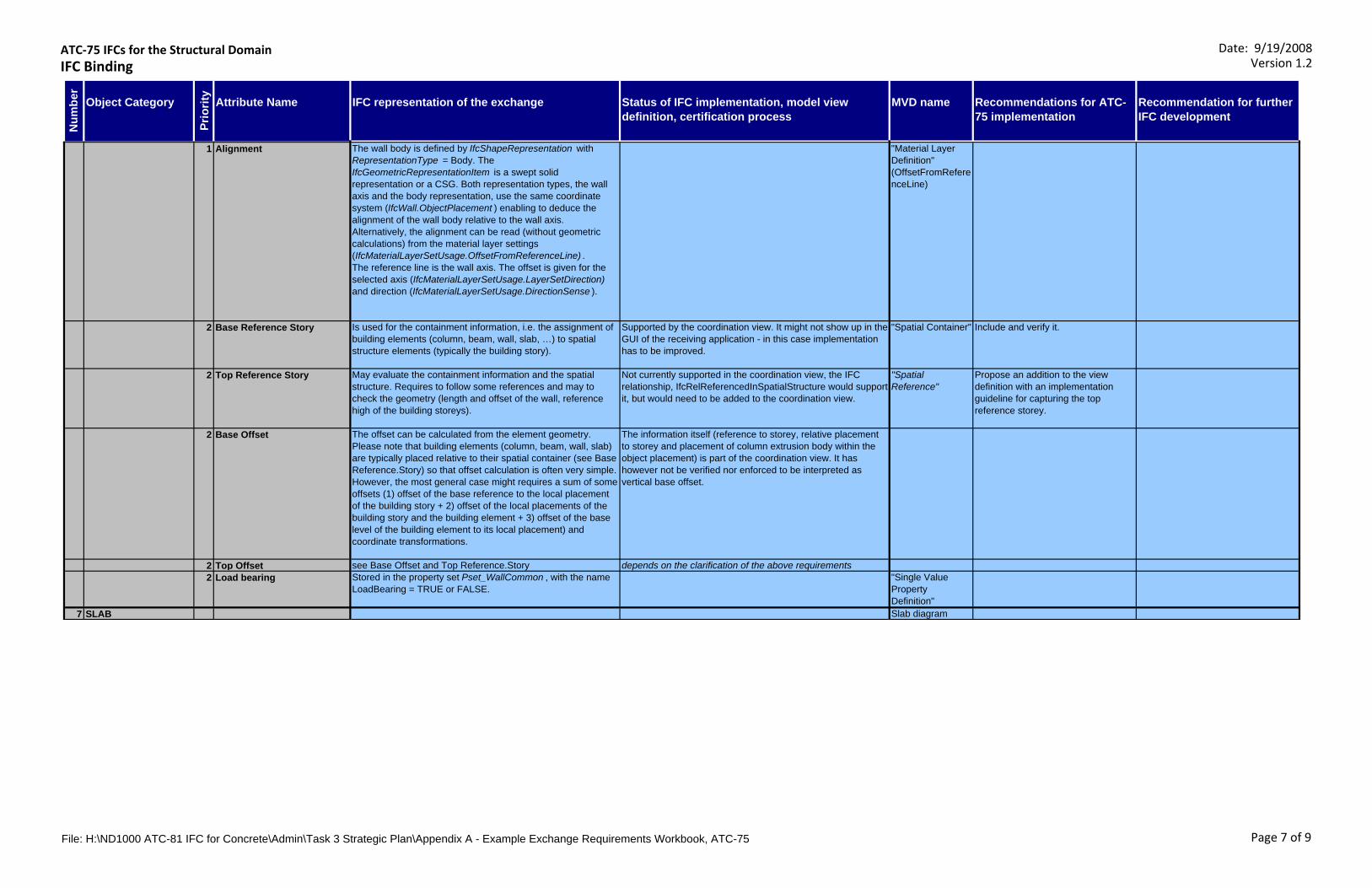
ATC‐75 IFCs for the Structural DomainIFC Binding
Date: 9/19/2008Version 1.2
Object Category Attribute Name IFC representation of the exchange Status of IFC implementation, model view definition, certification process
MVD name Recommendations for ATC-75 implementation
Recommendation for further IFC development
Num
ber
Prio
rity
1 Alignment The wall body is defined by IfcShapeRepresentation with RepresentationType = Body. The IfcGeometricRepresentationItem is a swept solid representation or a CSG. Both representation types, the wall axis and the body representation, use the same coordinate system (IfcWall.ObjectPlacement ) enabling to deduce the alignment of the wall body relative to the wall axis.Alternatively, the alignment can be read (without geometric calculations) from the material layer settings (IfcMaterialLayerSetUsage.OffsetFromReferenceLine) . The reference line is the wall axis. The offset is given for the selected axis (IfcMaterialLayerSetUsage.LayerSetDirection) and direction (IfcMaterialLayerSetUsage.DirectionSense ).
"Material Layer Definition" (OffsetFromReferenceLine)
2 Base Reference Story Is used for the containment information, i.e. the assignment of building elements (column, beam, wall, slab, …) to spatial structure elements (typically the building story).
Supported by the coordination view. It might not show up in the GUI of the receiving application - in this case implementation has to be improved.
"Spatial Container" Include and verify it.
2 Top Reference Story May evaluate the containment information and the spatial structure. Requires to follow some references and may to check the geometry (length and offset of the wall, reference high of the building storeys).
Not currently supported in the coordination view, the IFC relationship, IfcRelReferencedInSpatialStructure would support it, but would need to be added to the coordination view.
"Spatial Reference"
Propose an addition to the view definition with an implementation guideline for capturing the top reference storey.
2 Base Offset The offset can be calculated from the element geometry. Please note that building elements (column, beam, wall, slab) are typically placed relative to their spatial container (see Base Reference.Story) so that offset calculation is often very simple. However, the most general case might requires a sum of some offsets (1) offset of the base reference to the local placement of the building story + 2) offset of the local placements of the building story and the building element + 3) offset of the base level of the building element to its local placement) and coordinate transformations.
The information itself (reference to storey, relative placement to storey and placement of column extrusion body within the object placement) is part of the coordination view. It has however not be verified nor enforced to be interpreted as vertical base offset.
2 Top Offset see Base Offset and Top Reference.Story depends on the clarification of the above requirements2 Load bearing Stored in the property set Pset_WallCommon , with the name
LoadBearing = TRUE or FALSE."Single Value Property Definition"
7 SLAB Slab diagram
File: H:\ND1000 ATC-81 IFC for Concrete\Admin\Task 3 Strategic Plan\Appendix A - Example Exchange Requirements Workbook, ATC-75 Page 7 of 9
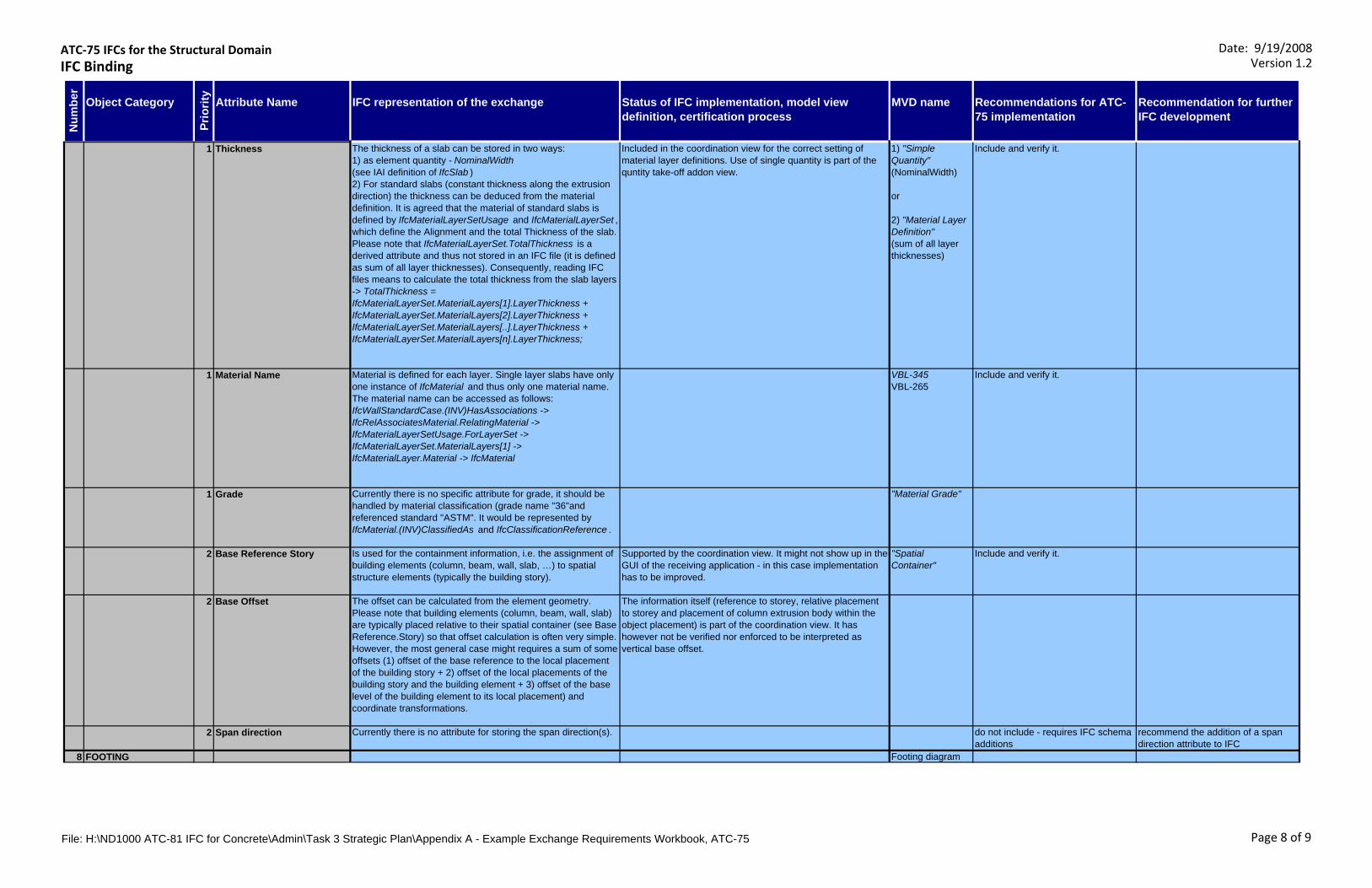
ATC‐75 IFCs for the Structural DomainIFC Binding
Date: 9/19/2008Version 1.2
Object Category Attribute Name IFC representation of the exchange Status of IFC implementation, model view definition, certification process
MVD name Recommendations for ATC-75 implementation
Recommendation for further IFC development
Num
ber
Prio
rity
1 Thickness The thickness of a slab can be stored in two ways:1) as element quantity - NominalWidth (see IAI definition of IfcSlab ) 2) For standard slabs (constant thickness along the extrusion direction) the thickness can be deduced from the material definition. It is agreed that the material of standard slabs is defined by IfcMaterialLayerSetUsage and IfcMaterialLayerSet , which define the Alignment and the total Thickness of the slab. Please note that IfcMaterialLayerSet.TotalThickness is a derived attribute and thus not stored in an IFC file (it is defined as sum of all layer thicknesses). Consequently, reading IFC files means to calculate the total thickness from the slab layers -> TotalThickness = IfcMaterialLayerSet.MaterialLayers[1].LayerThickness + IfcMaterialLayerSet.MaterialLayers[2].LayerThickness + IfcMaterialLayerSet.MaterialLayers[..].LayerThickness + IfcMaterialLayerSet.MaterialLayers[n].LayerThickness;
Included in the coordination view for the correct setting of material layer definitions. Use of single quantity is part of the quntity take-off addon view.
1) "Simple Quantity" (NominalWidth)
or
2) "Material Layer Definition" (sum of all layer thicknesses)
Include and verify it.
1 Material Name Material is defined for each layer. Single layer slabs have only one instance of IfcMaterial and thus only one material name. The material name can be accessed as follows: IfcWallStandardCase.(INV)HasAssociations -> IfcRelAssociatesMaterial.RelatingMaterial -> IfcMaterialLayerSetUsage.ForLayerSet ->IfcMaterialLayerSet.MaterialLayers[1] ->IfcMaterialLayer.Material -> IfcMaterial
VBL-345VBL-265
Include and verify it.
1 Grade Currently there is no specific attribute for grade, it should be handled by material classification (grade name "36"and referenced standard "ASTM". It would be represented by IfcMaterial.(INV)ClassifiedAs and IfcClassificationReference .
"Material Grade"
2 Base Reference Story Is used for the containment information, i.e. the assignment of building elements (column, beam, wall, slab, …) to spatial structure elements (typically the building story).
Supported by the coordination view. It might not show up in the GUI of the receiving application - in this case implementation has to be improved.
"Spatial Container"
Include and verify it.
2 Base Offset The offset can be calculated from the element geometry. Please note that building elements (column, beam, wall, slab) are typically placed relative to their spatial container (see Base Reference.Story) so that offset calculation is often very simple. However, the most general case might requires a sum of some offsets (1) offset of the base reference to the local placement of the building story + 2) offset of the local placements of the building story and the building element + 3) offset of the base level of the building element to its local placement) and coordinate transformations.
The information itself (reference to storey, relative placement to storey and placement of column extrusion body within the object placement) is part of the coordination view. It has however not be verified nor enforced to be interpreted as vertical base offset.
2 Span direction Currently there is no attribute for storing the span direction(s). do not include - requires IFC schema additions
recommend the addition of a span direction attribute to IFC
8 FOOTING Footing diagram
File: H:\ND1000 ATC-81 IFC for Concrete\Admin\Task 3 Strategic Plan\Appendix A - Example Exchange Requirements Workbook, ATC-75 Page 8 of 9

ATC‐75 IFCs for the Structural DomainIFC Binding
Date: 9/19/2008Version 1.2
Object Category Attribute Name IFC representation of the exchange Status of IFC implementation, model view definition, certification process
MVD name Recommendations for ATC-75 implementation
Recommendation for further IFC development
Num
ber
Prio
rity
1 Footing Type Defined by IfcFooting.PredefinedType ; following types are available: - FOOTING_BEAM- PAD_FOOTING- PILE_CAP- STRIP_FOOTING- USERDEFINED- NOTDEFINED
Included in the coordination view, but correct setting of the pile enumeration not enforced.
Check the current setting ot the pile type in IFC exchanges for benchmarking.
1 Material Name IfcMaterial.Name - it is currently the only string value applicable for material name. There is no distinction between a material name as general name and material category (steel, column, timber, etc.)
VBL-345VBL-265
Include and verify it.
1 Grade Currently there is no specific attribute for grade, it should be handled by material classification (grade name "36"and referenced standard "ASTM". It would be represented by IfcMaterial.(INV)ClassifiedAs and IfcClassificationReference .
"Material Grade"
2 Top Reference Story Is used for the containment information, i.e. the assignment of building elements (column, beam, wall, slab, …) to spatial structure elements (typically the building story). Note: it is the reference storey (the term "top" is not preserved in the exchange)
Supported by the coordination view. It might not show up in the GUI of the receiving application - in this case implementation has to be improved.
"Spatial Container" Include and verify it.
2 Bottom Elevation Equal to the extrusion lenght parameter of the footing9 PILE Pile diagram
1 Pile Type Defined by IfcPile.PredefinedType;following types are available:- COHESION- FRICTION- SUPPORT- USERDEFINED- NOTDEFINED
Included in the coordination view, but correct setting of the pile enumeration not enforced.
Check the current setting ot the pile type in IFC exchanges for benchmarking.
1 Material Name IfcMaterial.Name - it is currently the only string value applicable for material name. There is no distinction between a material name as general name and material category (steel, column, timber, etc.)
VBL-345VBL-265
Include and verify it.
1 Grade Currently there is no specific attribute for grade, it should be handled by material classification (grade name "36"and referenced standard "ASTM". It would be represented by IfcMaterial.(INV)ClassifiedAs and IfcClassificationReference .
"Material Grade"
2 Top Reference.Story Is used for the containment information, i.e. the assignment of building elements (column, beam, wall, slab, …) to spatial structure elements (typically the building story). Note: it is the reference storey (the term "top" is not preserved in the exchange)
Supported by the coordination view. It might not show up in the GUI of the receiving application - in this case implementation has to be improved.
"Spatial Container" Include and verify it.
2 Bottom Elevation
File: H:\ND1000 ATC-81 IFC for Concrete\Admin\Task 3 Strategic Plan\Appendix A - Example Exchange Requirements Workbook, ATC-75 Page 9 of 9
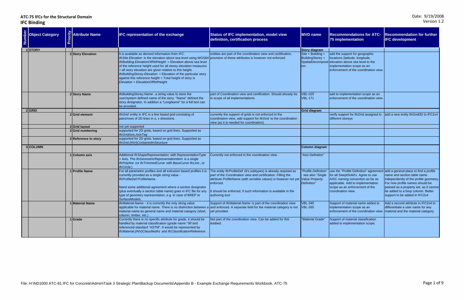
ATC‐75 IFCs for the Structural DomainIFC Binding
Date: 9/19/2008Version 1.2
Object Category Attribute Name IFC representation of the exchange Status of IFC implementation, model view definition, certification process
MVD name Recommendations for ATC-75 implementation
Recommendation for further IFC development
1 STORY Story diagram2 Story Elevation It is available as derived information from IFC.
IfcSite.Elevation is the elevation about sea level using WGS84IfcBuilding.ElevationOfRefHeight = Elevation above sea level of the reference height used for all storey elevation measures = all story elevation are given relative to this height.IfcBuildingStorey.Elevation = Elevation of the particular story against this reference height = Total height of story is Elevation + ElevationOfRefHeight
entities are part of the coordination view and certification, provision of these attributes is however not enforced.
Site + Building + BuildingStorey +SpatialDecomposition
add the support for geographic locations (latitude, longitude, elevation above sea level to the implementation scope as an enforcement of the coordination view.
2 Story Name IfcBuildingStorey.Name , a string value to store the user/system defined name of the story. "Name" defined the story designator, In addition a "LongName" for a full text can be provided.
part of Coordination view and certification. Should already be in scope of all implementations.
VBL-025VBL-171
add to implementation scope as an enforcement of the coordination view.
2 GRID Grid diagram2 Grid element IfcGrid entity in IFC is a line based grid consisting of
pairs/rows of 2D lines in u, v directions.currently the support of grids is not enforced in the coordination view, add support for IfcGrid to the coordination view (as it is needed for coordination).
verify support for IfcGrid assigned to different storeys
add a new entity IfcGrid3D to IFC2x4
2 Grid layout not yet supported2 Grid numbering supported for 2D grids, based on grid lines. Supported as
IfcGridAxis.AxisTag2 Reference to story supported for 2D grids, based on grid lines. Supported as
IfcGrid.(INV)ContainedInStructure 3 COLUMN Column diagram
1 Column axis Additional IfcShapeRepresentation with RepresentationType = Axis. The IfcGeometricRepresentationItem is a single IfcPolyline (or IfcTrimmedCurve with BaseCurve IfcLine , or IfcCircle )
Currently not enforced in the coordination view. "Axis Definition"
1 Profile Name For all parametric profiles and all extrusion based profiles it is currently provided as a single string value - IfcProfileDef.ProfileName.
Need some additional agreement where a section designator (plus eventually a section table name) goes in IFC file for any type of geometry representation, e.g. in case of BREP or SurfaceModels.
The entity IfcProfileDef (it's subtypes) is already required as part of the Coordination view and certification. Filling the attribute ProfileName (with sensible values) is however not yet enforced.
It should be enforced, if such information is available in the authoring tool.
"Profile Definition" - see also "Single Value Property Definition"
use the "Profile Definition" agreement for all SweptSolid's. Agree to use AISC naming convention as far as applicable. Add to implementation scope as an enforcement of the coordination view.
add a general place to find a profile name and section table name independently of the profile geometry. For now profile names should be passed as a property set, as it cannot be added to a brep column. Better support to be added in IFC2x4
1 Material Name IfcMaterial.Name - it is currently the only string value applicable for material name. There is no distinction between a material name as general name and material category (steel, column, timber, etc.)
Support of IfcMaterial.Name is part of the coordination view and enforced. A separate field for the material category is not yet provided.
VBL-345VBL-265
Support of material name added to implementation scope as an enforcement of the coordination view.
Add a second attribute in IFC2x4 to differentiate a user name for any material and the material category.
1 Grade Currently there is no specific attribute for grade, it should be handled by material classification (grade name "36"and referenced standard "ASTM". It would be represented by IfcMaterial.(INV)ClassifiedAs and IfcClassificationReference .
Not part of the coordination view. Can be added for this testbed.
"Material Grade" Support of material classification added to implementation scope.
Num
ber
Prio
rity
File: H:\ND1000 ATC-81 IFC for Concrete\Admin\Task 3 Strategic Plan\Backup Documents\Appendix B - Example Exchange Requirements Workbook, ATC-75 Page 1 of 9
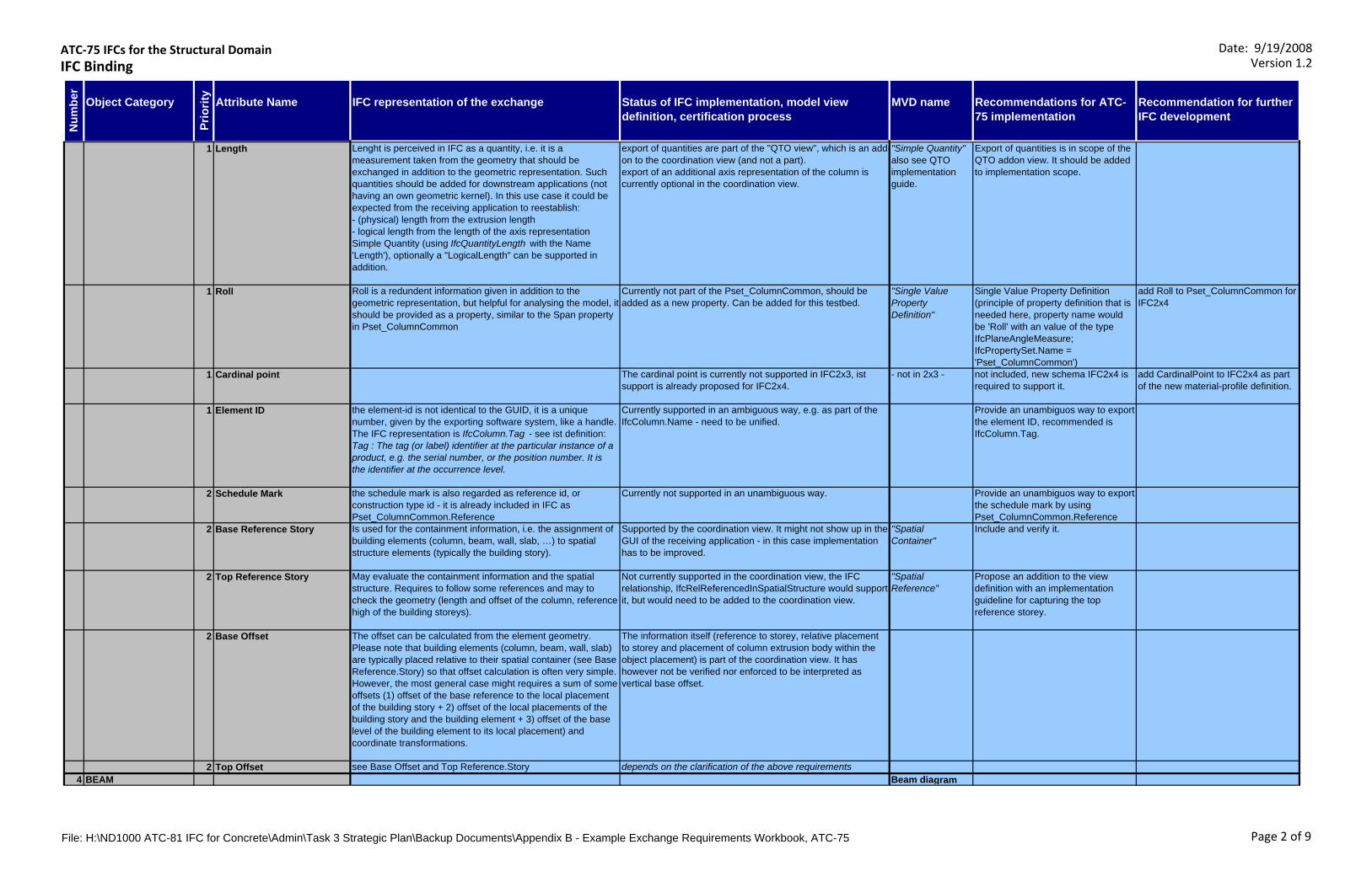
ATC‐75 IFCs for the Structural DomainIFC Binding
Date: 9/19/2008Version 1.2
Object Category Attribute Name IFC representation of the exchange Status of IFC implementation, model view definition, certification process
MVD name Recommendations for ATC-75 implementation
Recommendation for further IFC development
Num
ber
Prio
rity
1 Length Lenght is perceived in IFC as a quantity, i.e. it is a measurement taken from the geometry that should be exchanged in addition to the geometric representation. Such quantities should be added for downstream applications (not having an own geometric kernel). In this use case it could be expected from the receiving application to reestablish:- (physical) length from the extrusion length- logical length from the length of the axis representationSimple Quantity (using IfcQuantityLength with the Name 'Length'), optionally a "LogicalLength" can be supported in addition.
export of quantities are part of the "QTO view", which is an add-on to the coordination view (and not a part).export of an additional axis representation of the column is currently optional in the coordination view.
"Simple Quantity" also see QTO implementation guide.
Export of quantities is in scope of the QTO addon view. It should be added to implementation scope.
1 Roll Roll is a redundent information given in addition to the geometric representation, but helpful for analysing the model, it should be provided as a property, similar to the Span property in Pset_ColumnCommon
Currently not part of the Pset_ColumnCommon, should be added as a new property. Can be added for this testbed.
"Single Value Property Definition"
Single Value Property Definition (principle of property definition that is needed here, property name would be 'Roll' with an value of the type IfcPlaneAngleMeasure;IfcPropertySet.Name = 'Pset_ColumnCommon')
add Roll to Pset_ColumnCommon for IFC2x4
1 Cardinal point The cardinal point is currently not supported in IFC2x3, ist support is already proposed for IFC2x4.
- not in 2x3 - not included, new schema IFC2x4 is required to support it.
add CardinalPoint to IFC2x4 as part of the new material-profile definition.
1 Element ID the element-id is not identical to the GUID, it is a unique number, given by the exporting software system, like a handle. The IFC representation is IfcColumn.Tag - see ist definition: Tag : The tag (or label) identifier at the particular instance of a product, e.g. the serial number, or the position number. It is the identifier at the occurrence level.
Currently supported in an ambiguous way, e.g. as part of the IfcColumn.Name - need to be unified.
Provide an unambiguos way to export the element ID, recommended is IfcColumn.Tag.
2 Schedule Mark the schedule mark is also regarded as reference id, or construction type id - it is already included in IFC as Pset_ColumnCommon.Reference
Currently not supported in an unambiguous way. Provide an unambiguos way to export the schedule mark by using Pset_ColumnCommon.Reference
2 Base Reference Story Is used for the containment information, i.e. the assignment of building elements (column, beam, wall, slab, …) to spatial structure elements (typically the building story).
Supported by the coordination view. It might not show up in the GUI of the receiving application - in this case implementation has to be improved.
"Spatial Container"
Include and verify it.
2 Top Reference Story May evaluate the containment information and the spatial structure. Requires to follow some references and may to check the geometry (length and offset of the column, reference high of the building storeys).
Not currently supported in the coordination view, the IFC relationship, IfcRelReferencedInSpatialStructure would support it, but would need to be added to the coordination view.
"Spatial Reference"
Propose an addition to the view definition with an implementation guideline for capturing the top reference storey.
2 Base Offset The offset can be calculated from the element geometry. Please note that building elements (column, beam, wall, slab) are typically placed relative to their spatial container (see Base Reference.Story) so that offset calculation is often very simple. However, the most general case might requires a sum of some offsets (1) offset of the base reference to the local placement of the building story + 2) offset of the local placements of the building story and the building element + 3) offset of the base level of the building element to its local placement) and coordinate transformations.
The information itself (reference to storey, relative placement to storey and placement of column extrusion body within the object placement) is part of the coordination view. It has however not be verified nor enforced to be interpreted as vertical base offset.
2 Top Offset see Base Offset and Top Reference.Story depends on the clarification of the above requirements4 BEAM Beam diagram
File: H:\ND1000 ATC-81 IFC for Concrete\Admin\Task 3 Strategic Plan\Backup Documents\Appendix B - Example Exchange Requirements Workbook, ATC-75 Page 2 of 9
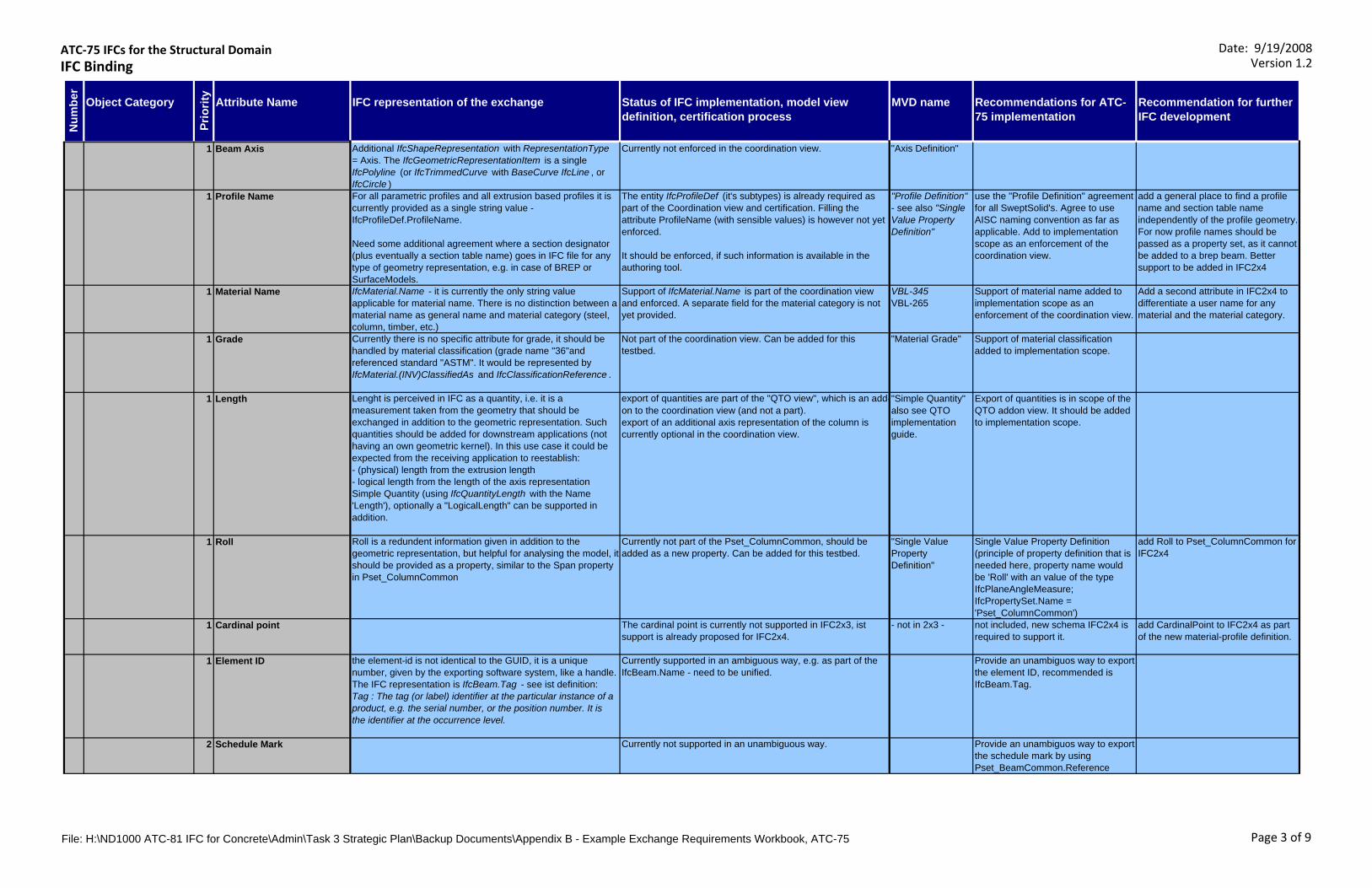
ATC‐75 IFCs for the Structural DomainIFC Binding
Date: 9/19/2008Version 1.2
Object Category Attribute Name IFC representation of the exchange Status of IFC implementation, model view definition, certification process
MVD name Recommendations for ATC-75 implementation
Recommendation for further IFC development
Num
ber
Prio
rity
1 Beam Axis Additional IfcShapeRepresentation with RepresentationType = Axis. The IfcGeometricRepresentationItem is a single IfcPolyline (or IfcTrimmedCurve with BaseCurve IfcLine , or IfcCircle )
Currently not enforced in the coordination view. "Axis Definition"
1 Profile Name For all parametric profiles and all extrusion based profiles it is currently provided as a single string value - IfcProfileDef.ProfileName.
Need some additional agreement where a section designator (plus eventually a section table name) goes in IFC file for any type of geometry representation, e.g. in case of BREP or SurfaceModels.
The entity IfcProfileDef (it's subtypes) is already required as part of the Coordination view and certification. Filling the attribute ProfileName (with sensible values) is however not yet enforced.
It should be enforced, if such information is available in the authoring tool.
"Profile Definition" - see also "Single Value Property Definition"
use the "Profile Definition" agreement for all SweptSolid's. Agree to use AISC naming convention as far as applicable. Add to implementation scope as an enforcement of the coordination view.
add a general place to find a profile name and section table name independently of the profile geometry. For now profile names should be passed as a property set, as it cannot be added to a brep beam. Better support to be added in IFC2x4
1 Material Name IfcMaterial.Name - it is currently the only string value applicable for material name. There is no distinction between a material name as general name and material category (steel, column, timber, etc.)
Support of IfcMaterial.Name is part of the coordination view and enforced. A separate field for the material category is not yet provided.
VBL-345VBL-265
Support of material name added to implementation scope as an enforcement of the coordination view.
Add a second attribute in IFC2x4 to differentiate a user name for any material and the material category.
1 Grade Currently there is no specific attribute for grade, it should be handled by material classification (grade name "36"and referenced standard "ASTM". It would be represented by IfcMaterial.(INV)ClassifiedAs and IfcClassificationReference .
Not part of the coordination view. Can be added for this testbed.
"Material Grade" Support of material classification added to implementation scope.
1 Length Lenght is perceived in IFC as a quantity, i.e. it is a measurement taken from the geometry that should be exchanged in addition to the geometric representation. Such quantities should be added for downstream applications (not having an own geometric kernel). In this use case it could be expected from the receiving application to reestablish:- (physical) length from the extrusion length- logical length from the length of the axis representationSimple Quantity (using IfcQuantityLength with the Name 'Length'), optionally a "LogicalLength" can be supported in addition.
export of quantities are part of the "QTO view", which is an add-on to the coordination view (and not a part).export of an additional axis representation of the column is currently optional in the coordination view.
"Simple Quantity" also see QTO implementation guide.
Export of quantities is in scope of the QTO addon view. It should be added to implementation scope.
1 Roll Roll is a redundent information given in addition to the geometric representation, but helpful for analysing the model, it should be provided as a property, similar to the Span property in Pset_ColumnCommon
Currently not part of the Pset_ColumnCommon, should be added as a new property. Can be added for this testbed.
"Single Value Property Definition"
Single Value Property Definition (principle of property definition that is needed here, property name would be 'Roll' with an value of the type IfcPlaneAngleMeasure;IfcPropertySet.Name = 'Pset_ColumnCommon')
add Roll to Pset_ColumnCommon for IFC2x4
1 Cardinal point The cardinal point is currently not supported in IFC2x3, ist support is already proposed for IFC2x4.
- not in 2x3 - not included, new schema IFC2x4 is required to support it.
add CardinalPoint to IFC2x4 as part of the new material-profile definition.
1 Element ID the element-id is not identical to the GUID, it is a unique number, given by the exporting software system, like a handle. The IFC representation is IfcBeam.Tag - see ist definition: Tag : The tag (or label) identifier at the particular instance of a product, e.g. the serial number, or the position number. It is the identifier at the occurrence level.
Currently supported in an ambiguous way, e.g. as part of the IfcBeam.Name - need to be unified.
Provide an unambiguos way to export the element ID, recommended is IfcBeam.Tag.
2 Schedule Mark Currently not supported in an unambiguous way. Provide an unambiguos way to export the schedule mark by using Pset_BeamCommon.Reference
File: H:\ND1000 ATC-81 IFC for Concrete\Admin\Task 3 Strategic Plan\Backup Documents\Appendix B - Example Exchange Requirements Workbook, ATC-75 Page 3 of 9

ATC‐75 IFCs for the Structural DomainIFC Binding
Date: 9/19/2008Version 1.2
Object Category Attribute Name IFC representation of the exchange Status of IFC implementation, model view definition, certification process
MVD name Recommendations for ATC-75 implementation
Recommendation for further IFC development
Num
ber
Prio
rity
2 Base Reference Story Is used for the containment information, i.e. the assignment of building elements (column, beam, wall, slab, …) to spatial structure elements (typically the building story).
Supported by the coordination view. It might not show up in the GUI of the receiving application - in this case implementation has to be improved.
Propose an addition to the view definition with an implementation guideline for capturing the top reference storey.
2 Vertical Start Offset The offset can be calculated from the element geometry. Please note that building elements (column, beam, wall, slab) are typically placed relative to their spatial container (see Base Reference.Story) so that offset calculation is often very simple. However, the most general case might requires a sum of some offsets 1) offset of the local placements of the building story and the building element + 2) offset of the base level of the building element to its local placement) and coordinate transformations.
The information itself (reference to storey, relative placement to storey and placement of column extrusion body within the object placement) is part of the coordination view. It has however not be verified nor enforced to be interpreted as vertical base offset.
Add an implematation guide on how to re-generate the offset exported as part of the local placement and geometric representation.
2 Vertical End Offset The offset can be calculated from the element geometry. Please note that building elements (column, beam, wall, slab) are typically placed relative to their spatial container (see Base Reference.Story) so that offset calculation is often very simple. However, the most general case might requires a sum of some offsets 1) offset of the local placements of the building story and the building element + 2) offset of the base level of the building element to its local placement) and coordinate transformations.
The information itself (reference to storey, relative placement to storey and placement of column extrusion body within the object placement) is part of the coordination view. It has however not be verified nor enforced to be interpreted as vertical base offset.
Add an implematation guide on how to re-generate the offset exported as part of the local placement and geometric representation.
5 BRACE Brace is not an individual entity in IFC. A brace is represented as a IfcMemberType with PredefinedType=.BRACE. If no types are exchanged, each individual occurrence shall be an IfcMember with ObjectType='Brace'.
Labelling members as braces is currently not enforced in the coordination view. It should be enforced, if such information is available in the authoring tool.
Brace diagram
1 Brace Axis Additional IfcShapeRepresentation with RepresentationType = Axis. The IfcGeometricRepresentationItem is a single IfcPolyline (or IfcTrimmedCurve with BaseCurve IfcLine , or IfcCircle )
Currently not enforced in the coordination view. "Axis Definition"
1 Profile Name For all parametric profiles and all extrusion based profiles it is currently provided as a single string value - IfcProfileDef.ProfileName.
Need some additional agreement where a section designator (plus eventually a section table name) goes in IFC file for any type of geometry representation, e.g. in case of BREP or SurfaceModels.
The entity IfcProfileDef (it's subtypes) is already required as part of the Coordination view and certification. Filling the attribute ProfileName (with sensible values) is however not yet enforced.
It should be enforced, if such information is available in the authoring tool.
"Profile Definition" - see also "Single Value Property Definition"
use the "Profile Definition" agreement for all SweptSolid's. Agree to use AISC naming convention as far as applicable. Add to implementation scope as an enforcement of the coordination view.
add a general place to find a profile name and section table name independently of the profile geometry. For now profile names should be passed as a property set, as it cannot be added to a brep brace. Better support to be added in IFC2x4
1 Material Name IfcMaterial.Name - it is currently the only string value applicable for material name. There is no distinction between a material name as general name and material category (steel, column, timber, etc.)
Support of IfcMaterial.Name is part of the coordination view and enforced. A separate field for the material category is not yet provided.
VBL-345VBL-265
Support of material name added to implementation scope as an enforcement of the coordination view.
Add a second attribute in IFC2x4 to differentiate a user name for any material and the material category.
1 Grade Currently there is no specific attribute for grade, it should be handled by material classification (grade name "36"and referenced standard "ASTM". It would be represented by IfcMaterial.(INV)ClassifiedAs and IfcClassificationReference .
Not part of the coordination view. Can be added for this testbed.
"Material Grade" Support of material classification added to implementation scope.
File: H:\ND1000 ATC-81 IFC for Concrete\Admin\Task 3 Strategic Plan\Backup Documents\Appendix B - Example Exchange Requirements Workbook, ATC-75 Page 4 of 9
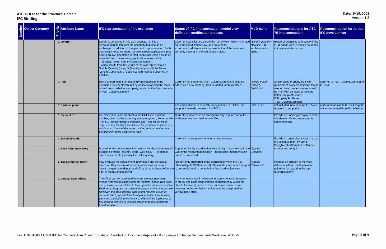
ATC‐75 IFCs for the Structural DomainIFC Binding
Date: 9/19/2008Version 1.2
Object Category Attribute Name IFC representation of the exchange Status of IFC implementation, model view definition, certification process
MVD name Recommendations for ATC-75 implementation
Recommendation for further IFC development
Num
ber
Prio
rity
1 Length Lenght is perceived in IFC as a quantity, i.e. it is a measurement taken from the geometry that should be exchanged in addition to the geometric representation. Such quantities should be added for downstream applications (not having an own geometric kernel). In this use case it could be expected from the receiving application to reestablish:- (physical) length from the extrusion length- logical length from the length of the axis representationSimple Quantity (using IfcQuantityLength with the Name 'Length'), optionally a "LogicalLength" can be supported in addition.
export of quantities are part of the "QTO view", which is an add-on to the coordination view (and not a part).export of an additional axis representation of the column is currently optional in the coordination view.
"Simple Quantity" also see QTO implementation guide.
Export of quantities is in scope of the QTO addon view. It should be added to implementation scope.
1 Roll Roll is a redundent information given in addition to the geometric representation, but helpful for analysing the model, it should be provided as a property, similar to the Span property in Pset_ColumnCommon
Currently not part of the Pset_ColumnCommon, should be added as a new property. Can be added for this testbed.
"Single Value Property Definition"
Single Value Property Definition (principle of property definition that is needed here, property name would be 'Roll' with an value of the type IfcPlaneAngleMeasure;IfcPropertySet.Name = 'Pset_ColumnCommon')
add Roll to Pset_ColumnCommon for IFC2x4
1 Cardinal point The cardinal point is currently not supported in IFC2x3, ist support is already proposed for IFC2x4.
- not in 2x3 - not included, new schema IFC2x4 is required to support it.
add CardinalPoint to IFC2x4 as part of the new material-profile definition.
1 Element ID the element-id is not identical to the GUID, it is a unique number, given by the exporting software system, like a handle. The IFC representation is IfcBeam.Tag - see ist definition: Tag : The tag (or label) identifier at the particular instance of a product, e.g. the serial number, or the position number. It is the identifier at the occurrence level.
Currently supported in an ambiguous way, e.g. as part of the IfcMember.Name - need to be unified.
Provide an unambiguos way to export the element ID, recommended is IfcMember.Tag.
2 Schedule Mark Currently not supported in an unambiguous way. Provide an unambiguos way to export the schedule mark by using Pset_MemberCommon.Reference
2 Base Reference Story Is used for the containment information, i.e. the assignment of building elements (column, beam, wall, slab, …) to spatial structure elements (typically the building story).
Supported by the coordination view. It might not show up in the GUI of the receiving application - in this case implementation has to be improved.
"Spatial Container"
Include and verify it.
2 Top Reference Story May evaluate the containment information and the spatial structure. Requires to follow some references and may to check the geometry (length and offset of the column, reference high of the building storeys).
Not currently supported in the coordination view, the IFC relationship, IfcRelReferencedInSpatialStructure would support it, but would need to be added to the coordination view.
"Spatial Reference"
Propose an addition to the view definition with an implementation guideline for capturing the top reference storey.
2 Vertical Start Offset The offset can be calculated from the element geometry. Please note that building elements (column, beam, wall, slab) are typically placed relative to their spatial container (see Base Reference.Story) so that offset calculation is often very simple. However, the most general case might requires a sum of some offsets 1) offset of the local placements of the building story and the building element + 2) offset of the base level of the building element to its local placement) and coordinate transformations.
The information itself (reference to storey, relative placement to storey and placement of brace extrusion body within the object placement) is part of the coordination view. It has however not be verified nor enforced to be interpreted as vertical base offset.
File: H:\ND1000 ATC-81 IFC for Concrete\Admin\Task 3 Strategic Plan\Backup Documents\Appendix B - Example Exchange Requirements Workbook, ATC-75 Page 5 of 9
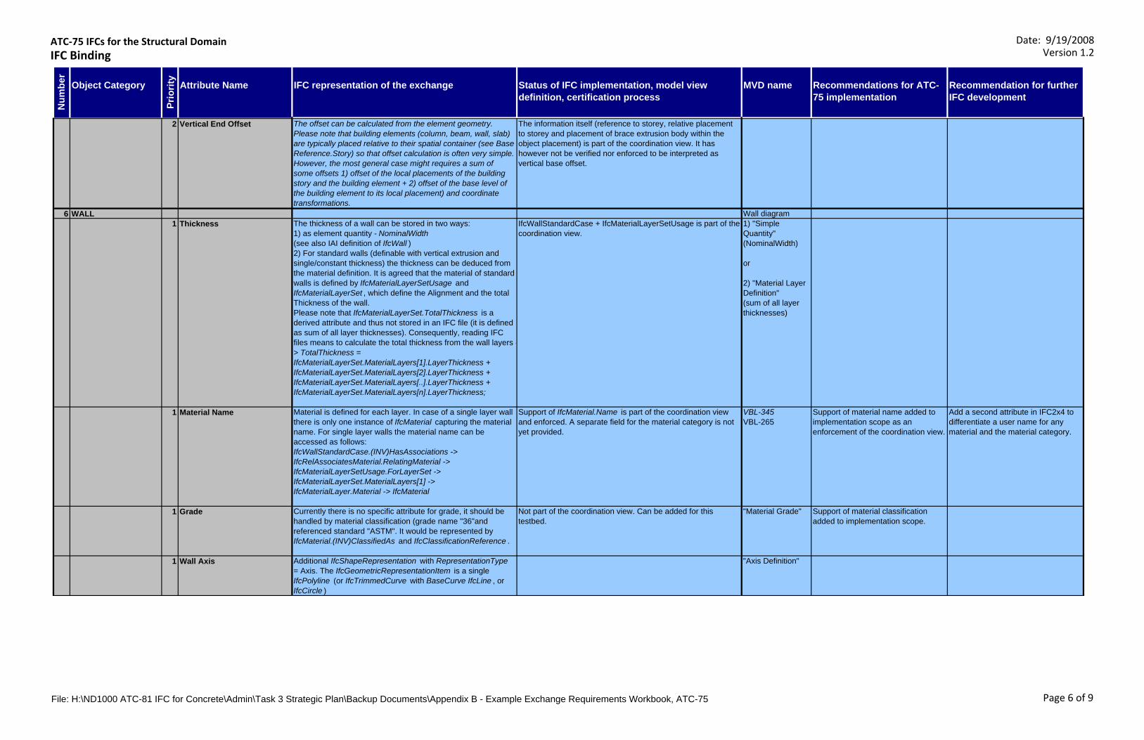
ATC‐75 IFCs for the Structural DomainIFC Binding
Date: 9/19/2008Version 1.2
Object Category Attribute Name IFC representation of the exchange Status of IFC implementation, model view definition, certification process
MVD name Recommendations for ATC-75 implementation
Recommendation for further IFC development
Num
ber
Prio
rity
2 Vertical End Offset The offset can be calculated from the element geometry. Please note that building elements (column, beam, wall, slab) are typically placed relative to their spatial container (see Base Reference.Story) so that offset calculation is often very simple. However, the most general case might requires a sum of some offsets 1) offset of the local placements of the building story and the building element + 2) offset of the base level of the building element to its local placement) and coordinate transformations.
The information itself (reference to storey, relative placement to storey and placement of brace extrusion body within the object placement) is part of the coordination view. It has however not be verified nor enforced to be interpreted as vertical base offset.
6 WALL Wall diagram1 Thickness The thickness of a wall can be stored in two ways:
1) as element quantity - NominalWidth (see also IAI definition of IfcWall ) 2) For standard walls (definable with vertical extrusion and single/constant thickness) the thickness can be deduced from the material definition. It is agreed that the material of standard walls is defined by IfcMaterialLayerSetUsage and IfcMaterialLayerSet , which define the Alignment and the total Thickness of the wall. Please note that IfcMaterialLayerSet.TotalThickness is a derived attribute and thus not stored in an IFC file (it is defined as sum of all layer thicknesses). Consequently, reading IFC files means to calculate the total thickness from the wall layers -> TotalThickness = IfcMaterialLayerSet.MaterialLayers[1].LayerThickness + IfcMaterialLayerSet.MaterialLayers[2].LayerThickness + IfcMaterialLayerSet.MaterialLayers[..].LayerThickness + IfcMaterialLayerSet.MaterialLayers[n].LayerThickness;
IfcWallStandardCase + IfcMaterialLayerSetUsage is part of the coordination view.
1) "Simple Quantity" (NominalWidth)
or
2) "Material Layer Definition" (sum of all layer thicknesses)
1 Material Name Material is defined for each layer. In case of a single layer wall there is only one instance of IfcMaterial capturing the material name. For single layer walls the material name can be accessed as follows: IfcWallStandardCase.(INV)HasAssociations -> IfcRelAssociatesMaterial.RelatingMaterial -> IfcMaterialLayerSetUsage.ForLayerSet ->IfcMaterialLayerSet.MaterialLayers[1] ->IfcMaterialLayer.Material -> IfcMaterial
Support of IfcMaterial.Name is part of the coordination view and enforced. A separate field for the material category is not yet provided.
VBL-345VBL-265
Support of material name added to implementation scope as an enforcement of the coordination view.
Add a second attribute in IFC2x4 to differentiate a user name for any material and the material category.
1 Grade Currently there is no specific attribute for grade, it should be handled by material classification (grade name "36"and referenced standard "ASTM". It would be represented by IfcMaterial.(INV)ClassifiedAs and IfcClassificationReference .
Not part of the coordination view. Can be added for this testbed.
"Material Grade" Support of material classification added to implementation scope.
1 Wall Axis Additional IfcShapeRepresentation with RepresentationType = Axis. The IfcGeometricRepresentationItem is a single IfcPolyline (or IfcTrimmedCurve with BaseCurve IfcLine , or IfcCircle )
"Axis Definition"
File: H:\ND1000 ATC-81 IFC for Concrete\Admin\Task 3 Strategic Plan\Backup Documents\Appendix B - Example Exchange Requirements Workbook, ATC-75 Page 6 of 9

ATC‐75 IFCs for the Structural DomainIFC Binding
Date: 9/19/2008Version 1.2
Object Category Attribute Name IFC representation of the exchange Status of IFC implementation, model view definition, certification process
MVD name Recommendations for ATC-75 implementation
Recommendation for further IFC development
Num
ber
Prio
rity
1 Alignment The wall body is defined by IfcShapeRepresentation with RepresentationType = Body. The IfcGeometricRepresentationItem is a swept solid representation or a CSG. Both representation types, the wall axis and the body representation, use the same coordinate system (IfcWall.ObjectPlacement ) enabling to deduce the alignment of the wall body relative to the wall axis.Alternatively, the alignment can be read (without geometric calculations) from the material layer settings (IfcMaterialLayerSetUsage.OffsetFromReferenceLine) . The reference line is the wall axis. The offset is given for the selected axis (IfcMaterialLayerSetUsage.LayerSetDirection) and direction (IfcMaterialLayerSetUsage.DirectionSense ).
"Material Layer Definition" (OffsetFromReferenceLine)
2 Base Reference Story Is used for the containment information, i.e. the assignment of building elements (column, beam, wall, slab, …) to spatial structure elements (typically the building story).
Supported by the coordination view. It might not show up in the GUI of the receiving application - in this case implementation has to be improved.
"Spatial Container" Include and verify it.
2 Top Reference Story May evaluate the containment information and the spatial structure. Requires to follow some references and may to check the geometry (length and offset of the wall, reference high of the building storeys).
Not currently supported in the coordination view, the IFC relationship, IfcRelReferencedInSpatialStructure would support it, but would need to be added to the coordination view.
"Spatial Reference"
Propose an addition to the view definition with an implementation guideline for capturing the top reference storey.
2 Base Offset The offset can be calculated from the element geometry. Please note that building elements (column, beam, wall, slab) are typically placed relative to their spatial container (see Base Reference.Story) so that offset calculation is often very simple. However, the most general case might requires a sum of some offsets (1) offset of the base reference to the local placement of the building story + 2) offset of the local placements of the building story and the building element + 3) offset of the base level of the building element to its local placement) and coordinate transformations.
The information itself (reference to storey, relative placement to storey and placement of column extrusion body within the object placement) is part of the coordination view. It has however not be verified nor enforced to be interpreted as vertical base offset.
2 Top Offset see Base Offset and Top Reference.Story depends on the clarification of the above requirements2 Load bearing Stored in the property set Pset_WallCommon , with the name
LoadBearing = TRUE or FALSE."Single Value Property Definition"
7 SLAB Slab diagram
File: H:\ND1000 ATC-81 IFC for Concrete\Admin\Task 3 Strategic Plan\Backup Documents\Appendix B - Example Exchange Requirements Workbook, ATC-75 Page 7 of 9
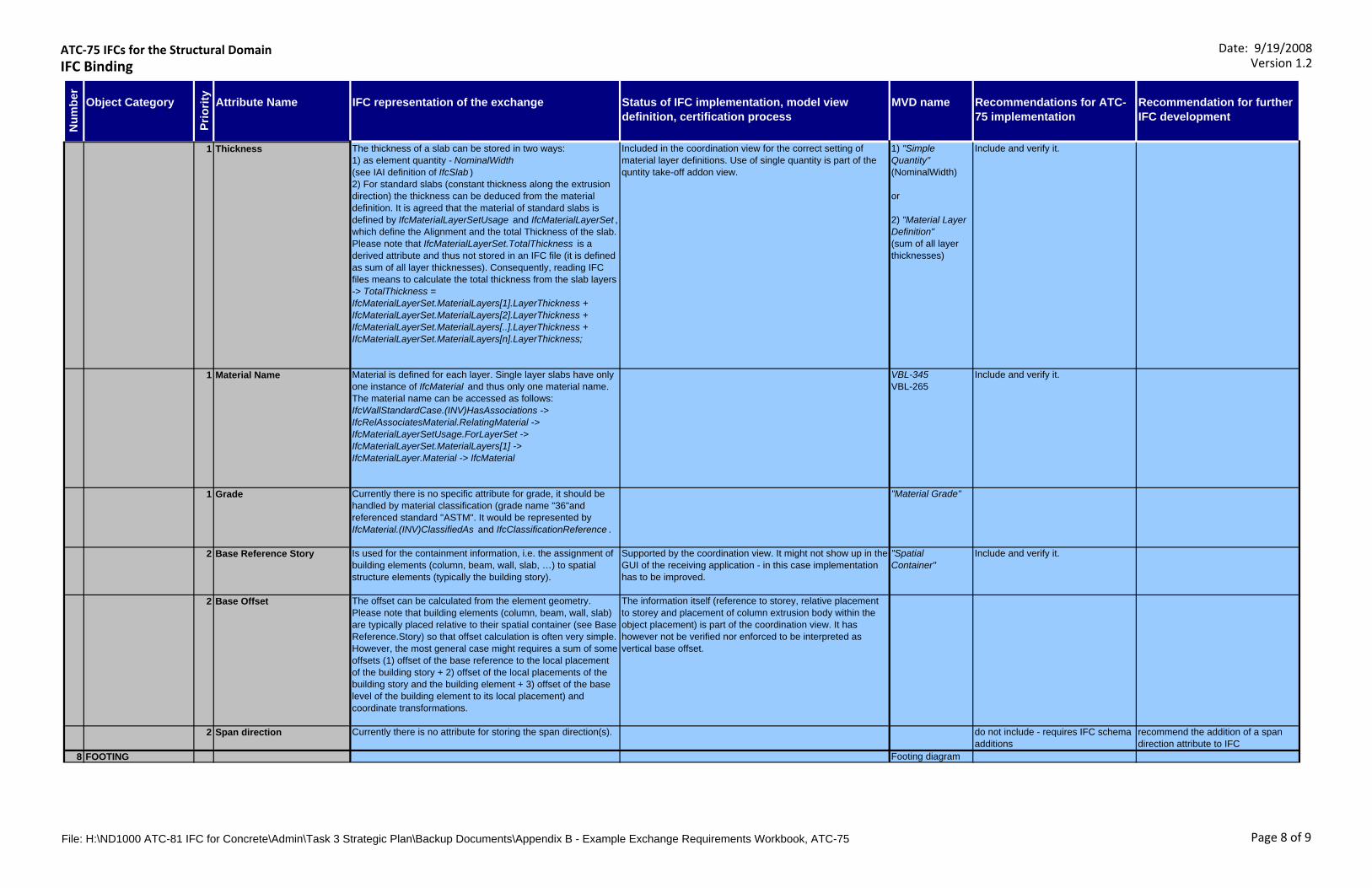
ATC‐75 IFCs for the Structural DomainIFC Binding
Date: 9/19/2008Version 1.2
Object Category Attribute Name IFC representation of the exchange Status of IFC implementation, model view definition, certification process
MVD name Recommendations for ATC-75 implementation
Recommendation for further IFC development
Num
ber
Prio
rity
1 Thickness The thickness of a slab can be stored in two ways:1) as element quantity - NominalWidth (see IAI definition of IfcSlab ) 2) For standard slabs (constant thickness along the extrusion direction) the thickness can be deduced from the material definition. It is agreed that the material of standard slabs is defined by IfcMaterialLayerSetUsage and IfcMaterialLayerSet , which define the Alignment and the total Thickness of the slab. Please note that IfcMaterialLayerSet.TotalThickness is a derived attribute and thus not stored in an IFC file (it is defined as sum of all layer thicknesses). Consequently, reading IFC files means to calculate the total thickness from the slab layers -> TotalThickness = IfcMaterialLayerSet.MaterialLayers[1].LayerThickness + IfcMaterialLayerSet.MaterialLayers[2].LayerThickness + IfcMaterialLayerSet.MaterialLayers[..].LayerThickness + IfcMaterialLayerSet.MaterialLayers[n].LayerThickness;
Included in the coordination view for the correct setting of material layer definitions. Use of single quantity is part of the quntity take-off addon view.
1) "Simple Quantity" (NominalWidth)
or
2) "Material Layer Definition" (sum of all layer thicknesses)
Include and verify it.
1 Material Name Material is defined for each layer. Single layer slabs have only one instance of IfcMaterial and thus only one material name. The material name can be accessed as follows: IfcWallStandardCase.(INV)HasAssociations -> IfcRelAssociatesMaterial.RelatingMaterial -> IfcMaterialLayerSetUsage.ForLayerSet ->IfcMaterialLayerSet.MaterialLayers[1] ->IfcMaterialLayer.Material -> IfcMaterial
VBL-345VBL-265
Include and verify it.
1 Grade Currently there is no specific attribute for grade, it should be handled by material classification (grade name "36"and referenced standard "ASTM". It would be represented by IfcMaterial.(INV)ClassifiedAs and IfcClassificationReference .
"Material Grade"
2 Base Reference Story Is used for the containment information, i.e. the assignment of building elements (column, beam, wall, slab, …) to spatial structure elements (typically the building story).
Supported by the coordination view. It might not show up in the GUI of the receiving application - in this case implementation has to be improved.
"Spatial Container"
Include and verify it.
2 Base Offset The offset can be calculated from the element geometry. Please note that building elements (column, beam, wall, slab) are typically placed relative to their spatial container (see Base Reference.Story) so that offset calculation is often very simple. However, the most general case might requires a sum of some offsets (1) offset of the base reference to the local placement of the building story + 2) offset of the local placements of the building story and the building element + 3) offset of the base level of the building element to its local placement) and coordinate transformations.
The information itself (reference to storey, relative placement to storey and placement of column extrusion body within the object placement) is part of the coordination view. It has however not be verified nor enforced to be interpreted as vertical base offset.
2 Span direction Currently there is no attribute for storing the span direction(s). do not include - requires IFC schema additions
recommend the addition of a span direction attribute to IFC
8 FOOTING Footing diagram
File: H:\ND1000 ATC-81 IFC for Concrete\Admin\Task 3 Strategic Plan\Backup Documents\Appendix B - Example Exchange Requirements Workbook, ATC-75 Page 8 of 9
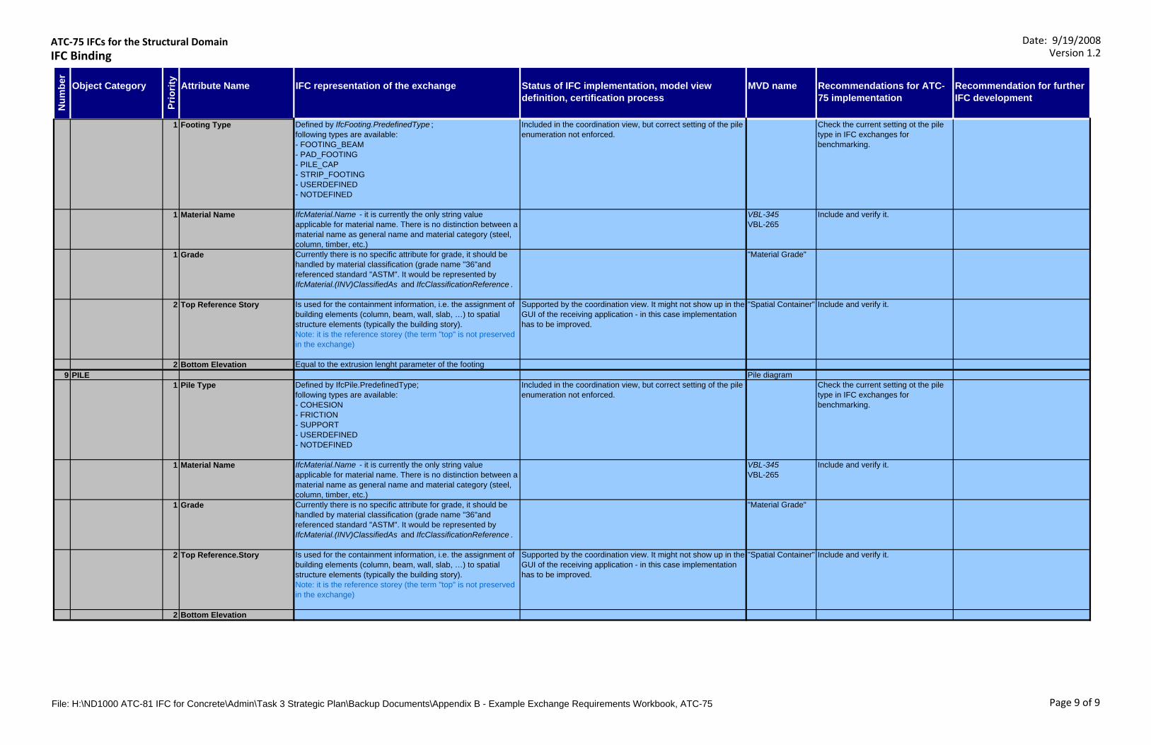
ATC‐75 IFCs for the Structural DomainIFC Binding
Date: 9/19/2008Version 1.2
Object Category Attribute Name IFC representation of the exchange Status of IFC implementation, model view definition, certification process
MVD name Recommendations for ATC-75 implementation
Recommendation for further IFC development
Num
ber
Prio
rity
1 Footing Type Defined by IfcFooting.PredefinedType ; following types are available: - FOOTING_BEAM- PAD_FOOTING- PILE_CAP- STRIP_FOOTING- USERDEFINED- NOTDEFINED
Included in the coordination view, but correct setting of the pile enumeration not enforced.
Check the current setting ot the pile type in IFC exchanges for benchmarking.
1 Material Name IfcMaterial.Name - it is currently the only string value applicable for material name. There is no distinction between a material name as general name and material category (steel, column, timber, etc.)
VBL-345VBL-265
Include and verify it.
1 Grade Currently there is no specific attribute for grade, it should be handled by material classification (grade name "36"and referenced standard "ASTM". It would be represented by IfcMaterial.(INV)ClassifiedAs and IfcClassificationReference .
"Material Grade"
2 Top Reference Story Is used for the containment information, i.e. the assignment of building elements (column, beam, wall, slab, …) to spatial structure elements (typically the building story). Note: it is the reference storey (the term "top" is not preserved in the exchange)
Supported by the coordination view. It might not show up in the GUI of the receiving application - in this case implementation has to be improved.
"Spatial Container" Include and verify it.
2 Bottom Elevation Equal to the extrusion lenght parameter of the footing9 PILE Pile diagram
1 Pile Type Defined by IfcPile.PredefinedType;following types are available:- COHESION- FRICTION- SUPPORT- USERDEFINED- NOTDEFINED
Included in the coordination view, but correct setting of the pile enumeration not enforced.
Check the current setting ot the pile type in IFC exchanges for benchmarking.
1 Material Name IfcMaterial.Name - it is currently the only string value applicable for material name. There is no distinction between a material name as general name and material category (steel, column, timber, etc.)
VBL-345VBL-265
Include and verify it.
1 Grade Currently there is no specific attribute for grade, it should be handled by material classification (grade name "36"and referenced standard "ASTM". It would be represented by IfcMaterial.(INV)ClassifiedAs and IfcClassificationReference .
"Material Grade"
2 Top Reference.Story Is used for the containment information, i.e. the assignment of building elements (column, beam, wall, slab, …) to spatial structure elements (typically the building story). Note: it is the reference storey (the term "top" is not preserved in the exchange)
Supported by the coordination view. It might not show up in the GUI of the receiving application - in this case implementation has to be improved.
"Spatial Container" Include and verify it.
2 Bottom Elevation
File: H:\ND1000 ATC-81 IFC for Concrete\Admin\Task 3 Strategic Plan\Backup Documents\Appendix B - Example Exchange Requirements Workbook, ATC-75 Page 9 of 9
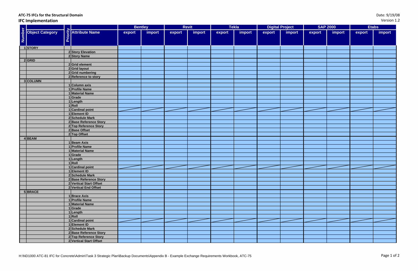
ATC‐75 IFCs for the Structural DomainIFC Implementation
Date: 9/19/08Version 1.2
Object Category Attribute Name export import export import export import export import export import export import
1 STORY2 Story Elevation2 Story Name
2 GRID2 Grid element2 Grid layout2 Grid numbering2 Reference to story
3 COLUMN1 Column axis1 Profile Name1 Material Name1 Grade1 Length1 Roll1 Cardinal point1 Element ID2 Schedule Mark2 Base Reference Story2 Top Reference Story2 Base Offset 2 Top Offset
4 BEAM1 Beam Axis1 Profile Name1 Material Name1 Grade1 Length1 Roll1 Cardinal point1 Element ID2 Schedule Mark2 Base Reference Story2 Vertical Start Offset2 Vertical End Offset
5 BRACE1 Brace Axis1 Profile Name1 Material Name1 Grade1 Length1 Roll1 Cardinal point1 Element ID2 Schedule Mark2 Base Reference Story2 Top Reference Story2 Vertical Start Offset
EtabsSAP 2000N
umbe
r
Prio
rity Bentley Revit Tekla Digital Project
H:\ND1000 ATC-81 IFC for Concrete\Admin\Task 3 Strategic Plan\Backup Documents\Appendix B - Example Exchange Requirements Workbook, ATC-75 Page 1 of 2

ATC‐75 IFCs for the Structural DomainIFC Implementation
Date: 9/19/08Version 1.2
Object Category Attribute Name export import export import export import export import export import export importEtabsSAP 2000
Num
ber
Prio
rity Bentley Revit Tekla Digital Project
2 Vertical End Offset6 WALL
1 Thickness1 Material Name1 Grade1 Wall Axis1 Alignment2 Base Reference Story2 Top Reference Story2 Base Offset 2 Top Offset2 Load bearing
7 SLAB1 Thickness1 Material Name1 Grade2 Base Reference Story2 Base Offset2 Span direction
8 FOOTING1 Footing Type1 Material Name1 Grade2 Top Reference Story2 Bottom Elevation
9 PILE1 Pile Type1 Material Name1 Grade2 Top Reference.Story2 Bottom Elevation
H:\ND1000 ATC-81 IFC for Concrete\Admin\Task 3 Strategic Plan\Backup Documents\Appendix B - Example Exchange Requirements Workbook, ATC-75 Page 2 of 2

Examples for column offsets to storys
Base Reference Story
Top Reference Story
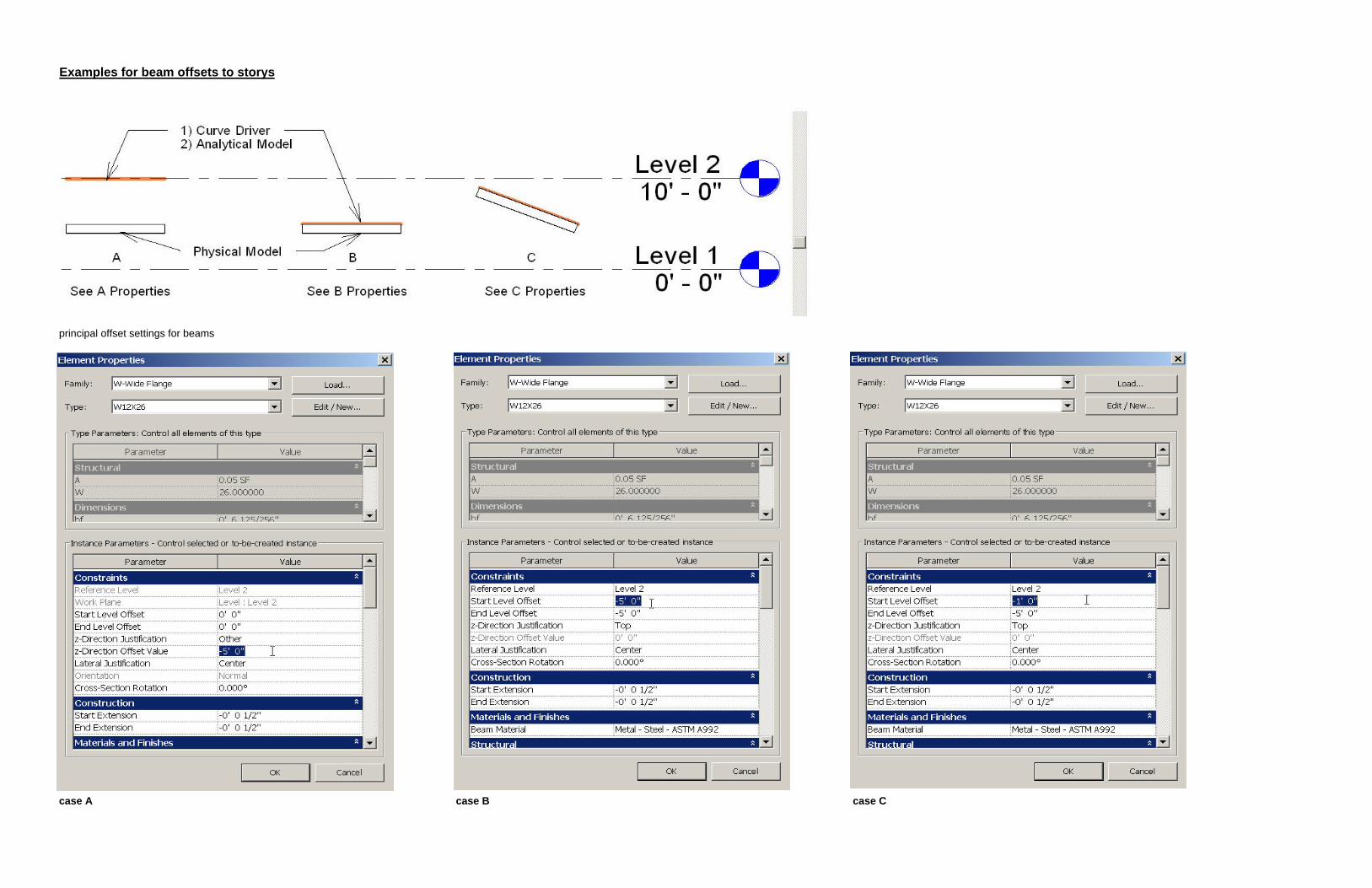
Examples for beam offsets to storys
principal offset settings for beams
case A case B case C
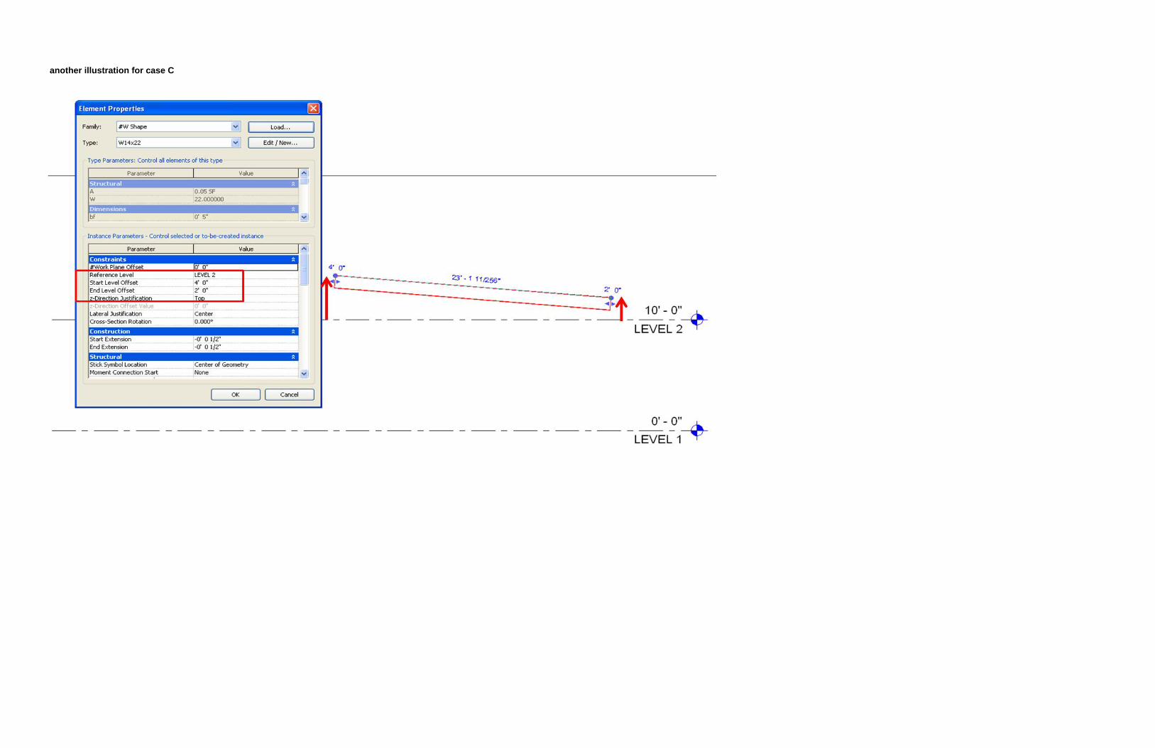
another illustration for case C
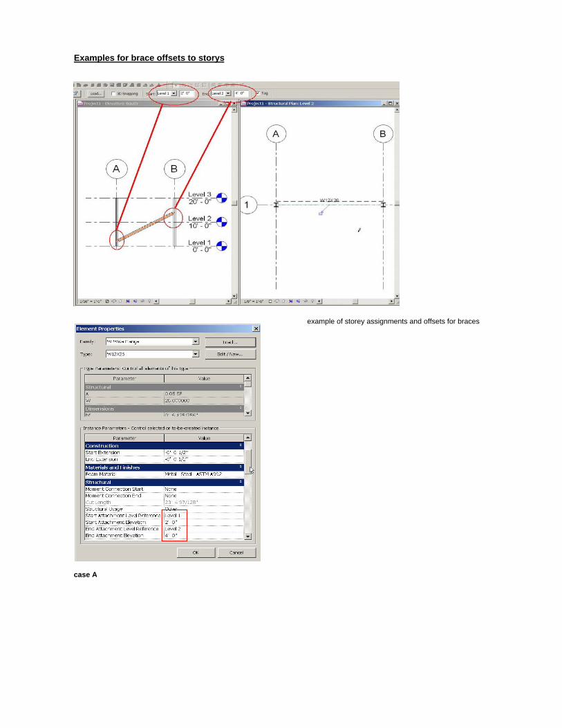
Examples for brace offsets to storys
example of storey assignments and offsets for braces
case A

appenDIX C:geometry attr ibutes
matr ix
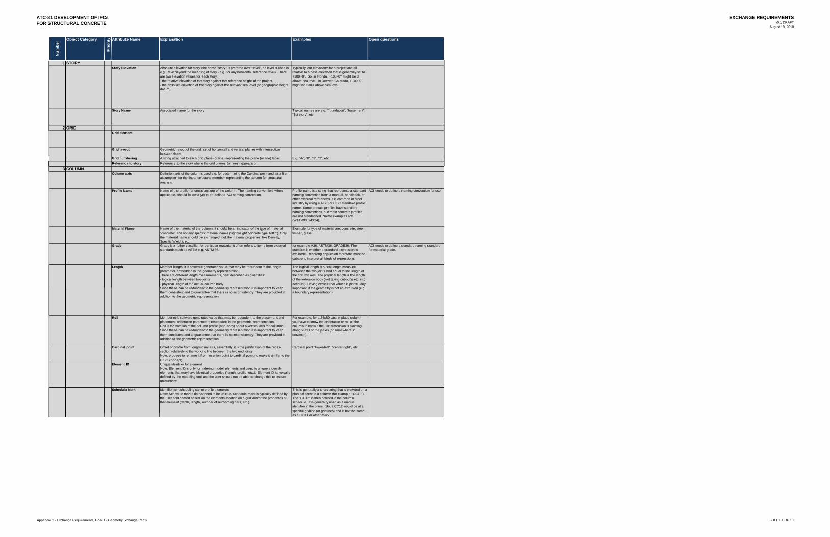
ATC-81 DEVELOPMENT OF IFCsFOR STRUCTURAL CONCRETE
EXCHANGE REQUIREMENTSv0.1 DRAFT
August 19, 2010
Num
ber Object Category
Prio
rity Attribute Name Explanation Examples Open questions
1 STORYStory Elevation Absolute elevation for story (the name "story" is prefered over "level", as level is used in
e.g. Revit beyond the meaning of story - e.g. for any horizontal reference level). There are two elevation values for each story:- the relative elevation of the story against the reference height of the project.- the absolute elevation of the story against the relevant sea level (or geographic height datum)
Typically, our elevations for a project are all relative to a base elevation that is generally set to +100'-0". So, in Florida, +100'-0'" might be 3' above sea level. In Denver, Colorado, +100'-0" might be 5300' above sea level.
Story Name Associated name for the story Typical names are e.g. "foundation", "basement", "1st story", etc.
2 GRIDGrid element
Grid layout Geometric layout of the grid, set of horizontal and vertical planes with intersection between them.
Grid numbering A string attached to each grid plane (or line) representing the plane (or line) label. E.g. "A", "B", "1", "2", etc.R f t t R f t th t h th id l ( li )Reference to story Reference to the story where the grid planes (or lines) appears on.
3 COLUMNColumn axis Definition axis of the column, used e.g. for determining the Cardinal point and as a first
assumption for the linear structural member representing the column for structural analysis.
Profile Name Name of the profile (or cross section) of the column. The naming convention, when applicable, should follow a yet-to-be-defined ACI naming convention.
Profile name is a string that represents a standard naming convention from a manual, handbook, or other external references. It is common in steel industry by using a AISC or CISC standard profile name. Some precast profiles have standard naming conventions, but most concrete profiles are not standarized. Name examples are (W14X90, 24X24).
ACI needs to define a naming convention for use.
Material Name Name of the material of the column. It should be an indicator of the type of material "concrete" and not any specific material name ("lightweight concrete type ABC"). Only the material name should be exchanged, not the material properties, like Density, Specific Weight, etc.
Example for type of material are: concrete, steel, timber, glass
Grade Grade is a futher classifier for particular material. It often refers to items from external standards such as ASTM e.g. ASTM 36.
for example A36, ASTM36, GRADE36. The question is whether a standard expression is available. Receiving applicaion therefore must be cabale to interpret all kinds of expressions.
ACI needs to define a standard naming standard for material grade.
Length Member length, it is software generated value that may be redundent to the length parameter embedded in the geometry representation.There are different length measurements, best described as quantities:- logical length between two joints- physical length of the actual column bodySince these can be redundent to the geometry representation it is importent to keep
The logical length is a real length measure between the two joints and equal to the length of the column axis. The physical length is the length of the extrusion body (not taking cut-out's etc. into account). Having explicit real values is particularly important if the geometry is not an extrusion (e gSince these can be redundent to the geometry representation it is importent to keep
them consistent and to guarantee that there is no inconsistency. They are provided in addition to the geometric representation.
important, if the geometry is not an extrusion (e.g. a boundary representation).
Roll Member roll, software generated value that may be redundent to the placement and placement orientation parameters embedded in the geometric representation.Roll is the rotation of the column profile (and body) about a vertical axis for columns. Since these can be redundent to the geometry representation it is importent to keep them consistent and to guarantee that there is no inconsistency. They are provided in addition to the geometric representation.
For example, for a 24x30 cast-in-place column, you have to know the orientation or roll of the column to know if the 30" dimension is pointing along x-axis or the y-axis (or somewhere in between).
Cardinal point Offset of profile from longitudinal axis, essentially, it is the justification of the cross-section relatively to the working line between the two end joints.Note: propose to rename it from insertion point to cardinal point (to make it similar to the CIS/2 concept).
Cardinal point "lower-left", "center-right", etc.
Element ID Unique identifier for elementNote: Element ID is only for indexing model elements and used to uniquely identify elements that may have identical properties (length, profile, etc.). Element ID is typically defined by the modeling tool and the user should not be able to change this to ensure uniqueness.
Schedule Mark Identifier for scheduling same profile elementsNote: Schedule marks do not need to be unique. Schedule mark is typically defined by the user and named based on the elements location on a grid and/or the properties of that element (depth, length, number of reinforcing bars, etc.).
This is generally a short string that is provided on a plan adjacent to a column (for example "CC12"). The "CC12" is then defined in the column schedule. It is generally used as a unique identifier in the plans. So, a CC12 would be at a specific gridline (or gridlines) and is not the same as a CC11 or other mark.
Appendix C - Exchange Requirements, Goal 1 - GeometryExchange Req's SHEET 1 OF 10
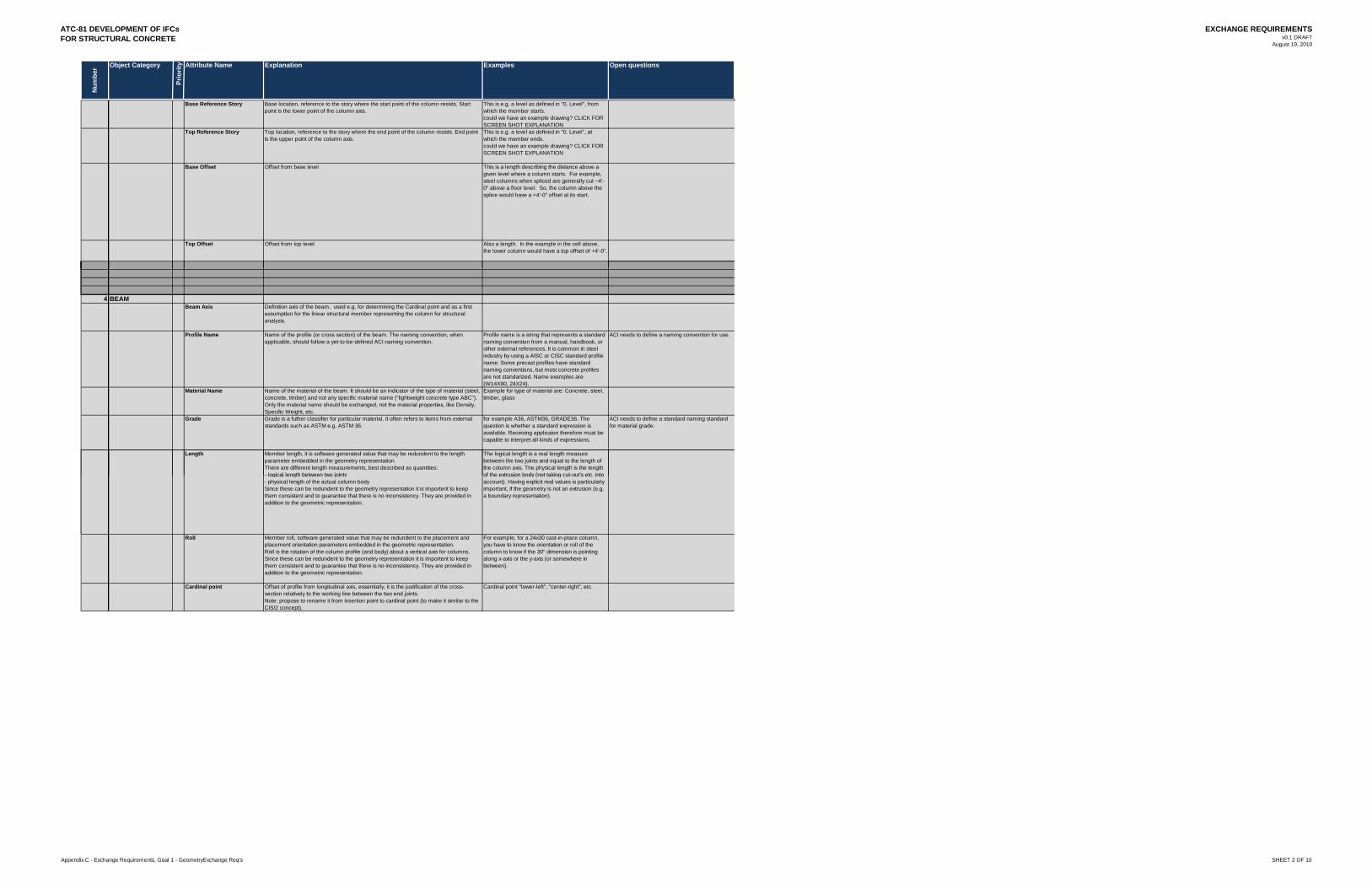
ATC-81 DEVELOPMENT OF IFCsFOR STRUCTURAL CONCRETE
EXCHANGE REQUIREMENTSv0.1 DRAFT
August 19, 2010
Num
ber Object Category
Prio
rity Attribute Name Explanation Examples Open questions
Base Reference Story Base location, reference to the story where the start point of the column resists. Start point is the lower point of the column axis.
This is e.g. a level as defined in "0. Level", from which the member starts.could we have an example drawing? CLICK FOR SCREEN SHOT EXPLANATION
Top Reference Story Top location, reference to the story where the end point of the column resists. End point is the upper point of the column axis.
This is e.g. a level as defined in "0. Level", at which the member ends.could we have an example drawing? CLICK FOR SCREEN SHOT EXPLANATION
Base Offset Offset from base level This is a length describing the distance above a given level where a column starts. For example, steel columns when spliced are generally cut ~4'-0" above a floor level. So, the column above the splice would have a +4'-0" offset at its start.
Top Offset Offset from top level Also a length. In the example in the cell above, the lower column would have a top offset of +4'-0".
4 BEAMBeam Axis Definition axis of the beam, used e.g. for determining the Cardinal point and as a first
assumption for the linear structural member representing the column for structural analysis.
Profile Name Name of the profile (or cross section) of the beam. The naming convention, when applicable, should follow a yet-to-be-defined ACI naming convention.
Profile name is a string that represents a standard naming convention from a manual, handbook, or other external references. It is common in steel industry by using a AISC or CISC standard profile name. Some precast profiles have standard naming conventions, but most concrete profiles are not standarized. Name examples are (W14X90, 24X24).
ACI needs to define a naming convention for use.
Material Name Name of the material of the beam. It should be an indicator of the type of material (steel, concrete, timber) and not any specific material name ("lightweight concrete type ABC"). Only the material name should be exchanged, not the material properties, like Density, Specific Weight, etc.
Example for type of material are: Concrete, steel, timber, glass
Grade Grade is a futher classifier for particular material. It often refers to items from external standards such as ASTM e.g. ASTM 36.
for example A36, ASTM36, GRADE36. The question is whether a standard expression is available. Receiving applicaion therefore must be capable to interpret all kinds of expressions.
ACI needs to define a standard naming standard for material grade.
Length Member length, it is software generated value that may be redundent to the length parameter embedded in the geometry representation.There are different length measurements, best described as quantities:- logical length between two joints
The logical length is a real length measure between the two joints and equal to the length of the column axis. The physical length is the length of the extrusion body (not taking cut-out's etc. into- logical length between two joints
- physical length of the actual column bodySince these can be redundent to the geometry representation it is importent to keep them consistent and to guarantee that there is no inconsistency. They are provided in addition to the geometric representation.
of the extrusion body (not taking cut-out s etc. into account). Having explicit real values is particularly important, if the geometry is not an extrusion (e.g. a boundary representation).
Roll Member roll, software generated value that may be redundent to the placement and placement orientation parameters embedded in the geometric representation.Roll is the rotation of the column profile (and body) about a vertical axis for columns. Since these can be redundent to the geometry representation it is importent to keep them consistent and to guarantee that there is no inconsistency. They are provided in addition to the geometric representation.
For example, for a 24x30 cast-in-place column, you have to know the orientation or roll of the column to know if the 30" dimension is pointing along x-axis or the y-axis (or somewhere in between).
Cardinal point Offset of profile from longitudinal axis, essentially, it is the justification of the cross-section relatively to the working line between the two end joints.Note: propose to rename it from insertion point to cardinal point (to make it similar to the CIS/2 concept).
Cardinal point "lower-left", "center-right", etc.
Appendix C - Exchange Requirements, Goal 1 - GeometryExchange Req's SHEET 2 OF 10
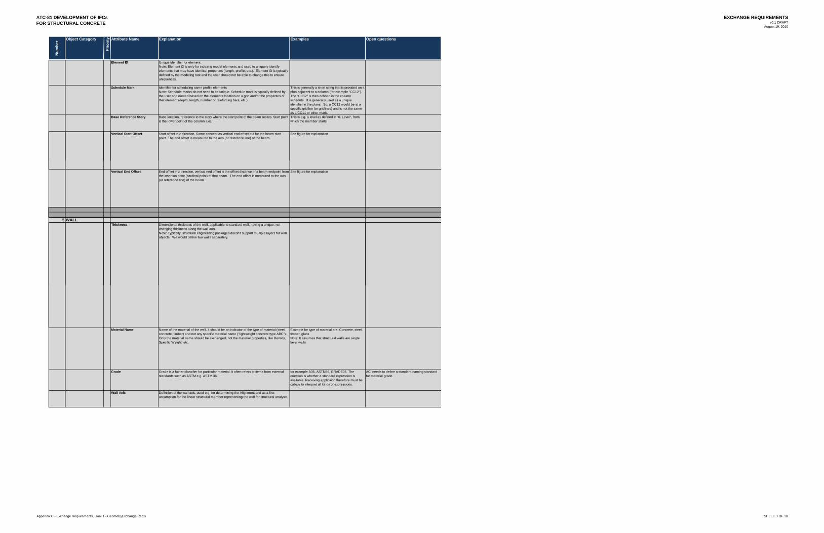
ATC-81 DEVELOPMENT OF IFCsFOR STRUCTURAL CONCRETE
EXCHANGE REQUIREMENTSv0.1 DRAFT
August 19, 2010
Num
ber Object Category
Prio
rity Attribute Name Explanation Examples Open questions
Element ID Unique identifier for elementNote: Element ID is only for indexing model elements and used to uniquely identify elements that may have identical properties (length, profile, etc.). Element ID is typically defined by the modeling tool and the user should not be able to change this to ensure uniqueness.
Schedule Mark Identifier for scheduling same profile elementsNote: Schedule marks do not need to be unique. Schedule mark is typically defined by the user and named based on the elements location on a grid and/or the properties of that element (depth, length, number of reinforcing bars, etc.).
This is generally a short string that is provided on a plan adjacent to a column (for example "CC12"). The "CC12" is then defined in the column schedule. It is generally used as a unique identifier in the plans. So, a CC12 would be at a specific gridline (or gridlines) and is not the same as a CC11 or other mark.
Base Reference Story Base location, reference to the story where the start point of the beam resists. Start point is the lower point of the column axis.
This is e.g. a level as defined in "0. Level", from which the member starts.
Vertical Start Offset Start offset in z direction, Same concept as vertical end offset but for the beam start point. The end offset is measured to the axis (or reference line) of the beam.
See figure for explanation
Vertical End Offset End offset in z direction, vertical end offset is the offset distance of a beam endpoint from the insertion point (cardinal point) of that beam. The end offset is measured to the axis (or reference line) of the beam.
See figure for explanation
5 WALLThickness Dimensional thickness of the wall, applicable to standard wall, having a unique, not-
changing thickness along the wall axis.Note: Typically, structural engineering packages doesn't support multiple layers for wall objects. We would define two walls separately.
Material Name Name of the material of the wall. It should be an indicator of the type of material (steel, concrete, timber) and not any specific material name ("lightweight concrete type ABC"). Only the material name should be exchanged, not the material properties, like Density, Specific Weight, etc.
Example for type of material are: Concrete, steel, timber, glassNote: It assumes that structural walls are single layer walls
Grade Grade is a futher classifier for particular material. It often refers to items from external standards such as ASTM e.g. ASTM 36.
for example A36, ASTM36, GRADE36. The question is whether a standard expression is available. Receiving applicaion therefore must be cabale to interpret all kinds of expressions.
ACI needs to define a standard naming standard for material grade.
Wall Axis Definition of the wall axis, used e.g. for determining the Alignment and as a first assumption for the linear structural member representing the wall for structural analysis.
Appendix C - Exchange Requirements, Goal 1 - GeometryExchange Req's SHEET 3 OF 10
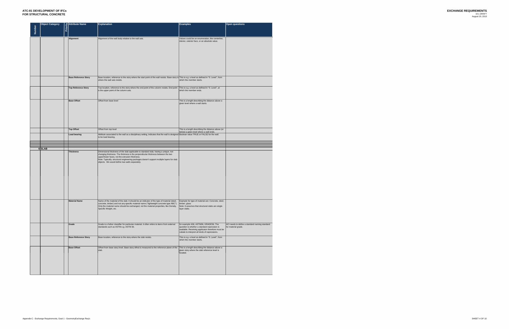
ATC-81 DEVELOPMENT OF IFCsFOR STRUCTURAL CONCRETE
EXCHANGE REQUIREMENTSv0.1 DRAFT
August 19, 2010
Num
ber Object Category
Prio
rity Attribute Name Explanation Examples Open questions
Alignment Alignment of the wall body relative to the wall axis. Values could be an enumeration, like centerline, interior, exterior face, or an absolute value.
Base Reference Story Base location, reference to the story where the start point of the wall resists. Base story is where the wall axis resists.
This is e.g. a level as defined in "0. Level", from which the member starts.
Top Reference Story Top location, reference to the story where the end point of the column resists. End point is the upper point of the column axis.
This is e.g. a level as defined in "0. Level", at which the member ends.
Base Offset Offset from base level This is a length describing the distance above a given level where a wall starts.
Top Offset Offset from top level This is a length describing the distance above (or below) a given level where a wall ends.
Load bearing Attribute associated to the wall as a disciplinary setting, indicates that the wall is designed to be load bearing.
Boolean value TRUE or FALSE for the wall.
6 SLABThickness Dimensional thickness of the slab applicable to standard slab, having a unique, not-
changing thickness. The thickness is the perpendicular thickness between the two upper/lower faces, not the extrusion thickness.Note: Typically, structural engineering packages doesn't support multiple layers for slab objects. We would define two walls separately.
Material Name Name of the material of the slab. It should be an indicator of the type of material (steel, concrete, timber) and not any specific material name ("lightweight concrete type ABC"). Only the material name should be exchanged, not the material properties, like Density, Specific Weight, etc.
Example for type of material are: Concrete, steel, timber, glassNote: It assumes that structural slabs are single layer slabs.
Grade Grade is a futher classifier for particular material. It often refers to items from external standards such as ASTM e.g. ASTM 36.
for example A36, ASTM36, GRADE36. The question is whether a standard expression is available. Receiving applicaion therefore must be cabale to interpret all kinds of expressions.
ACI needs to define a standard naming standard for material grade.
Base Reference Story Base location, reference to the story where the slab resists. This is e.g. a level as defined in "0. Level", from which the member starts.
Base Offset Offset from base story level. Base story offest is measured to the reference plane of the slab.
This is a length describing the distance above a given story where the slab reference level is located.located.
Appendix C - Exchange Requirements, Goal 1 - GeometryExchange Req's SHEET 4 OF 10
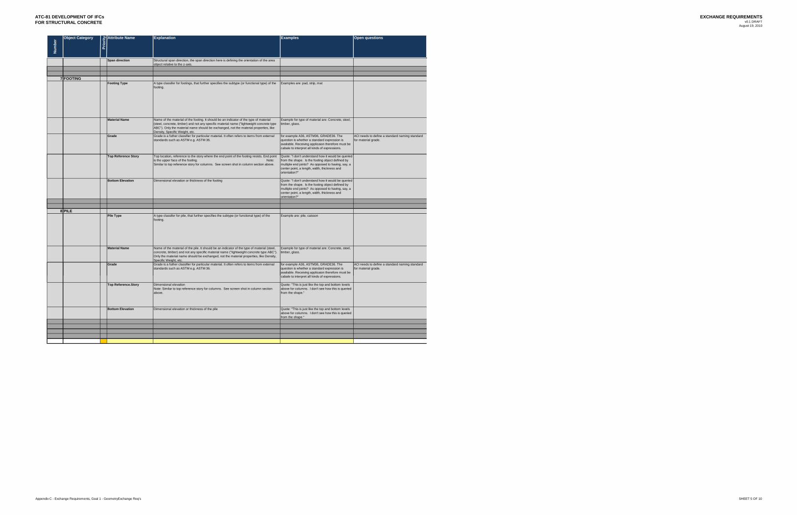
ATC-81 DEVELOPMENT OF IFCsFOR STRUCTURAL CONCRETE
EXCHANGE REQUIREMENTSv0.1 DRAFT
August 19, 2010
Num
ber Object Category
Prio
rity Attribute Name Explanation Examples Open questions
Span direction Structural span direction, the span direction here is defining the orientation of the area object relative to the z-axis.
7 FOOTINGFooting Type A type classifer for footings, that further specifies the subtype (or functional type) of the
footing.Examples are: pad, strip, mat
Material Name Name of the material of the footing. It should be an indicator of the type of material (steel, concrete, timber) and not any specific material name ("lightweight concrete type ABC"). Only the material name should be exchanged, not the material properties, like Density, Specific Weight, etc.
Example for type of material are: Concrete, steel, timber, glass.
Grade Grade is a futher classifier for particular material. It often refers to items from external standards such as ASTM e.g. ASTM 36.
for example A36, ASTM36, GRADE36. The question is whether a standard expression is available. Receiving applicaion therefore must be cabale to interpret all kinds of expressions.
ACI needs to define a standard naming standard for material grade.
Top Reference Story Top location reference to the story where the end point of the footing resists End point Quote: "I don't understand how it would be queriedTop Reference Story Top location, reference to the story where the end point of the footing resists. End point is the upper face of the footing. Note: Similar to top reference story for columns. See screen shot in column section above.
Quote: "I don't understand how it would be queried from the shape. Is the footing object defined by multiple end joints? As opposed to having, say, a center point, a length, width, thickness and orientation?"
Bottom Elevation Dimensional elevation or thickness of the footing Quote: "I don't understand how it would be queried from the shape. Is the footing object defined by multiple end joints? As opposed to having, say, a center point, a length, width, thickness and orientation?"
8 PILEPile Type A type classifer for pile, that further specifies the subtype (or functional type) of the
footing.Example are: pile, caisson
Material Name Name of the material of the pile. It should be an indicator of the type of material (steel, concrete, timber) and not any specific material name ("lightweight concrete type ABC"). Only the material name should be exchanged, not the material properties, like Density, Specific Weight, etc.
Example for type of material are: Concrete, steel, timber, glass.
Grade Grade is a futher classifier for particular material. It often refers to items from external standards such as ASTM e.g. ASTM 36.
for example A36, ASTM36, GRADE36. The question is whether a standard expression is available. Receiving applicaion therefore must be cabale to interpret all kinds of expressions
ACI needs to define a standard naming standard for material grade.
cabale to interpret all kinds of expressions.
Top Reference.Story Dimensional elevation Note: Similar to top reference story for columns. See screen shot in column section above.
Quote: "This is just like the top and bottom levels above for columns. I don't see how this is queried from the shape."
Bottom Elevation Dimensional elevation or thickness of the pile Quote: "This is just like the top and bottom levels above for columns. I don't see how this is queried from the shape."
Appendix C - Exchange Requirements, Goal 1 - GeometryExchange Req's SHEET 5 OF 10
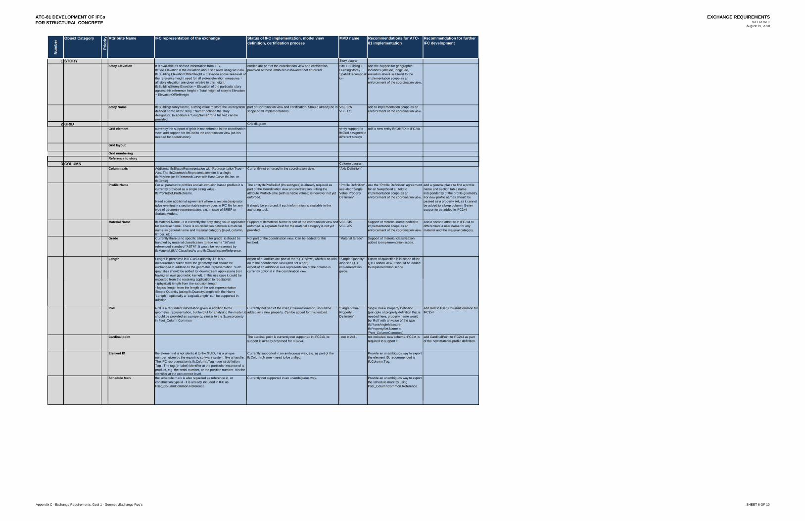
ATC-81 DEVELOPMENT OF IFCsFOR STRUCTURAL CONCRETE
EXCHANGE REQUIREMENTSv0.1 DRAFT
August 19, 2010
Num
ber Object Category
Prio
rity Attribute Name
1 STORYStory Elevation
Story Name
2 GRIDGrid element
Grid layout
Grid numberingR f t t
IFC representation of the exchange Status of IFC implementation, model view definition, certification process
MVD name Recommendations for ATC-81 implementation
Recommendation for further IFC development
Story diagramIt is available as derived information from IFC.IfcSite.Elevation is the elevation about sea level using WGS84IfcBuilding.ElevationOfRefHeight = Elevation above sea level of the reference height used for all storey elevation measures = all story elevation are given relative to this height.IfcBuildingStorey.Elevation = Elevation of the particular story against this reference height = Total height of story is Elevation + ElevationOfRefHeight
entities are part of the coordination view and certification, provision of these attributes is however not enforced.
Site + Building + BuildingStorey +SpatialDecomposition
add the support for geographic locations (latitude, longitude, elevation above sea level to the implementation scope as an enforcement of the coordination view.
IfcBuildingStorey.Name, a string value to store the user/system defined name of the story. "Name" defined the story designator, In addition a "LongName" for a full text can be provided.
part of Coordination view and certification. Should already be in scope of all implementations.
VBL-025VBL-171
add to implementation scope as an enforcement of the coordination view.
Grid diagramcurrently the support of grids is not enforced in the coordination view, add support for IfcGrid to the coordination view (as it is needed for coordination).
verify support for IfcGrid assigned to different storeys
add a new entity IfcGrid3D to IFC2x4
Reference to story
3 COLUMNColumn axis
Profile Name
Material Name
Grade
Length
Column diagramAdditional IfcShapeRepresentation with RepresentationType = Axis. The IfcGeometricRepresentationItem is a single IfcPolyline (or IfcTrimmedCurve with BaseCurve IfcLine, or IfcCircle)
Currently not enforced in the coordination view. "Axis Definition"
For all parametric profiles and all extrusion based profiles it is currently provided as a single string value - IfcProfileDef.ProfileName.
Need some additional agreement where a section designator (plus eventually a section table name) goes in IFC file for any type of geometry representation, e.g. in case of BREP or SurfaceModels.
The entity IfcProfileDef (it's subtypes) is already required as part of the Coordination view and certification. Filling the attribute ProfileName (with sensible values) is however not yet enforced.
It should be enforced, if such information is available in the authoring tool.
"Profile Definition" -see also "Single Value Property Definition"
use the "Profile Definition" agreement for all SweptSolid's. Add to implementation scope as an enforcement of the coordination view.
add a general place to find a profile name and section table name independently of the profile geometry. For now profile names should be passed as a property set, as it cannot be added to a brep column. Better support to be added in IFC2x4
IfcMaterial.Name - it is currently the only string value applicable for material name. There is no distinction between a material name as general name and material category (steel, column, timber, etc.)
Support of IfcMaterial.Name is part of the coordination view and enforced. A separate field for the material category is not yet provided.
VBL-345VBL-265
Support of material name added to implementation scope as an enforcement of the coordination view.
Add a second attribute in IFC2x4 to differentiate a user name for any material and the material category.
Currently there is no specific attribute for grade, it should be handled by material classification (grade name "36"and referenced standard "ASTM". It would be represented by IfcMaterial.(INV)ClassifiedAs and IfcClassificationReference.
Not part of the coordination view. Can be added for this testbed.
"Material Grade" Support of material classification added to implementation scope.
Lenght is perceived in IFC as a quantity, i.e. it is a measurement taken from the geometry that should be exchanged in addition to the geometric representation. Such quantities should be added for downstream applications (not having an own geometric kernel). In this use case it could be expected from the receiving application to reestablish:
export of quantities are part of the "QTO view", which is an add-on to the coordination view (and not a part).export of an additional axis representation of the column is currently optional in the coordination view.
"Simple Quantity" also see QTO implementation guide.
Export of quantities is in scope of the QTO addon view. It should be added to implementation scope.
Roll
Cardinal point
Element ID
Schedule Mark
expected from the receiving application to reestablish:- (physical) length from the extrusion length- logical length from the length of the axis representationSimple Quantity (using IfcQuantityLength with the Name 'Length'), optionally a "LogicalLength" can be supported in addition.
Roll is a redundent information given in addition to the geometric representation, but helpful for analysing the model, it should be provided as a property, similar to the Span property in Pset_ColumnCommon
Currently not part of the Pset_ColumnCommon, should be added as a new property. Can be added for this testbed.
"Single Value Property Definition"
Single Value Property Definition (principle of property definition that is needed here, property name would be 'Roll' with an value of the type IfcPlaneAngleMeasure;IfcPropertySet.Name = 'Pset_ColumnCommon')
add Roll to Pset_ColumnCommon for IFC2x4
The cardinal point is currently not supported in IFC2x3, ist support is already proposed for IFC2x4.
- not in 2x3 - not included, new schema IFC2x4 is required to support it.
add CardinalPoint to IFC2x4 as part of the new material-profile definition.
the element-id is not identical to the GUID, it is a unique number, given by the exporting software system, like a handle. The IFC representation is IfcColumn.Tag - see ist definition: Tag : The tag (or label) identifier at the particular instance of a product, e.g. the serial number, or the position number. It is the identifier at the occurrence level.
Currently supported in an ambiguous way, e.g. as part of the IfcColumn.Name - need to be unified.
Provide an unambiguos way to export the element ID, recommended is IfcColumn.Tag.
the schedule mark is also regarded as reference id, or construction type id - it is already included in IFC as Pset_ColumnCommon.Reference
Currently not supported in an unambiguous way. Provide an unambiguos way to export the schedule mark by using Pset_ColumnCommon.Reference
Appendix C - Exchange Requirements, Goal 1 - GeometryExchange Req's SHEET 6 OF 10
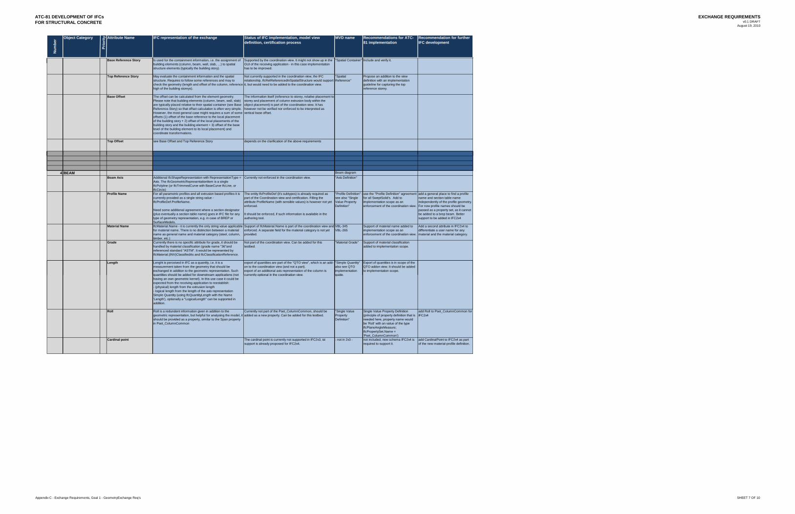
ATC-81 DEVELOPMENT OF IFCsFOR STRUCTURAL CONCRETE
EXCHANGE REQUIREMENTSv0.1 DRAFT
August 19, 2010
Num
ber Object Category
Prio
rity Attribute Name
Base Reference Story
Top Reference Story
Base Offset
Top Offset
IFC representation of the exchange Status of IFC implementation, model view definition, certification process
MVD name Recommendations for ATC-81 implementation
Recommendation for further IFC development
Is used for the containment information, i.e. the assignment of building elements (column, beam, wall, slab, …) to spatial structure elements (typically the building story).
Supported by the coordination view. It might not show up in the GUI of the receiving application - in this case implementation has to be improved.
"Spatial Container" Include and verify it.
May evaluate the containment information and the spatial structure. Requires to follow some references and may to check the geometry (length and offset of the column, reference high of the building storeys).
Not currently supported in the coordination view, the IFC relationship, IfcRelReferencedInSpatialStructure would support it, but would need to be added to the coordination view.
"Spatial Reference"
Propose an addition to the view definition with an implementation guideline for capturing the top reference storey.
The offset can be calculated from the element geometry. Please note that building elements (column, beam, wall, slab) are typically placed relative to their spatial container (see Base Reference.Story) so that offset calculation is often very simple. However, the most general case might requires a sum of some offsets (1) offset of the base reference to the local placement of the building story + 2) offset of the local placements of the building story and the building element + 3) offset of the base level of the building element to its local placement) and coordinate transformations.
The information itself (reference to storey, relative placement to storey and placement of column extrusion body within the object placement) is part of the coordination view. It has however not be verified nor enforced to be interpreted as vertical base offset.
see Base Offset and Top Reference.Story depends on the clarification of the above requirements
4 BEAMBeam Axis
Profile Name
Material Name
Grade
Length
Beam diagramAdditional IfcShapeRepresentation with RepresentationType = Axis. The IfcGeometricRepresentationItem is a single IfcPolyline (or IfcTrimmedCurve with BaseCurve IfcLine, or IfcCircle)
Currently not enforced in the coordination view. "Axis Definition"
For all parametric profiles and all extrusion based profiles it is currently provided as a single string value - IfcProfileDef.ProfileName.
Need some additional agreement where a section designator (plus eventually a section table name) goes in IFC file for any type of geometry representation, e.g. in case of BREP or SurfaceModels.
The entity IfcProfileDef (it's subtypes) is already required as part of the Coordination view and certification. Filling the attribute ProfileName (with sensible values) is however not yet enforced.
It should be enforced, if such information is available in the authoring tool.
"Profile Definition" -see also "Single Value Property Definition"
use the "Profile Definition" agreement for all SweptSolid's. Add to implementation scope as an enforcement of the coordination view.
add a general place to find a profile name and section table name independently of the profile geometry. For now profile names should be passed as a property set, as it cannot be added to a brep beam. Better support to be added in IFC2x4
IfcMaterial.Name - it is currently the only string value applicable for material name. There is no distinction between a material name as general name and material category (steel, column, timber, etc.)
Support of IfcMaterial.Name is part of the coordination view and enforced. A separate field for the material category is not yet provided.
VBL-345VBL-265
Support of material name added to implementation scope as an enforcement of the coordination view.
Add a second attribute in IFC2x4 to differentiate a user name for any material and the material category.
Currently there is no specific attribute for grade, it should be handled by material classification (grade name "36"and referenced standard "ASTM". It would be represented by IfcMaterial.(INV)ClassifiedAs and IfcClassificationReference.
Not part of the coordination view. Can be added for this testbed.
"Material Grade" Support of material classification added to implementation scope.
Lenght is perceived in IFC as a quantity, i.e. it is a measurement taken from the geometry that should be exchanged in addition to the geometric representation. Such quantities should be added for downstream applications (not
export of quantities are part of the "QTO view", which is an add-on to the coordination view (and not a part).export of an additional axis representation of the column is currently optional in the coordination view.
"Simple Quantity" also see QTO implementation guide.
Export of quantities is in scope of the QTO addon view. It should be added to implementation scope.
Roll
Cardinal point
quantities should be added for downstream applications (not having an own geometric kernel). In this use case it could be expected from the receiving application to reestablish:- (physical) length from the extrusion length- logical length from the length of the axis representationSimple Quantity (using IfcQuantityLength with the Name 'Length'), optionally a "LogicalLength" can be supported in addition.
currently optional in the coordination view. guide.
Roll is a redundent information given in addition to the geometric representation, but helpful for analysing the model, it should be provided as a property, similar to the Span property in Pset_ColumnCommon
Currently not part of the Pset_ColumnCommon, should be added as a new property. Can be added for this testbed.
"Single Value Property Definition"
Single Value Property Definition (principle of property definition that is needed here, property name would be 'Roll' with an value of the type IfcPlaneAngleMeasure;IfcPropertySet.Name = 'Pset_ColumnCommon')
add Roll to Pset_ColumnCommon for IFC2x4
The cardinal point is currently not supported in IFC2x3, ist support is already proposed for IFC2x4.
- not in 2x3 - not included, new schema IFC2x4 is required to support it.
add CardinalPoint to IFC2x4 as part of the new material-profile definition.
Appendix C - Exchange Requirements, Goal 1 - GeometryExchange Req's SHEET 7 OF 10
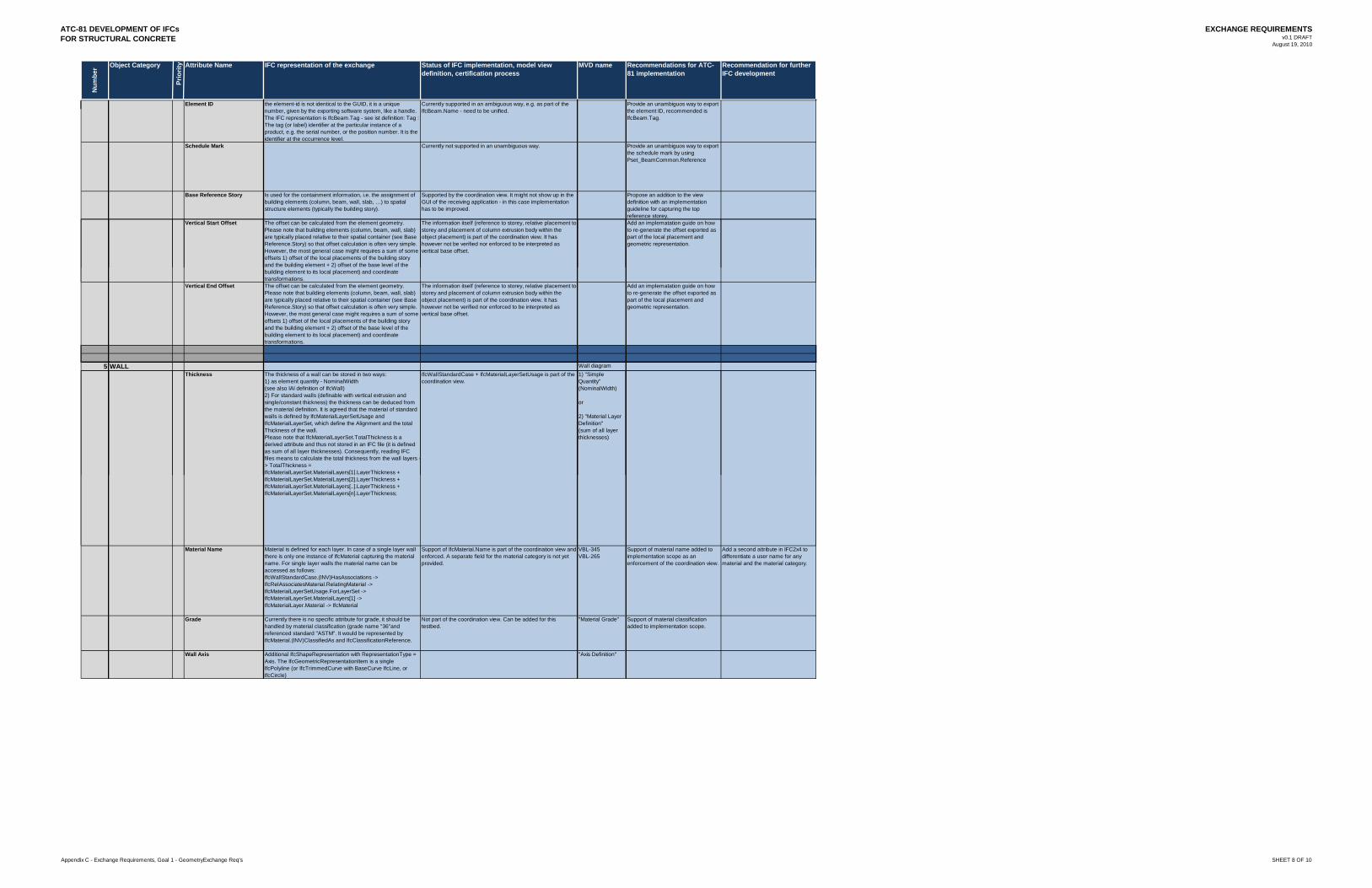
ATC-81 DEVELOPMENT OF IFCsFOR STRUCTURAL CONCRETE
EXCHANGE REQUIREMENTSv0.1 DRAFT
August 19, 2010
Num
ber Object Category
Prio
rity Attribute Name
Element ID
Schedule Mark
Base Reference Story
Vertical Start Offset
IFC representation of the exchange Status of IFC implementation, model view definition, certification process
MVD name Recommendations for ATC-81 implementation
Recommendation for further IFC development
the element-id is not identical to the GUID, it is a unique number, given by the exporting software system, like a handle. The IFC representation is IfcBeam.Tag - see ist definition: Tag : The tag (or label) identifier at the particular instance of a product, e.g. the serial number, or the position number. It is the identifier at the occurrence level.
Currently supported in an ambiguous way, e.g. as part of the IfcBeam.Name - need to be unified.
Provide an unambiguos way to export the element ID, recommended is IfcBeam.Tag.
Currently not supported in an unambiguous way. Provide an unambiguos way to export the schedule mark by using Pset_BeamCommon.Reference
Is used for the containment information, i.e. the assignment of building elements (column, beam, wall, slab, …) to spatial structure elements (typically the building story).
Supported by the coordination view. It might not show up in the GUI of the receiving application - in this case implementation has to be improved.
Propose an addition to the view definition with an implementation guideline for capturing the top reference storey.
The offset can be calculated from the element geometry. Please note that building elements (column, beam, wall, slab) are typically placed relative to their spatial container (see Base Reference.Story) so that offset calculation is often very simple. However, the most general case might requires a sum of some offsets 1) offset of the local placements of the building story and the building element + 2) offset of the base level of the
The information itself (reference to storey, relative placement to storey and placement of column extrusion body within the object placement) is part of the coordination view. It has however not be verified nor enforced to be interpreted as vertical base offset.
Add an implematation guide on how to re-generate the offset exported as part of the local placement and geometric representation.
Vertical End Offset
5 WALLThickness
g )building element to its local placement) and coordinate transformations. The offset can be calculated from the element geometry. Please note that building elements (column, beam, wall, slab) are typically placed relative to their spatial container (see Base Reference.Story) so that offset calculation is often very simple. However, the most general case might requires a sum of some offsets 1) offset of the local placements of the building story and the building element + 2) offset of the base level of the building element to its local placement) and coordinate transformations.
The information itself (reference to storey, relative placement to storey and placement of column extrusion body within the object placement) is part of the coordination view. It has however not be verified nor enforced to be interpreted as vertical base offset.
Add an implematation guide on how to re-generate the offset exported as part of the local placement and geometric representation.
Wall diagramThe thickness of a wall can be stored in two ways:1) as element quantity - NominalWidth (see also IAI definition of IfcWall) 2) For standard walls (definable with vertical extrusion and single/constant thickness) the thickness can be deduced from the material definition. It is agreed that the material of standard walls is defined by IfcMaterialLayerSetUsage and IfcMaterialLayerSet, which define the Alignment and the total Thickness of the wall. Please note that IfcMaterialLayerSet.TotalThickness is a derived attribute and thus not stored in an IFC file (it is defined as sum of all layer thicknesses). Consequently, reading IFC files means to calculate the total thickness from the wall layers -> TotalThickness = IfcMaterialLayerSet.MaterialLayers[1].LayerThickness +
IfcWallStandardCase + IfcMaterialLayerSetUsage is part of the coordination view.
1) "Simple Quantity" (NominalWidth)
or
2) "Material Layer Definition" (sum of all layer thicknesses)
Material Name
Grade
Wall Axis
y y [ ] yIfcMaterialLayerSet.MaterialLayers[2].LayerThickness + IfcMaterialLayerSet.MaterialLayers[..].LayerThickness + IfcMaterialLayerSet.MaterialLayers[n].LayerThickness;
Material is defined for each layer. In case of a single layer wall there is only one instance of IfcMaterial capturing the material name. For single layer walls the material name can be accessed as follows: IfcWallStandardCase.(INV)HasAssociations -> IfcRelAssociatesMaterial.RelatingMaterial -> IfcMaterialLayerSetUsage.ForLayerSet ->IfcMaterialLayerSet.MaterialLayers[1] ->IfcMaterialLayer.Material -> IfcMaterial
Support of IfcMaterial.Name is part of the coordination view and enforced. A separate field for the material category is not yet provided.
VBL-345VBL-265
Support of material name added to implementation scope as an enforcement of the coordination view.
Add a second attribute in IFC2x4 to differentiate a user name for any material and the material category.
Currently there is no specific attribute for grade, it should be handled by material classification (grade name "36"and referenced standard "ASTM". It would be represented by IfcMaterial.(INV)ClassifiedAs and IfcClassificationReference.
Not part of the coordination view. Can be added for this testbed.
"Material Grade" Support of material classification added to implementation scope.
Additional IfcShapeRepresentation with RepresentationType = Axis. The IfcGeometricRepresentationItem is a single IfcPolyline (or IfcTrimmedCurve with BaseCurve IfcLine, or IfcCircle)
"Axis Definition"
Appendix C - Exchange Requirements, Goal 1 - GeometryExchange Req's SHEET 8 OF 10
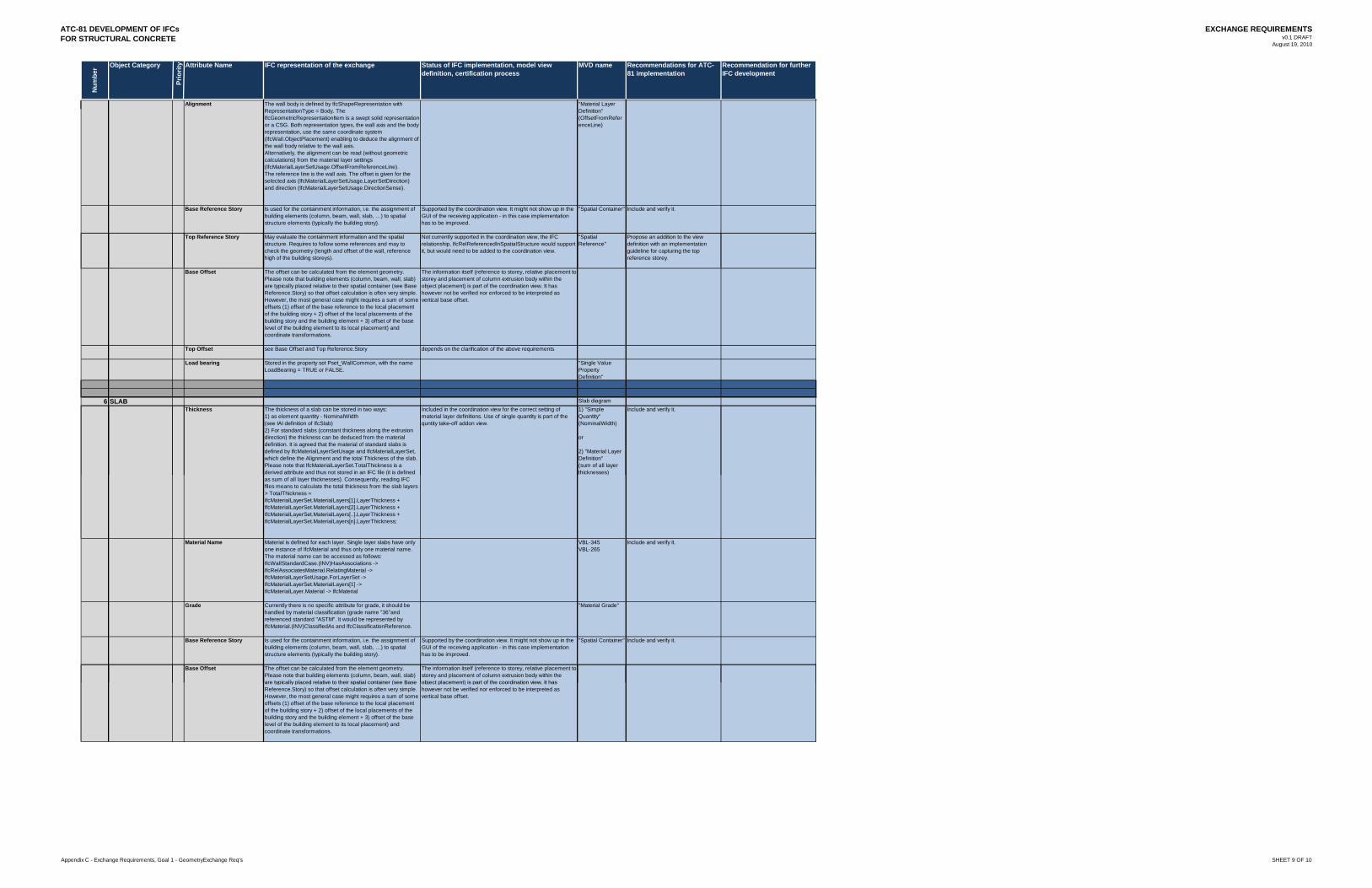
ATC-81 DEVELOPMENT OF IFCsFOR STRUCTURAL CONCRETE
EXCHANGE REQUIREMENTSv0.1 DRAFT
August 19, 2010
Num
ber Object Category
Prio
rity Attribute Name
Alignment
Base Reference Story
Top Reference Story
IFC representation of the exchange Status of IFC implementation, model view definition, certification process
MVD name Recommendations for ATC-81 implementation
Recommendation for further IFC development
The wall body is defined by IfcShapeRepresentation with RepresentationType = Body. The IfcGeometricRepresentationItem is a swept solid representation or a CSG. Both representation types, the wall axis and the body representation, use the same coordinate system (IfcWall.ObjectPlacement) enabling to deduce the alignment of the wall body relative to the wall axis.Alternatively, the alignment can be read (without geometric calculations) from the material layer settings (IfcMaterialLayerSetUsage.OffsetFromReferenceLine). The reference line is the wall axis. The offset is given for the selected axis (IfcMaterialLayerSetUsage.LayerSetDirection) and direction (IfcMaterialLayerSetUsage.DirectionSense).
"Material Layer Definition" (OffsetFromReferenceLine)
Is used for the containment information, i.e. the assignment of building elements (column, beam, wall, slab, …) to spatial structure elements (typically the building story).
Supported by the coordination view. It might not show up in the GUI of the receiving application - in this case implementation has to be improved.
"Spatial Container" Include and verify it.
May evaluate the containment information and the spatial structure. Requires to follow some references and may to check the geometry (length and offset of the wall, reference high of the building storeys).
Not currently supported in the coordination view, the IFC relationship, IfcRelReferencedInSpatialStructure would support it, but would need to be added to the coordination view.
"Spatial Reference"
Propose an addition to the view definition with an implementation guideline for capturing the top reference storey.
Base Offset
Top Offset
Load bearing
6 SLABThickness
The offset can be calculated from the element geometry. Please note that building elements (column, beam, wall, slab) are typically placed relative to their spatial container (see Base Reference.Story) so that offset calculation is often very simple. However, the most general case might requires a sum of some offsets (1) offset of the base reference to the local placement of the building story + 2) offset of the local placements of the building story and the building element + 3) offset of the base level of the building element to its local placement) and coordinate transformations.
The information itself (reference to storey, relative placement to storey and placement of column extrusion body within the object placement) is part of the coordination view. It has however not be verified nor enforced to be interpreted as vertical base offset.
see Base Offset and Top Reference.Story depends on the clarification of the above requirements
Stored in the property set Pset_WallCommon, with the name LoadBearing = TRUE or FALSE.
"Single Value Property Definition"
Slab diagramThe thickness of a slab can be stored in two ways:1) as element quantity - NominalWidth (see IAI definition of IfcSlab) 2) For standard slabs (constant thickness along the extrusion direction) the thickness can be deduced from the material definition. It is agreed that the material of standard slabs is defined by IfcMaterialLayerSetUsage and IfcMaterialLayerSet, which define the Alignment and the total Thickness of the slab. Please note that IfcMaterialLayerSet.TotalThickness is a derived attribute and thus not stored in an IFC file (it is defined
Included in the coordination view for the correct setting of material layer definitions. Use of single quantity is part of the quntity take-off addon view.
1) "Simple Quantity" (NominalWidth)
or
2) "Material Layer Definition" (sum of all layer thicknesses)
Include and verify it.
Material Name
Grade
Base Reference Story
Base Offset
(as sum of all layer thicknesses). Consequently, reading IFC files means to calculate the total thickness from the slab layers -> TotalThickness = IfcMaterialLayerSet.MaterialLayers[1].LayerThickness + IfcMaterialLayerSet.MaterialLayers[2].LayerThickness + IfcMaterialLayerSet.MaterialLayers[..].LayerThickness + IfcMaterialLayerSet.MaterialLayers[n].LayerThickness;
)
Material is defined for each layer. Single layer slabs have only one instance of IfcMaterial and thus only one material name. The material name can be accessed as follows: IfcWallStandardCase.(INV)HasAssociations -> IfcRelAssociatesMaterial.RelatingMaterial -> IfcMaterialLayerSetUsage.ForLayerSet ->IfcMaterialLayerSet.MaterialLayers[1] ->IfcMaterialLayer.Material -> IfcMaterial
VBL-345VBL-265
Include and verify it.
Currently there is no specific attribute for grade, it should be handled by material classification (grade name "36"and referenced standard "ASTM". It would be represented by IfcMaterial.(INV)ClassifiedAs and IfcClassificationReference.
"Material Grade"
Is used for the containment information, i.e. the assignment of building elements (column, beam, wall, slab, …) to spatial structure elements (typically the building story).
Supported by the coordination view. It might not show up in the GUI of the receiving application - in this case implementation has to be improved.
"Spatial Container" Include and verify it.
The offset can be calculated from the element geometry. Please note that building elements (column, beam, wall, slab) are typically placed relative to their spatial container (see Base
The information itself (reference to storey, relative placement to storey and placement of column extrusion body within the object placement) is part of the coordination view. It hasare typically placed relative to their spatial container (see Base
Reference.Story) so that offset calculation is often very simple. However, the most general case might requires a sum of some offsets (1) offset of the base reference to the local placement of the building story + 2) offset of the local placements of the building story and the building element + 3) offset of the base level of the building element to its local placement) and coordinate transformations.
object placement) is part of the coordination view. It has however not be verified nor enforced to be interpreted as vertical base offset.
Appendix C - Exchange Requirements, Goal 1 - GeometryExchange Req's SHEET 9 OF 10
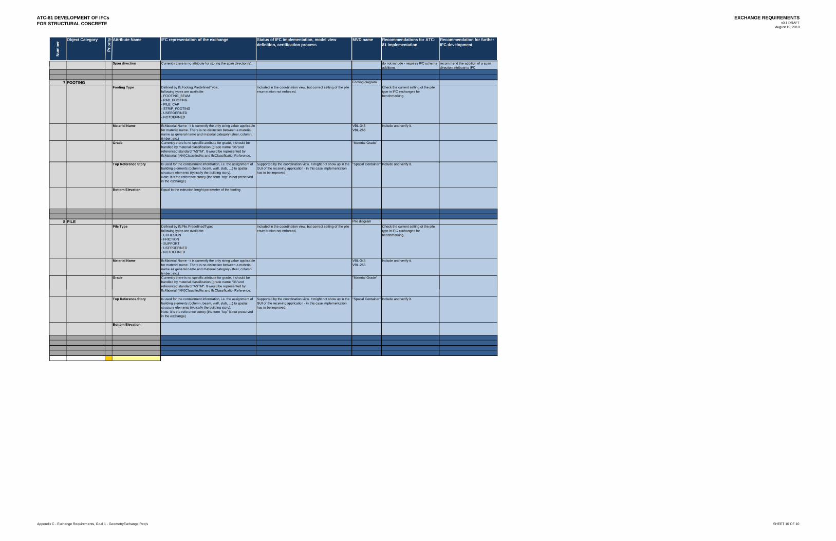
ATC-81 DEVELOPMENT OF IFCsFOR STRUCTURAL CONCRETE
EXCHANGE REQUIREMENTSv0.1 DRAFT
August 19, 2010
Num
ber Object Category
Prio
rity Attribute Name
Span direction
7 FOOTINGFooting Type
Material Name
Grade
Top Reference Story
IFC representation of the exchange Status of IFC implementation, model view definition, certification process
MVD name Recommendations for ATC-81 implementation
Recommendation for further IFC development
Currently there is no attribute for storing the span direction(s). do not include - requires IFC schema additions
recommend the addition of a span direction attribute to IFC
Footing diagramDefined by IfcFooting.PredefinedType; following types are available: - FOOTING_BEAM- PAD_FOOTING- PILE_CAP- STRIP_FOOTING- USERDEFINED- NOTDEFINED
Included in the coordination view, but correct setting of the pile enumeration not enforced.
Check the current setting ot the pile type in IFC exchanges for benchmarking.
IfcMaterial.Name - it is currently the only string value applicable for material name. There is no distinction between a material name as general name and material category (steel, column, timber, etc.)
VBL-345VBL-265
Include and verify it.
Currently there is no specific attribute for grade, it should be handled by material classification (grade name "36"and referenced standard "ASTM". It would be represented by IfcMaterial.(INV)ClassifiedAs and IfcClassificationReference.
"Material Grade"
Is used for the containment information i e the assignment of Supported by the coordination view It might not show up in the "Spatial Container" Include and verify itTop Reference Story
Bottom Elevation
8 PILEPile Type
Material Name
Grade
Is used for the containment information, i.e. the assignment of building elements (column, beam, wall, slab, …) to spatial structure elements (typically the building story). Note: it is the reference storey (the term "top" is not preserved in the exchange)
Supported by the coordination view. It might not show up in the GUI of the receiving application - in this case implementation has to be improved.
"Spatial Container" Include and verify it.
Equal to the extrusion lenght parameter of the footing
Pile diagramDefined by IfcPile.PredefinedType;following types are available:- COHESION- FRICTION- SUPPORT- USERDEFINED- NOTDEFINED
Included in the coordination view, but correct setting of the pile enumeration not enforced.
Check the current setting ot the pile type in IFC exchanges for benchmarking.
IfcMaterial.Name - it is currently the only string value applicable for material name. There is no distinction between a material name as general name and material category (steel, column, timber, etc.)
VBL-345VBL-265
Include and verify it.
Currently there is no specific attribute for grade, it should be handled by material classification (grade name "36"and referenced standard "ASTM". It would be represented by IfcMaterial (INV)ClassifiedAs and IfcClassificationReference
"Material Grade"
Top Reference.Story
Bottom Elevation
IfcMaterial.(INV)ClassifiedAs and IfcClassificationReference.
Is used for the containment information, i.e. the assignment of building elements (column, beam, wall, slab, …) to spatial structure elements (typically the building story). Note: it is the reference storey (the term "top" is not preserved in the exchange)
Supported by the coordination view. It might not show up in the GUI of the receiving application - in this case implementation has to be improved.
"Spatial Container" Include and verify it.
Appendix C - Exchange Requirements, Goal 1 - GeometryExchange Req's SHEET 10 OF 10

appenDIX D :Re inforcement
attr ibutes matr ix
ATC-81 DEVELOPMENT OF IFCsFOR STRUCTURAL CONCRETE
EXCHANGE REQUIREMENTSv0.1 DRAFT
August 19, 2010
Num
ber Object Category
Prio
rity Attribute Name Explanation Examples Open questions
Appendix D - Exchange Requirements, Goal 2 - ReinforcementExchange Req's SHEET 1 OF 2

ATC-81 DEVELOPMENT OF IFCsFOR STRUCTURAL CONCRETE
EXCHANGE REQUIREMENTSv0.1 DRAFT
August 19, 2010
Num
ber Object Category
Prio
rity Attribute Name IFC representation of the exchange Status of IFC implementation, model view
definition, certification processMVD name Recommendations for ATC-
81 implementationRecommendation for further IFC development
Appendix D - Exchange Requirements, Goal 2 - ReinforcementExchange Req's SHEET 2 OF 2

appenDIX e :Concrete mater ia ls
attr ibutes matr ix

ATC-81 DEVELOPMENT OF IFCsFOR STRUCTURAL CONCRETE
EXCHANGE REQUIREMENTSv0.1 DRAFT
August 19, 2010
Num
ber Object Category
Prio
rity Attribute Name Explanation Examples Open questions
Appendix E - Exchange Requirements, Goal 3 - Concrete MaterialsExchange Req's SHEET 1 OF 2

ATC-81 DEVELOPMENT OF IFCsFOR STRUCTURAL CONCRETE
EXCHANGE REQUIREMENTSv0.1 DRAFT
August 19, 2010
Num
ber Object Category
Prio
rity Attribute Name IFC representation of the exchange Status of IFC implementation, model view
definition, certification processMVD name Recommendations for ATC-
81 implementationRecommendation for further IFC development
Appendix E - Exchange Requirements, Goal 3 - Concrete MaterialsExchange Req's SHEET 2 OF 2

appenDIX f :pro ject
management attr ibutes matr ix

ATC-81 DEVELOPMENT OF IFCsFOR STRUCTURAL CONCRETE
EXCHANGE REQUIREMENTSv0.1 DRAFT
August 19, 2010
Num
ber Object Category
Prio
rity Attribute Name Explanation Examples Open questions
Appendix F - Exchange Requirements, Goal 4 - Project ManagementExchange Req's SHEET 1 OF 2

ATC-81 DEVELOPMENT OF IFCsFOR STRUCTURAL CONCRETE
EXCHANGE REQUIREMENTSv0.1 DRAFT
August 19, 2010
Num
ber Object Category
Prio
rity Attribute Name IFC representation of the exchange Status of IFC implementation, model view
definition, certification processMVD name Recommendations for ATC-
81 implementationRecommendation for further IFC development
Appendix F - Exchange Requirements, Goal 4 - Project ManagementExchange Req's SHEET 2 OF 2

appenDIX g:formwork
attr ibutes matr ix

ATC-81 DEVELOPMENT OF IFCsFOR STRUCTURAL CONCRETE
EXCHANGE REQUIREMENTSv0.1 DRAFT
August 19, 2010
Num
ber Object Category
Prio
rity Attribute Name Explanation Examples Open questions
Appendix G - Exchange Requirements, Goal 5 - FormworkExchange Req's SHEET 1 OF 2
ATC-81 DEVELOPMENT OF IFCsFOR STRUCTURAL CONCRETE
EXCHANGE REQUIREMENTSv0.1 DRAFT
August 19, 2010
Num
ber Object Category
Prio
rity Attribute Name IFC representation of the exchange Status of IFC implementation, model view
definition, certification processMVD name Recommendations for ATC-
81 implementationRecommendation for further IFC development
Appendix G - Exchange Requirements, Goal 5 - FormworkExchange Req's SHEET 2 OF 2


