AbstractThis study establishes a tool condition monitoring methodology builds on the vibration signal attained via data acquisi-tion system which is integrated with the in house developed adaptive controller for an end milling. As the quality of the products and the machine tool performance are the key parameters in maintaining machine stability. Proposed Adaptive control optimization system is validated with the experimentation trials and data analysis on 3 axis CNC milling machine. The rotational speed of the spindle and vibration signals is found to be reactive to milling cutter condition and therefore capable of sustaining the set-out methodology. A novel hybrid transformation, coupled with FFT and HHT is proposed to distinguish between a source of variation for adaptive control optimization, cutting region with the non-cutting region. In this study, decisions are made to evaluate the tool condition by combining all related information into a rule base. The investigation trajectories unveil the established system be able to accomplish the mechanism properly as anticipated.
Usually, throughout the machining process, 3 diverse vibrations can arise owing to the absence of rigidity of soli-tary or numerous essentials of the system composed by the tool holder, machine tool, workpiece and cutting tool material. These vibrations are well known as free vibra-tions, forced vibrations and self-excited vibrations. Free vibrations take place as soon as the mechanical system is displaced from its equilibrium and is permitted to vibrate without restraint. Forced vibrations emerge owing to out-side excitations. Every tooth on the milling cutter enters and exits the workpiece is identified as the primary cause of forced vibrations in the milling process. However, both free and forced vibrations can be avoided or reduced once the source of the vibration is identified [1].
Nevertheless, regenerative chatter i.e., self-excited vibrations take out energy from the interaction between the workpiece and cutting tool throughout the machin-ing operation. This trend is a consequence of an uneven interaction stuck between the structural deflections and machining forces as well [2]. The cutting forces generated as soon as the cutting tool and workpiece come into con-tact generate noteworthy structural deflections [3]. These structural deflections vary the chip thickness that, in turn, unorthodoxies the cutting forces [4]. Regenerative chatter can result in extreme cutting forces, tool wear, tool let-down, and scrap part due to objectionable surface rough-ness, therefore severely decrease productivity in opera-tion and part quality [5]. Vibrations emerge under the excitation applied via material deformation throughout the machining of a workpiece. These regenerative vibra-tions (chatter) will influence the outcome of machining
* Balla Srinivasa Prasad, [email protected] | 1Department of Mechanical Engineering, SRIT, Anantapur, India. 2Mechanical Engineering, GIT, GITAM Deemed to be University, Visakhapatnam, India. 3Maruthi Suzuki India Limited, New Delhi, India.
Research Article SN Applied Sciences (2021) 3:179 | https://doi.org/10.1007/s42452-020-04113-y
operation, in specific, the surface finish and tool life can be decreased. In a machining operation, chatter is an unsteady active occurrence which causes overcut and rapid tool wear, etc. [6]. In regular CNC milling operation, cutting parameters are generally selected agreeing to toolmaker’s handbooks, and the cutting parameters care-fully chosen are typically conservative to evade machining letdown. Even though cutting parameters are optimized offline by an optimization procedure, they cannot be attuned throughout the cutting operation, as the cutting process is adjustable due to vibrations, tool wear, tem-perature, and any other disturbances [7]. To safeguard the quality of machined parts, and to decrease the machin-ing expenses and increase the machining productivity, it is required to optimize and regulate the machining opera-tion in real-time. Consequently, cutting parameters need to be attuned in situ condition to fulfill optimal machining measures [8].
Fundamentally, the well-timed finding of cutting tool associated problems that would typically be part of the obligation of the machinist presents a perceptible chal-lenge. For this purpose, excessive research work has been commenced into effective tool condition monitoring sys-tems [9]. Till date, it is proper to relate that the problems of data acquisition, signal analysis, and decision making together with system installation and operating expenses means that, very few such methodologies have estab-lished their way into marketable applications [10]. Tong et al. [11] developed an intelligent manufacturing method by adopting a multisensor fusion technology for real-time data acquisition and processing.
In general, CNC processes are ratified with the direct control of a computer frequently deprived of being unin-terruptedly controlled by an operator. A review of the AC system is presented in [12]. Three types of ANC’s namely identified [13], first one is Adaptive control with constraint (ACC), the second one is Geometry adaptive control (GAC) and the third one is Adaptive control with optimization (ACO). The adaptive controller industrialized in the present study fit into the third classification in which the cutting parameters are calculated and controlled in imperative to optimize a definite index of cutting performance, such as decrease of vibration, amassed of efficiency, enhance-ment of surface finish, and control of the tool flank wear. Adaptive controllers (AC) are devices that adjust cutting parameters to accomplish a certain level of performance. In the case of milling operation, the control panels on which AC acts are the rotational speed of the spindle and the feed rate. Adaptive controllers (AC) are the devices that regulate the process parameters to achieve a certain performance. In the present work, an adaptive control optimization (ACO) system is planned to optimize milling process parameters based on vibration parameter values.
Consequently, tool wear and vibrations parameter out-come can be predicted. In the proposed AC system, feed rate and spindle speed are attuned in real-time in order to sustain vibration parameters values under threshold irrespective of variants in milling conditions. The determi-nation is to propose an innovative methodology to enrich the adaptive controller by comprising a consistent adap-tive model relating to machining conditions. Present adap-tive controller permits steady cuts free from both forced and self-excited vibrations, at reduced tool deflection and tool wear, while maintaining efficiency and sustaining the constraints associated with spindle power and cutting forces.
Firstly, the introduction was presented with appropriate references. Then the proposed adaptive controller configu-ration was made followed by the validation and experi-mentation. The next step is the development of Strategy for an In-House Adaptive Controller. Finally, results were presented and discussed in detail.
2 Configuration of the proposed adaptive controller
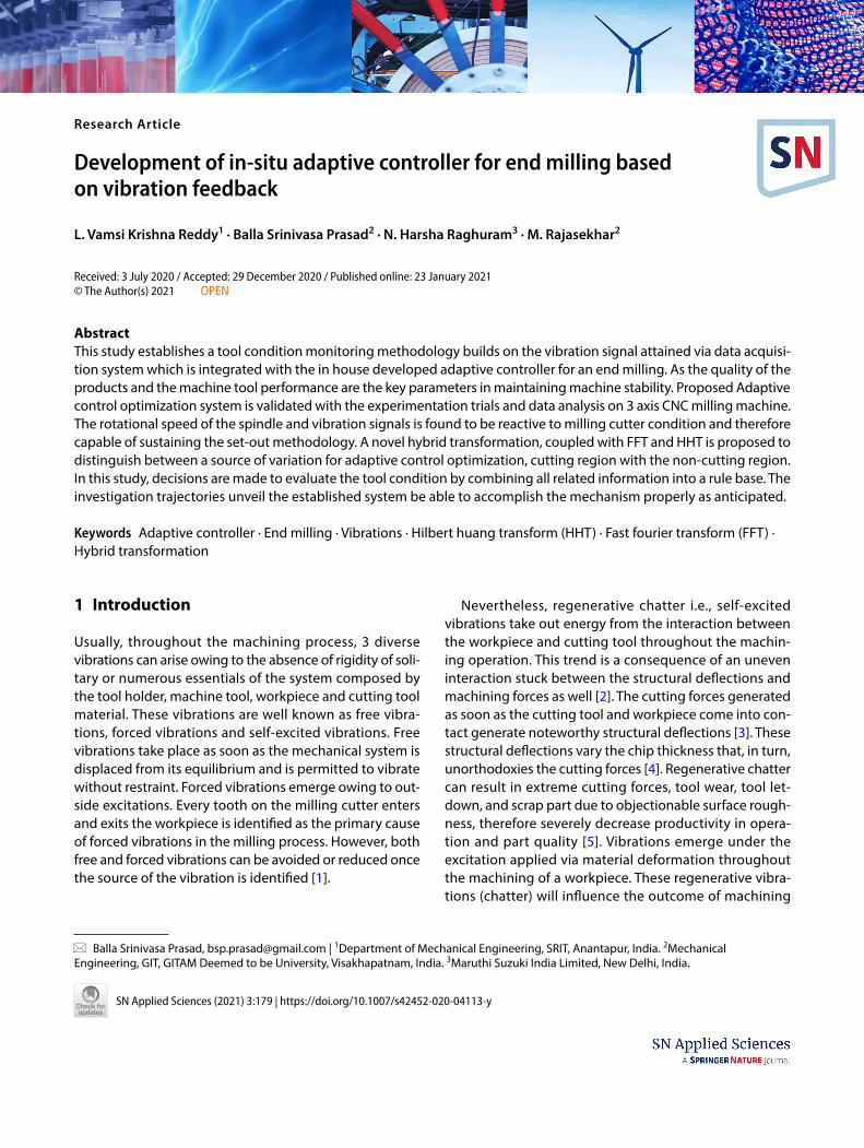
To develop the adaptive controller, it requires interfac-ing between the vibration sensor and SC06 CNC machine controller driver. An in house adaptive controller is devel-oped which is used to govern the NC machine controller (SC06) based on the vibration feedback received from the Kistler accelerometer. The configuration of the proposed design of the adaptive controller is presented in Fig. 1. The validation of the proposed controller for CNC end milling operation is carried out in-situ condition. Outcome of all the mentioned steps is an expected consequence of adap-tive controller implementation. All the stages explained with full details in Sect. 4.1.
The details of this adaptive controller will be enlight-ened in the next section. The part programmer develops an offline optimized set of speed, feed and depth of cut parameters for a particular machining operation (in this study, milling) and feeds the program into the GUI Inter-face. This interface networks with machining controller, translates the CNC commands into servo drive commands sequentially, and is executed chronologically.
3 Experiment design and equipment details
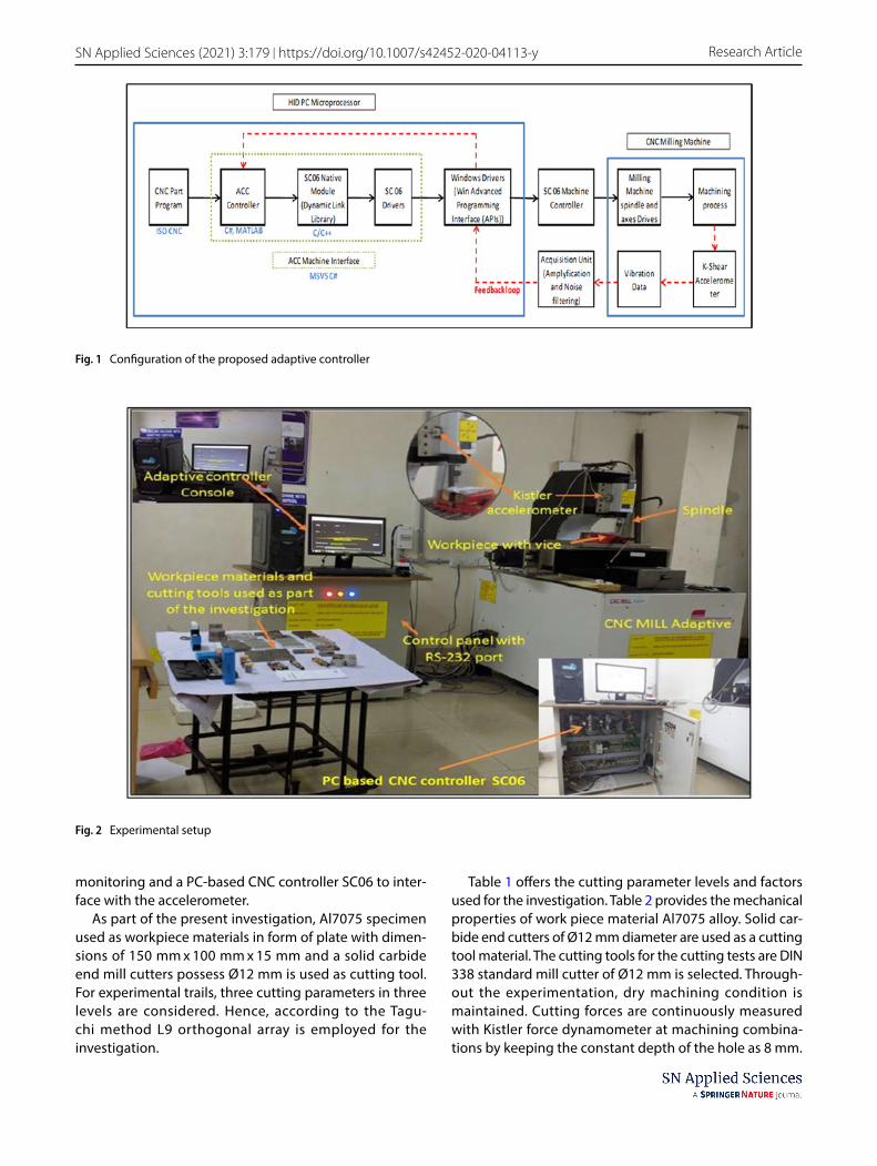
The investigational test set up in Fig. 2, comprising of a 3 axis CNC Milling machine possesses high-speed spindle, 3.5 KW spindle, rated at 18,000 RPM. Kistler 8793 acceler-ometer mounted on a spindle housing to enable vibration
Vol.:(0123456789)
SN Applied Sciences (2021) 3:179 | https://doi.org/10.1007/s42452-020-04113-y Research Article
monitoring and a PC-based CNC controller SC06 to inter-face with the accelerometer.
As part of the present investigation, Al7075 specimen used as workpiece materials in form of plate with dimen-sions of 150 mm x 100 mm x 15 mm and a solid carbide end mill cutters possess Ø12 mm is used as cutting tool. For experimental trails, three cutting parameters in three levels are considered. Hence, according to the Tagu-chi method L9 orthogonal array is employed for the investigation.
Table 1 offers the cutting parameter levels and factors used for the investigation. Table 2 provides the mechanical properties of work piece material Al7075 alloy. Solid car-bide end cutters of Ø12 mm diameter are used as a cutting tool material. The cutting tools for the cutting tests are DIN 338 standard mill cutter of Ø12 mm is selected. Through-out the experimentation, dry machining condition is maintained. Cutting forces are continuously measured with Kistler force dynamometer at machining combina-tions by keeping the constant depth of the hole as 8 mm.
Fig. 1 Configuration of the proposed adaptive controller
Fig. 2 Experimental setup
Vol:.(1234567890)
Research Article SN Applied Sciences (2021) 3:179 | https://doi.org/10.1007/s42452-020-04113-y
Work pieces are made to introduce certain wellspring of variation in cutting conditions like gaps (in this particular study). So cut plan is also designed in such a way that cut-ter comes in contact with workpiece for some time and does not cut some does not interact with the work piece in gaps.
4 Development of strategy for an in‑house adaptive controller
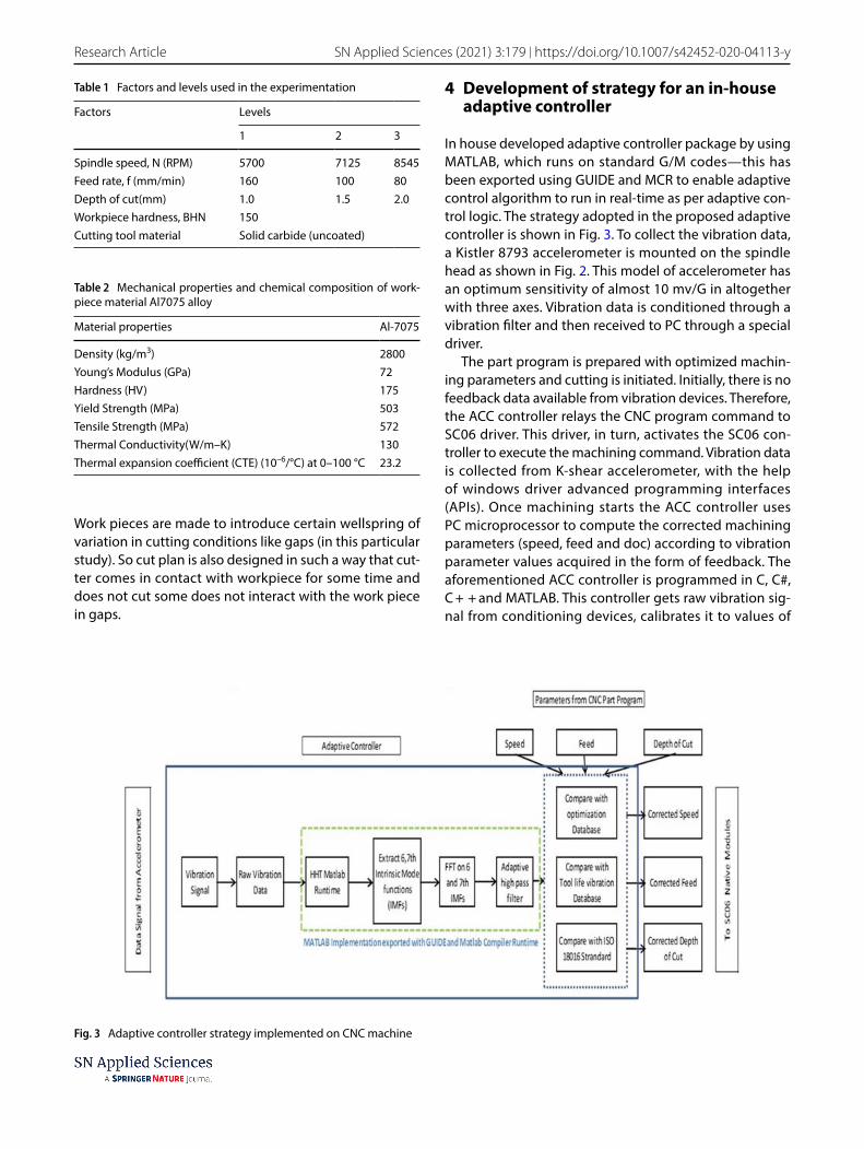
In house developed adaptive controller package by using MATLAB, which runs on standard G/M codes—this has been exported using GUIDE and MCR to enable adaptive control algorithm to run in real-time as per adaptive con-trol logic. The strategy adopted in the proposed adaptive controller is shown in Fig. 3. To collect the vibration data, a Kistler 8793 accelerometer is mounted on the spindle head as shown in Fig. 2. This model of accelerometer has an optimum sensitivity of almost 10 mv/G in altogether with three axes. Vibration data is conditioned through a vibration filter and then received to PC through a special driver.
The part program is prepared with optimized machin-ing parameters and cutting is initiated. Initially, there is no feedback data available from vibration devices. Therefore, the ACC controller relays the CNC program command to SC06 driver. This driver, in turn, activates the SC06 con-troller to execute the machining command. Vibration data is collected from K-shear accelerometer, with the help of windows driver advanced programming interfaces (APIs). Once machining starts the ACC controller uses PC microprocessor to compute the corrected machining parameters (speed, feed and doc) according to vibration parameter values acquired in the form of feedback. The aforementioned ACC controller is programmed in C, C#, C + + and MATLAB. This controller gets raw vibration sig-nal from conditioning devices, calibrates it to values of
Table 1 Factors and levels used in the experimentation
Factors Levels
1 2 3
Spindle speed, N (RPM) 5700 7125 8545Feed rate, f (mm/min) 160 100 80Depth of cut(mm) 1.0 1.5 2.0Workpiece hardness, BHN 150Cutting tool material Solid carbide (uncoated)
Table 2 Mechanical properties and chemical composition of work-piece material Al7075 alloy
Material properties Al-7075
Density (kg/m3) 2800Young’s Modulus (GPa) 72Hardness (HV) 175Yield Strength (MPa) 503Tensile Strength (MPa) 572Thermal Conductivity(W/m–K) 130Thermal expansion coefficient (CTE) (10–6/°C) at 0–100 °C 23.2
Fig. 3 Adaptive controller strategy implemented on CNC machine
Vol.:(0123456789)
SN Applied Sciences (2021) 3:179 | https://doi.org/10.1007/s42452-020-04113-y Research Article
acceleration unit based on Kistler data specification sheet. At present, the actual vibration data is fed into the pro-posed hybrid transformation, which is a combination of HHT and FFT [14]. The output from this stage is used in the decision of whether the individual machining parameters can be increased or decreased. Some threshold limits are also applied to decision-based on the result in accordance with ISO 10,186–3 standard [15]. Cheddadi et al. [16] dem-onstrated the design of an intelligent IoT enabled energy monitoring system and effectively implemented at pho-tovoltaic stations.
4.1 In‑situ implementation of an adaptive controller
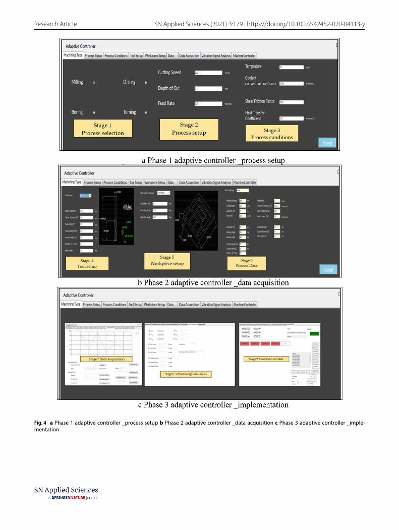
This section presents the various stages in the design and implementation of the adaptive controller based on vibra-tion feedback. Major stages of the controller design and implementation are pictorially represented in Fig. 4.
Figure 4a gives input phase of adaptive controller for specific machining application. In addition to milling, this controller logic can be applicable to drilling, turning and boring as well. But the results of this manuscript is lim-ited to milling operation only. Figure 4b presents the data acquisition phase whereas as Fig. 4c represents the signal conditioning followed by actual implementation of adap-tive controller strategy for milling. The part program is offline optimized by the part programmer, further relayed to ACC Controller on PC. The design of adaptive controller comprises of nine major stages as shown in Fig. 4. The first stage gives the option to make the selection regarding machining operation. Optimized machining parameters are fed to the SC06 controller in the second stage and required part program is generated to initiate the cutting process. Details of the process condition are entered into the controller in the third stage. The fourth stage gives the scope for selecting the required milling cutter from the tool’s database associated with the adaptive controller whereas the fifth stage allows us to choose the desired cutting plan. Stage 6 is the process data stage, where all the boundary conditions must be furnished. Stage 7 is a data acquisition module where the user is allowed to customize sample size data set, number of samples and average count etc.
In stage 8, signal analysis is carried out for acquired vibration data. This stage consists of threshold param-eters (machine and vibration safety) in FFT and hybrid Transformation or coupled FFT and HHT is represented as RRT. Final stage 9 gives the implementation phase of in house developed adaptive controller along with the part program in real-time.
4.2 Cut planning
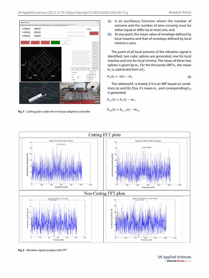
The actual cutting tool interactions with the work piece during the materials and slots are illustrated in Fig. 5. Ini-tially for analysis, a separate phase of the controller is also designed which takes inputs from CNC program, cut plan and present cutting parameters (rotational speed of the spindle, feed rate and depth of cut) to group vibration samples into cutting and non-cutting vibration data.
4.3 Modeling of proposed hybrid transformation (RRT)
According to the proposed Hybrid Transformation or cou-pled FFT and HHT, the acquired intrinsic mode functions (IMFs) from empirical mode decomposition (EMD) are converted into frequency spectrum by using Fast Fourier transformation (FFT).
For a vibration signal x(t) in the time domain, its fre-quency spectrum is defined as,
where, F0 =1
T is the fundamental frequency.
Ck is the kth Fourier series coefficient or kth harmonic coefficient.
ej2�kF0t = cos(2�kF0t) + j sin(2�kF0t) , is a complex sinusoid.
And,
Substituting Eq. 2 in Eq. 1, the complete frequency spectrum of x(t) can be represented as:
This Eq. (3) has been numerically computed using MAT-LAB for a discretized vibration signal and spectrum of cut-ting and non-cutting regions are shown in Fig. 6 (Cutting) and Fig. 6 (Non-Cutting). Also, instead of converting the whole vibration signal directly into the frequency spec-trum, Empirical mode decomposition (EMD) of the time domain signal is done as described in [17], to obtain Intrin-sic Mode Functions (IMFs). An IMF is defined by below two characteristics:
(1)x(t) =
∞∑
k=0
Ck ⋅ ej2�kF0t
(2)Ck =1
T
[
∫∞
−∞
x(t) ⋅ e−j2�kF0tdt
]
(3)X(F) =1
T
∞∑
−∞
[
∫∞
−∞
x(t)e−j2�kF0tdt
]
⋅ ej2�kF0t
Vol:.(1234567890)
Research Article SN Applied Sciences (2021) 3:179 | https://doi.org/10.1007/s42452-020-04113-y
Fig. 4 a Phase 1 adaptive controller _process setup b Phase 2 adaptive controller _data acquisition c Phase 3 adaptive controller _imple-mentation
Vol.:(0123456789)
SN Applied Sciences (2021) 3:179 | https://doi.org/10.1007/s42452-020-04113-y Research Article
(a) Is an oscillatory function where the number of extreme and the number of zero-crossing must be either equal or differ by at most one, and,
(b) At any point, the mean value of envelope defined by local maxima and that of envelope defined by local minima is zero.
The point of all local extreme of the vibration signal is identified, two cubic splines are generated, one for local maxima and one for local minima. The mean of these two splines is given by m1 . For the first proto-IMF h1 , the mean m1 is subtracted from x(t),
The obtained h1 is tested, if it is an IMF based on condi-tions (a) and (b), Else, it’s mean m11 and corresponding h11 is generated.
(4)h1(t) = x(t) −m1
h11(t) = h1(t) −m11
h1n(t) = hn−1(t) −m1nFig. 5 Cutting plan under the in-house adaptive controller
Fig. 6 Vibration signal analysis with FFT
Vol:.(1234567890)
Research Article SN Applied Sciences (2021) 3:179 | https://doi.org/10.1007/s42452-020-04113-y
This process is followed until a satisfactory h1n(t) is found to give I1(t) , the first IMF.
This process is continued until all IMFs are obtained from the vibration signal. Now instantaneous frequencies of the above IMFs are obtained through Hilbert transform:
The obtained analytical signal can be defined as follow:
where, In(t) represents nth IMF.
and
Instantaneous frequency can be directly obtained by
Equations (5–9) are numerically computed using MAT-LAB. The sample results are presented in Figs.6–8 with proper discussion. Still, characteristic differences are not observed. As already discussed, present study uses Hybrid Transformation or coupled FFT and HHT is represented as RRT, in which the obtained IMFs from Eqs. (4) and (5) is transformed into the frequency domain using Fourier series, as,
where In(t) represents nth IMF.Then XIn
(F) spectrum is subjected to a filter R(F) , which is as defined as follow,
where fn is a natural frequency of the CNC machining system used for the experiment.
In the present study, specific to the procured machine and signal conditioning system, fn = 5 Hz is found to be most useful. The RRT spectrums for all IMFs, viz.,
(5)I1(t) = h1n(t)
(6)H(In(t)) =1
�PV ∫
∞
−∞
In(�)
t − (�)d�
�y
�x
(7)aIn = x(t) + jy(t) = r(t)ej�(t)
(8)r(t) =√
x2 + y2
(9)θ(t) = tan−1y
x
(10)fi =d�
dt
(11)XIn (F) =1
T
∞∑
−∞
[
∫∞
−∞
In(t)e−j2�kF0tdt
]
⋅ ej2�kF0t
(12)R(F) =
{
F∀F > fn0∀F ≤ fn
R[
XI1(F)
]
, R[
XI2(F)
]
, … . R[
XIn(F)
]
are generated numerically and it is found that R
[
XI6(F)
]
is the most useful spectrum [18], the results are illustrated in Fig. 9 in Sect. 5.
5 Results and discussions
Several experiments were conducted with a different set of workpieces and tool material combinations. The grouped data obtained from the controller is analyzed with various techniques to distinguish between cutting (without air gap) and non-cutting (air gap) time. Initially, FFT analysis is carried out to find out the maximum fre-quency and maximum amplitude but they found to be continuously varying and no characteristic inferences could be drawn.
Figure 6 gives the acceleration amplitude in the fre-quency domain. This is also the case with Hilbert spectral plots shown in Fig. 7. In Fig. 7, no inference is observed with regard to tool and work piece interaction and no fre-quency density with respect to time can also be found in any region irrespective of cutting.
After numerous experiments, the present study tried to use Hilbert-Huang transformation [19], for non-station-ary and non-linear vibration. Figure 8 gives the empirical mode decomposition of the vibration signal i.e., IMFs for both cutting (without air gap) and no- cutting (air gap).
As shown in Fig. 8, it is identified that on empirical mode decomposition of the acquired data signal, the IMFs of the order greater than 4 [20], i.e., IMFs 5, 6, 7 showed some characteristic variation with respect to the tool vibra-tions when it is actually involved in cutting and during air gap. In the present study, IMF 6 is found to be the most useful component for differentiating whether the tool is actually cutting or not. In simpler terms [21], the IMF6 is found to be possessing higher harmonics in case of cut-ting and lower harmonics in case of air gap operation (i.e., non-cutting region) as shown in Fig. 8. But these harmon-ics could not be quantified with HHT.
To overcome this, a hybrid transformation is proposed which is a combination of HHT and FFT. This hybrid trans-formation is termed as RRT. According to the proposed transformation (RRT), the acquired intrinsic mode func-tions (IMFs) from empirical mode decomposition (EMD) are converted into a frequency spectrum by Fast Fourier transformation [22]. Later, obtained spectral values are passed through a threshold filter that cuts of frequencies having amplitude < 0.5 mm/sec2 and only the frequencies of interest are analyzed and they are presented in Fig. 9.
Vol.:(0123456789)
SN Applied Sciences (2021) 3:179 | https://doi.org/10.1007/s42452-020-04113-y Research Article
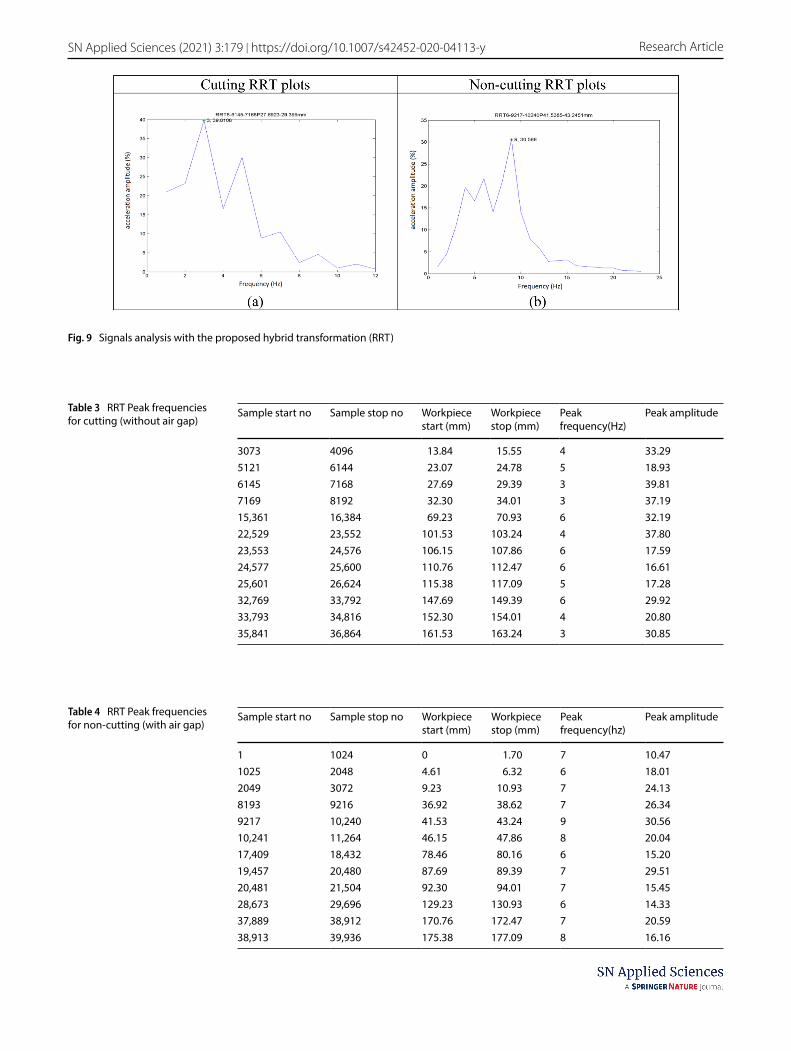
RRT analysis plots shown in Fig. 9 represent the 2 cases. Figure 9a indicates the cutting condition and Fig. 9b rep-resents the air gap condition. It is identified that when cut-ting process is carried out the peaks of the RRT plot are typically in the range of 1–5 Hz and while passing through the air gap the peaks of the plot shifted to higher frequen-cies i.e., 7–10 Hz. To confirm the same fact, the new 3,162 datasets RRT plots for IMF6 and IMF7 are generated. The peak values in each plot are calculated, their frequency of occurrence. Table 3 gives the RRT Peak frequencies for while cutting whereas Table 4 presents the RRT Peak fre-quencies for non-cutting i.e. when the air gap is present.
These results are implemented and validated on the core of the adaptive controller in Fig. 1 in real-time. Based on the RRT result, the adaptive controller identifies the cut-ting tool and workpiece interactions. Once identified, there are a set of feed rate/rotational speed steps that can be defined, for which the ACO will make a decision whether to step up or step down the machining parameters. If any
vibration sample’s RRT peak results in 9 Hz, then adaptive controller checks if the feed rate can be optimized or not. For example, if the present table feed rate is 120 mm/min and the predefined steps allow a feed rate up-gradation to 240 mm/sec, subsequently in-house adaptive control-ler overrides the part program feed rate. This enables to decrease the production time and thereby cost.
6 Conclusions
An in-house adaptive controller has been designed based on vibration data. To facilitate the data acquisition in real-time, integration is established between programmable PC-based CNC controller Interface SC06 with a vibration signals transducer Kistler 8793 K-Shear Tri-Axial accelerom-eter through MATLAB program routine to work under the designed controller. In the present study, a hybrid novel approach proposed which is a combination of HHT and
Fig. 7 Vibration signal analysis with Hilbert Transform
Vol:.(1234567890)
Research Article SN Applied Sciences (2021) 3:179 | https://doi.org/10.1007/s42452-020-04113-y
FFT and implemented successfully in real-time for end milling operation. It is also found that proposed RRT trans-formation is more effective for identifying the variations in tool-workpiece interactions such as air gaps while cutting.
This adaptive controller controls the milling process parameters in real-time and maintains vibration under a preset safety threshold value by means of driver interfac-ing for adaptation of machining parameters. Applicabil-ity of the method for the adaptive alteration of milling
parameters is demonstrated and tested on a 3-axis CNC milling machine with experimental trails [23]. Results of the end milling experiments with adaptive controller strat-egy display that the established in house controller has great sturdiness and steadiness.
The complexity of the transforms integration may be reduced with advanced software even at the acquisition of the signal as part of the future study.
Fig. 8 Empirical mode decomposition of the vibration signal i.e., IMFs for both cutting (without air gap) and non-cutting (air gap)
Vol.:(0123456789)
SN Applied Sciences (2021) 3:179 | https://doi.org/10.1007/s42452-020-04113-y Research Article
Fig. 9 Signals analysis with the proposed hybrid transformation (RRT)
Table 3 RRT Peak frequencies for cutting (without air gap)
Sample start no Sample stop no Workpiece start (mm)
Research Article SN Applied Sciences (2021) 3:179 | https://doi.org/10.1007/s42452-020-04113-y
Acknowledgements Science and Engineering Research Board (SERB), Department of Science and Technology (DST), Ministry of Science and Technology, Govt. of India fund this research work with sanction No. SB/FTP/ETA-0262/2013.
Compliance with ethical standards
Conflict of interest Authors confirm that there is ‘No conflict of inter-est’.
Open Access This article is licensed under a Creative Commons Attri-bution 4.0 International License, which permits use, sharing, adap-tation, distribution and reproduction in any medium or format, as long as you give appropriate credit to the original author(s) and the source, provide a link to the Creative Commons licence, and indicate if changes were made. The images or other third party material in this article are included in the article’s Creative Commons licence, unless indicated otherwise in a credit line to the material. If material is not included in the article’s Creative Commons licence and your intended use is not permitted by statutory regulation or exceeds the permitted use, you will need to obtain permission directly from the copyright holder. To view a copy of this licence, visit http://creat iveco mmons .org/licen ses/by/4.0/.
References
1. Altintas Y (2012) Manufacturing automation: metal cutting mechanics machine tool vibrations and CNC design, 2nd edn. Cambridge University Press, Cambridge, pp 125–190. https ://doi.org/10.1017/CBO97 80511 84372 3.006
2. Quintana G, Ciurana J (2011) Chatter in machining processes: a review. Int J Mach Tools Manuf 51(5):363–376
3. Budak E (2006) Analytical models for high performance mill-ing Part I cutting forces structural deformations and tolerance integrity. Int J Mach Tools Manuf 46(12–13):1478–1488
4. Toh CK (2004) Vibration analysis in high speed rough and finish milling hardened steel. J Sound Vib 278(1–2):101–115
5. Munoa J, Beudaert X, Dombovari Z, Altintas Y, Budak E, Brecher C, Stepan G (2016) Chatter suppression techniques in metal cut-ting. CIRP Ann 65(2):785–808
6. Wiercigroch M, Budak E (2001) Sources of nonlinearities chat-ter generation and suppression in metal cutting. Philosophi-cal Transactions Royal Soc London Series Math Phys Eng Sci 359(1781):663–693
7. Zuperl U, Cus F, Kiker E, Milfelner M (2005) A combined system for off-line optimization and adaptive adjustment of the cutting parameters during a ball-end milling process. Strojniski Vestnik 51(9):542–559
8. Cus F, MilfelnerBalic MJ (2006) An intelligent system for monitor-ing and optimization of ball-end milling process. J Mater Process Technol 175(1–3):90–97
9. Prickett PW, Siddiqui RA, Grosvenor RI (2011) A microcontroller-based end milling cutter monitoring and management system. The Int J Adv Manuf Technol 55(9–12):855–867
10. Jardine AK, Lin D, Banjevic D (2006) A review on machinery diagnostics and prognostics implementing condition-based maintenance. Mech syst signal process 20(7):1483–1510
11. Tong X, Liu Q, Pi S, Xiao Y (2019) Real-time machining data application and service based on IMT digital twin. J Intell Manuf 31:1–20
12. Bort CMG, Leonesio M, Bosetti P (2016) A model-based adap-tive controller for chatter mitigation and productivity enhance-ment in CNC milling machines. Robotics Comput-Integr Manuf 40:34–43
13. Coppel R, Abellan-Nebot JV, Siller HR, Rodriguez CA, Guedea F (2016) Adaptive control optimization in micro-milling of hard-ened steels evaluation of optimization approaches. Int J Adv Manuf Technol 84(9–12):2219–2238
14. Marques JR, Machado IF, Cardoso JR, Barbosa PA (2014) The use of the Hilbert-Huang transform in the analysis of machining vibrations in machine tools. In: IECON 2014–40th annual con-ference of the IEEE industrial electronics society IEEE:3494–3500
15. Prasad BS, Prasad DS, Sandeep A, Veeraiah G (2013) Condition monitoring of CNC machining using adaptive control. Int J Autom Comput 10(3):202–209
16. Cheddadi Y, Cheddadi H, Cheddadi F, Errahimi F, Es sbai N (2020) Design and implementation of an intelligent low cost IoT solu-tion for energy monitoring of photovoltaic stations. SN Appl Sci 2:1165
17. Bellman RE (2015) Adaptive control processes: a guided tour. Princeton University Press, Princeton, NJ, pp 194–201
18. Landau ID, Lozano R, M’Saad M, Karimi A (2011) Adaptive con-trol: algorithms, analysis and applications. Springer, New york
19. Huang NE, Shen SSP (2014) Hilbert-Huang transform and its applications, vol 16, 2nd edn. World Scientific Publishing Com-pany, pp 1–16
20. Kalvoda T, Hwang YR (2010) A cutter tool monitoring in machin-ing process using Hilbert-Huang transform. Int J Mach Tools Manuf 50(5):495–501
21. Susanto A, Liu CH, Yamada K, Hwang YR, Tanaka R, Sekiya K (2018) Milling process monitoring based on vibration analy-sis using hilbert-huang transform. Int J Automation Technol 12(5):688–698
22. Wei CC, Liu MK, Huang GH (2016) Chatter identification of face milling operation via time-frequency and Fourier analysis. Int J Automation Smart Technol 6(1):25–36
23. Mouli KVVNRC, Prasad BS, Sridhar AV, Alanka S (2020) A review on multi sensor data fusion technique in CNC machining of tailor-made nanocomposites. SN Appl Sci 2:1–12
Publisher’s Note Springer Nature remains neutral with regard to jurisdictional claims in published maps and institutional affiliations.