31


2 I s s u e n o . 2 8 4 S e p t e m b e r 2 0 0 7
DEVELOPMENT OF INNOVATIVE PROCESSES FORTHE SEPARATION OF HIGH PURITY URANIUM
FROM PHOSPHORIC ACID
Harvinderpal SinghRare Earths Development Section
Phosphoric acid is processed in large volumes by Indianindustries, into fertilizers and detergent phosphates. Amajor proportion of this acid contains uranium insignificant concentration. Phosphates have long beenrecognized to be an important secondary source ofuranium and indigenous development of processes ofseparation, has been an important area of R&D at BARC[1]. The key step in the separation flowsheet is solventextraction. In India, the major proportion of phosphoricacid is in the concentrated form, generally called the‘Merchant Grade’ Acid (MGA). The phosphate contentof MGA, expressed as P2O5 weight percentage is ~ 55.Typical analysis is given in Table 1. Viscosity of MGA ishigh, in the range of 20-50 centipoise. Depending onthe nature of phosphoric acid, a particular type of solventis needed. BARC has recently developed a novel solventextraction process based on Di-Nonyl Phenyl PhosphoricAcid (DNPPA) which has been patented [2]. Anotherprocess has been developed and patented using currentlyavailable indigenous industrial solvents for extraction from~28% P2O5 weak acid (WPA) [3]. The salient details ofthese two processes are described in this paper, aftergiving a general description of the overall separationflow sheet. Some recent R&D work is summarized inthe concluding part of the paper. More details areavailable in the published references [4-9].
Process Flow sheet for Uranium Separation fromPhosphoric Acid
The overall flowsheet for separation of uranium fromWPA or MGA is schematically shown in Fig. 1. It involvesfour types of operations, which can be described as
pre-treatment, solvent extraction, ‘yellow cake’ recoveryand post-treatment.
Pre-treatment of phosphoric acid involves cooling ofthe acid as a first step. The efficiency of separationis improved as a result of cooling since the subsequentsolvent extraction is an exothermic equilibrium process.The phosphoric acid as produced in industriesis often hot. Hence cooling to a temperature of ~30oCis carried out. A flash cooling system with highrecycle ratio is preferred, since solids are presentin the phosphoric acid. Solids are generated asa result of cooling, since the lowering oftemperature results in supersaturation of the aqueousphase, with reference to many dissolved salts
Table 1: Typical analysis of concentrated‘merchant grade’ phosphoric acid (MGA)

3I s s u e n o . 2 8 4 S e p t e m b e r 2 0 0 7
Fig. 1: Overall flowsheet for uranium separation from phosphoric acid

4 I s s u e n o . 2 8 4 S e p t e m b e r 2 0 0 7
[10]. For smaller duties, spiral coolers can be used. Thenext step in pre-treatment is separation of suspendedsolids. This is achieved by clariflocculation with highmolecular weight polymeric flocculants. Severalindigenously produced flocculants have been successfullytested and product acid with <300 ppm solids wasobtained, in both lab-scale and pilot-scale tests. Ourstudies show, that polymeric flocculants also serve toseparate a significant amount of humic material fromthe acid. While gravity clari-flocculators are suitable forweak acid, concentrated MGA needs amplification ofthe gravity force in machines, such as solid bowlcentrifuges. The concentrated acid is far more viscousthan weaker acid and hence solid-liquid separationbecomes more difficult. Separation of solids serves toensure trouble-free down-stream operations of carbontreatment and solvent extraction. Solid separation byfiltration is difficult to achieve for the viscous MGA andalthough it is feasible for weaker acid, it is industriallyan expensive option. The third step of pre-treatment,after cooling and solid separation, is separation of thecontained humic matter. Phosphoric acid produced fromnaturally occurring rocks, invariably contains humicmatter, that can interfere with the solvent extraction.Hence, this separation is essential. It is most efficientlyachieved by adsorption of humic material on activatedcarbon, used in the form of granules that have beenpacked into a series of columns. A view of such a facilityis shown in Fig. 2. Pilot plant continuous test-work hasbeen carried out, both with weak and concentratedphosphoric acids. Various grades of indigenous carbonshave been tested and in particular the material preparedfrom coconut shells has been found to be eminentlysuitable. In fact, such carbons are exported from India.Tests have shown that performance of Indian carbons issuperior to that of imported materials. Several cycles ofcolumn adsorption, washing and re-generation withNaOH solution have been carried out. The acid obtainedfrom activated carbon pre-treatment, is a green acid. Acheaper option to activated carbon, involves the use ofactivated clays. We have evaluated a number ofindigenous clays in once-through mode based onfiltration. Depending on specific local conditions in a
host plant, this option can be feasible. The clean greenacid is subjected to the next step of pre-treatment, thatinvolves oxidation with air or gaseous oxygen, followedby finishing with aqueous hydrogen peroxide. This stepof oxidation serves to convert all the uranium fromtetravalent to hexavalent state, the form which isnecessary for the two innovative processes as given inthe patents.
Solvent extraction of uranium from phosphoric acid bythe two processes, has several features in common, thatare described herein. An important feature is the conceptof a dual cycle flowsheet. In the first cycle, uranium isfirst extracted and then stripped into a small stream ofconcentrated acid. As a result of this first cycle operation,uranium concentration increases by a factor of 50-100.This cycle is optimized for high recovery with as fewstages of contacting as technically needed, in order toreduce plant inventory and lower capital and operatingcosts. A common feature of the two patented processes,
Fig. 2: Photograph of carbon columns forpre-treatment

5I s s u e n o . 2 8 4 S e p t e m b e r 2 0 0 7
is the use of MGA as stripping agent at 55-600Cunder reducing conditions, achieved by the usingmetallic iron. Both conditions of raising the temperatureand use of MGA (instead of weak acid) aid in efficiencyof operation. In the second cycle of solvent extraction,the purity of uranium with respect to co-extractedimpurities such as iron, rare earths and phosphate isachieved, by incorporating a set of scrubbing stages inthe flowsheet. For both the patented processes, selectionof a suitable scrubbing medium is a key feature of theinnovation. In addition to this, the outlet scrub streamprovides a potential source of by-products such as rareearths. In the second cycle, the medium used for strippingof purified uranium extract is alkaline solution ofammonium or sodium carbonate. The uranium bearingaqueous alkaline solution is further processed byprecipitation of uranyl peroxide. The peroxide precipitationis a common feature of the two patented processes thatyields a ‘yellow cake’ which is far superior to theMagnesium Diuranate (MDU) industrially produced fordecades in the country. A view of samples of uraniumperoxide from phosphates, diuranates and trioxideobtained from the peroxide is shown in Fig. 3.
The barren phosphoric acid from the solvent extractionbattery is returned to the mother phosphate industryafter ‘post-treatment’. This involves separation of tracesof solvent from the aqueous phase, with the twinobjectives of: a) Solvent recovery for techno-economicoperation and b) ensuring the return acid does not containany contaminants that can interfere with the subsequentacid processing in the host industry. This step of post–treatment is carried out in a series of equipmentconsisting of lamellar coalescer, dissolved air floatation,counter-current diluent washing and activated carbonadsorption. The final acid is pre-heated before return, ifrequired by the host plant. Similarly the solids that hadbeen separated as a part of pre-treatment, are mixedwith return acid, if needed by host plant, to ensuredownstream operation of production of fertilizer granulesis unaffected.
Fig. 3: Photograph of yellow cake
Next the specific innovative details of the two processes,which have been developed to meet two differentindigenous requirements are described.
DNPPA-TOPO Solvent Extraction Process foruranium recovery from MGA.
This process was developed specifically in the context ofindigenous industry, which uses concentrated acid(MGA) from various sources in large volumes. In fact,the largest phosphatic plants in the country use MGA asthe source material rather than the weaker acid. Evenplants that rely on weak acid as source material, havethe option of switching over to purchased MGA in theevent of non-availability of weak acid. Large volumes ofthe MGA handled in the industry enable economy ofscale. An additional conclusion derived from the datacollected by BARC is that, MGA sources are richer in
Ammonium Di Uranate(Room Temp)
Uranium Peroxide(Room Temp)
Uranium Peroxide(180o C)
Uranium Peroxide(200o C)
Uranium Peroxide (400o C)

6 I s s u e n o . 2 8 4 S e p t e m b e r 2 0 0 7
uranium content, on an average, as compared to weakeracid – even when comparison is based on U/P ratiorather than concentration in ppm. The reason for this,lies in the observed higher uranium content of the rocksused for MGA, than those used for WPA.
A survey of the literature revealed that world-wideuranium recovery has been attempted only from theweaker phosphoric acid, in view of the difficulty ofextraction, which is in turn related to the complexationof ionic species of uranium into less extractable form, asthe acidity increases. Limited studies that have beenreported [11] on the separation of uranium fromconcentrated acid, have involved the extraction oftetravalent uranium by a mixture of mono-ester and di-ester forms of phenyl phosphoric acid. Such processessuffer from the disadvantages that considerable amountof other impurities such as iron and rare earths areco-extracted, the stripping of uranium involves corrosiveacids such as HF, the solvent system is unstable andoverall recovery uneconomic. In fact, an earlier studyfrom BARC had reported results in this direction [12]which in itself was a significant scientific advance, thatphenyl phosphoric acids could be used as feasibleextractants.
The inventive work covered by our patented processes,adopted a different approach, based on extraction ofhexavalent uranium by a synergistic mixture of acidicorgano-phosphorus compound, with a neutral synergistmolecule. Such a system enables reductive stripping,adoption of dual cycle approach which yields high purityuranium, leads to minimum contamination of phosphoricacid as is desired by host fertilizer plant, avoids corrosivechemicals and has the flexibility of being integrated intoa host plant, handling both weak and concentratedphosphoric acids.
In order to meet the above objective, the solvent usedhad to be of high purity, another point of departurefrom earlier work in this field, at BARC. Based onaccumulated experience and literature survey, DNPPA wasselected as the acidic extractant and TOPO as the
synergist. Since DNPPA is not commercially available, itwas synthesized by us in the laboratory. A mixture ofdi– and mono-esters of nonylphenyl phosphoric acidwas obtained by reacting p-nonyl phenol withphosphorous oxy-chloride in the presence of pyridine inthe mole ratio of 2:1:2. The reaction mixture washydrolyzed with excess of 6 M HCl at 80oC for 12 h.The di-ester and mono-ester were separated by extractionfrom benzene solution with 70% methanol. Theunreacted nonyl phenol and neutral compounds, wereseparated by loading the benzene layer with neodymium(Nd) and precipitating the Nd-diester salt, in excessacetone. Di-ester was obtained by dissolving the salt inbenzene and stripping with oxalic acid. Theconcentrations of mono-and di-esters were determinedby potentiometric titration with alkali in ethanolmedium. Pure DNPPA was found to be a pale yellowliquid with a density of 1.03, refractive index of 1.513,having acid number of 105.53 and molecular weight of502.
The extraction ability of the solvent thus obtained wasevaluated by contacting with synthetic phosphoric acidspiked with uranium. As shown in Table 2, the synergisticphenomenon is established by the fact, that the extractionpower (measured by the distribution ratio D which isthe ratio of equilibrium concentrations of uranium inthe extracted organic phase to the aqueous phase) forthe mixture is higher than that of DNPPA or TOPO alone.Next, the comparison of using DNPPA instead of D2EHPAwhich is conventional in weak acid extractions is shownin Table 3. The extraction power is increased 3-4 timeswhen DNPPA replaces D2EHPA in the organic phase.This conclusion is based on molar comparison.Recognizing the higher molecular weight of DNPPA thanthat of D2EHPA, results are different when comparisonis on the basis of weight. Next, the mole ratio of DNPPAto TOPO in the organic phase was varied and it wasfound that the optimum mole ratio is [DNPPA]/[TOPO]= 2:1 as against the optimum ratio of 4:1 for the D2EHPA– TOPO mixture. This shows that the nature of extractedspecies is different and there is no a prior rule foroptimization. Next, at constant mole ratio, the DNPPA

7I s s u e n o . 2 8 4 S e p t e m b e r 2 0 0 7
concentration was varied. Results are shown in Table 4.The increase in D value is found to follow a power lawwith an exponent of 0.6. It may be noted that DNPPA isa highly viscous extractant and the minimum necessaryconcentration in a diluent, is to be used. A furthercomparison of extraction of U-VI by 0.6 DNPPA + 0.3 MTOPO, with that of U-IV by 0.1 M DNPPA + 0.1 MMNPPA, showed comparable efficacy of separation,without the disadvantages associated with the extractionof tetravalent uranium, as discussed earlier.
Table 2: Extraction synergism for DNPPA-TOPO process
Table 3: Comparative extraction behaviour ofDNPPA and D2EHPA
Table 4: Effect of DNPPA concentration on extraction
(D=Distribution ratio)
Encouraged by the results of single-stage equilibriumextraction, tests were carried out in counter-current stagesat aqueous to organic phase ratio of 1.5 and over 90%extraction of uranium was obtained in eight stages ofseparation. Next the reductive stripping was carried outusing 12M H3PO4 with 10 g Fe2+/L at organic to aqueousratio of 20 and temperature of 600C. In five counter-current stages, with a loaded organic feed of0.11g U308/L, a pregnant aqueous solution containing> 2g U308/L was obtained.
The strip solution collected in the first cycle was used asfeed, after dilution and oxidation of uranium, for asecond cycle. The extractant used in the second cyclewas 0.3 M D2EHPA + 0.075 M TOPO. However, thephase ratio was increased in view of the dilute feed andthe extract was scrubbed with dilute sulfuric acid. Fromthe loaded organic phase, uranium was stripped with1 M ammonium carbonate solution. The strip solutionwas filtered to remove traces of iron precipitate. Theuranyl tri-carbonate solution contained excessammonium carbonate and pH was found to be8.3. Uranium precipitation was carried out using asolution of 40% H2O2. The neutralization was carriedout with sulfuric acid. In a pH range of 3-4, the uraniumprecipitation was complete (>99%). The pale yellowuranium peroxide (UO4.xH2O) was filtered, washed,dried and calcined to obtain black UO3 powder of>99% purity. Thus the entire process was proven.
An important feature of the solvent for industrial use
involves stability of the solvent. In order to establish
this, the solvent was contacted with feed acid for
15 days. After this period, the extraction behaviour was
compared with that of freshly prepared solvent and found
identical. Similarly cyclic stability tests were conducted.
These involved repeated extraction and stripping. Both
the composition and the phase separation behaviour were
studied. It was found, that over 50 cycles could be carried
out without any significant change. It was also found
that low monoester content of <1% was important
for stability.

8 I s s u e n o . 2 8 4 S e p t e m b e r 2 0 0 7
The studies were also carried out using other synergisticreagents such as di-butyl butyl phosphonate (DBBP) andlower concentraction of extractants when contacting withweak phosphoric acid. In all cases satisfactory extractionwith DNPPA based systems was achieved which wassuperior to the D2EHPA based extractants.
D2EHPA – TBP Solvent Extraction Process for WeakPhosphoric Acid
While the technical superiority of the DNPPA-TOPOprocess is established, its large scale industrial applicationis constrained by the non-availability of both thecomponents in tonnage scale. Thus industrial exploitationof technology is presently limited to weaker phosphoricacid for which D2EHPA is adequate and BARC has provedthe know how for its indigenous manufacture. But inthis case difficulties were encountered in the availabilityof TOPO and an indigenous option was urgently needed.Hence, we developed an alternate process based onindigenously available solvents D2EHPA and TBP in ashort span of less than one year.
A literature search revealed, thatvery limited work on theD2EHPA-TBP for uraniumextraction from phosphoric acid,had been carried out. The onlyprocess reported [13] involvedthe use of HF for stripping andresulted in a crude uraniumproduct that was contaminatedwith rare earths. Besides, therewere several inconsistencies inthe data. Hence, systematicparallel investigations werecarried out by us incorporatinginnovative approaches toovercome the limitations ofknown processes. In particular itwas found, that a suitablescrubbing stage in second cycleof two-cycle process, coupled
with uranyl peroxide precipitation, yielded a product ofhigh purity. The process was tested at several labs aswell as pilot plant tests were carried out, using freshlyproduced phosphoric acid at industrial sites in thecountry. Composition of various acids is given inTable 5.
The synergism between the extraction of uranium byD2EHPA and by TBP is weaker than that of D2EHPA andTOPO. However it is significant as shown by the resultsgiven in Table 6. This significant increase translates intoa very significant increase in recovery, when the effect ismultiplied in a counter-current cascade. This was verifiedon a number of phosphoric acids and results are givenin the patent.
It is shown that depending on the feed acidcharacteristics, over 90% uranium can be extracted in6-8 stages operating at ~30oC using 1.5 M D2EHPA +0.2 M TBP. The extraction is to be applied for weakphosphoric acid only, since as shown by the data givenin Table 7, the extraction power sharply decreases
Table 5: Analysis of weak phosphoric acids (WPA)

9I s s u e n o . 2 8 4 S e p t e m b e r 2 0 0 7
with the acid concentration. The behaviour of rareearths, which are present in the phosphoric acid inconcentrations often higher than uranium, is equallyimportant. With yttrium, as a representative element,the behaviour is shown in Table 8. This data also showsthat using concentrated phosphoric acid in thesubsequent stripping operation, both uranium and rareearths should get transferred from the organic phase tothe aqueous phase. In the first cycle of operation, thisensures that there is no build-up of these elements inthe recycled organic. However in the second cycle, theseparation of co-extracted uranium and rare earths intotwo different streams is desirable for product purity. Thisseparation is achieved by scrubbing. Sulphuric acid is avery suitable scrubbing agent in the environment of aphosphatic fertilizer plant. Using this agent, the effectof acid concentration is shown in Table 9. Thus efficientscrubbing is feasible by adjusting the aqueous acidity.
Table 6: Extraction synergism for D2EHPA-TBP process
Table 7: Effect of aqueous acidity onU extraction by D2EHPA-TBP
Table 8: Effect of aqueous acidity on yttrium extraction
Table 9: Effect of aqueousscrubbing acidity on Y
The precipitation of uranium after the process ofdual cycle extraction, is illustrated by the experimentaldata described hereinafter, for a typical fertilizer acid.Five litres of the combined solution resulting fromalkaline carbonate strip of second cycle, containing22.01 g/l uranium, was mixed at room temperatureof 29oC with 0.4 l of 12.5 M NaOH solution.This raised the pH to 12 and precipitated sodiumdiuranate. The precipitate was filtered and slurried
10 I s s u e n o . 2 8 4 S e p t e m b e r 2 0 0 7
in one litre of water and then 250 ml of 4 M sulfuricacid was added to it and the precipitate was dissolved.The insolubles were filtered out and the pH of the clearfiltrate solution was adjusted to 3.5 using 80 ml of12.5 M NaOH. After pH adjustment, 100 ml of H2O2
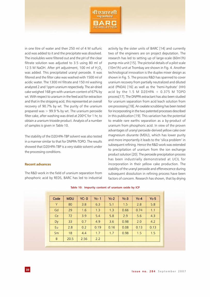
was added. This precipitated uranyl peroxide. It wasfiltered and the filter cake was washed with 1500 ml ofacidic water. The 1300 ml filtrate and 150 ml washinganalyzed 2 and 1ppm uranium respectively. The air-driedcake weighed 168 gm with uranium content of 67% bywt. With respect to uranium in the feed acid for extractionand that in the stripping acid, this represented an overallrecovery of 90.7% by wt. The purity of the uraniumprepared was > 99.9 % by wt. The uranium peroxidefilter cake, after washing was dried at 200oC for 1 hr, toobtain a uranium trioxide product. Analysis of a numberof samples is given in Table 10.
The stability of the D2EHPA-TBP solvent was also tested
in a manner similar to that for DNPPA-TOPO. The results
showed that D2EHPA-TBP is a very stable solvent under
the processing conditions.
Recent advances
The R&D work in the field of uranium separation fromphosphoric acid by REDS, BARC has led to industrial
activity by the sister units of BARC [14] and currentlytwo of the engineers are on project deputation. Theresearch has led to setting up of large-scale (60m3/h)pump-mix unit [15]. The pictorial details of a pilot scale(10m3/h) unit at Trombay are shown in Fig. 4. Anothertechnological innovation is the duplex mixer design asshown in Fig. 5. The process R&D has spanned to coveruranium recovery from partially neutralized and dilutedacid (PNDA) [16] as well as the ‘hemi-hydrate’ (HH)acid by the 1.5 M D2EHPA + 0.375 M TOPOprocess[17]. The DNPPA extractant has also been studiedfor uranium separation from acid leach solution fromore processing [18]. An oxalate scrubbing has been testedfor incorporating in the two patented processes describedin this publication [19]. This variation has the potentialto enable rare earths separation as a by-product ofuranium from phosphoric acid. In view of the provenadvantages of uranyl peroxide-derived yellow cake overmagnesium diurante (MDU), which has lower purityand more importantly it leads to the ‘silica problem’ insubsequent refining. Hence the R&D work was extendedto precipitation of uranium from the ion exchangeproduct solution [20]. The peroxide precipitation processhas been industrially demonstrated at UCIL forincorporation in their yellow cake production. Thestability of the uranyl peroxide and effervescence duringsubsequent dissolution in refining process have beenfactors of concern. Research has shown, that by drying
Table 10: Impurity content of uranium oxide by ICP

11I s s u e n o . 2 8 4 S e p t e m b e r 2 0 0 7
part of Plan projects, include R&D related to dissolvedand entrained solvent recovery as well as rare earthsby-product recovery. Rare earth elements such as Dy2O3
are of interest in nuclear reactors such as AHWR whilegadolinium oxide is used in PHWRs.
Fig. 6: Conversion of unstable uranylperoxide to stable trioxide
by drying
the uranyl peroxide at a suitable temperature and heatingrate, stable UO3 is obtained. This is illustrated by thedata of Fig. 6. The oxide product is a very stable pureform of uranium obtained from the secondary phosphaticsources. The data on these and related aspects has beencompiled [21-23]. Current areas of research in REDS, as
Fig. 4: Photograph of internal details ofa pump mix unit
Fig. 5: Photograph of Duplex mixer-settler
References
1. Harvinderpal Singh, “Uranium recovery fromphosphoric acid“, BARC Newsletter Oct 1999,No. 189, pp 22-88. [ based on Homi BhabhaAward ].
2. H. Singh, S.L. Mishra, R. Vijayalakshmi, A.B.Giriyalkar and C.K. Gupta, “Solvent extractionprocess for recovery of uranium from phosphoricacid (25-55% P2O5)”, US Patent No. 6645453,Nov 11, 2003.
3. H. Singh, S.L. Mishra, M. Anitha, R.Vijayalakshmi, A.B. Giriyalkar, , M.K. Kotekar andT.K. Mukherjee, “Process for recovery of highpurity uranium from fertilizer grade weakphosphoric acid”, US Patent No. 7,192,563,March 20, 2007.
4. H. Singh, R. Vijayalakshmi, S.L. Mishra and C.K.Gupta, “Studies on uranium extraction fromphosphoric acid using dinonyl phenyl phosphoric

12 I s s u e n o . 2 8 4 S e p t e m b e r 2 0 0 7
acid based synergistic mixtures”, Hydrometallurgy59, 2001, pp 69-76.
5. C.K. Gupta and H. Singh, “Uranium resourceprocessing : Secondary sources”, Springer Verlag,2002.
6. Harvinderpal Singh, ”Uranium recovery fromphosphoric acid”, Indian Chemical Engineer,Section C, 43(3), 2001, pp 227-229.
7. Harvinderpal Singh and C.K. Gupta; “ Solventextraction in the production and processing ofuranium and thorium”, Miner. Proc. Ext. Met.Rev. 21, 2001, pp 307-349
8. H. Singh, S.L. Mishra and R. Vijayalakshmi,“Uranium recovery from phosphoric acid bysolvent extraction using a synergistic mixture ofdi-nonyl phenyl phosphoric acid and tri butylphosphate”, Hydrometallurgy 73, 2004, pp 63-70.
9. M. Anitha, Ankur Chatterjee, A.B. Giriyalkar, M.K.Kotekar and H. Singh, “ Recovery of uranium fromwet process phosphoric acid by D2EHPA-TBPprocess”, Nuclear Fuel Cycle Technologies, BRNS2006, pp 81-85.
10. Pierre Becker, “Phosphates and Phosphoric acid,Raw materials, Technology and economics of theWet Process” ENSCS, Strasbourg France, 1989.
11. H. Goercki, “Extraction of U(VI) from wetphosphoric acid with a kerosene solution of nonylphenyl phosphoric acids”, Proceedings of Tech.Com. Meet, Vienna, IAEA-TC-491/11, Sept. 1983,pp 197-213.
12. T.K.S. Murthy, V.N. Pai and R.A. Nagle, “Study ofsome phenyl phosphoric acid for extraction ofuranium from phosphoric acid”, Proc. IAEASymposium on recovery of uranium, Sao Paulo,IAEA, Vol 135/11, IAEA, Vienna, 1970, pp 341-350.
13. F.T. Bunus, I. Miu and R. Dumitrescu,“Simultaneous recovery and separation of uraniumand rare earths from phosphoric acid in a one-cycle extract-strip process”, Hydrometallurgy,35(1), 1994, pp 375-389.
14. T.K. Mukherjee and H. Singh, “Recovery of uraniumand thorium from secondary resources”, NuclearFuel Cycle Technologies, BRNS 2006, pp 70-80.
15. Design of KESTRA mixer-settler, BARC Highlights,Chemical Sciences and Engineering 2007, pp 14
16. H. Singh, S.L. Mishra, M. Anitha, A.B. Giriyalkar,R. Vijayalakshmi and M.K. Kotekar, “Uraniumextraction from PNDA using a synergisticorganophosphorous solvent mixture”,Hydrometallurgy, 70, 2003, pp197-203.
17. R. Vijayalakshmi, N.S. Iyer, P. Ramakrishnan andH. Singh, “Studies on pre-treatment and recyclingof hemi hydrate phosphoric acid (42% P2O5) forextraction and stripping of uranium withorganophosphorous extractants”, Proceedings ofINSAC, Mumbai, Nov 15-18, 2005, T5 CP-18.
18. R. Vijayalakshmi, S.L. Mishra and H. Singh,“Uranium recovery from sulphate leach liquor byextraction with D2EHPA and TBP”, Proceedingsof NUCAR, Amritsar, March 15-18, 2005.
19. D.K. Singh, S.L. Mishra and H. Singh, “Strippingof iron (III) from the D2EHPA + TBP extractantproduced during uranium recovery fromphosphoric acid by oxalic acid”, Hydrometallurgy81, 2006, pp 214-218.
20. D.K. Singh, S.L. Mishra and H. Singh, “Recoveryof uranium as uranium peroxide from acidicsolution using hydrogen peroxide”, Proceedingsof International Symposium on Solvent Extraction,Bhuvaneshwar, Sept 26-27, 2002, pp 399-404.
21. A.B. Giriyalkar, M. Anitha, M.K. Kotekar, AnkurChatterjee and H. Singh, “Laboratory and pilotplant studies on recovery of uranium fromphosphates”, BARC/2005/1/014.
22. S.L. Mishra, R. Vijalakshmi, M.K. Kotekar, N.S.Iyer, P. Ramakrishnan, D.K. Singh and H. Singh,“Studies on recovery of uranium from variousgrades of phosphoric acid using organophosphorous acid extractants”, BARC/2005/1/012.
23. J.S. Gill and H. Singh, “Separation, purityestimation, solubility determination of organo-phosphorous extractants and uranium estimationby gamma ray spectrometry”, BARC/2005/1/013.

13I s s u e n o . 2 8 4 S e p t e m b e r 2 0 0 7
MICROSPHERE IMPREGNATION TECHNIQUE FOR THEFABRICATION OF DENSE (TH,U)O2 PELLETS FOR
AHWR: A LABORATORY-SCALE STUDY
Rajesh V. Pai, J.V. Dehadraya and S.K. MukerjeeFuel Chemistry Division
Introduction
Thorium is an important component of fuel in India’snuclear power programme and its judicious utilizationthrough the envisaged three stage programme is beingpursued. Construction of thorium-based 300 MWeAdvanced Heavy Water Reactor (AHWR) is an importantstep in this direction. However, one has to address someof the technical problems associated with the large scaleutilization of thorium in (Th-233U)O2 MOX fuel cycle.One of these is the radiological hazard due to thepresence of 500-2000 ppm of 232U in the 233U fuel, whichdemands that the entire process be carried out remotelyin well shielded facilities. The main problem in fabricationof (Th, 233U) MOX through conventional powder pelletroute, is difficulty in automation and remotization ofthe mechanically intensive steps associated with theprocess and handling of powder generated during theprocess of granulation. The techniques which are moreconvenient and easily amenable to remote fabricationin the granulation route or the techniques that avoid thegranulation route, are required, for fabrication of suchfuel materials. As the time available for fuel fabricationis short after product purification of 233U due to build-up of daughter products of 232U, the process ofpurification and subsequent steps to convert the productto oxide should be simple and quick. Thus, reprocessed233U has to be used in the shortest possible time for fuelfabrication. Moreover, it is preferable to reduce the levelof 232U contamination of Th-233U fuel to ~ 5 ppm, toget a larger time window for fabrication of Th-233U fuel.The Sol-Gel Microsphere Pelletization (SGMP) is one suchtechnique, which employs free-flowing, dust-free,sol-gel derived microspheres, as starting feed material
for fabrication of the pellets. Several investigations havebeen done on the development of gel pelletizationtechnique for the preparation of ThO2 and (Th,U)O2 pellets[1-5]. To reduce the time for fuel fabrication, manyalternative routes for fabrication are being considered,which are amenable to remote handling (instead ofconventional powder-pellet route). Pellet impregnationtechnique [6] is a suitable alternative in which a largepart of the fuel fabrication step including handling offine ThO2 powders could be carried out, in an unshieldedfacility (if fresh thorium is used) and the shielded facilitycould be restricted to 233U impregnation and sinteringfacilities. This process is yet to be established with respectto loading of uranium and its homogeneity across thepellet.
Microsphere impregnation technique developed by theFuel Chemistry Division, BARC, uses porous thoriamicrospheres prepared by internal gelation process forimpregnation of uranium. The study conducted at ORNL[7] for the preparation of (U,Pu)O2 microspheres forpelletization showed, that gels prepared with pre-boiledHMTA-urea had enhanced crystal growth and lower tapdensity and crush strength. Accordingly in the presentstudy, pre-boiled HMTA urea solution was used asgelation agent, for obtaining thoria microspheres withhigh porosity. Different feed compositions were usedfor obtaining porous thoria microspheres. Processconditions such as the concentration of uranyl nitratesolution, extent of evacuation and time of impregnationwere also optimized for the preparation of (Th,U)O2
microspheres containing 3 to 4 mole% of U, forfabrication of high density pellets.

14 I s s u e n o . 2 8 4 S e p t e m b e r 2 0 0 7
Experimental
The process flow sheet used for the preparation of(Th,U)O2 pellets in the present study is shown in Fig.1.The principal steps involved in the preparation of highdensity pellets are: preparation of feed solution, gelation,washing of gel spheres, heat treatment of ThO2
microspheres, impregnation using uranyl nitrate solutionunder vacuum, further heat treatment, pelletization andsintering to obtain high density pellets.
Preparation of gel microspheres andcharacterization
Thorium nitrate solution was partially neutralized withammonia to obtain [NH4
+]/{[NH4+]+[Th4+]} ratio
close to 0.5 in the final solution. The solution obtainedwas concentrated to yield 3 M thorium nitrate solution.The 3M HMTA-urea solution was refluxed using a watercondenser for 1h and cooled to room temperature beforeuse. The metal ion concentration ([Th]) of the feed brothwas varied from 0.8 to 1.3M in the feed in steps of0.1M. For each metal ion concentration, the [HMTA,urea]/ [Th] ratio (R) was varied in the range from 1.1 to1.8. The gelation assembly used for the preparation ofgel microspheres consists of a feed tank, gelation column,conveyor belt and wash tank. For the preparation offeed broth, thorium nitrate solution was first mixed withhexamethylenetetramine (HMTA 3M) and urea (3M)solution in the required proportion. This feed solutionwas then converted into droplets by forcing the solutionthrough a 1 mm ID SS capillary. These droplets werecontacted with hot silicone oil (90oC) in the glass gelationcolumn to obtain solid gel particles. The gel particleswere separated from oil, by collecting them on a conveyorbelt. These particles were then washed with carbontetrachloride to remove the adherent oil, followed byammonium hydroxide (3M) to remove HMTA, urea,ammonium nitrate, methylol urea etc. The wet gelmicrospheres were characterized with respect to physicalappearance and leaching behaviour during ammoniawashing. The wet gel particles after ammonia washingstep were dried in an air oven at 100oC for 6 h followedby heating at 250oC for 4 h. The dried microspheres
Fig. 1: Flow sheet for the preparation of(Th,U)O2 pellets by
microsphere impregnation technique

15I s s u e n o . 2 8 4 S e p t e m b e r 2 0 0 7
1 h. These microspheres were characterized using XRD,TG-DTA and for O/M ratio and elemental composition.The uranium content of the (Th,U)O2 microspheres wasdetermined by Davies and Grey method [8].
Results and Discussion
The wet gel microspheres were white in colour withtexture varying from translucent to opaque. Thetranslucent microspheres were hard in nature but theopaque microspheres were either hard or soft. Thevariation of physical characteristics of the microspheresas a function of some typical feed composition is givenin Table 1.
It can be seen from Table 1 that for the preparation ofmicrospheres using lower metal ion concentration(0.8 and 0.9 M), high R ratios (1.5 to 1.8) wererequired and the gels were either soft opaque or
Fig. 2: Apparatus used for the impregnation ofuranyl nitrate solution in ThO2 microspheres
were further calcined at 500oC for 3 h. The dried productwas characterized by measuring tap density, crushstrength, specific surface area and pore size distribution.
Impregnation of uranyl nitrate solution intothoria microspheres
Impregnation was carried out using a simple indigenouslydesigned glass apparatus (Fig. 2) consisting of a 1 litrecapacity conical flask having a suitable attachment forattaining a vacuum of 10-2 to 10-3 mbar. For impregnationstudies, uranyl nitrate solutions having differentconcentrations i.e.; 0.5M, 0.75M, 1.0M, 1.25M and1.5M were prepared. For each impregnation study,~ 3 g of ThO2 microspheres were taken into the samplecell which was then inserted into the conical flask. Theflask was evacuated to 10-3 mbar using a rotary pump.The microspheres were degassed by heating the flask ataround 250oC. After degassing, the flask was isolatedfrom the vacuum system andthe spheres were cooled toroom temperature. 5 to 8 mlof uranyl nitrate solution wasintroduced into the samplecell from the top funnel andwas allowed to permeateinto the thoria microspheres.The addition of uranyl nitratesolution was carried outslowly, maintaining excess ofuranyl nitrate solution at thefunnel, so that, the vacuumwas not disturbed. The timeof impregnation was variedfrom 5 minutes to 30 minutes.After impregnation, themicrospheres were taken outfrom the sample cell on a wiremesh, the solution adheringto the spheres was removedby applying air jet. Themicrospheres were heated to150oC followed by 500oC for

16 I s s u e n o . 2 8 4 S e p t e m b e r 2 0 0 7
translucent in nature which cracked upon drying. Goodquality microspheres, which survived the drying andcalcination step were obtained with [Th] = 1.15 to1.25and R= 1.25 to 1.35. These microspheres were used forimpregnation study. The purpose of calcination at 500oCwas primarily to get rid of the residual chemicals fromthe pores, thus exposing clean porous matrix forimpregnation and to enhance the chemical stability ofThO2 gel microspheres towards uranyl nitrate solution.The data on the variation of tap density, surface areaand cumulative pore volume of heat -treatedmicrospheres is listed in Table 2. There is a marginalincrease in the tap density value (~11%) as the metalion concentration was increased from 1.15 to 1.25keeping R fixed at 1.35. But the specific surface area of
Table 1: Variation of the characteristics of ThO2 gel with feed composition
*The broth was not stable at room temperature for long
these microspheres increased from 10.3 m2/g to17.7 m2/g, which is more than 40% of the higher value.
The loading of uranium in the ThO2 microspheres is mainlydependent on the morphology of the microspheres, i.e.,the type of pores, the pore radius, their inter-connectivityand the cumulative pore volume. All compositions werefound to have micro as well as meso porosity. Theadsorption-desorption isotherms of 500oC heatedThO2 microspheres as well as the pore size distributioncurve is shown in Fig. 3. Considering the cumulativepore volume and pore size distribution, it can be seenthat thoria microspheres prepared from feed composition[Th] = 1.25 & R = 1.15 offer the best product forimpregnation.

17I s s u e n o . 2 8 4 S e p t e m b e r 2 0 0 7
Table 2: Variation of tap density, surface area and cumulative pore volume of ThO2
microspheres heated at 500oC in air for 3 h
Adsorption-Desorption Isotherm
1 [Th]= 1.25, R= 1.152 [Th]= 1.20, R= 1.353 [Th]= 1.25, R= 1.254 [Th]= 1.25, R= 1.35
Pore size distribution of thoriamicrospheres
1 [Th]= 1.25, R= 1.15 (pore vol.= 0.072cm3/g)2 [Th]= 1.20, R= 1.35 (pore vol.= 0.0138cm3/g)3 [Th]= 1.25, R= 1.25 (pore vol.= 0.0089cm3/g)4 [Th]= 1.25, R= 1.35 (pore vol.= 0.0159cm3/g)
Fig. 3: Adsorption-desorption isotherms (a) and pore size distribution(b) of ThO2 microspheres

18 I s s u e n o . 2 8 4 S e p t e m b e r 2 0 0 7
The adsorption-desorption isotherm pattern showed theexistence of two different types of pores in the samples.According to de Boer, the hysteresis loop in theadsorption-desorption curves (the lower curve in all thehysteresis loop is of adsorption isotherm and the uppercurve is of Desorption isotherm) of 1, 2 and 4 samplesare of type B [9]. This type of hysteresis loop is associatedwith slit-shaped pores whereas that of sample 3 is oftype A, which indicates the presence of cylindrical pores.To start with, most of the pores are expected to be of slittype. During calcination, the shape of the small pores ischanged to cylindrical type due to the availability oflarger surface energy. Even though microspheres withcylindrical pores possess high specific surface area([Th]= 1.25, R= 1.25 from Table 2), the cumulativepore volume offered by this composition was observedto be around an order of magnitude less than that offeredby microspheres, having slit type of pores. This may bedue to the fact, that condensation of slit type pores isgoverned by smaller sides and the length of the channelmay remain very large as compared to the cylindrical
pores, which form by uniform condensation from allsides.
Table 3 gives the amount of uranium loaded into ThO2
microspheres prepared with the compositions[Th] = 1.25, R = 1.15 as well as for [Th] = 1.20,R = 1.35 with varying concentrations of uranyl nitrate.Selection of these compositions for impregnation studieswas based on their desirable characteristics with respectto size distribution and total open pore volume. Thepore-size distribution showed, that the samples whichhave slit type of pores, offered more meso porosity(> 100 Å). These compositions offered more porevolumes also (Table 2). During the impregnationexperiments, it was found that the maximum loading ofuranium that could be achieved in the samples withcylindrical pores, was only 2 wt% even with higherconcentration of uranyl nitrate solution (1.0 M). Thesamples with slit type pores when impregnated withuranyl nitrate, a maximum loading of 4.56 wt% ofuranium could be obtained. Similarly, the loading of
Table 3: Amount of uranium loaded in ThO2 microspheres at varying uranyl nitrate concentrations

19I s s u e n o . 2 8 4 S e p t e m b e r 2 0 0 7
uranium was found to be maximum with 1.0 Muranylnitrate solution. The amount of uranium loaded using1.5 M uranyl nitrate solution was comparable. This maybe attributed to the resistance offered by the pores tothe higher viscosity of 1.5 M uranyl nitrate solution.
During the impregnation experiments, when theoperational vacuum exceeded 10-2 mbar, it was foundthat the microspheres crumbled, irrespective of theirsurface characteristics. This may be due to rapidpermeation of uranyl nitrate solution into the pores. Witha view to having maximum loading of uranium intomicrospheres without damaging the integrity of thesample, an operational vacuum of 10-2 mbar wasoptimized. Based upon the results obtained, processvariables such as the operational vacuum, time ofimpregnation and uranyl nitrate concentrations wereoptimized.
It was found during pelletization, that the microspheresafter impregnation, followed by calcination, become softand can readily be compacted into good quality pellets.Pre-boiled HMTA-urea used during the preparation,renders big crystallites in the microspheres, which modifythe pore characteristics favorably. Also, decompositionof uranyl nitrate solution during calcination generatesstrain in the gel matrix making it further soft. The greenpellets prepared had a density of 4.5 to 5 g/cc. Thegreen pellets sintered in air atmosphere at 1350oC for4 h, prepared from microspheres containing less than2 wt% of uranium, could not be sintered to more than90 % of theoretical density. The pellets containing higheramount of uranium (> 3 wt %) could be sintered to~ 96 % TD under similar conditions. This sinteringtemperature is much lower than the temperaturesrequired for (Th,U)O2 in reducing atmosphere [3]. It iswell known that the addition of aliovalent cations suchas Mg2+, Nb5+accelerates the sintering of thoria[10, 11]. In the present case during sintering, uraniumis in higher oxidation state (>4) in air, which acts as asintering aid. The presence of uranium in higher oxidationstate in UO2+x matrix is known to incorporate cationicvacancies in the matrix, which are responsible for the
Fig. 4: SEM photograph of (Th,U)O2
pellet sintered at 1350oC in air for4 h [Th]= 1.25, R= 1.15
Fig. 5: SEM photograph of (Th,U)O2
pellet sintered at 1350oC in air for4 h [Th]= 1.25, R= 1.35
enhanced cation diffusivity [12]. The fractured andpolished surface of the pellets showed a smooth surfacewithout any berry structure. The microstructure of thesintered pellet viewed by SEM showed uniform sizegrains of 1-2 mm. Figs. 4 and 5 shows the SEMphotograph of (Th,U)O2 pellet sintered at 1350oC in airfor 4 h.

20 I s s u e n o . 2 8 4 S e p t e m b e r 2 0 0 7
The elemental maps for Th and U in the microspheres aswell as in the sintered pellets were recorded using EnergyDispersive X-ray to evaluate the distribution of uraniumin the microspheres as well as in the final pellets. Theresults showed a homogeneous distribution of uraniumin the microspheres as well as in the pellets for all thesamples. This shows, that uranyl nitrate penetratesinto the core of the microspheres rendering uniform
distribution of uranium in the microspheres. Since thepellets are prepared from these microspheres, a uniformdistribution of uranium across the pellets was expected.Figs. 6 and 7 give the SEM photographs of the sinteredpellet as well the elemental maps which indicate theX-rays coming out of Th as well as U in the portionscanned.
Fig. 6: Elemental scanning photograph of pellet samplea=portion scanned, b= x-rays from Th, c= X-rays from U
Fig. 7: Elemental scanning photograph of microsphere samplea= portion scanned, b= x-rays from Th, c= X-rays from U

21I s s u e n o . 2 8 4 S e p t e m b e r 2 0 0 7
Conclusions
Pre-boiled HMTA-urea solution has been utilized for thepreparation of soft ThO2 microspheres having micro aswell as meso porosity. Loading of uranium into themicrospheres varied with operational vacuum, time ofimpregnation as well as the concentration of uranylnitrate solution used for impregnation. Use of pre-boiledHMTA-urea as well as an intermediate calcination stepwere found responsible for obtaining microspheres whichcould be easily pelletized into good quality pellets. Thepellets containing > 3 wt % of uranium could be sinteredto ~ 96 % TD at 1350oC in air for a duration of 4 h. Theelemental mapping showed that uranium is distributedin the microspheres as well as in the pelletshomogeneously.
References
1. S. Yamagishi, Y. Takahashi, J. Nucl. Mater, 217(1994) 127.
2. H. Tel, M. Eral, Y. Atlas, J. Nucl. Mater, 256 (1998)18.
3. C. Ganguly, H. Langen, e. Zimmer, E. R. Merz,Nucl. Technol, 73 (1986) 84.
4. E. Zimmer, C. Ganguly, J. Borchardt, H. Langen, J.Nucl. Mater, 152 (1988) 169.
5. Rajesh V. Pai, S.K. Mukerjee, V. N. Vaidya, J. Nucl.Mater, 325 (2004) 159.
6. P.R. Roy, Trans. Powder metallurgy Assoc,. India,10 (1983), 52.
7. J. L. Collins, M.H. Lloyd, S.E. Shell, ORNL Report,ORNL/TM/10 (2005).
8. W. Davies and W. Gray, Talanta, 11 (1964) 1203.9. J.H. de Boer, The structure and properties of porous
materials, Butterworth, London, (1958) 68.10. P. Balakrishna, B.P. Varma, T.S. Krishnan, T. R.
Mohan, P. Ramakrishna, J. Mater. Sci. Lett., 7 (1988)657.
11. M.R. Nair, U. Basak, R. Ramachandran, S. Majumdar,Trans. Powder Met. Assn., India 26 (1999) 53.
12. J. Belle, R. M. Berman, Thorium dioxide, propertiesand nuclear applications, DOE/NE 0060, USDepartment of Energy, 1984.
ANNOUNCEMENTForthcoming Symposium
ISNS 2008
INTERNATIONAL SYMPOSIUM ONNEUTRON SCATTERING
Under the aegis of DAE/BRNS, the above
symposium would be held between Jan. 15-18,
2008, at Mumbai. The symposium would cover
various aspects of neutron scattering research and
applications in Physics, Chemistry, Biology and
Materials Science. These would include studies
of structure, dynamics and magnetism using
diffraction, small-angle scattering, reflectometry
and inelastic and quasi-elastic scattering, as also
development of new instruments and techniques.
Abstracts of papers are to be submitted by 30 th
Nov. 2007 to [email protected]. The
deadline for registration is 30th Nov. 2007. The
entire manuscript of the paper is to be submitted
by 1st Jan. 2008. Further updates on the
symposium would be available on http://
www.barc.gov.in/symposium/isns2008.html. For
any other details please contact:
Dr S.L. Chaplot
Chair, Organizing Committee ISNS2008
Solid State Physics Division
Bhabha Atomic Research Centre
Mumbai 400 085, India
E-mail: [email protected]
Fax: +91-22-25505151

22 I s s u e n o . 2 8 4 S e p t e m b e r 2 0 0 7
3RD ISEAC TRIENNIAL INTERNATIONAL CONFERENCEON ELECTROANALYTICAL CHEMISTRY
AND ALLIED TOPICS(ELAC- 2007)
The third ISEAC triennial International Conferenceon ElectroAnalytical Chemistry and Allied Topics(ELAC-2007) was organized by the Fuel ChemistryDivision, BARC under the auspices of Indian Society forElectroAnalytical Chemistry (ISEAC). The Conference washeld at Toshali Royal View Resort, Shilon Bagh, Shimladuring March 10-15, 2007. After an informal socialgathering of all the delegates on the evening of March10, 2007, the Conference was inaugurated on March11, 2007 by Dr V. Venugopal, Director, Radiochemistryand Isotope Group, BARC. During his inaugural address,he explained the role of Electrochemistry in the NuclearEnergy program of our country and formally released abound volume containing manuscripts of invited talksand contributed papers. Dr S.K. Aggarwal, President,
Dr V. Venugopal,Director, Radiochemistry & Isotope Group, BARC
delivering the inaugural address
Dr V. Venugopal, Director, Radiochemistry & Isotope Group, BARC releasingthe bound volume containing manuscripts of invited talks and contributed papers during the inaugural function.
Others standing on the dais from left; Dr Keshav Chander, Convener ELAC-2007and Dr S.K. Aggarwal, President ISEAC, Chairman ELAC-2007 and Head, Fuel Chemistry Division.

23I s s u e n o . 2 8 4 S e p t e m b e r 2 0 0 7
Valedictory function: Sitting on the dais from left;Dr (Ms) J. V. Kamat, Treasurer ISEAC, Dr Keshav Chander, Convener ELAC-2007,
Dr S.K. Aggarwal, President ISEAC, Chairman ELAC-2007 and Head, FuelChemistry Division and Mr N. Gopinath, Secretary ISEAC
and Co-Convener ELAC-2007
and Dr Radovan Metelka(Czech Republic),Dr Mirkin Michael (USA),Dr Jose Pingarron (France),Dr (Ms) Judith Rishpon(Israel), Dr Fwu-Shan Sheu(Singapore), Dr WoonsupShin (South Korea) andDr Luong John (Canada).The speakers from Indiaincluded Prof. BansiMalhotra (Delhi), Prof. P.Manisankar (Karaikudi),Dr C. Retna Raj(Kharagpur) and Dr S.K.Sarkar (BARC, Mumbai).Mr Anil Kumar fromScientific InformationResource Division (SIRD),BARC, presented a lectureon “Electrochemistry
Research in India: a Scientometric View”. The scientifictopics covered in these invited talks included the Role ofElectrochemistry in Bio-sensors, Room Temperature IonicLiquids, Conducting polymers, Carbon nano-tubes,Screen-printed electrodes, Bismuth film electrodes etc.
During the valedictory function, some of the delegatespresented their impressions about the Conference andexpressed satisfaction over the high quality of technicaldiscussions and overall arrangements during theConference. Merit certificates and cash awards weregiven to the three best poster presentations and threebest oral presentations. Dr S.K. Aggarwal thanked allthe delegates from India and Overseas, as well as thesponsors, for their keen interest during the deliberationsof the Conference. In particular, he thanked BRNS (DAE),CSIR and International Society of Electrochemistry (ISE)for co-sponsoring the Conference.
ISEAC, Chairman, Conference Organising Committee andHead, Fuel Chemistry Division, BARC welcomed thedelegates and highlighted the activities of ISEAC sinceits inception in October 2003. He formally released thesecond edition of the Directory of ISEAC Life Members.Dr Keshav Chander, Convener, Conference OrganizingCommittee gave a brief summary about the varioustopics of Electrochemistry to be covered during theConference. Mr N. Gopinath, Secretary, ISEAC andCo-Convener, Conference Organising Committeeproposed a vote of thanks.
About 100 participants including 11 overseas speakersand faculty members from Himachal Pradesh University,Shimla participated in this Conference. There were 22Invited lectures, 27 Contributed papers (presented asposters) and 17 Research Scholars’ oral papers presentedduring the Conference. They were grouped in to15Technical Sessions. Invited speakers from overseasincluded Prof. Brian Birch (UK), Dr Shen-Ming Chen(Taiwan), Prof. Frank Endres (Germany), Dr Karel Vytras

24 I s s u e n o . 2 8 4 S e p t e m b e r 2 0 0 7
15TH NATIONAL SYMPOSIUM ON ENVIRONMENT “ MITIGATION OF POLLUTANTS FOR CLEAN
ENVIRONMENT”: A REPORTThe Health Safety and Environment Group of theBhabha Atomic Research Centre, Mumbai, organizedthe 15th National Symposium on Environment atBharathiar University, Coimbatore during June5 – 7, 2007 with the focal theme “ Mitigation ofPollutants for Clean Environment”. The symposiumwas organized by the Department of Physics of theBharathiar University sponsored by BRNS, DAE.There were more than 25 invited talks from severalexperts across the country besides 81 contributed papers.There were 37 registered delegates from DAE and nearly42 delegates from different universities across thecountry in this three-day conference. In his inauguraladdress, Dr S.K. Jain, Chairman and Managing Directorof the Nuclear Power Corporation of India Limited andBharathia Nabhikiya Vidyut Nigam Limited, said, thatthe concentrations of carbon dioxide in the atmosphereat present were higher than at any time in the past andthe rate of increase of CO2 in the atmosphere wasaccelerating at an alarming speed. He also appealed tothe people to take measures to reduce green house gasemissions and encourage use of energy-efficient devices.
The Vice-Chancellor of Bharathiar University, Dr G.Thiruvasagam expressed concern over water pollution.Waste water from urban settlements, industries andagricultural lands were responsible for contamination ofwater sources. He called for proper water managementand appropriate pollution control measures to mitigatepollutants. He also appealed to the government toappoint dedicated faculty to teach environmental scienceand to make it on par with other subjects.
In his invited talk, Mr H.S. Kushwaha, Director, HealthSafety and Environment Group of BARC discussed aboutthe importance of environmental surveillance aroundfront end nuclear fuel cycle facilities and the dosereceived by the members of the public, the in-housedevelopmental activities and future programme pertaining
to environmental surveillance. In his talk Mr S.K.Chande, Vice-Chairman, Atomic Energy RegulatoryBoard discussed about the overview of regulatory aspectsof the nuclear facilities and environment in India. In histalk Mr. R. Gupta, CMD, UCIL, Jaduguda outlined theaspects of maintaining a clean environment in theprocessing of uranium ore.
Dr D.T. Khathing, Registrar, North Eastern Hill University,Shillong talked about the major pollutants in hill stationdue to vehicular exhausts. Mr R.N. Jayaraj, ChiefExecutive, Nuclear Fuel Complex, Hyderabad, discussedabout the operational controls for effective environmentalprotection followed at Nuclear Fuel Complex, Hyderabad.Dr G. Vanithakumari of Department of Zoology,Bharathiar University discussed about the environmentalimpact on the health of children in this millennium; aneed for heightened awareness. Dr Suesh Kumar, Head,Indian Rare Earths Limited, Chavara, discussed aboutthe environmental management for sustainabledevelopment. He also discussed about the mining andbeneficiation of minerals to intermediate productsgenerating large amount of effluents and solid wastes.
Dr L.V. Krishnan, Former Associate Director of HSEG,Kalpakkam talked about the benefits of nanotechnologyand risks due to environmental mitigation. Dr A.G.Hegde of Health Physics Division, BARC discussed aboutthe challenges in environmental radiological surveillancearound Indian nuclear facilities. He also stressed uponthe synergistic approach of fusing technology withanalytical methods which would help to monitor theradioactive releases at just above the background andfallout levels.
In his invited talk, Mr Kanwar Raj, Head, WasteManagement Division of BARC discussed about thepresent practices and future plans which would befollowed in India, in the minimization of radioactive

25I s s u e n o . 2 8 4 S e p t e m b e r 2 0 0 7
wastes. The application of radiation technology for thetreatment of municipal sewage sludge for use inagriculture was discussed by Dr M.R. Shah of RadiationTechnology Development Section of BARC. Theoperational experiences of MR facility, its current statusand some recent developments of this technology werediscussed in his presentation. Mr A.H. Khan, RajaRamanna Fellow discussed a case study of theremediation of uranium mining legacies in easternGermany.
Dr P. Muthusubramanian of Madurai Kamaraj Universityoutlined the viable option for mitigation of pollutantsdue to the usage of solar technology. Dr S.M. Bhatia ofthe Bureau of Indian Standards, New Delhi discussedthe standardization of measurement techniques for aclean and greener environment. He also said thatimplementation of standards was through legislationwhere specific Indian standards were referred to in theIndian government notifications wherever applicable.Dr S. Godwin Wesley of Scott Christian College,Nagarcoil, Tamil Nadu outlined the baseline study carriedout for the assessment of environmental radioactivitylevels around Kudankulam coast, Gulf of Munnar.His study revealed that the concentration levels and thedose rates were within limits and comparable withglobal level.
Dr A.R. Sundararajan of Atomic Energy Regulatory Boardpresented the review of Russian experiences withenvironmental contamination due to nuclear accidents.He also informed about the transfer coefficients ofvarious radionuclides for different matrices in the humanfood chain based on this study.
In his invited talk Dr T. Mohan Kumar of Institute ofPulmonary Medicine and Research of RamakrishnaMission Hospital, Coimbatore discussed theenvironmental lung diseases, their classification,generating agents etc. In his invited talk Dr S.R.Asolekar,Head, Center for Environmental Sciences and Engineeringof Indian Institute of Technology, Mumbai discussedabout the technologies for physico-chemical remediationof soils, aquifers and sediments. Dr P.M.B. Pillai of Health
Physics Unit, Indian Rare Earths Limited, Alwayepresented the environmental Implications of solid wastecontaining naturally occurring radioactive materials fromindustrial processing of mineral and raw materials. Healso projected the major issues which were associatedwith radiation protection and management of wastesgenerated by industries which process minerals and rawmaterials containing naturally occurring radioactivematerials. In his invited talk, Mr V.D. Puranik Head,Environmental Assessment Division, BARC, outlinedthe sources of background radiation, people andenvironment.
The 82 contributed papers which were accepted forpresentation were grouped into sections such as;technologies for clean environment, monitoring andmodeling of pollutants and their transport, environmentalradioactivity, environmental awareness, education andregulatory aspects. In the session dealing withtechnologies for clean environment, papers dealing withsimulation studies for quantification of solid wastesduring decommissioning of nuclear reactors,management of radioactive pollutants from front endnuclear fuel cycles for clean environment – a regulatoryapproach, in- situ studies on radionuclide migration atnear surface waste disposal facility, development of in-situ pre concentration method for environmental 137Csmonitoring in sea water, a protocol for the regenerationof tailings ponds at Jaduguda etc, were discussed indetail.
In the session on monitoring and modeling of pollutantsand their transport, papers dealing with comparativestudy of dispersion characteristics of two coastal sites -KKNP and MAPS, studies of wind profile and estimationof surface layer scaling parameters for coastal sites ofTarapur; contamination transport modeling in porousmedia using fuzzy vertex methods; source identificationof coarse and fine air particulates around Vashi;distribution of metals in the atmospheric environmentof Orissa sands complex, Orissa; indoor and outdoorconcentrations of carbon monoxide in Madurai city;studies of wind profile and estimation of surface layerscaling parameters for coastal site of Tarapur etc, werediscussed in detail.

26 I s s u e n o . 2 8 4 S e p t e m b e r 2 0 0 7
Participants of the 15th National Symposium on Environment (NSE-15)
In the session dealing with environmental radioactivity,papers dealing with studies on the assessment ofradioactivity in vegetables and fruits grown andconsumed by the residents of a typical natural highbackground area in India; natural radioactivity analysisof granite and stone samples from Karnataka; radiationdose due to dissolved uranium in river water; investigationof trace levels of thorium in the Mumbai harbor bay seawater; equilibrium factors in dwellings around centralsector of Singhbhum thrust belt; estimation of uraniumby laser fluorimeter in ambient air; estimation ofenvironmental gamma radiation dose rates in Himalayanenvironment and evaluation of radionuclides in terrestrialecosystem around proposed uranium mining site atBagjata; outdoor thoron progeny levels in theenvironment of a thorium processing facility; distributionof radium-226 body burden among workers in anunderground uranium mine in India; inter- comparisonexercise for the estimation of low level radioactivity ofman-made gamma emitters in soil samples; evaluationof a portable HPGe detector in field conditions for themeasurement of terrestrial radioactivity over larger areasetc, were discussed.
In the session dealing with environmental awareness,education and regulatory aspects, papers dealing with
radiological issues associated with the detection of beachsand minerals from the list of prescribed materials andits impact on marine beach ecology; proposed regulatoryrequirement of doses to non human species; presentstatus and future course of action; air quality assessmentin the vicinity of nuclear and thermal power plants;assessment of drinking water quality around KKNP;radioactivity content in tobacco; environmental datamining using bootstrap sampling and estimates of 95 %upper confidence; vertical profile and lythic strata ofbeach placer deposits of Manavalakurichi; ambient airquality in and around OSCOM due to IREL operations;preoperational environmental radiation survey aroundKKNPP, Tamil Nadu; Impact of chronic exposure to arsenicin combination with mercury cobalt and nickel inCieeihnus mirgala; hydro biological features of theBhilanganga river; a tributary of Ganga river in GarhwalHimalayas; etc were discussed in detail.
The papers presented in the poster sessions were reviewedand summarized by Dr (Ms) G.G. Pandit, Dr R.M. Tripathiof Environmental Assessment Division, BARC, Dr D.Dattaof Health Physics Division, BARC and Dr P.M.B. Pillai ofHealth Physics Unit, IREL, Chavara.