Hard X-Ray and Gamma Ray Detectors and Applications V, edited by Larry A. Franks, Arnold Burger, Ralph B. James, Paul L. Hink, Proceedings of SPIE Vol. 5198 (SPIE, Bellingham, WA, 2004) 0277-786X/04/$15-doi: 10.1117/12.513852 234 Development of Micro-Pocket Fission Detectors (MPFD) for near-core and in-core neutron flux monitoring Martin F. Ohmes * , Douglas S. McGregor, J. Kenneth Shultis, P. Michael Whaley, A.S.M. Sabbir Ahmed, Clayton C. Bolinger, Tracy C. Pinsent Kansas State University, Dept. of Mechanical and Nuclear Engineering, 302 Rathbone Hall, Manhattan, KS, USA 66506 ABSTRACT Miniaturized Micro-Pocket Fission Detectors (MPFD) are under investigation as real-time neutron flux monitors. The devices are capable of performing near-core and in-core reactor power measurements. The basic design utilizes neutron reactive material confined within a miniaturized gas pocket, similar to that of a fission chamber. Device size ranges from 500 microns to a few millimeters thick, thereby allowing them to be inserted directly between fuel elements of a reactor core. Fabricated from inexpensive ceramic materials, the detectors can be fashioned into a linear array to facilitate 3-D mapping of a reactor core neutron flux profile in “real-time”. Initial tests have shown these devices to be extremely radiation hard and potentially capable of operating in a neutron fluence exceeding 10 16 n . cm -2 without noticeable degradation. Keywords: Neutron detector, fission chamber, gas-filled detector, MPFD 1. INTRODUCTION Neutron flux monitoring is critical to the safe operation of nuclear reactors. Several different types of detectors have been developed for these monitoring applications. Two of the most common systems are the fission chamber and ionization chamber type detectors. Both of these detector types are usually large and located outside of the core to monitor the neutrons that have escaped the core volume. Low-tech detectors, such as iron wires, have been used to estimate the internal flux profile of reactor cores. These detectors require post-operation analysis to build this profile, thus making them impractical for control room usage. Self-powered neutron detectors (SPND), which can be made small and placed in reactor cores, have been used to assist reactor operators in maintaining optimum flux profiles during operations. However, the response time of these detectors is slow, thus making them ineffective for monitoring power transitions, and are only useful in high neutron fluxes. An ideal detector would be easily placed throughout a core volume with negligible impact while giving a real-time response to reactor transients at high and low flux levels. Coated semiconductor detectors are small, but cannot withstand the neutron flux of a reactor core [1,2,3]. Commercial gas-filled chambers (ionization and fission chambers) can withstand the neutron flux but are expensive and too bulky to be placed throughout smaller reactor cores. Micro-Pocket Fission Detectors (MPFD) are designed to take the positive aspects of these other detectors in order to form a matrix of detectors dispersed throughout a reactor core with real-time monitoring capabilities. 2. DEVELOPMENT OF THE MPFD An MPFD is designed to take advantage of the radiation hardness of gas-filled fission chambers while being compact like semiconductor detectors. Before discussing the theory of how an MPFD works, the basic design of the detectors should be understood. 2.1 Design The design of an MPFD looks very similar to the typical plate type fission chamber. This type of detector is illustrated in Figure 1 showing an anode and cathode conductive plate (or point) separated by a gas volume lined by a * [email protected]; phone 1 785 532-5610; fax 1 785 532-7057; www.ksu.edu/smartlab
Transcript
Hard X-Ray and Gamma Ray Detectors and Applications V, edited by Larry A. Franks, Arnold Burger, Ralph B. James, Paul L. Hink, Proceedings of SPIE Vol. 5198 (SPIE, Bellingham, WA, 2004)
0277-786X/04/$15-doi: 10.1117/12.513852 234
Development of Micro-Pocket Fission Detectors (MPFD) for near-core and in-core neutron flux monitoring
Martin F. Ohmes*, Douglas S. McGregor, J. Kenneth Shultis, P. Michael Whaley, A.S.M. Sabbir Ahmed, Clayton C. Bolinger, Tracy C. Pinsent
Kansas State University, Dept. of Mechanical and Nuclear Engineering, 302 Rathbone Hall, Manhattan, KS, USA 66506
ABSTRACT
Miniaturized Micro-Pocket Fission Detectors (MPFD) are under investigation as real-time neutron flux monitors. The devices are capable of performing near-core and in-core reactor power measurements. The basic design utilizes neutron reactive material confined within a miniaturized gas pocket, similar to that of a fission chamber. Device size ranges from 500 microns to a few millimeters thick, thereby allowing them to be inserted directly between fuel elements of a reactor core. Fabricated from inexpensive ceramic materials, the detectors can be fashioned into a linear array to facilitate 3-D mapping of a reactor core neutron flux profile in “real-time”. Initial tests have shown these devices to be extremely radiation hard and potentially capable of operating in a neutron fluence exceeding 1016 n.cm-2 without noticeable degradation.
Neutron flux monitoring is critical to the safe operation of nuclear reactors. Several different types of detectors have been developed for these monitoring applications. Two of the most common systems are the fission chamber and ionization chamber type detectors. Both of these detector types are usually large and located outside of the core to monitor the neutrons that have escaped the core volume. Low-tech detectors, such as iron wires, have been used to estimate the internal flux profile of reactor cores. These detectors require post-operation analysis to build this profile, thus making them impractical for control room usage. Self-powered neutron detectors (SPND), which can be made small and placed in reactor cores, have been used to assist reactor operators in maintaining optimum flux profiles during operations. However, the response time of these detectors is slow, thus making them ineffective for monitoring power transitions, and are only useful in high neutron fluxes.
An ideal detector would be easily placed throughout a core volume with negligible impact while giving a real-time response to reactor transients at high and low flux levels. Coated semiconductor detectors are small, but cannot withstand the neutron flux of a reactor core [1,2,3]. Commercial gas-filled chambers (ionization and fission chambers) can withstand the neutron flux but are expensive and too bulky to be placed throughout smaller reactor cores. Micro-Pocket Fission Detectors (MPFD) are designed to take the positive aspects of these other detectors in order to form a matrix of detectors dispersed throughout a reactor core with real-time monitoring capabilities.
2. DEVELOPMENT OF THE MPFD
An MPFD is designed to take advantage of the radiation hardness of gas-filled fission chambers while being compact like semiconductor detectors. Before discussing the theory of how an MPFD works, the basic design of the detectors should be understood.
2.1 Design The design of an MPFD looks very similar to the typical plate type fission chamber. This type of detector is illustrated in Figure 1 showing an anode and cathode conductive plate (or point) separated by a gas volume lined by a * [email protected]; phone 1 785 532-5610; fax 1 785 532-7057; www.ksu.edu/smartlab
235
neutron reactive material. Boron, lithium, or uranium are commonly used to react with neutrons in order to produce charged particles that can be detected by the gas volume. While an MPFD conforms to this standard design, its construction and size are uniquely different. The width of the center cavity for the gas volume is as small as 500 microns (19.7 mils), making it small enough to be considered a point detector. Figure 2 shows how three simple pieces of temperature and radiation resistant ceramic can be formed together to make the MPFD. A conductive metal is used to form the cathode plate and anode point with connections from the chamber through micro drilled vias. A sealant is used to hold the ceramics together and trap a fill gas in the cavity. Either argon or P-10 (10% methane/90% argon) is used as the charge-detecting medium.
Argon-filled chambers have an inherent low probability of gamma ray interactions, allowing for natural discrimination of gamma-ray background noise. In addition, being gas-filled, there is no detecting medium that radiation can actually destroy, a clear advantage over liquid or solid detectors. Being a small chamber, less voltage is needed to sweep the electrons and ions across the chamber, thus lowering the power requirement. This will also limit the potential of detecting non-neutron induced events and will prolong the life of the gas. The neutron reactive coating can also be tailored for detection of specific neutron energies and for specific efficiencies.
Figure 1: Cut-away side view of an MPFD chamber Figure 2: Basic construction of an MPFD chamber
2.2 Neutron reactive coatings Neutron reactive coatings are made of materials that readily undergo reactions that produce ionizing radiation. The reaction energy is often carried by an alpha particle or some other heavy ion, such as fission fragments. 10B, 6Li, and 235U are isotopes commonly used for thermal neutron detection. Fission reactions typically release energies on the order of 160 MeV, whereas other commonly used reactions, such as with 10B and 6Li, release only a few MeV [1,4]. At 160 MeV, discrimination of background gamma ray interference is relatively easy. While this energy is typically deposited in 25 mm of P-10 gas, calculations have shown that approximately 3 MeV of energy can be collected in a pocket size of only 500 microns (see Figures 3 and 4). While a proof of concept detector was originally constructed using boron films for the neutron reactive coating, the investigators are presently focusing on fissionable materials for MPFD development due to their discriminating characteristics. The investigators are also looking into 232Th neutron reactive coatings for the detection of neutrons greater than 1.4 MeV (fast). Combining a 235U and a 232Th coated detector along with an uncoated detector in close proximity will form a triad that yields thermal neutron, fast neutron, and background flux data respectively.
2.3 Construction method and materials Materials and methods of construction are being identified and developed to make MPFDs not only radiation and temperature resistant, but also inexpensive and relatively simple to make. Prototype detectors are being constructed from a combination of alumina and aluminum (see Figure 5). Additional work is being done with unfired, or pliable, ceramic material. Each material has its own methods for manufacturing the MPFDs along with different advantages and disadvantages.
236
2.3.1 Alumina substrate Alumina is well known for being radiation and temperature hard but can be difficult to cut or etch. It can withstand temperatures up to 2051˚C before melting. Alumina has also been found to be relatively resistant to radiation damage, while even being capable of having these defects annealed by heating between 600 to 1200˚C [6,7]. In addition to these characteristics, alumina is also non-conductive which makes it the perfect substrate for this application. For initial tests, machined alumina parts are being used. The micro-sized dimensions needed for the MPFD design require manufactured pieces that are inhibitive to changes as the project develops.
Figure 5 shows two alumina substrates and one aluminum piece that compose the first generation detectors. The aluminum piece is being used as the cathode plate with the top piece of alumina forming the detector cavities for the gas volume. Three different sizes, 1 mm, 1.5 mm, and 2 mm, holes will allow testing of detector response in relation to size. The bottom piece of alumina has holes for inserting aluminum wire to make up the anodes. All the pieces are hermetically sealed together using EpoTek H77 alumina epoxy trapping either argon or P-10 gas in the detector cavities. Uranyl nitrate or thorium nitrate is deposited on the aluminum plate in the cavities after the middle layer of alumina has been sealed to the aluminum plate.
2.3.2 Green Tape* substrate Green Tape is an unfired ceramic material from Dupont that can easily be cut or fashioned into different shapes containing voids and metal traces. These traits eliminate the difficulties of cutting and drilling alumina since razor blades and simple punches can make the necessary cutouts prior to firing. However, Green Tape requires several additional steps in producing an MPFD and has some problems not found with the alumina.
The principle problem with Green Tape is that it is composed of several organic materials that readily become highly radioactive when inserted into a reactor. The most significant of these is cobalt, which has both a high cross section and a high activity. However, the cobalt appears to have only been added in order to give Green Tape its bluish-green tint.
Green Tape layers can be stacked one on top of another and pressed to form thicker layers. This lamination process will form a hermetic seal but requires 3000 psi of pressure and 150˚C. An advantage of Green Tape is that metal traces can be inexpensively screen-printed onto the material prior to lamination or firing. However, since the material will shrink during the firing stage, only specific metals may be used [8]. While Green Tape provides several appealing attributes, its annoying aspects have led to the search of other materials. * Green Tape is a registered trademark of Dupont
Figure 3: Energy deposition and ranges for typical fission fragments in 1 atm of P-10 gas [5].
Figure 4: Energy deposition of typical fission fragments in an MPFD only 500 microns wide with 1 atm of P-10 gas [5].
Figure 5: Aluminum and alumina pieces used to fabricate initial test detectors.
237
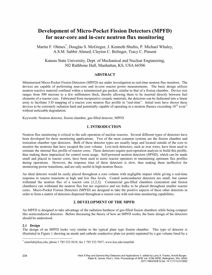
2.3.3 Alumina tape substrate A prospective material that combines the positive aspects of alumina and Green Tape has been found. Alumina tape is an unfired alumina substrate material that is flexible and easily cut but retains the alumina characteristics after firing. This material will allow the easy punching of vias and channels prior to hardening. Different layers of alumina tape can be laminated together by simply misting the surfaces with isopropyl alcohol and then hand pressing them together. The only difficulty of using the alumina tape is that it must be fired at temperatures at least 1650˚C. This material will allow the development of MPFDs to be an in-house, inexpensive process.
3. APPLICATION OF MPFD
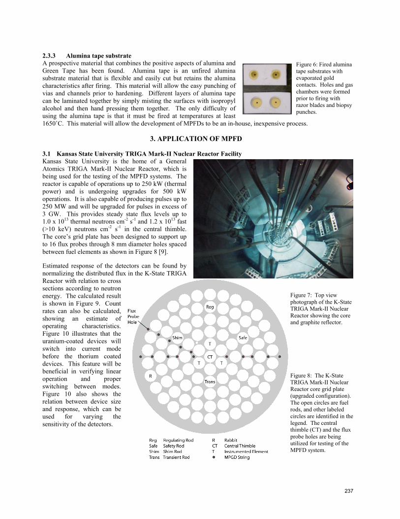
3.1 Kansas State University TRIGA Mark-II Nuclear Reactor Facility Kansas State University is the home of a General Atomics TRIGA Mark-II Nuclear Reactor, which is being used for the testing of the MPFD systems. The reactor is capable of operations up to 250 kW (thermal power) and is undergoing upgrades for 500 kW operations. It is also capable of producing pulses up to 250 MW and will be upgraded for pulses in excess of 3 GW. This provides steady state flux levels up to 1.0 x 10¹³ thermal neutrons cm-2 s-1 and 1.2 x 10¹³ fast (>10 keV) neutrons cm-2 s-1 in the central thimble. The core’s grid plate has been designed to support up to 16 flux probes through 8 mm diameter holes spaced between fuel elements as shown in Figure 8 [9].
Estimated response of the detectors can be found by normalizing the distributed flux in the K-State TRIGA Reactor with relation to cross sections according to neutron energy. The calculated result is shown in Figure 9. Count rates can also be calculated, showing an estimate of operating characteristics. Figure 10 illustrates that the uranium-coated devices will switch into current mode before the thorium coated devices. This feature will be beneficial in verifying linear operation and proper switching between modes. Figure 10 also shows the relation between device size and response, which can be used for varying the sensitivity of the detectors.
Figure 6: Fired alumina tape substrates with evaporated gold contacts. Holes and gas chambers were formed prior to firing with razor blades and biopsy punches.
Figure 7: Top view photograph of the K-State TRIGA Mark-II Nuclear Reactor showing the core and graphite reflector.
Figure 8: The K-State TRIGA Mark-II Nuclear Reactor core grid plate (upgraded configuration). The open circles are fuel rods, and other labeled circles are identified in the legend. The central thimble (CT) and the flux probe holes are being utilized for testing of the MPFD system.
238
3.2 MPFD configuration in the reactor Placing a string of MPFD triads (235U, 232Th, and a blank) in each flux probe hole will give a semi-three-dimensional array of detectors throughout the core. To do this, five triads will be formed into a detector string with five strings forming a bundle. At the top of the bundle will be a preamp box. A total of three bundles (15 strings, 75 triads, or 225 detectors) will be used to map out a plane in the K-State TRIGA Reactor core.
A string of detectors will be formed into three pieces of 17” long alumina substrate as depicted in Figure 11. Spaces between triads will be used for gas storage chambers with a channel connecting all the triads and chambers together. This will help keep the pressure constant throughout all of the detectors while also keeping the ratio of argon or P-10 gas high compared to the fission released gases. The channel will also be integral to the gas filling of the detectors. After all bakes have been completed in the fabrication of the detectors, the string will be placed in a vacuum chamber and backfilled with the fill gas. The string will then have the ends of the chamber sealed, trapping the highest quality fill gas inside.
Figure 12 shows how an MPFD string will be positioned in an aluminum tube that will be inserted in one of the flux probe holes. The top index will sit on the upper grid plate aligning the detector string with the fuel meat. The pin at the base of the tube will fit in the bottom grid plate, holding the tube vertical. To prevent neutron streaming, the flux probes will be backfilled with alumina powder and an offset will be incorporated in the preamp box. Tying five strings together will also lock the detector orientation to prevent flux probe rotation.
Reactor Power (watts)100 101 102 103 104 105
Cou
nt R
ate
(CP
S)
10-310-210-1100101102103104105106107108109
Pulse ModeOperation Limit
2 mm dia.1.5 mm
1 mm
2 mm dia.1.5 mm1 mm2.0 µm Th-232
0.5 µm U-235
Figure 9: Calculated normalized reaction rate response for 235U and 232Th MPFDs as a function of neutron energy distribution in the KSU TRIGA Mark II Nuclear Reactor
Figure 10: Calculated count rate as a function of reactor power.
Figure 11: Section of a string of triads with gas storage chamber and channel.
Figure 12: MPFD string inserted in an aluminum flux probe tube.
239
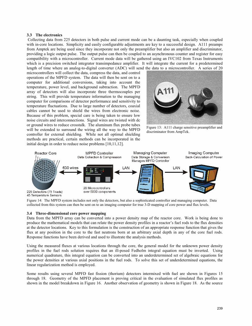
3.3 The electronics Collecting data from 225 detectors in both pulse and current mode can be a daunting task, especially when coupled with in-core locations. Simplicity and easily configurable adjustments are key to a successful design. A111 preamps from Amptek are being used since they incorporate not only the preamplifier but also an amplifier and discriminator, providing a logic output pulse. The output pulse can then be coupled to an asynchronous counter and register for easy compatibility with a microcontroller. Current mode data will be gathered using an IVC102 from Texas Instruments which is a precision switched integrator transimpedance amplifier. It will integrate the current for a predetermined length of time where an analog-to-digital converter (ADC) will send the data to a microcontroller. A series of 20 microcontrollers will collect the data, compress the data, and control operations of the MPFD system. The data will then be sent on to a computer for additional conversions, taking into account the temperature, power level, and background subtraction. The MPFD array of detectors will also incorporate three thermocouples per string. This will provide temperature information to the managing computer for comparisons of detector performance and sensitivity to temperature fluctuations. Due to large number of detectors, coaxial cables cannot be used to shield the wires from electronic noise. Because of this problem, special care is being taken to ensure low noise circuits and interconnections. Signal wires are twisted with dc or ground wires to reduce crosstalk. The aluminum flux probe tubes will be extended to surround the wiring all the way to the MPFD controller for external shielding. While not all optimal shielding methods are practical, certain methods can be incorporated in the initial design in order to reduce noise problems [10,11,12].
3.4 Three-dimensional core power mapping Data from the MPFD array can be converted into a power density map of the reactor core. Work is being done to produce the mathematical models that can relate the power density profiles in a reactor’s fuel rods to the flux densities at the detector locations. Key to this formulation is the construction of an appropriate response function that gives the flux at any position in the core to the fast neutrons born at an arbitrary axial depth in any of the core fuel rods. Response functions have been derived and used to illustrate the analysis methods.
Using the measured fluxes at various locations through the core, the general model for the unknown power density profiles in the fuel rods solution requires that an ill-posed Fedholm integral equation must be inverted. Using numerical quadrature, this integral equation can be converted into an underdetermined set of algebraic equations for the power densities at various axial positions in the fuel rods. To solve this set of underdetermined equations, the linear regularization method is employed.
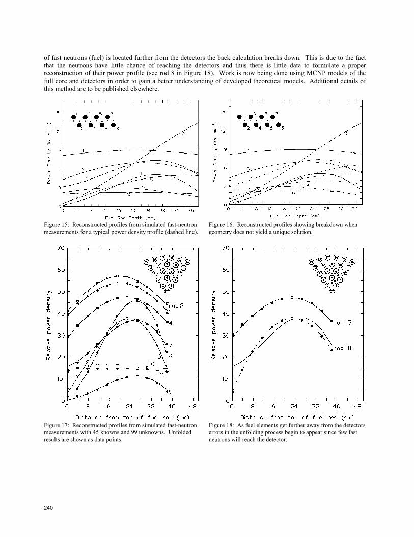
Some results using several MPFD fast fission (thorium) detectors intermixed with fuel are shown in Figures 15 through 18. Geometry of the MPFD placement is proving critical in the evaluation of simulated flux profiles as shown in the model breakdown in Figure 16. Another observation of geometry is shown in Figure 18. As the source
Figure 13: A111 charge sensitive preamplifier and discriminator from AmpTek.
Figure 14: The MPFD system includes not only the detectors, but also a sophisticated controller and managing computer. Data collected from this system can then be sent on to an imaging computer for true 3-D mapping of core power and flux levels.
240
of fast neutrons (fuel) is located further from the detectors the back calculation breaks down. This is due to the fact that the neutrons have little chance of reaching the detectors and thus there is little data to formulate a proper reconstruction of their power profile (see rod 8 in Figure 18). Work is now being done using MCNP models of the full core and detectors in order to gain a better understanding of developed theoretical models. Additional details of this method are to be published elsewhere.
Figure 15: Reconstructed profiles from simulated fast-neutron measurements for a typical power density profile (dashed line).
Figure 16: Reconstructed profiles showing breakdown when geometry does not yield a unique solution.
Figure 17: Reconstructed profiles from simulated fast-neutron measurements with 45 knowns and 99 unknowns. Unfolded results are shown as data points.
Figure 18: As fuel elements get further away from the detectors errors in the unfolding process begin to appear since few fast neutrons will reach the detector.
241
RESULTS
A proof-of-concept detector constructed with a 1 mm diameter, 2 mm deep pocket and a neutron reactive coating of 98% enriched 10B produced the results shown in Figure 19. Once above a certain threshold, this device showed very little fluctuation in operating characteristics even when the bias changed substantially. Comparing the 100 V spectrum to that of the 200 V spectrum shows that the device can be operated with a simple power supply located some distance from the detector without concern.
A recently constructed device containing a 3 mm diameter, 1 mm deep gas pocket and a natural uranium coating yielded spectacular results. Shows the spectrum collected by this chamber in a beam with approximately 108 cm-2 s-1 neutrons and 105 mR/h gammas. Shows the background, or gamma, spectrum gathered by the detector when one inch of cadmium was placed in the beam to filter out the neutrons. Not a single count was recorded until the low-level discriminator was set below channel 4 on the MCA. This test proves that the fission detector is resistant to background noise and that it works!
CONCLUSION
While this three-year project has just begun, progress is being demonstrated in the development of detector design and fabrication along with mathematical models for construction of 3-D core power mapping. The MPFD system will provide insight in reactor dynamics with its real-time response and distribution throughout the core. Tracking of flux profiles and reactor response to control rod movements will be just a few of the benefits of this system. Materials and methods of construction are being investigated and will allow the MPFDs to be inserted in boiling water reactors, pressurized water reactors, naval reactors, and even the new generation IV reactors. This system has the potential of being incorporated in fuel bundles for seamless integration into today’s reactor plants.
Figure 19: Proof-of-concept device showing steady operating characteristics for large bias changes beyond a certain threshold.
Figure 20: Spectrum from natural uranium coated fission detector placed in a neutron beam with a large gamma background.
Figure 21: Background spectrum from natural uranium coated fission detector shielded by one inch of cadmium to filter out neutrons. Notice that not a single count was recorded – no background detected!
242
MPFDs are simple, small, and inexpensive fission chambers built of temperature and radiation hard materials. They will provide point detection of thermal and fast neutron flux levels. An array of detectors will provide data that can be developed into core power mapping profiles.
ACKNOWLEDGEMENTS
The authors express their gratitude to Dr. Kimberlee Hoffert from Reuter Stokes for her assistance with Uranium deposition techniques and to Dan Kruger and Peter Scheuer from Honeywell, Kansas City Plant for their assistance with Alumina Tape firing. All of the devices were constructed using the S.M.A.R.T. (Semiconductor Materials and Radiological Technologies) Laboratory. Testing of the devices is being done at the TRIGA Mark-II Nuclear Reactor Facility. Both facilities are located in the Department of Mechanical and Nuclear Engineering at Kansas State University. Research has been supported under the Department of Energy Nuclear Engineering Research Initiative (NERI) Grant # DE-FG07-02SF22611.
REFERENCES
1. G. F. Knoll, Radiation Detection and Measurement, John Wiley & Sons, Inc., New York, 2000. 2. H. K. Gersch, D. S. McGregor, and P. A. Simpson, “A Study of the Effect of Incremental Gamma-Ray Doses and
Incremental Neutron Fluences Upon the Performance of Self-Biased 10B-Coated High-Purity Epitaxial GaAs Thermal Neutron Detectors,” Nuclear. Instrumentation and Methods, A489, 85, 2002.
3. N. Tsoulfanidis, Measurement and Detection of Radiation, Taylor & Francis, Washington, 1995. 4. J. K. Shultis and R. E. Faw, Fundamentals of Nuclear Science and Engineering, Marcel Dekker, Inc., New York,
2002. 5. J. F. Ziegler and J. P. Biersack, SRIM-2000 Code, Version 9, IBM Company, 1998. 6. J. F. Kircher and R. E. Bowman, Effects of Radiation on Materials and Components, Reinhold Publishing
Corporation, New York, 1964. 7. W. H. Gitzen, Alumina as a Ceramic Material, The American Ceramic Society, Columbus, Ohio, 1970. 8. Dupont, “Green Tape”, http://www.dupont.com/mcm/product/tape.html, 2003. 9. Kansas State University TRIGA Mark II Nuclear Reactor Facility, Training Manual, 2002. 10. H. W. Ott, Noise Reduction Techniques in Electronic Systems, John Wiley & Sons, New York, 1988. 11. P. Horowitz and W. Hill, The Art of Electronics, Cambridge University Press, Cambridge, 1989. 12. W. J. Dally and J. W. Poulton, Digital Systems Engineering, Cambridge University Press, Cambridge, 1998.