This article aimed to describe the design and building of a 3-axis mini computer numerical control (CNC) machine for making a ceramic cup and bowl prototype that helps achieve a fully-automated production process using a small budget. Step motors were used to control the movement of the 3 axes, X, Y, and Z axis, of the Mini CNC machine. Automated operating system was controlled through unipolar microstepping driver and spindle adjustment PC interface board. The operating system was controlled by Mach 3 software, G-code command. Based on a test using a prototype milling of a lotus leaf ceramic bowl with a diameter of 130 centimeter and height of 65 millimeter, it was found that the depth of cut in milling each round was 6 millimeter, the test of building a dry clay lotus leaf bowl with a hard plaster lotus leaf bowl, fine milling with feeding speed of 1000 - 3,000 (mm / min), and increasing the spindle speed of 10,000 - 15,000 (rpm), circular milling cutter with a depth of 0.1 (mm). In each circular, the increase of the feeding speed and the spindle speed would reduce the time required for building. The smoothness of the lotus leaf bowl surface depended on the hardness of the material used to make the prototype. When comparing the performance with the 5-axis CNC machines on the market, it was found that the performance was similar, but the Mini CNC Machine had size, weight, and price less than others.
Keywords: Ceramic, G-code, mini CNC
INTRODUCTION
Manufacturing high quality products with time saving and cost saving in the production process is a basic need of industry operators in a highly competitive situation. Therefore, it is necessary to employ a computer system
to assist in manufacturing (Computer Integrated Manufacturing, CIM) (Delaram & Valilai, 2018). A basic principle of computer integrated manufacturing involves computer numerical control or CNC using a CNC machine is more precise than humans (Li, et al., 2020).
There are different types of CNC machines in the market and the popular ones are 2-axis and 3-axis CNC machines (Yousefian, et al., 2020). Major components of CNC machines are mechanical design, drive modules, and system software (Lin & Koren, 1996). Mechanical design is composed of system structure, drive modules consist of microprocessor, and the last part – system software used for milling a work-piece is controlled by G-code command and NC-code command (Madekar, et al., 2016).
Mini CNC machine uses the same operating system as other CNC machines but the objective of the maker is to save cost in purchasing a large and expensive CNC machine with redundant mechanisms more than necessary for medium-sized and small-sized enterprises including moving and installation that requires a large place and specialists (Sarkar, et al., 2020).
Mini CNC ceramics machine is an automated milling machine for prototyping ceramic cups and bowls. It can facilitate milling prototypes from 50 millimeter circumference and 50 millimeter height to 100 millimeter circumference and 200 millimeter height. The machine structure is conveniently installed and moved. Its operative system is similar to that of other CNC machines. A 3-D model using computer-aided design is saved in the dwg file type. The file is converted into a path of the machine using G-code command or NC-code command. The prototype obtained from the CNC ceramic milling machine is exactly like the design more precise than humans and the price of the machine is cheaper than the ones in the market (Jinan Style Machinery Co., L., 2021).
MATERIALS AND METHOD
Mini CNC Machine
CNC technology has been widely used in the production process. Moreover, a control board is cheap and bought easily these days like each model of Arduino board designed to support mini CNC machine which can be applied to other devices easily because a free software download is offered for control software including software used for the development (Hirani, 2019). Currently, a mini milling machine is developed to serve various kinds of automatic work such as the development of automatic plotter and automatic PCB cutting machine. The purpose of making the mini CNC machine is cost saving and it can be used with PC, Arduino ATMEGA 328 control board that is cheap and easy to find. It can facilitate G-code command for PCB drawing and drilling, CD/DVD writer, stepper motors, Servo motor, motor drivers, and design of 2-D building sketch (Kumar, et al., 2017).
Utilizing CNC technology to make ceramic prototypes for replacing conventional manufacturing process- Producing a prototype mold is a time-consuming process. Solid
Development of Mini CNC Machine Design and Building
Work software used to design ceramic products can reduce design time and a path of milling can be checked before feeding to CNC machine for making a ship prototype and a prototype model. The findings from this study indicated that new technology can help artists produce their pieces of work with Solidwork software and make a product prototype using a CNC machine based on an interdisciplinary approach between ceramic production process and digital production technology (Yousefian, 2020).
3-Axis CNC Machine
The design and development of 3-Axis CNC router machine with microcontroller can achieve a variety of complex workpieces with low cost. The machine supports cutting, reaming, marking, drilling, and milling for wood, acrylic, and PCB box. The microcontroller can facilitate design and image processing software such as ArtCam and InkScape that can convert the movement procedure of end mills in milling and reaming using G-code and GRBL software to control the operating system of the mini CNC machine. Test results and precision test showed that the machine can work efficiently on a work area of 280 width, 170 length, and 65 millimeter height (Patel et al., 2019).
Implementation
The mini CNC ceramic machine consists of 3 subsystems, i.e. mechanical system, electronic system, and computer software. The steps for making the machine are as follow:
Step 1 – design operating control electrical circuitStep 2- design operating mechanismStep 3 – install hardware devicesStep 4 – design workpieces for testing the machine operating systemStep 5 – compare milling efficiency on each material.
Step to Design Operating Control Electrical Circuit
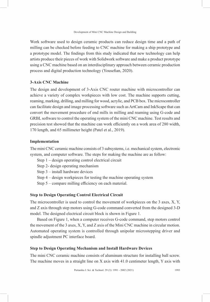
The microcontroller is used to control the movement of workpieces on the 3 axes, X, Y, and Z axis through step motors using G-code command converted from the designed 3-D model. The designed electrical circuit block is shown in Figure 1.
Based on Figure 1, when a computer receives G-code command, step motors control the movement of the 3 axes, X, Y, and Z axis of the Mini CNC machine in circular motion. Automated operating system is controlled through unipolar microstepping driver and spindle adjustment PC interface board.
Step to Design Operating Mechanism and Install Hardware Devices
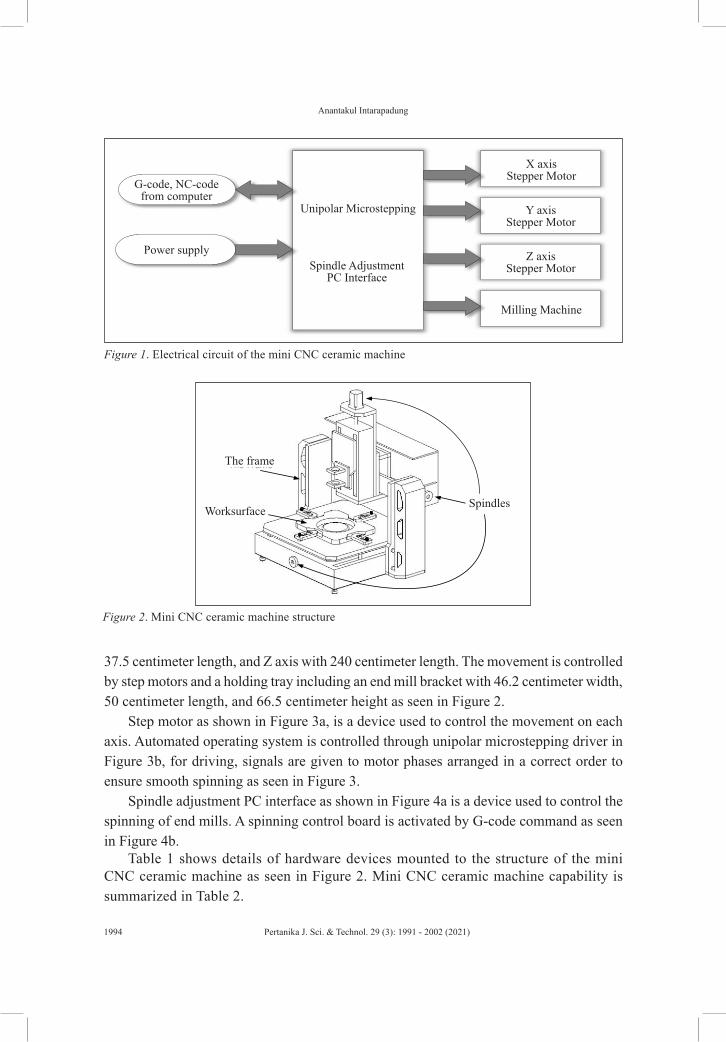
The mini CNC ceramic machine consists of aluminum structure for installing ball screw. The machine moves in a straight line on X axis with 41.0 centimeter length, Y axis with
37.5 centimeter length, and Z axis with 240 centimeter length. The movement is controlled by step motors and a holding tray including an end mill bracket with 46.2 centimeter width, 50 centimeter length, and 66.5 centimeter height as seen in Figure 2.
Step motor as shown in Figure 3a, is a device used to control the movement on each axis. Automated operating system is controlled through unipolar microstepping driver in Figure 3b, for driving, signals are given to motor phases arranged in a correct order to ensure smooth spinning as seen in Figure 3.
Spindle adjustment PC interface as shown in Figure 4a is a device used to control the spinning of end mills. A spinning control board is activated by G-code command as seen in Figure 4b.
Table 1 shows details of hardware devices mounted to the structure of the mini CNC ceramic machine as seen in Figure 2. Mini CNC ceramic machine capability is summarized in Table 2.
Figure 1. Electrical circuit of the mini CNC ceramic machine
Table 2Details of the mini CNC ceramic machine capability
Item DetailsWork area Work area of (X axis) mm. * 300 (Y axis) mm. * 150 (Z axis) mm.Height ≥ 70 mm.Machine Size 625 × 510 × 410 mmConnection USB portLinear and driving system Driving X,Y,Z axis using ball screws and round shaft linear slide.Driving motor Step motor with a speed of 1440 rounds/second.Spindle With a speed of 20,000 rounds per minute (rpm).Speed in milling 0-3500 mm/minPrecision The machine is commanded to move at least 0.0025 mm.Milling speed 0-3500 mm/minPrecise positioning ± 0.05 mmCommand code G-code / NC-codeWeight of machine 60 kg.Structure of machine Aluminum alloys
4. IC IC alternating current AC socket 3 legMilling deviceEnd mill Maktec MT910, 20,000 millimeter/minute 260 watt, end mill size = 6.35
millimeterElectrical systemElectricity 220 volt AC
Table 1 (continue)
Linear system
Step to Design Work Piece for Testing the Machine Operating System
Software designed to control the operating system of the mini CNC ceramic machine comprises 2 parts as one part used to design shapes of 3-D ceramic products and the part used to control the operating system of the machine for milling workpieces to meet the designed shapes. The software used to design shapes of ceramic products in this study, a lotus leaf ceramic bowl, with a diameter of 130 centimeter and height of 65 millimeter, was Aspire 8.0 as seen in Figure 5.
The Aspire 8.0 was converted to the command for the movement of end mills using Mach 3 software, G-code command as seen in Figure 6.
RESULTS AND DISCUSSIONS
Outcome of Assembly of structure
The designed structure and controller in this study can facilitate the installation of prototype
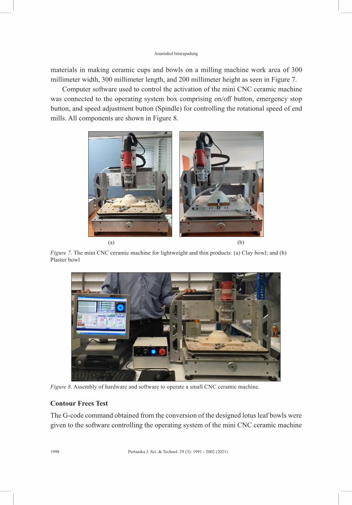
materials in making ceramic cups and bowls on a milling machine work area of 300 millimeter width, 300 millimeter length, and 200 millimeter height as seen in Figure 7.
Computer software used to control the activation of the mini CNC ceramic machine was connected to the operating system box comprising on/off button, emergency stop button, and speed adjustment button (Spindle) for controlling the rotational speed of end mills. All components are shown in Figure 8.
Figure 7. The mini CNC ceramic machine for lightweight and thin products: (a) Clay bowl; and (b) Plaster bowl
Figure 8. Assembly of hardware and software to operate a small CNC ceramic machine.
(a) (b)
Contour Frees Test
The G-code command obtained from the conversion of the designed lotus leaf bowls were given to the software controlling the operating system of the mini CNC ceramic machine
Development of Mini CNC Machine Design and Building
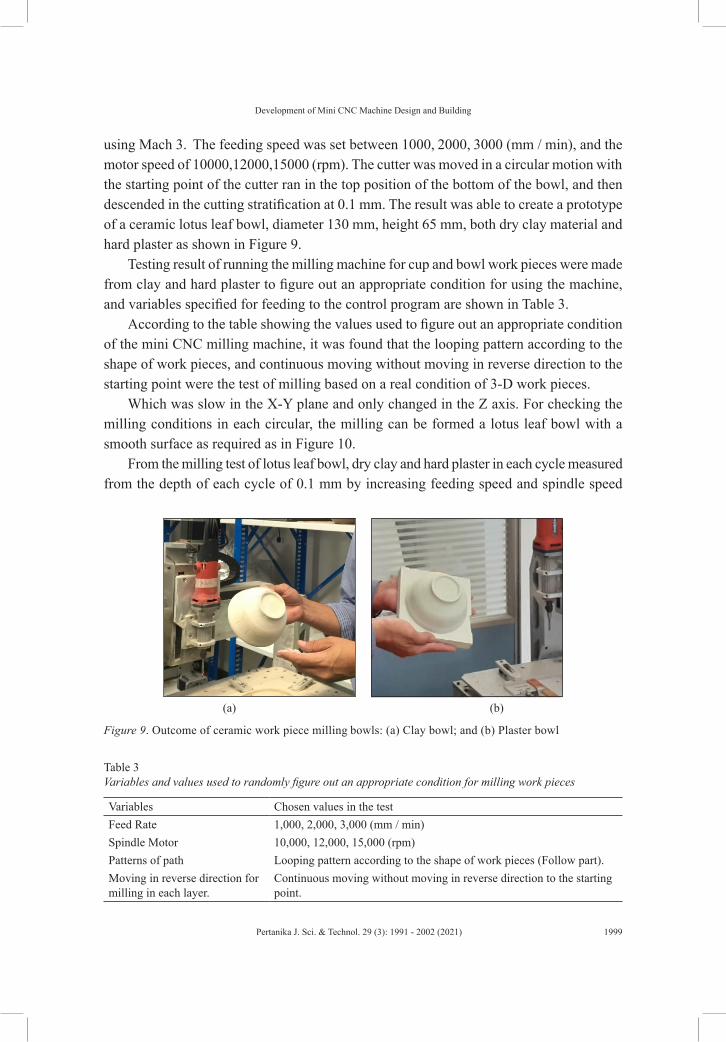
using Mach 3. The feeding speed was set between 1000, 2000, 3000 (mm / min), and the motor speed of 10000,12000,15000 (rpm). The cutter was moved in a circular motion with the starting point of the cutter ran in the top position of the bottom of the bowl, and then descended in the cutting stratification at 0.1 mm. The result was able to create a prototype of a ceramic lotus leaf bowl, diameter 130 mm, height 65 mm, both dry clay material and hard plaster as shown in Figure 9.
Testing result of running the milling machine for cup and bowl work pieces were made from clay and hard plaster to figure out an appropriate condition for using the machine, and variables specified for feeding to the control program are shown in Table 3.
According to the table showing the values used to figure out an appropriate condition of the mini CNC milling machine, it was found that the looping pattern according to the shape of work pieces, and continuous moving without moving in reverse direction to the starting point were the test of milling based on a real condition of 3-D work pieces.
Which was slow in the X-Y plane and only changed in the Z axis. For checking the milling conditions in each circular, the milling can be formed a lotus leaf bowl with a smooth surface as required as in Figure 10.
From the milling test of lotus leaf bowl, dry clay and hard plaster in each cycle measured from the depth of each cycle of 0.1 mm by increasing feeding speed and spindle speed
Figure 9. Outcome of ceramic work piece milling bowls: (a) Clay bowl; and (b) Plaster bowl
Table 3Variables and values used to randomly figure out an appropriate condition for milling work pieces
Variables Chosen values in the testFeed Rate 1,000, 2,000, 3,000 (mm / min)Spindle Motor 10,000, 12,000, 15,000 (rpm)Patterns of path Looping pattern according to the shape of work pieces (Follow part).Moving in reverse direction for milling in each layer.
Continuous moving without moving in reverse direction to the starting point.
Table 4Test result with the lotus leaf bowl made from dry clay
Test of slow movement with looping patternFeeding speed (mm/min) 1,000 2,000 3,000Spindle Speed (rpm) 10,000 12,000 15,000Step Down Pass Depth (mm) 0.1 0.1 0.1Total Machine Time 2.05 1.47 1.12
Table 5Test result with the lotus bowl made from hard plaster
Test of slow movement with looping patternFeeding speed (mm/min) 1,000 2,000 3,000Spindle Speed (rpm) 10,000 12,000 15,000Step Down Pass Depth (mm) 0.1 0.1 0.1Total Machine Time 2.38 2.15 1.45
Figure 10. Outcome of milling ceramic work pieces of bowls
was found to be a little different. It depended on the speed and hardness of the material used as in Tables 4 and 5.
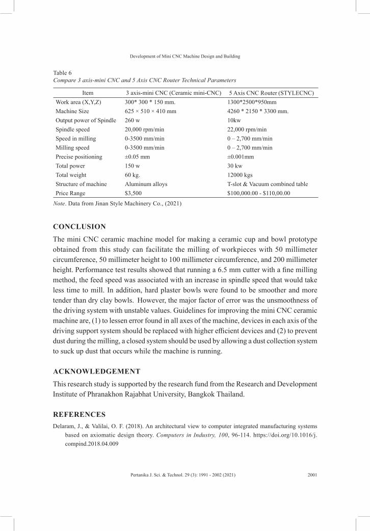
When comparing the milling efficiency from Table 4 and 5, it was found that the time difference was slight. The dry clay lotus leaf bowls took less time than the small plaster lotus leaf bowls. The smoothness of the skin was similar and met the needs of ceramic operators. The performance comparison results of the 3-axis mini CNC ceramic milling machine with commercially available 5-axis mini CNC machines were as shown in Table 6.
By comparison with the 5-axis CNC machines (Jinan Style Machinery Co., 2021) that were available in the market, the performance was similar, but the mini CNC machines were much cheaper. The size and weight of the machine were also less, so it was suitable for small ceramic enterprises (SMEs) who wanted to reduce their production capital and had less production space.
Development of Mini CNC Machine Design and Building
CONCLUSION
The mini CNC ceramic machine model for making a ceramic cup and bowl prototype obtained from this study can facilitate the milling of workpieces with 50 millimeter circumference, 50 millimeter height to 100 millimeter circumference, and 200 millimeter height. Performance test results showed that running a 6.5 mm cutter with a fine milling method, the feed speed was associated with an increase in spindle speed that would take less time to mill. In addition, hard plaster bowls were found to be smoother and more tender than dry clay bowls. However, the major factor of error was the unsmoothness of the driving system with unstable values. Guidelines for improving the mini CNC ceramic machine are, (1) to lessen error found in all axes of the machine, devices in each axis of the driving support system should be replaced with higher efficient devices and (2) to prevent dust during the milling, a closed system should be used by allowing a dust collection system to suck up dust that occurs while the machine is running.
ACKNOWLEDGEMENT
This research study is supported by the research fund from the Research and Development Institute of Phranakhon Rajabhat University, Bangkok Thailand.
REFERENCESDelaram, J., & Valilai, O. F. (2018). An architectural view to computer integrated manufacturing systems
based on axiomatic design theory. Computers in Industry, 100, 96-114. https://doi.org/10.1016/j.compind.2018.04.009
Hirani, A. (2019). Design of mini CNC using arduino uno. Retrieved November 10, 2020, from https://www.irjet.net/archives/V6/i4/IRJET-V6I41201.pdf
Jinan Style Machinery Co., L. (2021). 5 axis CNC router technical parameters. Retrieved February 8, 2021, from https://www.stylecnc.com/5-axis-cnc-machine/5-axis-cnc-router.html
Kumar, M. A., Krishnaraj, J., & Reddy, R. B. G. S. (2017). Mini CNC 2D sketcher for accurate building drawing. International Journal of Civil Engineering and Technology, 8(6), 543-549.
Li, B., Zhang, H., Ye, P., & Wang, J. (2020). Trajectory smoothing method using reinforcement learning for computer numerical control machine tools. Robotics and Computer-Integrated Manufacturing, 61, Article 101847. https://doi.org/10.1016/j.rcim.2019.101847
Lin, R. S., & Koren, Y. (1996). Real-time interpolators for multi-axis CNC machine tools. Manufacturing Systems, 25, 145-149.
Madekar, K. J., Nanaware, K. R., Phadtare, P. R., & Mane, V. S. (2016). Automatic mini CNC machine for PCB drawing and drilling. International Research Journal of Engineering and Technology (IRJET), 3(02), 1107-1108.
Patel, M. P. N., Pavagadhi, M. S. D., & Acharya, S. G. (2019). Design and development of portable 3-Axis CNC router machine. International Research Journal of Engineering and Technology (IRJET), 6(3), 1-452.
Sarkar, B., Khan, A. I., Rana, A. K., & Kundu, S. (2020). Quantification of the phase fraction in multiphase steel and 2D design using mini CNC plotter. In IOP Conference Series: Materials Science and Engineering (Vol. 810, No. 1, p. 012066). IOP Publishing. https://doi.org/10.1088/1757-899X/810/1/012066
Yousefian, O., Balabokhin, A., & Tarbutton, J. (2020). Point-by-point prediction of cutting force in 3-axis CNC milling machines through voxel framework in digital manufacturing. Journal of Intelligent Manufacturing, 31(1), 215-226. https://doi.org/10.1007/s10845-018-1442-7