TFAWS 2017 – August 21-25, 2017 1 DEVELOPMENT OF NASA’S SAMPLE CARTRIDGE ASSEMBLY: SUMMARY OF GEDS DESIGN, DEVELOPMENT TESTING, AND THERMAL ANALYSES Brian O'Connor 1 , Deborah Hernandez 2 , Linda Hornsby 2 , Maria Brown 2 Kathryn Horton-Mullins 3 NASA Marshall Space Flight Center, Huntsville AL 35812 ABSTRACT NASA’s Sample Cartridge Assembly (SCA) project is responsible for designing and validating a payload that contains materials research samples in a sealed environment. The SCA will be heated in the European Space Agency’s (ESA) Low Gradient Furnace (LGF) that is housed inside the Material Science Research Rack (MSRR) located on the International Space Station (ISS). The first Principle Investigator (PI) to utilize the SCA will focus on Gravitational Effects on Distortion in Sintering (GEDS) research. This paper will give a summary of the design and development test effort for the GEDS SCA and will discuss the role of thermal analysis in developing test profiles to meet the science and engineering requirements. Lessons learned will be reviewed and salient design features that may differ for each PI will be discussed. INTRODUCTION NASA’s Sample Cartridge Assembly (SCA) project is responsible for designing and validating a payload that contains materials research samples that will be processed in ESA’s Low Gradient Furnace (LGF) inserted into the Materials Science Research Rack (MSRR) on International Space Station (ISS). MSRR, shown in Figure 1, was launched in 2009 and installed in ISS’s Destiny Lab (Ref 1). The right side of MSRR consists of the European Space Agency (ESA) Materials Science Lab (MSL). MSL contains a vacuum chamber that accepts different furnace inserts. ESA currently has two furnace inserts available for use by Principle Investigators (PIs), the LGF and Solidification Quench Furnace (SQF). The LGF is a Bridgman furnace consisting of a hot and cold zone separated by an adiabatic zone used for directional solidification or isothermal processing up to 1400°C. Since the LGF does not have quench capability it has a larger bore diameter and produces lower gradients. ESA offers a version of a SCA that can be processed using the LGF or SQF insert, see Figure 1, and has processed a number of SCAs in both furnaces (Ref 2). The SCA that has been developed at NASA Marshall Space Flight Center (MSFC) features a larger diameter, processed at high temperatures with thermal gradients up to 40 °K/cm, and processing in an argon environment. MSFC SCA has a diameter of 26mm as opposed to the ESA SCA at 16mm. It is qualified to 1294°C and each cartridge and head assembly can be processed up to three times. Further MSFC’s SCA has a single pressurized volume within both the cartridge tube and head filled with
Transcript
TFAWS 2017 – August 21-25, 2017 1
DEVELOPMENT OF NASA’S SAMPLE CARTRIDGE ASSEMBLY: SUMMARY OF GEDS DESIGN, DEVELOPMENT TESTING, AND THERMAL ANALYSES
Brian O'Connor1, Deborah Hernandez2, Linda Hornsby2, Maria Brown2
Kathryn Horton-Mullins3
NASA Marshall Space Flight Center, Huntsville AL 35812
ABSTRACT
NASA’s Sample Cartridge Assembly (SCA) project is responsible for designing and validating a payload that contains materials research samples in a sealed environment. The SCA will be heated in the European Space Agency’s (ESA) Low Gradient Furnace (LGF) that is housed inside the Material Science Research Rack (MSRR) located on the International Space Station (ISS). The first Principle Investigator (PI) to utilize the SCA will focus on Gravitational Effects on Distortion in Sintering (GEDS) research. This paper will give a summary of the design and development test effort for the GEDS SCA and will discuss the role of thermal analysis in developing test profiles to meet the science and engineering requirements. Lessons learned will be reviewed and salient design features that may differ for each PI will be discussed.
INTRODUCTION
NASA’s Sample Cartridge Assembly (SCA) project is responsible for designing and validating a payload that contains materials research samples that will be processed in ESA’s Low Gradient Furnace (LGF) inserted into the Materials Science Research Rack (MSRR) on International Space Station (ISS). MSRR, shown in Figure 1, was launched in 2009 and installed in ISS’s Destiny Lab (Ref 1). The right side of MSRR consists of the European Space Agency (ESA) Materials Science Lab (MSL). MSL contains a vacuum chamber that accepts different furnace inserts. ESA currently has two furnace inserts available for use by Principle Investigators (PIs), the LGF and Solidification Quench Furnace (SQF). The LGF is a Bridgman furnace consisting of a hot and cold zone separated by an adiabatic zone used for directional solidification or isothermal processing up to 1400°C. Since the LGF does not have quench capability it has a larger bore diameter and produces lower gradients.
ESA offers a version of a SCA that can be processed using the LGF or SQF insert, see Figure 1, and has processed a number of SCAs in both furnaces (Ref 2). The SCA that has been developed at NASA Marshall Space Flight Center (MSFC) features a larger diameter, processed at high temperatures with thermal gradients up to 40 °K/cm, and processing in an argon environment. MSFC SCA has a diameter of 26mm as opposed to the ESA SCA at 16mm. It is qualified to 1294°C and each cartridge and head assembly can be processed up to three times. Further MSFC’s SCA has a single pressurized volume within both the cartridge tube and head filled with
TFAWS 2017 – August 21-25, 2017 2
gaseous argon, while ESA’s SCA is helium filled within the cartridge tube only. This should allow for a cost effective SCA that will accommodate a wide range of larger diameter science experiments.
This paper will provide an overview of the design and development test effort of NASA’s SCA specific to accommodating the first Principle Investigator PI to utilize the SCA. The first PI will focus on Gravitational Effects on Distortion in Sintering (GEDS) research and is manifested to fly to the ISS in early to mid-2018. A discussion of the role of transient thermal analysis in developing pre-flight ground test and flight profiles to meet the science and engineering requirements will be covered. Lessons learned during the SCA development process will be reviewed and salient design features will be discussed. An overview of NASA’s SCA and the thermal analysis method, as well as, early testing on the first integrated SCA, testing done to measure the conductivity of the cartridge and a discussion on the braze process and profile development have been previously documented (Ref 3).
Figure 1 Material Science Research Rack and ESA’s SCA
NASA SCA DESIGN
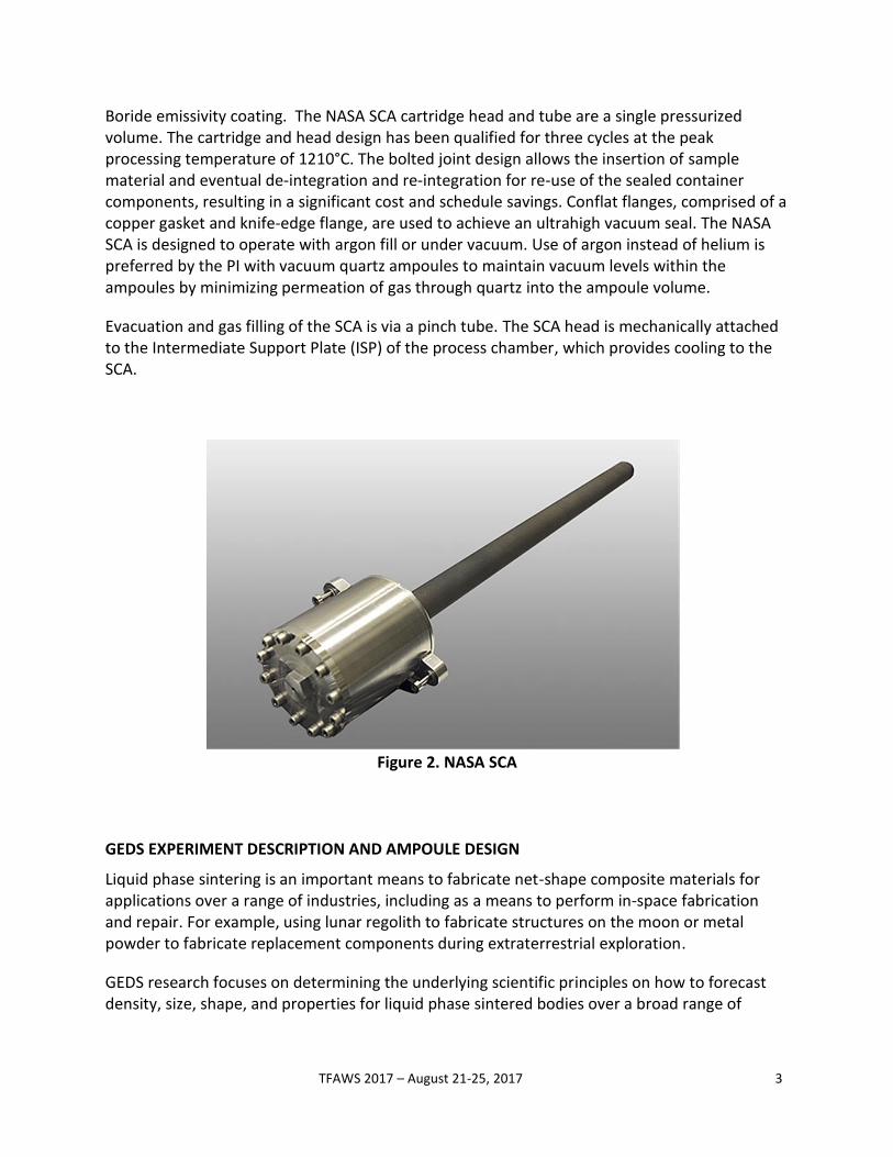
A complete NASA SCA unit consists of a cartridge head and a cylindrical tube as pictured in Figure 2. The Instrument Head is made of 416 CRES. The cartridge tube is a Vacuum Plasma Sprayed tube of Molybdenum-Rhenium (Mo-41Re), (Ref 4) with an Alumina liner and Zirconium
TFAWS 2017 – August 21-25, 2017 3
Boride emissivity coating. The NASA SCA cartridge head and tube are a single pressurized volume. The cartridge and head design has been qualified for three cycles at the peak processing temperature of 1210°C. The bolted joint design allows the insertion of sample material and eventual de-integration and re-integration for re-use of the sealed container components, resulting in a significant cost and schedule savings. Conflat flanges, comprised of a copper gasket and knife-edge flange, are used to achieve an ultrahigh vacuum seal. The NASA SCA is designed to operate with argon fill or under vacuum. Use of argon instead of helium is preferred by the PI with vacuum quartz ampoules to maintain vacuum levels within the ampoules by minimizing permeation of gas through quartz into the ampoule volume.
Evacuation and gas filling of the SCA is via a pinch tube. The SCA head is mechanically attached to the Intermediate Support Plate (ISP) of the process chamber, which provides cooling to the SCA.
Figure 2. NASA SCA
GEDS EXPERIMENT DESCRIPTION AND AMPOULE DESIGN
Liquid phase sintering is an important means to fabricate net-shape composite materials for applications over a range of industries, including as a means to perform in-space fabrication and repair. For example, using lunar regolith to fabricate structures on the moon or metal powder to fabricate replacement components during extraterrestrial exploration.
GEDS research focuses on determining the underlying scientific principles on how to forecast density, size, shape, and properties for liquid phase sintered bodies over a broad range of
TFAWS 2017 – August 21-25, 2017 4
compositions and gravitational conditions (Ref 5). The gravity role is convoluted. Analysis and optimization of liquid phase sintering is impossible without understanding the interplay of surface energy and gravity. Surface energy delivers an internal stress, termed the sintering stress, which pulls grains into contact to densify the body. However, gravity is an additional force, leading to shape distortion, substrate friction during shrinkage, and stratification of dense solid and gas filled pores. Microgravity experiments are important in separating the surface energy from the gravity factors, providing a basis for assessing constitutive parameters, such as the effective viscosity, and determination of the appropriate constitutive model – linear or nonlinear. The approach is to utilize experimental data to help develop a rheological model for sintering, with and without gravity, starting with compacted mixtures of W, Ni, Cu, and Mn powders formed into homogeneous cylinders. Interrupted sintering experiments provide a means to critically compare and contrast several parameters during liquid phase sintering.
Seven flight SCAs are planned, each containing seven samples. The samples will be dimensioned, weighed, and vacuum sealed in quartz encapsulation. The key measures of density, component shape, and microstructure will be collected on samples processed to different times. The contrast and comparison of samples and processing parameters from ground and flight experiments will help to separate the confusion of variables, including the effective viscosity evolution during liquid phase sintering, to formulate a model of wide applicability relevant to in-space fabrication and repair.
Sintering with a liquid phase occurs at 1200°C. To capture the microstructure evolution as liquid forms, equally spaced logarithmic isothermal hold times are desired. The required isothermal is +/- 5°C between all seven samples. These samples are processed above 1200°C for 3 to 60 minutes. Additionally, one run will stop just as liquid forms, nominally at 1180°C. Pre-flight and flight thermal profiles are determined by testing and transient analysis and extend beyond the original science requirements due to the design of the LGF and SCA which result in a time lag between when the furnace heaters and when experiment samples reach a specific temperature. The Sample Processing Program (SPP) controls the LGF ramp rates, heater set points, and heater hold times for processing. Control at the LGF level allows for repeatability between GEDS SCA processing with different hold times.
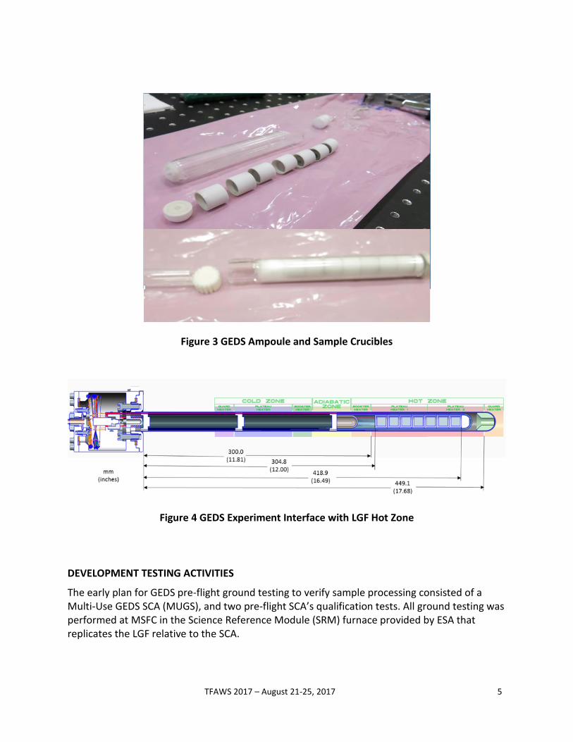
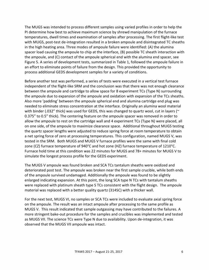
Each GEDS SCA consists of seven separate cylindrical samples (12 mm diameter by 12 mm height) contained in high purity alumina ceramic crucibles, all of which are contained within an evacuated quartz ampoule, as shown in Figure 3. The cartridge fill gas is argon instead of the typical helium to prevent ampoule permeation. Two quartz spacers and a cartridge end cap are used to position the ampoule within the cartridge tube such that all samples are located within the furnace isothermal hot zone plateau heaters during processing as shown in Figure 4. Four Type S, (platinum sheath, platinum rhodium-10% and platinum wire) thermocouples are used to monitor temperatures near the crucibles where the second and last samples are located, with redundancy provided in both locations. Additionally, two type N (tantalum sheath, nicrosil and nisil wire) thermocouples located near the SCA head are used for touch temperature evaluation.
TFAWS 2017 – August 21-25, 2017 5
Figure 3 GEDS Ampoule and Sample Crucibles
Figure 4 GEDS Experiment Interface with LGF Hot Zone
DEVELOPMENT TESTING ACTIVITIES
The early plan for GEDS pre-flight ground testing to verify sample processing consisted of a Multi-Use GEDS SCA (MUGS), and two pre-flight SCA’s qualification tests. All ground testing was performed at MSFC in the Science Reference Module (SRM) furnace provided by ESA that replicates the LGF relative to the SCA.
TFAWS 2017 – August 21-25, 2017 6
The MUGS was intended to process different samples using varied profiles in order to help the PI determine how best to achieve maximum science by shrewd manipulation of the furnace temperatures, dwell times and examination of samples after processing. The first flight-like test with MUGS, post-test de-integration resulted in a broken ampoule and disintegrated TC sheaths in the high heating area. Three modes of ampoule failure were identified: (A) the alumina spacer load causing the ampoule to chip at the interface, (B) possible TC sheath interaction with the ampoule, and (C) contact of the ampoule spherical end with the alumina end spacer, see Figure 5. A series of development tests, summarized in Table 1, followed the ampoule failure in an effort to eliminate points of failure from the design. This provided the opportunity to process additional GEDS development samples for a variety of conditions.
Before another test was performed, a series of tests were executed in a vertical test furnace independent of the flight-like SRM and the conclusion was that there was not enough clearance between the ampoule and cartridge to allow space for 8 experiment TCs (Type N) surrounding the ampoule due to expansion of the ampoule and oxidation with expansion of the TCs sheaths. Also more ‘padding’ between the ampoule spherical end and alumina cartridge end plug was needed to eliminate stress concentration at the interface. Originally an alumina wool material with binder (.032” thick) was used for GEDS, this was changed to quartz wool, cut in layers (~ 0.375” to 0.5” thick). The centering feature on the ampoule spacer was removed in order to allow the ampoule to rest on the cartridge wall and 4 experiment TCs (Type N) were placed, all on one side, of the ampoule to maximize clearance space. Additional throughout MUGS testing the quartz spacer lengths were adjusted to reduce spring force at room temperature to obtain a net spring force of zero at processing temperatures. This configuration, named MUGS V, was tested in the SRM. Both MUGS and MUGS V furnace profiles were the same with final cold zone (CZ) furnace temperature of 940°C and hot zone (HZ) furnace temperature of 1210°C. Furnace hold time at this condition was 22 minutes for MUGS and 78+ minutes for MUGS V to simulate the longest process profile for the GEDS experiment.
The MUGS V ampoule was found broken and SCA TCs tantalum sheaths were oxidized and deteriorated post test. The ampoule was broken near the first sample crucible, while both ends of the ampoule survived undamaged. Additionally the ampoule was found to be slightly enlarged indicating expansion. At this point, the long SCA type N TCs with tantalum sheaths were replaced with platinum sheath type S TCs consistent with the flight design. The ampoule material was replaced with a better quality quartz (314SC) with a thicker wall.
For the next test, MUGS VI, no samples or SCA TCs were included to evaluate axial spring force on the ampoule. The result was an intact ampoule after processing to the same profile as MUGS V. This result indicated that sample outgassing may have contributed to the failures. A more stringent bake-out procedure for the samples and crucibles was implemented and tested as MUGS VII. The science TCs were Type N due to availability. Upon de-integration, it was observed that the MUGS VII ampoule was intact.
TFAWS 2017 – August 21-25, 2017 7
After finally receiving the Type S TCs, a final development test was performed. A vibration test was executed prior to the MUGS VIII SCA testing in the SRM in order to mitigate risk of a failure during the vibration qualification test prior to flight. The ampoule remained intact after the MUGS VIII vibration test and SRM processing development test.
A final pre-flight test (G2) was performed in the SRM with full quality support to verify that GEDS will meet science requirements. For this final test, the processing profile was modified, after PI evaluation of MUGS series test samples showed less sintering than expected, from a 78 minute hold at 1210°C to a 95 minute hold. Additionally the cold zone heater setting was increased from 940°C used in the MUGS test to 1130°C. The development of the revised processing profile is discussed relative to the transient modeling in the next section. Additionally, the updated sample bake out process and new type S platinum sheath TCs were added to the G2 build up. The result was a successful test with intact ampoule post-test.
In summary, the year-long GEDS SCA development effort not only resulted in a successful design for GEDS, but through ground testing, sample evaluation by the PI, and transient thermal analysis, valuable knowledge of furnace and sample characteristics was gained, enabling an understanding of the capability of the LGF to satisfy modified science requirements.
Figure 5 MUGS Ampoule Failure
TFAWS 2017 – August 21-25, 2017 8
Table 1 Summary of GEDS Development Testing
MUGS MUGS V MUGS VI MUGS VII MUGS VIII G2
Test Date July 2016 November 2016
December 2016
January 2017 March 2017 May 2017
Processing Duration at heater set
points
22 minutes
at 940°C/ 1210°C
78 minutes at 940°C/ 1210°C
78 minutes at 940°C/ 1210°C
78 minutes at 940°C/ 1210°C
18.5 minutes at 940°C/
1210°C
95 minutes at 1130°C/ 1210°C
Predicted sample
dwell time
9.3 minutes > 1200°C
66 minutes > 1200°C
66 minutes > 1200°C
66 minutes > 1200°C
3 minutes > 1200°C
60+ minutes > 1200°C
Design Revisions (design changes additive)
None • Re-aligned ampoule to bottom of cartridge
• Reduced TCs number • Added
quartz wool to 0.375
inch thickness
• Reduced spring force
to 10#
• Upgrade ampoule quartz to
314C • No samples
or crucibles • Reduced spring force
to 8#
• Added full ampoule back
into SCA • Revised bakeout for sample and
crucibles • Reduced spring force
to 5.2#
• 2 Type S platinum
sheath TCs • Reduced spring force
to 4.8#
• Longer processing
time • 4 Type S
platinum sheath TCs
• Increase cold zone setting from 940°C to 1130°C
Test Result Ampoule failure in 3 modes
Ampoule failure in 1
mode
Ampoule intact
Ampoule intact, less sintering
than expected
Ampoule intact
Ampoule intact
THERMAL MODELING AND ANALYSIS
The GEDS transient thermal predictions provided valuable insight into the sample transient response. The science requirement for GEDS call for processing in a unique way with the LGF. For GEDS processing the heat up from 1050°C through the peak furnace set point of 1210°C is performed at the fastest heating rate possible. Then the samples are held under isothermal conditions for periods of time ranging from a few minutes to a maximum of one hour with no sample translation. The difficulty in doing this is twofold: first the LGF is intended to hold at
TFAWS 2017 – August 21-25, 2017 9
temperature for long durations and second the sample transient response is not measureable using SCA science TCs.
Steady state analysis is typical for furnace experiments, since LGF processing and translation usually occur on a timescale in hours. As a result, the LGF thermal model is not intended to be used for transient analysis. To represent the LGF response, SRM heated zone control readings from development tests were used to simulate the LGF bore diffuser temperatures in transient models. When needed, test data timelines were scaled or processing hold times extended to develop model inputs. No test data was available to simulate the adiabatic zone, so steady state analyses at furnace holds were used to develop an approximate temperature vs time profile for each case analyzed. The G2 test data applied as a boundary condition is shown in Figure 6 with heated zone show in Figure 7. A cross-section of the GEDS Thermal Desktop (ref 6) model is shown in Figure 8.
The GEDS science required the samples be placed in an evacuated ampoule. As such, heat transfer to the sample is driven by radiation resulting in a slower transient heat up response between the argon filled SCA cartridge and the samples. It is not possible to put the SCA TCs near the samples so TCs respond much more quickly to LGF heating in the argon filled portion of the cartridge. Design considerations, such as head component performance limitations and leak up during storage, necessitated the SCA cartridge be filled with an inert gas.
The thermal transient model is built based on the cartridge internal components not including any SCA head components. The cold end alumina spacer is at a fixed temperature based on test results for the SCA TC located just beyond the SCA head. The cold zone, adiabatic zone, and hot zone diffusers had temperature enforced using time and temperature arrays to simulate heat up, processing time, and cool down. The internal SCA components updated in the model to including mass and transmissivity (for select components) at high temperatures. Samples were modeled as simple homogeneous materials with no attempt to included sintering processes since material melted during sintering is minimal. The primary model objective was to simulate the thermal environment surrounding the samples and rely on PI SRM processed sample evaluation to correlate the thermal model to actual sintering results.
The GEDS science requirements specify dwell duration for the samples, while the LGF heater setting are used to control processing. Since it is not possible to measure sample dwell, transient thermal analysis is required to determine the furnace processing timeline in conjunction with post-test sample analysis to fine tune the processing timeline.
Development test sample evaluation results indicated less sample dwell time than originally predicted. Prior to qualification testing, the thermal model was updated based on development test driven design changes. The sample stack was moved a half inch towards the cold zone, but still remained in the hot zone isothermal zone. Updated analysis showed the samples nearest the cold zone showed a marked decrease in peak temperature as shown in Figure 9. To mitigate this response trade studies were performed with the transient model to determine an approach to minimize end effects without increasing the maximum hot zone processing
TFAWS 2017 – August 21-25, 2017 10
temperature of 1210°C. The result was revising the processing profile to increase the cold zone temperature from 940°C peak to a peak of 1130°C to prevent end effects without violating the SCA head temperature limits. Additionally, the temperature used to measured sample dwell time for sintering was increased from time above 1200°C to time above 1205°C.
The processing qualification test, G2, objective was to process to the longest required sample dwell time. Due to transient analysis changes outlined above, the processing time at 1210°C was increased from a 78 minute processing time to a 95 minute processing time to produce 60 minutes of sample dwell. Pre-test G2 predictions using scaled MUGS VII results are shown in Figure 10. Post-test the boundary conditions were updated with G2 test data as shown in Figure 6. Post-test sample nearest the cold zone, sample 1, had a predicted dwell of 57 minutes while the hottest sample, sample 7, had a predicted dwell of 74 minutes as shown in Figure 11.
Post-test disassembly indicated the G2 ampoule was intact as shown in Figure 12. Preliminary PI evaluation of G2 test sample sintering indicated that sintering was in the range required for the experiment. Using the G2 test data a series of furnace hold times were evaluated for determination of flight processing profiles. A summary of the middle sample #4 is provided in Figure 13 with processing time compared to sample dwell time.
Figure 6 GEDS G2 Model Post-Test Heater Zone Boundary Transient Conditions
TFAWS 2017 – August 21-25, 2017 11
Figure 7 GEDS Transient Thermal Desktop Model Heater Zones
Figure 8 GEDS Transient Thermal Desktop Model
TFAWS 2017 – August 21-25, 2017 12
Figure 9 Transient Sample Predicted Temperature with Stack Location
Figure 10 GEDS Transient Prediction using G2 Pre-Flight Processing Profile
TFAWS 2017 – August 21-25, 2017 13
Figure 11 GEDS Transient Prediction using G2 Flight Processing Profile
Figure 12 GEDS G2 Post Test Ampoule
TFAWS 2017 – August 21-25, 2017 14
Figure 13 GEDS Predicted Flight Dwell Times for Sample Four
CONCLUSION
The MSFC SCA features a large 26 mm diameter, processed at temperature up to 1210°C with thermal gradients up to 40 °K/cm, and processing in an argon environment. The GEDS ampoule design development was challenging due to development test failures, the short transient processing time required, and inability to directly measure sample temperatures. These were overcome with design changes verified in MUGS development tests. Due to the unique GEDS requirements, transient analysis was necessary to understand the sample transient profile. Controlling to a short transient profile of less than an hour is not typical usage of the LGF. Development testing provided a process to gather transient data on actual LGF like furnace response and generate sintered samples for evaluation, both vital to anchoring the thermal model predictions. Post development test analysis resulted in changes to the processing profile prior to verification testing, G2, that contributed to the success of this test. Further, this test data was used to determine the GEDS flight processing requirements. Furnace response for the on-orbit LGF will be assessed through the use of the ISS thermal probe and the ability to
TFAWS 2017 – August 21-25, 2017 15
achieve repeatability between ground and flight furnaces is an important aspect of microgravity science.
The MSFC SCA provided a generic reusable platform for science in a 26mm diameter argon environment. GEDs flight LGF processing is expected in 2018 with post-flight ground truth SCA runs afterwards. Two additional flight experiments are scheduled for the MSFC SCA, Influence of Containment on the Growth of Silicon-Germanium (ISCAGE) and Cadmium Telluride (CdTe). The objective for ISCAGE is to access three different growth configurations for possible improvement of crystal quality by detached growth. The objective for CdTe is to evaluate growth of ternary compounds in semiconductors by vapor growth and melt growth. For both experiments directional solidification at a specifically controlled low gradient is required.
ACKNOWLEDGEMENTS
The authors would like to thank Shawn Breeding, Biliyar Bhat, and Dr. Randall German for their support and advice. And, of course, all the team members on the project.
CONTACTS
1 Thermal Engineer, MSFC ES22 Space Systems Stress and Thermal Analysis Team, Huntsville, AL 35812. [email protected]
2 Thermal Engineers, Jacobs Technology ESSSA Group, Huntsville, AL 35812
3 Design Engineer, MSFC ES21 Space Systems Design Team, Huntsville, AL 35812
NOMENCLATURE, ACRONYMS, ABBREVIATIONS
# = pounds
°C = Degrees Celsius
CdTe = Cadmium Telluride (experiment)
cm = Centimeters
CZ = Cold Zone
ESA = European Space Agency
G2 = GEDS pre-flight verification test
GEDS = Gravitational Effects on Distortion in Sintering
TFAWS 2017 – August 21-25, 2017 16
HZ = Hot Zone
°K = Degrees Kelvin
ISCAGE = Influence of Containment on the Growth of Silicon-Germanium
ISP = Intermediate Support Plate
ISS = International Space Station
LGF = Low Gradient Furnace
mm = Millimeter
MSFC = Marshall Space Flight Center
MSL = Materials Science Laboratory
MSRR = Materials Science Research Rack
MoRe = Molybdenum-Rhenium
MUGS = Multi-Use GEDS SCA
NASA = National Aeronautics and Space Administration
PI = Principle Investigator
psia = Pounds Force per Square Inch Absolute
Ref = Reference
SCA = Sample Cartridge Assembly
SPP = Sample Processing Program
SQF = Solidification Quench Furnace
SRM = Science Reference Model
TC = Thermocouple
REFERENCES
1. http://msrr.msfc.nasa.gov/. [Online] 2. Simulation of ESA's MSL Furnace Inserts and Sample-Cartridge Assemblies: Model
Development and Correlation with Experimental Data. Johannes Dagner, Marc Hainke, and Jochen Friedrich. Rome, Italy: 35th International Conference on Environmental Systems, 2005.
3. Development of NASA’s Sample Cartridge Assembly: Design, Thermal Analysis, and Testing. B. O'Connor, et al. Bellevue Washington: International Conference on Environmental Systems, 2015.
4. Characterization of Vacuum Plasma Spray Formed Molybdenum-Rhenium Alloys. J. Scott O'Dell, et al. Orlando, Florida: International Conference on Tungsten, Refractory & Hard Metals VI, 2006.
TFAWS 2017 – August 21-25, 2017 17
5. Multiscale Modeling and Experimentation on Liquid Phase Sintering in Gravity and Microgravity Environments, MSRR-1 SCA Science Requirements Document (SRD), MSRR1-DOC-0115, Dr. Randall M. German, MSFC, Alabama, January 24, 2014.
6. T. Panczak, S. Ring, M. Welch, D. Johnson, B. Cullimore, D. Bell. C & R Technologies (R) Thermal Desktop (R) User's Manual, A CAD Based System for Thermal Analysis and Design, Version 5.8.