J.G. Sun, Argonne National Laboratory, Argonne, IL, USA In collaboration with: A.A. Kulkarni, Siemens Corp., Charlotte, NC, USA V. Viswanathan and S. Sampath, Stony Brook U., NY, USA 2014 NETL Crosscutting Research Review Meeting Pittsburgh, PA May 19-23, 2014 Work supported by U.S. Department of Energy, Office of Fossil Energy, Advanced Research-Materials Program DEVELOPMENT OF NDE METHODS FOR CERAMIC COATINGS
Transcript
J.G. Sun, Argonne National Laboratory, Argonne, IL, USA
In collaboration with:A.A. Kulkarni, Siemens Corp., Charlotte, NC, USA
V. Viswanathan and S. Sampath, Stony Brook U., NY, USA
2014 NETL Crosscutting Research Review MeetingPittsburgh, PA
May 19-23, 2014
Work supported by U.S. Department of Energy,Office of Fossil Energy,
Advanced Research-Materials Program
DEVELOPMENT OF NDE METHODS FOR CERAMIC COATINGS
Outline
• Background on TBC degradation and NDE
• Objectives of this project
• NDE developments for TBC systems– Method development/validation– NDE for industrial components
• NDE for TBC life prediction
• Summary
• Planned future efforts
2
Background
3
• Thermal barrier coatings (TBCs) are required for high-temperature metallic components in advanced gas turbines to be operated at higher efficiency and low emission– TBCs may reduce metal surface temperature by >100ºC
• TBCs have become “prime reliant” material their condition monitoring and lifetime prediction by NDE is important
From Feuerstein et al, 2008
Uncoated and TBC-coated bladesTemperature drop schematics
TBC Materials and Structures
4
• Standard TBC material is 7-8wt% yttria stabilized zirconia (7-8YSZ)– Multi-ceramic-layer TBCs are being developed
• TBC is usually applied by air plasma spraying (APS) or electron-beam – physical vapor deposition (EB-PVD)– Both thermal conductivity and thickness are important TBC parameters
• Because TBC is applied on component surface, its inspect over entire surface (by imaging NDE methods) is necessary
Metallic substrate
Ceramic top coat (TBC)
Bond coat
Schematic of TBC system APS TBC EB-PVD TBC
TBC Property/Structural Change in Life
5
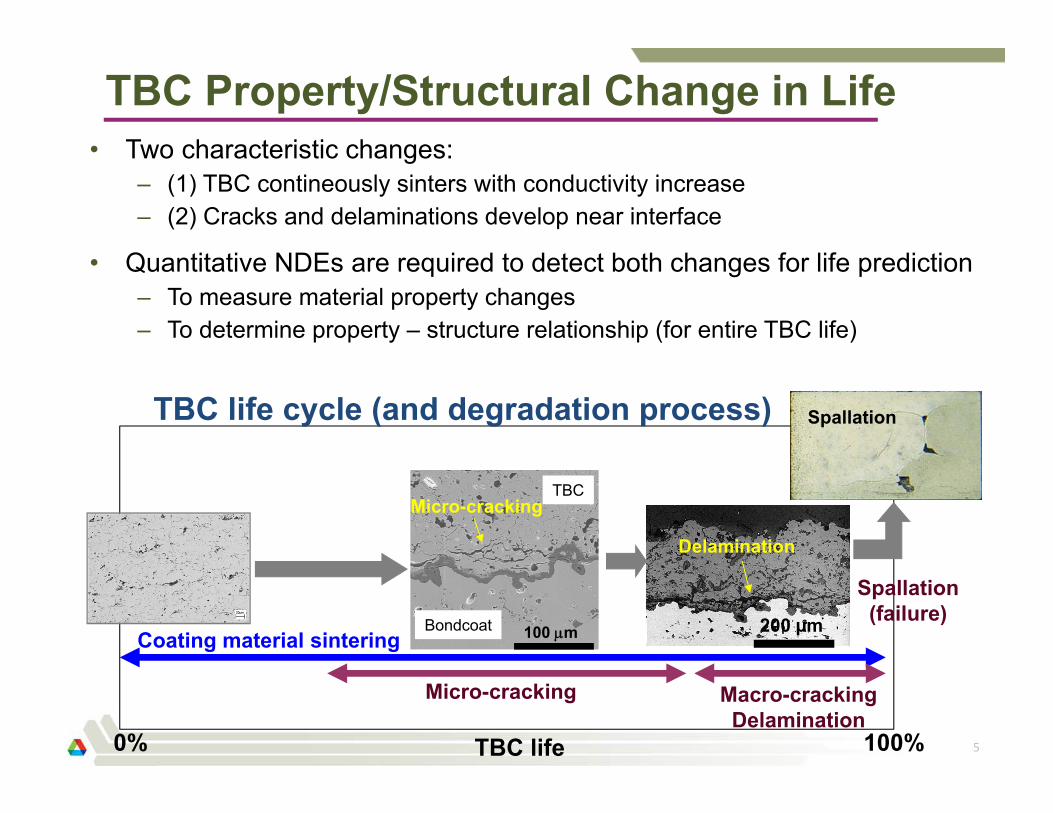
• Two characteristic changes:– (1) TBC contineously sinters with conductivity increase– (2) Cracks and delaminations develop near interface
• Quantitative NDEs are required to detect both changes for life prediction– To measure material property changes– To determine property – structure relationship (for entire TBC life)
Coating material sintering
Micro-cracking Macro-crackingDelamination
0% TBC life 100%
200 µm
Delamination
Spallation(failure)
Micro-cracking
100 m
SpallationTBC life cycle (and degradation process)
Bondcoat
TBC
NDE Applications for TBCs
6
• Many NDE technologies have been studied/used for TBCs: thermal imaging, optical (reflection/scatter, emission, spectroscopy, etc), electrochemical, electromagnetic, ultrasonic, x-ray, etc– Most are not quantitative– Most are not suitable for field application
• NDE for TBC health monitoring and life prediction:– A practical NDE method/model has not been established
• NDE for detection of coating flaws (eg, delaminations, FOD):– Many NDE methods can detect large flaws; those flaws usually appear
near end of TBC life so their detection is of less value– Small and deep flaws are difficult to detect but more important
• NDE for quality control of fabricated TBC components:– Only single-point thickness measurement is used by manufacturer– Current NDE methods are not suitable for TBC property/quality
measurement especially for entire TBC-coated component surface
Objectives of This Project
• Develop and evaluate advanced NDE methods for (1) TBC life prediction and (2) high-resolution detection of coating flaws– (1) For life prediction (quantitative NDE):
• thermal multilayer analysis (MLA) method
– (2) For high-resolution flaw detection• thermal tomography (TT) method
• Develop NDE methods for functional materials (gas-separation membrane, fuel cell, etc)– Synchrotron x-ray CT, thermal tomography
7
Recent NDE Developments
• Continued development of two thermal imaging methods– Thermal multilayer analysis (MLA) for TBC life prediction
• Validation of MLA measurement accuracy for TBCs• Surface treatment (black paint) material evaluation• Development of theoretical models for (1) translucent TBCs and (2)
double-layer TBCs• Evaluation for testing industrial components
– Thermal tomography method (3D TT imaging)• Continued development of new algorithm for high-resolution imaging
• Continued evaluation of thermal imaging NDE methods for TBC life prediction– Collaborations with Siemens and Stony Brook Univ.
8
Presentation Topics
9
• Development and application of multilayer analysis MLA method– Validation of MLA measurement accuracy– Effect of surface paint on TBC property measurement– Theoretical development for translucent TBCs– Theoretical development for double-layer TBCs– Application for a turbine blade
• NDE for TBC life prediction
Thermal Imaging Multilayer Analysis (MLA) Method
10
One-sided experimental setup
Flash lamp IR camera
Monitor
Turbine blade
Thermal conductivity imaging
0.5 W/m-K 1.4 W/m-K
• MLA method developed at ANL can measure TBC thermal properties:– Two TBC properties: thermal conductivity and heat capacity (or thickness)– The only method suitable for field applications (and fully automated)– The only method for imaging entire component surface– Paper accepted by JHT
MLA Measurement Accuracy
11
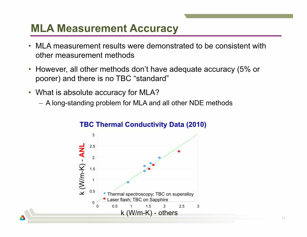
• MLA measurement results were demonstrated to be consistent with other measurement methods
• However, all other methods don’t have adequate accuracy (5% or poorer) and there is no TBC “standard”
• What is absolute accuracy for MLA?– A long-standing problem for MLA and all other NDE methods
0
0.5
1
1.5
2
2.5
3
0 0.5 1 1.5 2 2.5 3
Thermal spectroscopy; TBC on superalloyLaser flash; TBC on Sapphire
k (W/m-K) - others
k (W
/m-K
) -A
NL
TBC Thermal Conductivity Data (2010)
MLA Absolute Accuracy - Demonstrated
12
• MLA accuracy was demonstrated from thermal effusivity e=(kρc)1/2
measurements for various standard bulk materials
• A tape was bonded on bulk material to form a two-layer system– Measured bulk material effusivity e is within 2% of nominal value– This is best demonstrated accuracy among all methods Suitable for TBC life prediction because TBC property change is small (10%)
e, m
easu
red
(W-s
1/2 /m
2 -K
)
0
5000
10000
15000
20000
25000
0 5000 10000 15000 20000 25000
e, nominal (W-s1/2/m2-K)
E. Glycol
GlassWater
SS
CS
Aluminum
Predicted and nominal thermal effusivity e valuesfor various standard materials
Effect of TBC Surface Treatment
13
• Current thermal-imaging model is for opaque coatings (eg, metallic)
• TBC is translucent, needs surface treatment to make it opaque– Common method: apply a thin graphite-based paint on TBC surface
(which can be easily burn off at a low temperature)
• In collaboration with Dr. Cernuschi and Dr. Bison of Italy, effect of surface treatment on TBC property measurement was evaluated
– Three different graphite paints– Three type TBCs: APS, EB-PVD, PS-PVD– Graphite layer did not affect measured TBC thermal diffusivity– A paper was submitted to a journal
Thermal properties
Test methods
Thermal Imaging for Translucent TBCs
14
• A method for translucent TBC property measurement is needed– Because it is usually not desirable to paint a TBC part black
• Difficulty: large optical property changes over thermal imaging wavelength bands
• No theoretical model for flash thermal imaging at present– Exp. data for “opaque” and translucent TBC are significantly different
From: Wahiduzzaman & Morel, ORNL Report, 1992
TBC optical properties
Flashheatingband
IRimaging
band
-1.25
-1.00
-0.75
-0.50
-0.25
0.00
-7 -6 -5 -4 -3 -2 -1 0 1 2
L=0.36mm
Thermal imaging data for “opaque” and translucent TBC
Opaque TBCTranslucent TBC
d(lnT)d(lnt)
d(lnq)d(lnt)
lnt
Theoretical Modeling for Translucent TBCs
15
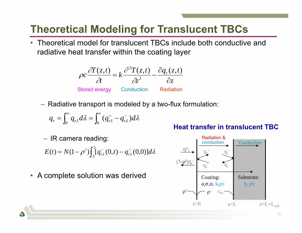
• Theoretical model for translucent TBCs include both conductive and radiative heat transfer within the coating layer
z=Lz=0 z=L+Lsub
Coating:a,,n, k,c
Substrate:k, c
qor
o i
qr+
qr-
qr+
qr-
bc
Radiation &conduction Conduction
(1-i)qr-
Heat transfer in translucent TBC
ztzq
ztzTk
ttzTc r
),(),(),(
2
2
00
)( dqqdqq rrrr
5
3)]0,0(),0([)1()( dqtqNtE rr
i
Stored energy Conduction Radiation
– Radiative transport is modeled by a two-flux formulation:
– IR camera reading:
• A complete solution was derived
Preliminary Results for A Translucent TBC
16
k (W/m-K) ρc (J/cm3-K)
Tran
sluc
ent
Opa
que
1 2.5 1.5 3.5
Predicted thermal conductivity k and heat capacity ρc images for a TBC sample at translucent and “opaque” conditions
• Predicted properties for translucent TBC are consistent with those of “opaque” TBC (for the same TBC sample)
• A paper is being prepared
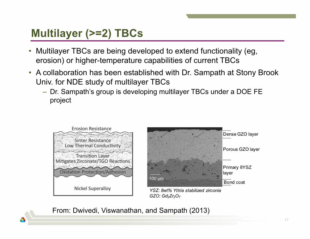
Multilayer (>=2) TBCs
17
From: Dwivedi, Viswanathan, and Sampath (2013)
• Multilayer TBCs are being developed to extend functionality (eg, erosion) or higher-temperature capabilities of current TBCs
• A collaboration has been established with Dr. Sampath at Stony Brook Univ. for NDE study of multilayer TBCs
– Dr. Sampath’s group is developing multilayer TBCs under a DOE FE project
Thermal Imaging for Double-Layer TBCs
18
• Many double-layer TBCs or coatings are of interests
• Initial effort was on measuring 2-layer-averaged TBC property
• Current effort is on measuring coating properties for each layer– MLA method was extended to 2-layer coating systems– Preliminary tests were conducted – data need verification
Thermal effusivity of YSZ in double-layer TBC is much lower that that in single-layer TBC?
5 mm
Substrate
Substrate
YSZ
LZO
YSZ
Low High
TBC Property Measurement for a Turbine Blade
20
TBC: ~0.25mm thick
1000 2000 W-s1/2/m2-K
Thermal effusivity image
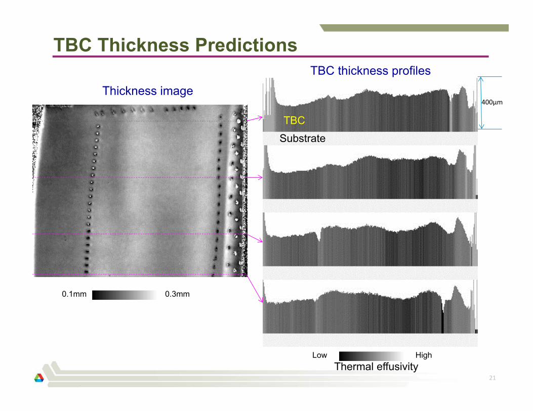
TBC Thickness Predictions
21
Thickness image400µm
TBCSubstrate
TBC thickness profiles
0.1mm 0.3mm
Low HighThermal effusivity
Metallic coating property/thickness prediction
22
Substrate
Coating
Low High
Thermal effusivity
Coating thickness profile
Presentation Topics
23
• Development and application of multilayer analysis MLA method– Validation of MLA measurement accuracy– Effect of surface paint on TBC property measurement– Theoretical development for translucent TBCs– Theoretical development for double-layer TBCs– Application for a turbine blade
• NDE for TBC life prediction– Crack/delamination progression
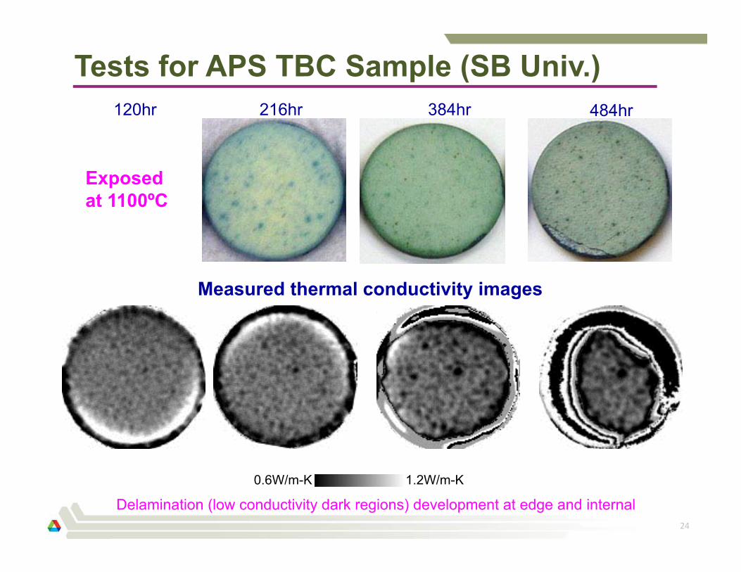
Tests for APS TBC Sample (SB Univ.)
24
384hr216hr120hr
Delamination (low conductivity dark regions) development at edge and internal
0.6W/m-K 1.2W/m-K
484hr
Measured thermal conductivity images
Exposed at 1100ºC
Thermal Tomography Images
25
@0.3mm (interface)
@0.15mm(mid TBCdepth)
@0mm (surface)
384hr216hr120hr 484hr
Dark regions are delaminations
26
Summary
• Thermal imaging multilayer analysis (MLA) method development:– Absolute accuracy of 2% was demonstrated – MLA is ready for TBC studies– Developments for translucent and double-layer TBCs are successful– Successfully applied for testing of industrial components
• NDE for TBC life prediction:– Thermal tomography is successful for detect delamination growth
Planned Future Efforts• Continued evaluation of NDEs for TBC lifetime prediction
– Collaborations with Siemens and Stony Brook Univ.
• Thermal NDE method development for complex TBC systems:– For complex coatings: translucency, multilayer
– Evaluation of measurement accuracy for TBC thermal conductivity, thickness, density/porosity