+ All Categories
Home > Documents > Development of Next Generation Organic Solar Cell KAGAKU 2010-I 3 Development of Next Generation...

Development of Next Generation Organic Solar Cell KAGAKU 2010-I 3 Development of Next Generation...

Date post: 17-Jun-2018
Category:
Upload: leque
View: 215 times
Download: 0 times
Share this document with a friend
12
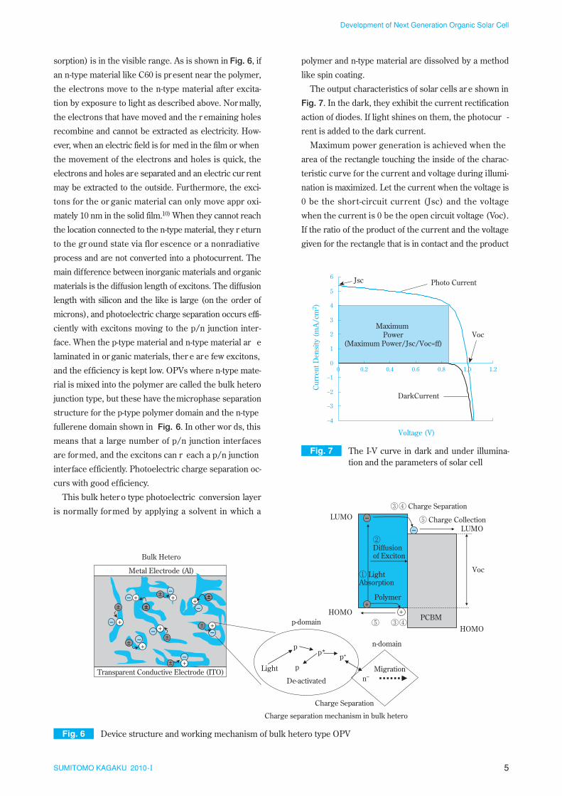
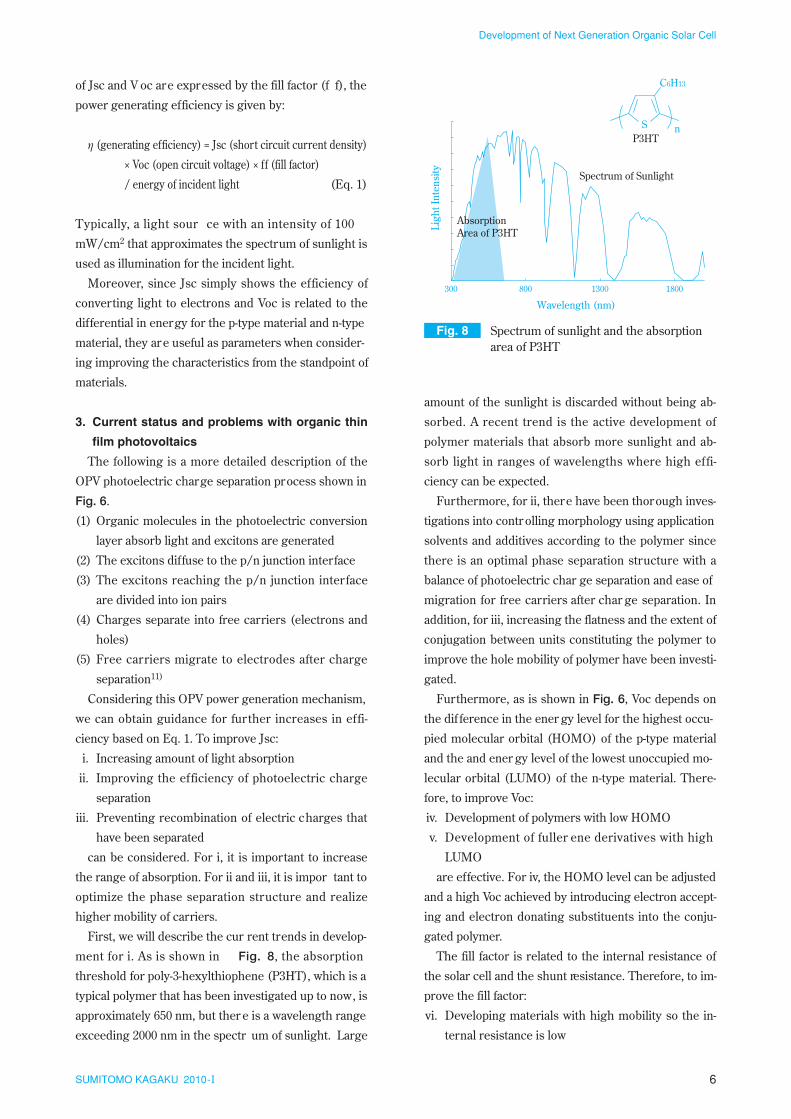
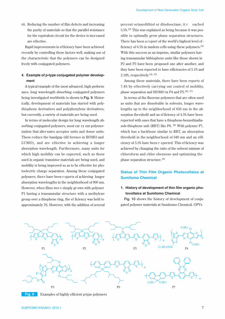
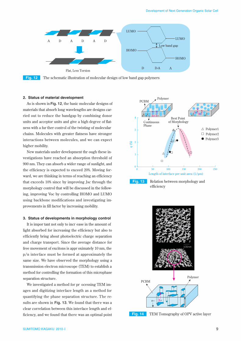
1 SUMITOMO KAGAKU 2010- I Introduction With the recent increase in awareness of the prob- lems of measur es for global war ming and the exhaust- ing of natural r esources, solar cells have attracted worldwide attention as the trump card for solving these problems. Moving forward, they are predicted to be a significant global market exceeding 10 trillion yen in 2020, but we need a scenario for dissemination that makes the costs for power generation using solar cells lower than commer cial power costs. However , the cost of generating power using current solar cells is more expensive than commercial power generation, and the current situation is one where dissemination is happen- ing because of gover nment subsidies. The mainstr eam solar cells ar e cur rently inorganic solar cells like those made of silicon. Since they are manufactured by high temperature and vacuum processes and have a large number of associated par ts, cost r eductions have been slow. Furthermore, since the modules are very heavy, dissemination to homes has been limited because of in- stallation costs and limits on the houses where installa- tion is possible. Thin film or ganic photovoltaics (abbr eviated OPV in the following) are a new generation of solar cells for overcoming these disadvantages of inor ganic solar cells. As is shown in Fig. 1, OPVs are similar to the polymer light-emitting diodes (PLEDs) that Sumitomo Chemical has put ef fort into developing in ter ms of the structure of the device, but the dir ection of operation is reversed. PLEDs generate light from electricity, but OPVs are devices that extract electricity with exposur e to the sun. The main materials for these devices are conjugated polymers. Since high temperature manufac- turing processes are not used, plastic substrates can be used, and a common feature is the ease of making them flexible. Furthermore, if the featur es of manufacturing by ap- plication and printing ar e used, a r oll to r oll processing can be employed as a manufacturing method. Large Development of Next Generation Organic Solar Cell Sumitomo Chemical Co., Ltd. Ohnishi Fellow Laboratory Kunihito MIYAKE Yasunori UETANI Takahiro SEIKE Takehito KATO Kenichiro OYA Tsukuba Research Laboratory Ken YOSHIMURA Fellow Toshihiro OHNISHI Organic photovoltaic, OPV, cells have been attracted much attention for next generation solar cells. OPV is based on the same technology as polymer light-emitting diodes, PLED, which has been developed intensively for TV application at Sumitomo Chemical Co., Ltd. Many PLED-related materials and device fabrication processes can accelerate the development of OPV technology. Although very high efficiency of 6.5% has already been achieved, the efficiency of more than 10% is necessary for the commercialization of OPV. In order to achieve this goal, a new class of low band gap polymer has successfully been prepared together with morphology controlling methods of an active layer of OPV. In this paper, we report the present status of OPV research at Sumitomo Chemical Co., Ltd. as well as worldwide research. This paper is translated fr om R&D Repor t, “SUMITOMO KAGAKU”, vol. 2010- I.
Transcript

1SUMITOMO KAGAKU 2010-I

Introduction

With the recent increase in awareness of the prob-

lems of measur es for global war ming and the exhaust-

ing of natural r esources, solar cells have attracted

worldwide attention as the trump card for solving these

problems. Moving forward, they are predicted to be a

significant global market exceeding 10 trillion yen in

2020, but we need a scenario for dissemination that

makes the costs for power generation using solar cells

lower than commercial power costs. However, the cost

of generating power using current solar cells is more

expensive than commercial power generation, and the

current situation is one where dissemination is happen-

ing because of gover nment subsidies. The mainstr eam

solar cells are currently inorganic solar cells like those

made of silicon. Since they are manufactured by high

temperature and vacuum processes and have a large

number of associated par ts, cost r eductions have been

slow. Furthermore, since the modules are very heavy,

dissemination to homes has been limited because of in-

stallation costs and limits on the houses where installa-

tion is possible.

Thin film or ganic photovoltaics (abbr eviated OPV in

the following) are a new generation of solar cells for

overcoming these disadvantages of inor ganic solar

cells. As is shown in Fig. 1, OPVs are similar to the

polymer light-emitting diodes (PLEDs) that Sumitomo

Chemical has put ef fort into developing in ter ms of the

structure of the device, but the direction of operation is

reversed. PLEDs generate light from electricity, but

OPVs are devices that extract electricity with exposur e

to the sun. The main materials for these devices are

conjugated polymers. Since high temperature manufac-

turing processes are not used, plastic substrates can be

used, and a common feature is the ease of making them

flexible.

Furthermore, if the featur es of manufacturing by ap-

plication and printing are used, a roll to roll processing

can be employed as a manufacturing method. Large

Development of Next Generation Organic Solar Cell

Sumitomo Chemical Co., Ltd.

Ohnishi Fellow Laboratory

Kunihito MIYAKE

Yasunori UETANI

Takahiro SEIKE

Takehito KATO

Kenichiro OYA

Tsukuba Research Laboratory

Ken YOSHIMURA

Fellow

Toshihiro OHNISHI

Organic photovoltaic, OPV, cells have been attracted much attention for next generation solar cells. OPV isbased on the same technology as polymer light-emitting diodes, PLED, which has been developed intensively forTV application at Sumitomo Chemical Co., Ltd. Many PLED-related materials and device fabrication processescan accelerate the development of OPV technology. Although very high efficiency of 6.5% has already beenachieved, the efficiency of more than 10% is necessary for the commercialization of OPV. In order to achieve thisgoal, a new class of low band gap polymer has successfully been prepared together with morphology controllingmethods of an active layer of OPV. In this paper, we report the present status of OPV research at SumitomoChemical Co., Ltd. as well as worldwide research.

This paper is translated fr om R&D Repor t, “SUMITOMO KAGAKU”, vol. 2010- I.

2SUMITOMO KAGAKU 2010-I

Development of Next Generation Organic Solar Cell

cost reductions are then possible using continuous pro-

duction. In addition, since the flexible OPVs are light,

they can easily be installed on houses, and we expect

that they can be supplied at a low cost. Advanced molec-

ular design technology and synthesis technology are

necessary for manufacturing the conjugated polymers

used in OPVs, and raw material makers like Sumitomo

Chemical can easily make use of their strengths. Fur-

thermore, this is a field where Sumitomo Chemical,

which leads the world in PLED material design technol-

ogy and device manufacturing technology, can easily

make use of its technical exper tise. In fact, we ar e the

first worldwide to be successful with an efficiency ex-

ceeding 6% in a single device, 1) and we can brag about

development at the highest level.

However, when we look at things from the standpoint

of making OPVs practical, we are still at the research

and development level compar ed with silicon solar

cells, which are the main current now. Improvements in

both efficiency and durability are necessary. Not only

Sumitomo Chemical, but also the rest of the world is

getting more active in studying these improvements

aimed at making OPVs practical. In this ar ticle, we will

report on the (1) featur es of OPVs, (2) tr ends in devel-

opment worldwide and (3) current status of OPV devel-

opment at Sumitomo Chemical.

Current Situation in Photovoltaic Power Gener-

ation

1. Photovoltaic power generation expected to be

trump card for solving environment problems

Abnormal weather conditions, increases in the level

of the oceans and other problems caused by global

warming ar e intensifying. The pr oblems of global

warming are being taken up as pr oblems for society as

a whole. CO2 and other greenhouse gases are said to be

one of the causes of the global warming problem. Work

on reducing CO2 has started worldwide. Recently, inter-

national targets for reducing greenhouse gases were

determined at COP15, and Cool Earth 50 for halving

the emissions of gr eenhouse gases worldwide by 2050

was proposed for the Post-Kyoto Protocol. Further-

more, even though this is presupposed on the Japanese

government and other countries agreeing, CO2 reduc-

tions have become an extremely important topic with

the setting a target of a 25% reduction from the 1990

greenhouse gas levels by 2020 and the like.

Under these cir cumstances, photovoltaic power gen-

eration is a green energy source that conver ts sunlight

directly into electrical energy and does not produce

CO2. It is one of the technologies that is receiving atten-

tion as a trump card in CO2 reduction. The solar energy

that r eaches the Ear th is immense at 176 trillion

kJ/sec,2) and just an hour of solar energy could cover

the world’s annual energy consumption (11.10 billion

tons (equivalent in oil) in 2007).

However, sunlight has a broad spectrum ranging

from ultraviolet rays to infrar ed rays, and there are fac-

tors, such as limitations to the wavelengths that can be

converted into electricity, the energy density being low

(1 kW/m2 at the mid latitudes) and variability in the

amount of power generated because of night and day as

well as weather, that have prevented dissemination. For

example, to generate the 2 to 3 kWh that is the power

used by a standard household, a surface area of 20 to

30 m2 would be necessar y with a conversion ef ficiency

of 10%. The key to dissemination of photovoltaics is

high efficiency and low cost.

2. Types and features of solar cells

Fig. 2 shows the types of solar cells that are cur-

rently on the market or being developed. There is a pro-

fusion of solar cells now, but the main current among

them at present is silicon solar cells. There are thin film

and crystalline silicon solar cells, and crystalline onesFig. 1 Similarity in device structures and

materials

Conjugated Polymer

LightLight

PLED

OPV

+ ––

+

+

Electrode Electrode

+ ––+Electrode Electrode

C8H17 C8H17

N

3SUMITOMO KAGAKU 2010-I

Development of Next Generation Organic Solar Cell

include single crystal and polycrystal types. High purity

silicon must be used as the raw material for cr ystalline

solar cells, and high temperatur e processes are neces-

sary in the production process for the raw materials

and ingots. Thin-film solar cells are manufactured by

plasma CVD using silane gas. The thickness required

for thin film solar cells is several microns, less than one-

tenth of that for crystalline solar cells, but they have

lower efficiency than crystalline solar cells.

Practical applications of thin film solar cells that

make use of compound semiconductors such as copper

indium gallium selenide (CIGS) and CdTe have come

about to eliminate these deficiencies. However, little

progress has been made on cost r eduction for these in-

organic solar cells because high temperature and vac-

uum processes are used, and there is also the use of

materials for which there are limited resources.

On the other hand, dye-sensitized and thin film or-

ganic solar cells have been developed. Dye-sensitized

solar cells are devices where a dye is absorbed into

porous titanium oxide. They convert the energy of light

that is been absorbed by the dye into electrical ener gy.

There have been r eports of ef ficiency exceeding 10%.3)

However, there are problems with liquids leaking since

an iodine solution is used, so they have still not become

practical. Thin film organic solar cells are roughly di-

vided into small molecule and polymer types depending

on the p-type material used. Light is converted into

electricity by using both p-type and n-type materials in a

mixture or in laminations. The trend has been for devel-

opment of polymer materials to be more active than

that for smaller molecules, and improvement in the effi-

ciency of polymer systems is moving for ward. In addi-

tion, a fuller ene derivative (PCBM), which is an n-type

material, is mixed in by solution in polymer systems,

and a feature of these is being able to manufactur e the

solar cells by application or printing. High-temperatur e

processes are unnecessar y, and it is easy to use a plas-

tic substrate to make them flexible. Since cost reduc-

tions are possible using a r oll to roll process, these are

attracting attention as being the closest thing for the

next generation of solar cells. Development of uses in

mobile equipment, vehicles, etc., making use of fea-

tures not available in conventional solar cells, such as

light weight and flexibility, are being investigated.

3. Scenario for dissemination of solar cells and

market

The key to widespr ead dissemination of solar power

generation is the reduction of generating costs. The

New Energy and Industrial Technology Development

Organization (NEDO) has planned for a dissemination

scenario known as PV2030+ ( Fig. 3).4) In this scenario,

mass dissemination is achieved by lowering the cost of

solar power generation to the equivalent of home elec-

trical utility rates, commercial electrical utility rates and

general-purpose electrical utility rates. Organic photo-

voltaics are a new generation of solar cells for overcom-

ing these disadvantages of inorganic solar cells.

Under these circumstances, the potential need for

solar power generation is great, and as is shown in Fig.

4, there are expectations of rapid growth with the scale

of the market exceeding 80 GW and ¥10 trillion by

2020.5)

Fig. 2 The classification of materials for solar cells

Solar Cell

Organic

Crystalline

Single Crystal(GaAs)

Thin Film

Thin Film

Thin Film(CIGS, CdTe)

Dye-sensitized

Single CrystalCoventional Application: Roof-top

New Application: Car, Wall, Window, Mobile etc.

Polycrystal(Most Popular)Silicon

CompoundSemiconductor

Inorganic

4SUMITOMO KAGAKU 2010-I

Development of Next Generation Organic Solar Cell

Trends in the Development of Thin Film Organic

Photovoltaics

1. History

Calvin et al. discover ed in 1958 that shining light on

organic materials such as magnesium porphyrin caused

an electrical current to arise. Unceasing efforts were

put in to applications of this in solar cells, but nothing

with a high efficiency was discovered. Before the devel-

opment of or ganic LEDs by Kodak’s T ang in 1986, the

highest efficiency reported for solar cells with lamina-

tions of or ganic layers was appr oximately 1%. W ith the

advent of or ganic LEDs, the inter est in solar cells that

use organic materials increased worldwide.6)

On the other hand, in 1992, Osaka University’s

Yoshino discovered that a photocurrent could be ob-

tained with good ef ficiency by mixing polythiophene or

polyphenylene (jointly with Sumitomo Chemical),

which are known to be electrically conductive poly-

mers, with fullerene (C60).7) As is shown in Fig. 5, this

phenomenon is explained by electrons moving to the

C60 after the conjugated polymer is excited by illumina-

tion with light. Holes (positive char ges) move into the

polymer chain, and the electrons move into the C60,

creating an efficient photoelectric charge separation.

With this discovery, development of solar cells using

conjugated polymers began.8) With the development of

fullerene derivatives that are soluble in solvents in 1995,

the ef ficiency was incr eased and r eached appr oxi-

mately 3%.9)

2. Thin Film Organic Photovoltaics

Conjugated polymers have pi electr ons and ar e typi-

cally p-type materials. Their bandgap (range of light ab-

Fig. 3 PV2030+ scenario for future growth of PV power generation 4)

Fig. 4 Market size of solar cells[Data from reference 5)]

0

2000

4000

6000

8000

10000

12000

0

20000

40000

60000

80000

100000

2007 2008 2009 2010 2011 2012 2015 2020

Year

Mar

ket S

ize

(Bill

ion¥

)

Mar

ket S

ize

(MW

)

Value Basis (Billion¥)Power Basis (MW)

Fig. 5 Photoconduction in the blend of PPV and C60 and schematic illustration of the mechanism of generation of photocurrent

++ ––

Electron Transfer

1086420

Concentration of C60 (mol%)

Exciton generation

Light

RO-PPV

C60

10–10

10–9

10–8

10–7

Phot

ocon

duct

ion

Inte

nsity

(arb

.uni

ts)

RO-PPV/C60

nRO

OR

5

Development of Next Generation Organic Solar Cell

SUMITOMO KAGAKU 2010-I

polymer and n-type material are dissolved by a method

like spin coating.

The output characteristics of solar cells ar e shown in

Fig. 7. In the dark, they exhibit the current rectification

action of diodes. If light shines on them, the photocur -

rent is added to the dark current.

Maximum power generation is achieved when the

area of the rectangle touching the inside of the charac-

teristic curve for the current and voltage during illumi-

nation is maximized. Let the current when the voltage is

0 be the short-circuit current (Jsc) and the voltage

when the current is 0 be the open circuit voltage (Voc).

If the ratio of the product of the current and the voltage

given for the rectangle that is in contact and the product

Fig. 6 Device structure and working mechanism of bulk hetero type OPV

Metal Electrode (Al)

Transparent Conductive Electrode (ITO)

– +

+ +

+

+

+

+–

±

±±±

±

±

±

±

±

Bulk Hetero

+

± –

Charge separation mechanism in bulk hetero

p*p

Light p

De-activated

p+

n–

Charge Separation

p-domain

n-domain

Migration

+

+

1 Light Absorption

2Diffusionof Exciton

34 Charge Separation

5 Charge Collection

5 34

Polymer

PCBM

LUMO

HOMO

LUMO

HOMO

Voc

Fig. 7 The I-V curve in dark and under illumina-tion and the parameters of solar cell

Maximum Power

(Maximum Power/Jsc/Voc=ff)

−4

−3

−2

−1

0

1

2

3

4

5

6

0 0.2 0.4 0.6 0.8 1.0 1.2

Voltage (V)

Cur

rent

Den

sity

(m

A/c

m2 )

Jsc

Voc

DarkCurrent

Photo Current

sorption) is in the visible range. As is shown in Fig. 6, if

an n-type material like C60 is present near the polymer,

the electrons move to the n-type material after excita-

tion by exposure to light as described above. Nor mally,

the electrons that have moved and the r emaining holes

recombine and cannot be extracted as electricity. How-

ever, when an electric field is for med in the film or when

the movement of the electrons and holes is quick, the

electrons and holes are separated and an electric cur rent

may be extracted to the outside. Furthermore, the exci-

tons for the or ganic material can only move appr oxi-

mately 10 nm in the solid film.10) When they cannot reach

the location connected to the n-type material, they r eturn

to the gr ound state via flor escence or a nonradiative

process and are not converted into a photocurrent. The

main difference between inorganic materials and organic

materials is the diffusion length of excitons. The diffusion

length with silicon and the like is large (on the order of

microns), and photoelectric charge separation occurs effi-

ciently with excitons moving to the p/n junction inter-

face. When the p-type material and n-type material ar e

laminated in or ganic materials, ther e are few excitons,

and the efficiency is kept low. OPVs where n-type mate-

rial is mixed into the polymer are called the bulk hetero

junction type, but these have the microphase separation

structure for the p-type polymer domain and the n-type

fullerene domain shown in Fig. 6. In other wor ds, this

means that a large number of p/n junction interfaces

are formed, and the excitons can r each a p/n junction

interface efficiently. Photoelectric charge separation oc-

curs with good efficiency.

This bulk heter o type photoelectric conversion layer

is normally formed by applying a solvent in which a

6

Development of Next Generation Organic Solar Cell

SUMITOMO KAGAKU 2010-I

amount of the sunlight is discarded without being ab-

sorbed. A recent trend is the active development of

polymer materials that absorb more sunlight and ab-

sorb light in ranges of wavelengths where high effi-

ciency can be expected.

Furthermore, for ii, there have been thorough inves-

tigations into contr olling morphology using application

solvents and additives according to the polymer since

there is an optimal phase separation structure with a

balance of photoelectric char ge separation and ease of

migration for free carriers after char ge separation. In

addition, for iii, increasing the flatness and the extent of

conjugation between units constituting the polymer to

improve the hole mobility of polymer have been investi-

gated.

Furthermore, as is shown in Fig. 6, Voc depends on

the dif ference in the ener gy level for the highest occu-

pied molecular orbital (HOMO) of the p-type material

and the and ener gy level of the lowest unoccupied mo-

lecular orbital (LUMO) of the n-type material. There-

fore, to improve Voc:

iv. Development of polymers with low HOMO

v. Development of fuller ene derivatives with high

LUMO

are effective. For iv, the HOMO level can be adjusted

and a high Voc achieved by introducing electron accept-

ing and electron donating substituents into the conju-

gated polymer.

The fill factor is related to the internal resistance of

the solar cell and the shunt resistance. Therefore, to im-

prove the fill factor:

vi. Developing materials with high mobility so the in-

ternal resistance is low

of Jsc and V oc are expressed by the fill factor (f f), the

power generating efficiency is given by:

η (generating efficiency) = Jsc (short circuit current density)

× Voc (open circuit voltage) × ff (fill factor)

/ energy of incident light (Eq. 1)

Typically, a light sour ce with an intensity of 100

mW/cm2 that approximates the spectrum of sunlight is

used as illumination for the incident light.

Moreover, since Jsc simply shows the efficiency of

converting light to electrons and Voc is related to the

differential in energy for the p-type material and n-type

material, they are useful as parameters when consider-

ing improving the characteristics from the standpoint of

materials.

3. Current status and problems with organic thin

film photovoltaics

The following is a more detailed description of the

OPV photoelectric charge separation process shown in

Fig. 6.

(1) Organic molecules in the photoelectric conversion

layer absorb light and excitons are generated

(2) The excitons diffuse to the p/n junction interface

(3) The excitons reaching the p/n junction interface

are divided into ion pairs

(4) Charges separate into free carriers (electrons and

holes)

(5) Free carriers migrate to electrodes after charge

separation11)

Considering this OPV power generation mechanism,

we can obtain guidance for further increases in effi-

ciency based on Eq. 1. To improve Jsc:

i. Increasing amount of light absorption

ii. Improving the efficiency of photoelectric charge

separation

iii. Preventing recombination of electric charges that

have been separated

can be considered. For i, it is important to increase

the range of absorption. For ii and iii, it is impor tant to

optimize the phase separation structure and realize

higher mobility of carriers.

First, we will describe the cur rent trends in develop-

ment for i. As is shown in Fig. 8, the absorption

threshold for poly-3-hexylthiophene (P3HT), which is a

typical polymer that has been investigated up to now, is

approximately 650 nm, but ther e is a wavelength range

exceeding 2000 nm in the spectr um of sunlight. Large

Fig. 8 Spectrum of sunlight and the absorption area of P3HT

300 800 1300 1800

Wavelength (nm)

Ligh

t Int

ensi

ty

AbsorptionArea of P3HT

Spectrum of Sunlight

P3HTS

C6H13

n

7

Development of Next Generation Organic Solar Cell

SUMITOMO KAGAKU 2010-I

percent octanedithiol or diiodooctane, it r eached

5.5%.12) This was explained as being because it was pos-

sible to optimally grow phase separation structures.

There has been a report of the world’s highest level ef -

ficiency of 6.5% in tandem cells using these polymers.13)

With this success as an impetus, similar polymers hav-

ing transannular bithiophene units like those shown in

P2 and P3 have been proposed one after another, and

they have been reported to have efficiencies of 5.1% and

2.18%, respectively.14), 15)

Among these materials, there have been reports of

7.4% by ef fectively carrying out control of mobility,

phase separation and HOMO in P4 and P5.16), 17)

In terms of the fluorene polymers that are often used

as units that are dissolvable in solvents, longer wave-

lengths up to the neighborhood of 650 nm in the ab-

sorption threshold and an ef ficiency of 4.5% have been

reported with ones that have a thiophene-benzothiadia-

zole-thiophene unit (RBT) like P6. 18) With polymer P7,

which has a backbone similar to RBT, an absorption

threshold in the neighborhood of 640 nm and an effi-

ciency of 5.5% have been r eported. This ef ficiency was

achieved by changing the ratio of the solvent mixture of

chloroform and chlor obenzene and optimizing the

phase separation structure.19)

Status of Thin Film Organic Photovoltaics at

Sumitomo Chemical

1. History of development of thin film organic pho-

tovoltaics at Sumitomo Chemical

Fig. 10 shows the history of development of conju-

gated polymer materials at Sumitomo Chemical. OPVs

vii. Reducing the number of film defects and increasing

the purity of materials so that the parallel resistance

for the equivalent circuit for the device is increased

are effective.

Rapid improvements in ef ficiency have been achieved

recently by controlling these factors well, making use of

the characteristic that the polymers can be designed

freely with conjugated polymers.

4. Example of p-type conjugated polymer develop-

ment

A typical example of the most advanced, high perform-

ance, long wavelength absorbing conjugated polymers

being investigated worldwide is shown in Fig. 9. Histor-

ically, development of materials has started with poly-

thiophene derivatives and polyphenylene derivatives,

but currently, a variety of materials are being used.

In terms of molecular design for long wavelength ab-

sorbing conjugated polymers, most car ry out polymer-

ization that alter nates acceptor units and donor units.

These reduce the bandgap (dif ference in HOMO and

LUMO), and are ef fective in achieving a longer

absorption wavelength. Furthermore, many units for

which high mobility can be expected, such as those

used in organic transistor materials are being used, and

mobility is being improved so as to be effective for pho-

toelectric charge separation. Among these conjugated

polymers, there have been r eports of achieving longer

absorption wavelengths in the neighborhood of 900 nm.

However, when films wer e simply gr own with polymer

P1 having a transannular structure with a methylene

group over a thiophene ring, the ef ficiency was held to

approximately 2%. However, with the addition of several

Fig. 9 Examples of highly efficient p-type polymers

SSN

SN

P1

SS

Si

NS

N

P2

SS

N

NS

NS S

P3

S SC8H17 C8H17

NN

P7

n n n

n

S

S

S

S

C12H25OOC

O

O

C8H17

C8H17

P4

n

NS

NS S

P6

nS

S

S

SF

O

O

P5

n

OO

8

Development of Next Generation Organic Solar Cell

SUMITOMO KAGAKU 2010-I

have evolved from research and development on con-

ductive polymers as have PLEDs. Development was

started on conductive polymers in 1981, but since up to

that time conjugated polymers were insoluble in sol-

vents, development was carried out placing importance

on their forming properties. Since the polyphenylene

vinylene that was developed could be molded in a film,

its semiconductor characteristics were a field other

than conductivity that was interesting. Investigations

into applications in photoelectric fields also started

since it could be molded into a film. Out of this, organic

LEDs, organic transistors and photoelectric conversion

devices were discovered. From this histor y it can also

be said that PLED and OPV materials have the same

technical foundations. PLED materials are materials

that show a strong fluorescence in visible light, but

polymer OPV materials are materials that exhibit ab-

sorption from visible light to the infrar ed range. There-

fore, a different molecular design is necessary for the

structure of the monomers that ar e used, but there is a

great deal of commonality in the polymerization meth-

ods and pr oduction of devices. A gr eat deal of technol-

ogy, such as knowledge about the cor relation between

the functions being fostered in PLED material develop-

ment and molecular design, techniques for uniform for-

mation of organic films and techniques for synthesizing

highly pure polymer materials, has accumulated, and

this is also a driving for ce in the development of high-

performance OPVs at Sumitomo Chemical.

Based on this technology, Sumitomo Chemical has

been the first worldwide to be successful in exceeding

6% (Sumitomo Chemical measurements, Fig. 11). In ad-

dition, precise measurements of efficiency were made

jointly with the National Institute of Advanced Indus-

trial Science and T echnology (AIST), and an ef ficiency

close to this has been confirmed.

Currently, along with radically r eassessing materials

to achieve ef ficiencies of 10% or gr eater, which ar e the

target for practicality, we are carefully examining Jsc

and Voc as they relate to ef ficiency, fill factor and mate-

rial structure, and the relationship between purity and

microphase separation structure. We are carrying out

investigations into increased efficiency based on this

knowledge and the r esults of analyzing the mecha-

nisms. Furthermore, to get an early grasp on the pr ob-

lems for making practical OPVs, we are carrying out

investigations into production processes while making

use of knowledge regarding PLED device development.

Fig. 11 The result of efficiency of OPV measured at Sumitomo Chemical

0

2

4

6

8

10

12

14

0 0.2 0.4 0.6 0.8 1

Voltage (V)

Cur

rent

Den

sity

(mA/

cm2 )

η=6.5%

Fig. 10 History of development of conjugated polymer at Sumitomo Chemical

OTFT

OPV

�Oriented PPV : 104S · cm–1

PPV

PTV

RO-PPV

PF

Conjugated Polymer

Conductivity

PLED(’89 ~ )

– Molecular Weight– Copolymerization

– Processability Solubility

Semiconductivity

PPV-derivatives ’81-’91 : National PJ

’86-now

RO-PPV+C60

Conjugated Polymers for Electronics

n

n

OR

RO

S

C8H17 C8H17

9

Development of Next Generation Organic Solar Cell

SUMITOMO KAGAKU 2010-I

2. Status of material development

As is shown in Fig. 12, the basic molecular designs of

materials that absorb long wavelengths are designs car-

ried out to reduce the bandgap by combining donor

units and acceptor units and give a high degree of flat-

ness with a fur ther control of the twisting of molecular

chains. Molecules with greater flatness have stronger

interactions between molecules, and we can expect

higher mobility.

New materials under development thr ough these in-

vestigations have reached an absorption threshold of

900 nm. They can absorb a wider range of sunlight, and

the efficiency is expected to exceed 20%. Moving for-

ward, we are thinking in terms of reaching an efficiency

that exceeds 10% since by improving Jsc through the

morphology control that will be discussed in the follow-

ing, improving Voc by controlling HOMO and LUMO

using backbone modifications and investigating im-

provements in fill factor by increasing mobility.

3. Status of developments in morphology control

It is impor tant not only to incr ease in the amount of

light absorbed for increasing the efficiency but also to

efficiently bring about photoelectric charge separation

and charge transport. Since the average distance for

free movement of excitons is appr oximately 10 nm, the

p/n interface must be formed at approximately the

same size. We have observed the morphology using a

transmission electron microscope (TEM) to establish a

method for controlling the formation of this microphase

separation structure.

We investigated a method for pr ocessing TEM im-

ages and digitizing interface length as a method for

quantifying the phase separation structure. The re-

sults are shown in Fig. 13. We found that there was a

clear correlation between this interface length and ef-

ficiency, and we found that there was an optimal point

Fig. 12 The schematic illustration of molecular design of low band gap polymers

D D-A A

HOMO

HOMO

LUMO

LUMO

Low band gap

Flat, Less Torsion

A D A D A D

Fig. 14 TEM Tomography of OPV active layer

PCBM

e– h+

Polymer

Fig. 13 Relation between morphology and efficiency

0

1

2

3

4

0 50 100 150 200 250

Polymer1

Polymer2Polymer3

Best Point of Morphology

η (

%)

Length of interface per unit area (1/µm)

Continuous Phase

PolymerPCBM

h+ h+ h+x

h+x

e–e– e– e–

10

Development of Next Generation Organic Solar Cell

SUMITOMO KAGAKU 2010-I

for inter face length. The for mation of the inter face is

insufficient when the inter face length is too shor t, so

the charge separation efficiency is poor. The interface

formation is suf ficient when the interface length is

too large, but it is thought that the free carrier move-

ment deteriorates because of insufficient formation of

the continuous phase. Fig. 14 shows a TEM morphol-

ogy image of observations in the neighborhood of the

optimal point for interface length. As predicted, we

found that an island structure of microphase separa-

tion is seen, and continuous phases for each of the do-

mains ar e for med in the dir ection of the film

thickness. An ideal morphology is formed. We think

that interface length is suitable as an indicator of mor-

phology.

Next, we investigated the establishment of a mor-

phology control method using interface length. Since

the microphase separation structure is thought to be

related to the solubility of the polymers that ar e p-type

material and the n-type material (PCBM) in solvents,

we investigated the relationship between the solvents

having various solubility parameters (SP value) and in-

terface length. We found that the closer the SP value of

the solvent used was to PCBM, the smaller the phase

separation structure was and the longer the interface

length. This was estimated to be the primary cause of

precipitation of the p-type molecules fr om the solution.

In this manner, we were able to establish a method for

controlling the morphology using solvents having vari-

ous SP values.

As a result of investigating low band gap polymers

and morphology control methods as described above,

we achieved the world’s highest values for a single de-

vice with Jsc at 16 mA/cm2 and an efficiency of approxi-

mately 7%.

4. Assurance of reliability

Besides the conversion efficiency, assurance of relia-

bility is also impor tant for making OPVs practical. As a

step toward this, we have begun measurements of life

with outdoor exposure and continuous exposure to

light indoors using solar simulators with systems that

make use of typical p-type polymers PCBM (Fig. 15).

The horizontal axis is total light intensity. There are dif-

ferent results for the rate of reduction in efficiency in-

doors and outdoors, and after one month of outdoor

exposure we couldn’t find that there is a clear reduction

in efficiency. On the other hand, in the tests of continu-

ous exposur e indoors, we found r eductions in ef fi-

ciency due to a r eduction in Jsc in par ticular. We

measured the infrared absorption spectrum to examine

the chemical changes in the material due to exposure

to light, but we saw no changes that could be detected.

Therefore, we presumed that the causes of deteriora-

tion were dif ferences in the phase separation str ucture

and changes in the electr ode inter faces. The investiga-

tion has just gotten star ted, but the cur rent value flow-

ing is on about the same or der as PLEDs, and it is

presumed that most of the deterioration mechanisms

are similar in that they pass thr ough the excited state.

Therefore, we think that we can quickly impr ove relia-

bility if we make use of our knowledge of PLEDs.

One of the important problems for assuring reliabil-

ity is that a method for pr edicting the life of OPVs has

not been established. Since it is assumed that the meth-

ods used with silicon solar cells for the materials and

power generation principles used cannot be applied as

it is to OPVs, it is important to identify the deterioration

modes peculiar to OPVs and establish new methods for

predicting their life. We plan to accumulate data under

various conditions, such as device structure, elucidate

Fig. 15 Comparison of stability under between indoor and outdoor condition

0

1

2

3

4

5

6

7

0 1000 2000 3000 4000 0 1000 2000 3000 4000

Total Light Intensity (hrs×mW/cm2)

η(%

), J

sc(m

A/c

m2 )

, Voc

(V)

or ff

0

1

2

3

4

5

6

7

Total Light Intensity (hrs×mW/cm2)

η(%

), J

sc(m

A/c

m2 )

, Voc

(V)

or ff

Jsc

η

Vocff

Condition: Outdoor

ff

Voc

η

Jsc

Condition: Indoor

11

Development of Next Generation Organic Solar Cell

SUMITOMO KAGAKU 2010-I

the mechanism of deterioration, establish a life pr edic-

tion method by comparing the life in outdoor exposur e

and accelerated indoor testing and increase a life based

on these.

Future Outlook

Silicon solar cells are widely disseminated, but the

energy produced by power generation using solar cells

is only 0. 1% or less of energy consumed. With the in-

crease in concern for environmental problems, there

are further expectations for the dissemination of solar

cells, but a breakthrough is necessary for replacing

current power generating systems. OPVs are thought

to hold the possibilities for an impor tant breakthrough

in the field of solar cells. In addition to impr oving ef fi-

ciency and assuring r eliability, a key is developing r oll

to roll processes. We are planning to achieve these and

make an early entry into the market.

References

1) Nikkan Kogyo Shinbun, 2009.2.20, p.1

2) Japan Photovoltaic Ener gy Association(JPEA)

homepage, http://www.jpea.gr.jp/11basic01.html

3) M.K. Nazeeruddin, F.D. Angelis, S. Fantacci, A. Sel-

loni, G. V iscardi, P. Liska, S. Ito, B. T akeru and M.

Graetzel, J. Am. Chem. Soc., 127 (48), 16835 (2005).

4) “PV Roadmap 2030 (PV2030+)”, New Ener gy Tech-

nology Development Department, New Energy and

Industrial Technology Development Organization

(2009), p.14.

5) Present Status and Future Outlook of Solar Cell

Technologies and Market 2009, Fuji Keizai (2009),

p.14.

6) C.W.Tang, Appl. Phys. Lett., 48, 183 (1986).

7) K. Yoshino, S. Morita, T. Kawai, H. Araki, X. H. Y in

and A. A. Zakhidov , Synthetic Metals , 56, 2991

(1993).

8) N. S. Sariciftci, L. Smilowitz, A. J. Heeger and F.

Wudl, Science, 258, 1474 (1992).

9) G.Yu, J. Gao, J. C. Hummelen, F. Wudl and A. J.

Heeger, Science, 270, 1789 (1995).

10) Kaku Uehara, Susumu Yoshikawa, “Leading-edge

Technology for Thin Film Organic Photovoltaic

Cell”, CMC Publishing Co., Ltd. (2005), p.75.

11) Kaku Uehara, Susumu Yoshikawa, “Leading-edge

Technology for Thin Film Organic Photovoltaic

Cell”, CMC Publishing Co., Ltd. (2005), p.88.

12) J. Peet, J. Y. Kim, N. E. Coates, W. L. Ma, D. Moses,

A. J. Heeger and G. C. Bazan, Nat. Mater., 6, 497

(2007).

13) J. Y . Kim, K. Lee, N. E. Coates, D. Moses, T .

Nguyen, M. Dante and A. J. Heeger, Science, 317,

222 (2007).

14) J. Hou, H. Chen, S. Zhang, G. Li and Y. Yang, J. Am.

Chem. Soc., 130, 16144 (2008).

15) E. Zhou, M. Nakamura, T . Nishizawa, Y. Zhang, Q.

Wei, K. T ajima, C. Yang and K. Hashimoto, Macro-

molecules, 41, 8302 (2008).

16) L. Yongye, F. Danqin, S. Hae-Jung, Y. Luping, W.

Yue, T. Szu-T ing, L. Gang, J. Am. Chem. Soc ., 131,

56 (2009).

17) Y. Liang, Z. Xu, J. Xia, S. Tsai, Y . Wu, G. Li, C. Ray ,

L. Yu, Adv. Mater. -Early View, DOI: 10.1002/adma.

200903528 (Published Online: 4 Jan 2010), (cited 9

Apr 2010).

18) M. Chen, J. Hou, Z. Hong, G. Yang, S. Sista, L. Chen

and Y. Yang, Adv. Mater., 21, 4238 (2009).

19) D. Kitazawa, N. W atanabe, S. Y amamoto and J.

Tsukamoto, Appl. Phys. Lett., 95, 053701 (2009).

12

Development of Next Generation Organic Solar Cell

SUMITOMO KAGAKU 2010-I

P R O F I L E

Kunihito MIYAKE

Sumitomo Chemical Co., Ltd.Ohnishi Fellow LaboratorySenior Research Associate

Kenichiro OYA

Sumitomo Chemical Co., Ltd.Ohnishi Fellow LaboratoryResearcher

Yasunori UETANI

Sumitomo Chemical Co., Ltd.Ohnishi Fellow LaboratorySenior Research Specialist

Ken YOSHIMURA

Sumitomo Chemical Co., Ltd.Tsukuba Research LaboratoryResearch Associate

Takahiro SEIKE

Sumitomo Chemical Co., Ltd.Ohnishi Fellow LaboratoryResearch Associate,Doctor of Engineering

Toshihiro OHNISHI

Sumitomo Chemical Co., Ltd.FellowDoctor of Engineering

Takehito KATO

Sumitomo Chemical Co., Ltd.Ohnishi Fellow LaboratoryResearcher, Doctor of Engineering


Recommended