+ All Categories
Home > Documents > Development of NOx Adsorber System for Dodge Ram 2007 ...

Development of NOx Adsorber System for Dodge Ram 2007 ...

Date post: 23-Mar-2022
Category:
Upload: others
View: 2 times
Download: 0 times
Share this document with a friend
14
Development of a NOx Adsorber System for Dodge Ram 2007 Heavy Duty Pickup Truck Aleksey Yezerets , Neal W. Currier, Bradlee J. Stroia, Junhui Li Cummins Inc. Howard Hess, Haiying Chen, Andy Walker Johnson Matthey
Transcript

Development of a NOx Adsorber System

for Dodge Ram 2007 Heavy Duty Pickup Truck

Aleksey Yezerets, Neal W. Currier, Bradlee J. Stroia, Junhui LiCummins Inc.

Howard Hess, Haiying Chen, Andy WalkerJohnson Matthey

2

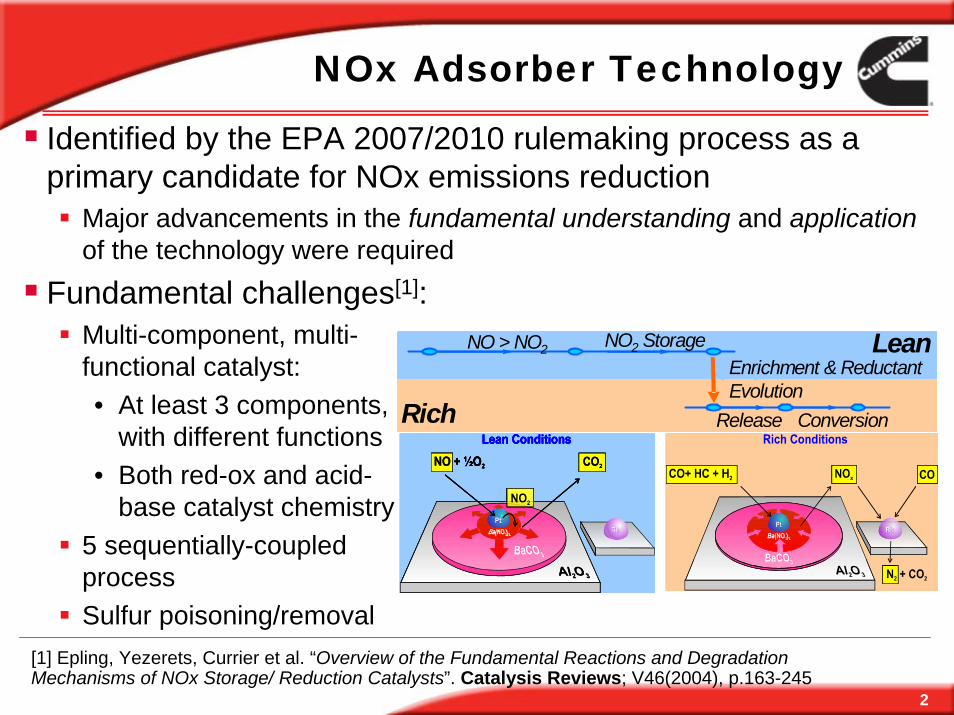
NOx Adsorber Technology

Identified by the EPA 2007/2010 rulemaking process as a primary candidate for NOx emissions reduction

Major advancements in the fundamental understanding and application of the technology were required

Fundamental challenges[1]:

[1] Epling, Yezerets, Currier et al. “Overview of the Fundamental Reactions and Degradation Mechanisms of NOx Storage/ Reduction Catalysts”. Catalysis Reviews; V46(2004), p.163-245

Lean

Rich

NO > NO2 NO2 Storage Enrichment & ReductantEvolution

Lean

Rich Release Conversion

Lean

Rich

NO > NO2 NO2 Storage Enrichment & ReductantEvolution

Lean

Rich Release Conversion

Lean

Rich

NO > NO2 NO2 Storage Enrichment & ReductantEvolution

Lean

Rich Release Conversion

Multi-component, multi-functional catalyst: • At least 3 components,

with different functions• Both red-ox and acid-

base catalyst chemistry5 sequentially-coupled processSulfur poisoning/removal

3

LEV II-ULEV Certified Systemwith Cummins 6.7L Engine and A/T System

Close-Coupled Catalyst (2.1L)• Elliptical metallic substrate,

300 cpsi, by Emitec

NOx Adsorber Catalyst (5.2L)• Cordierite, 300cpsi by Corning

Catalyzed Diesel Particulate Filter (9.4L)• Cordierite, 200 cpsi by NGK

In-cylinder source of reductants and heat for A/T system control, enabled by:

Bosch 1800-bar Common Rail fuel system Cummins next-generation cooled EGRVariable Geometry Turbocharger

4

Several Major Application Challenges

How to make NAC survive deSOx-related aging?

Trade-off between deSOx efficiency and thermal degradation

Different forms of sulfur

Reductant quality

Distribution of temperature and species across the catalyst

How to achieve maximum deNOx performance for a catalyst of a given age?

Catalyst diagnostics

Laboratory and on-board

5

Tradeoff Between deSOxEfficiency and Thermal Deactivation

0

2 0 0

4 0 0

6 0 0

8 0 0

1 0 0 0

1 2 0 0

1 4 0 0

0 .0 1 .0 2 .0 3 .0 4 .0 5 .0tim e , m in

ppm

0

1 0

2 0

3 0

4 0

5 0

6 0

7 0

8 0

9 0

1 0 0

S re

mov

ed, %

S O 2 , p p m

H 2 S , p p m

C O S , p p m

S re m o ve d , % to ta l

0 5 /0 7 /0 4 - 6 0 0 C

0

2 0 0

4 0 0

6 0 0

8 0 0

1 0 0 0

1 2 0 0

1 4 0 0

0 .0 1 .0 2 .0 3 .0 4 .0 5 .0t im e , m in

ppm

0

1 0

2 0

3 0

4 0

5 0

6 0

7 0

8 0

9 0

1 0 0

S re

mov

ed, %

S O 2 , p p m

H 2 S , p p m

C O S , p p m

S re m o v e d , % to ta l

0 4 /2 3 /0 4 - 7 5 0 C , H 2

0 2 4 6 8 1 0 1 2 1 4 1 60

5 0

1 0 0

1 5 0

2 0 0

2 5 0

3 0 0

3 5 0 7 0 0 oC

8 0 0 oC

9 0 0 oC

Pt c

ryst

allin

e si

ze (A

ngst

rom

)

T re a tin g t im e (h r )C a lc in a t io n T im e (h r)

Pt c

ryst

allit

e si

ze (A

ngst

rom

)

0 2 4 6 8 1 0 1 2 1 4 1 60

5 0

1 0 0

1 5 0

2 0 0

2 5 0

3 0 0

3 5 0 7 0 0 oC

8 0 0 oC

9 0 0 oC

Pt c

ryst

allin

e si

ze (A

ngst

rom

)

T re a tin g t im e (h r )C a lc in a t io n T im e (h r)

Pt c

ryst

allit

e si

ze (A

ngst

rom

)

600°C

750°C

deSOx T, °C

NO

x C

apac

ity

NOx Capacity Recovery after DeSOx

Sulfu

r rem

oval Therm

al

deactivation

0 2 4 6 8 1 0 1 20

2 0

4 0

6 0

8 0

1 0 0

7 0 0 o C

8 0 0 o C

9 0 0 o C4 m in 3 0 m in

NO

x up

take

(%)

O 2 t r e a t in g t im e ( h r )

700°C

800°C900°C

Unpublished Cummins dataD.H.Kim et.al. Ind.Eng.Chem.Res.2006,45, 8815

Comprehensive kinetic deSOxmodel developed by Cummins

DeSOx-related degradation understanding from PNNL/ Cummins/ JM CRADA

6

S can exist on NOx adsorbercatalyst in different forms

Chemically uniform (sulfate)Morphologically different (surface/bulk)

Different Forms of Sulfur

020406080

100120140160180

400 600 800 1000T,C

ppm

020406080

100120140160180

400 600 800 1000T,C

ppm

LEAN/RICH

50/10 sec20 cycles

10min

Bypa

ss

5min

Performance test(same as previously)

LEAN

>920°CTPR

RICH4.25%H2, 5%H2O,

5%CO2, balance He

Complete removal of [S]

10°C/min

LEAN/RICH

50/10 sec20 cycles

10min

Bypa

ss

5min

Performance test(same as previously)

LEAN

>920°CTPR

RICH4.25%H2, 5%H2O,

5%CO2, balance He

Complete removal of [S]

10°C/min

[S] form depends on the formation conditions

Can be affected by subsequent re-distribution

Different forms of [S] have different impact on NOx performance

Examples of different forms of S

7

0

30

60

90

120

150

1250 1350 1450 1550 1650 1750time, sec

ppm

Freshly degreened (different test)After SulfationAfter the 300 and 350C points

Original performance

After SO2Poisoning

After ~1h NOxcycling

Sulfated a “Degreened” LNT, Lost ~1/3 of NOx capacityApparent re-distribution of sulfur after ~1 hour normal NOx operation in the 300-400°C range

No sulfur loss confirmed by subsequent temperature-programmed reduction

Example: NOx Adsorber “Memory”

ppm

NO

x

8

Important to distinguish between forms of sulfur

No reason to attempt removing “bulk” sulfur –• Additional thermal

exposure

• Minimal advantage for the “dynamic” NOX capacity

Inherently non-homogeneous species distribution in an integral device

Different Forms of Sulfur/ Distribution Across catalyst

0-1" 1-2" 2-3" 3-4" 4-5"Distance from the inlet face

gS/L

Surface, g/L

Bulk, g/L

Micro-core analysis: minimally invasive (<1cm3 sample) NOx performance, [S] amount and formmultiple locations in the catalyst

9

Gradients in integral devicesGas speciesTemperature Surface species

Pioneering role of NTRC(FEERC)/Cummins CRADA

Importance of Spatially-Resolved Measurements

6 0 &8

- 5

1 5

3 5

5 5

7 5

9 5

0 1 0 2 0 3 0 4 0 5 0 6 0 7 0

T im e

Tem

p o s 1p o s 2p o s 3p o s 4p o s 5p o s 8p o s 1 1p o s 1 4p o s 2 0

-5

15

35

55

75

95

Time, sec

ΔT,

°C

Rich

10 20 30 40 50 60

Pos 1 Pos 20

Sample for IR-thermography

6 0 &8

- 5

1 5

3 5

5 5

7 5

9 5

0 1 0 2 0 3 0 4 0 5 0 6 0 7 0

T im e

Tem

p o s 1p o s 2p o s 3p o s 4p o s 5p o s 8p o s 1 1p o s 1 4p o s 2 0

-5

15

35

55

75

95

Time, sec

ΔT,

°C

Rich

10 20 30 40 50 60

Pos 1 Pos 20

Sample for IR-thermography

Rich: 2% O2, 4%CO, 5%CO2, 5% H2O, N2, Tin=300°CSPACI-MSP-Thermography

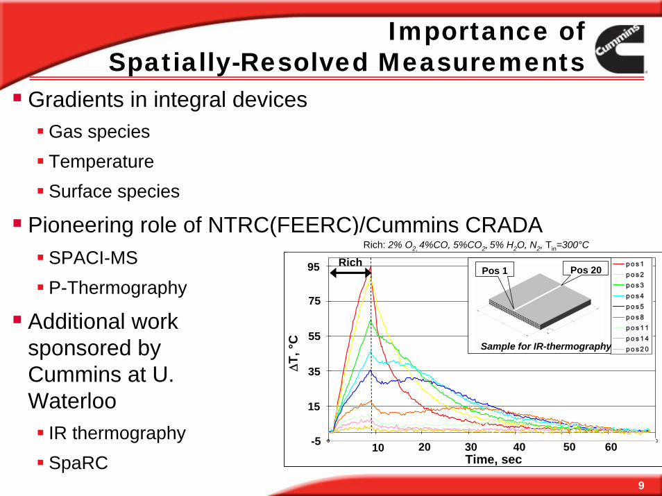
Additional work sponsored by Cummins at U. Waterloo

IR thermographySpaRC

10

0

0.005

0.01

0.015

0.02

0.025

0.03

0 10000 20000 30000 40000 50000

Total Reductant (H2 equivalent), ppm

Nor

mal

ized

deS

Ox

rate

H2 CO

C3H6 C3H8

Reductant Quality

0

50

100

150

200

250

300

350

400

0.0 1.0 2.0 3.0 4.0 5.0time, min

ppm SO2, ppm

COS, ppmH2S, ppm

0

50

100

150

200

250

300

350

400

0.0 1.0 2.0 3.0 4.0 5.0time, min

ppm

SO2, ppmCOS, ppmH2S, ppm

0

200

400

600

800

1000

1200

1400

0.0 1.0 2.0 3.0 4.0 5.0time, min

ppm

SO2, ppmCOS, ppmH2S, ppm

H2

C3H6

C3H8

• CO and H2• C3H6 (model highly reactive HC) • C3H8 (model poorly reactive HC)

Use of efficient reductantsallows to minimize time at deSOx conditions

11

Reductant Quality

In-situ H2 generation may play a major role in deSOx (and deNOx) efficiency

Complex spatial profileBalance in-cylinder and in-situ H2 generation options

J.Parks, M.Swartz, S.Huff, B.West. FEERC/ORNL. DEER 2006, August 20-24, 2006, Detroit, MI

12

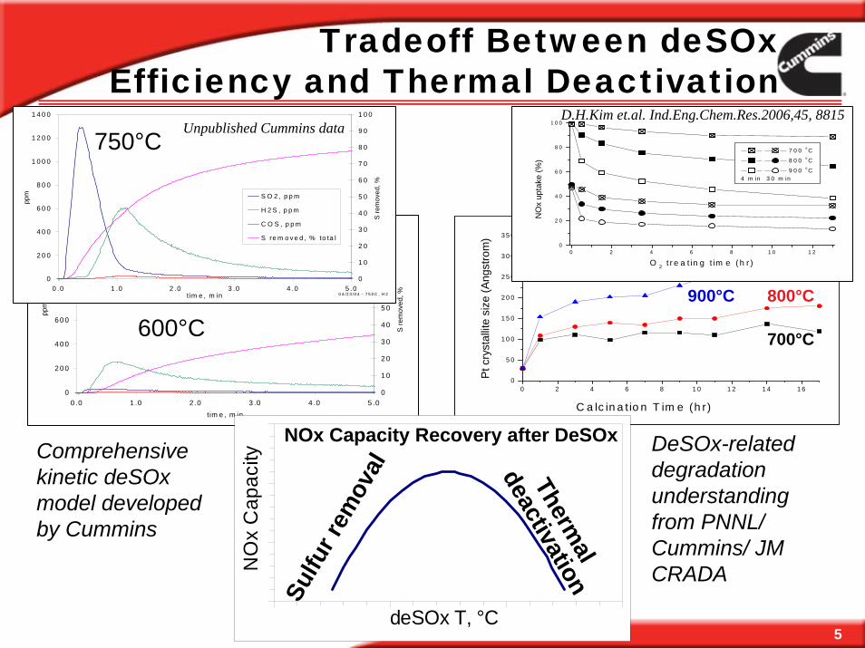
Summary: Balancing Sulfur Removal vs. Thermal Deactivation

Minimize excessive temperature exposure Accurate control of deSOx temperatureMinimize temperature gradients across the NACOptimize reductant qualityTarget only relevant forms of sulfur Capable laboratory diagnostic tools

Loading of removable sulfur

NO

xC

apac

ity Thermal

agingdeSOx

13

SummaryUnderstanding the complexity of the system components (catalysts, sensors) during the design stage allows to develop robust, apparently simple solutions:

In the final product, complexity is reflected in the controls and diagnostics

Significant opportunities remain for further system optimization, e.g.:

Better understanding of the fundamentals of the components behavior (catalysts, sensors), including development of predictive models, would allow for tighter integration Laboratory and on-board diagnostics

14

Acknowledgements

PNNL: Chuck Peden, Do Heui Kim, George Muntean, Tom Gallant, et al.

FEERC (ORNL) Bill Partridge, Jae-Soon Choi, Jim Parks et al.

HTML (ORNL): Tom Watkins, Larry Allard, Ray Johnson et al.

US DOE: Office of Freedom Car and Vehicle Technologies: Partial support through PNGV / Freedom Car program


Recommended