Development of piezoelectric microcantilever flow sensor with wind-driven energy harvesting capability Huicong Liu, Songsong Zhang, Ramprakash Kathiresan, Takeshi Kobayashi, and Chengkuo Lee Citation: Appl. Phys. Lett. 100, 223905 (2012); doi: 10.1063/1.4723846 View online: http://dx.doi.org/10.1063/1.4723846 View Table of Contents: http://apl.aip.org/resource/1/APPLAB/v100/i22 Published by the American Institute of Physics. Related Articles Design of a continuous-flow reactor for in situ x-ray absorption spectroscopy of solids in supercritical fluids Rev. Sci. Instrum. 83, 054101 (2012) Fiber-optic liquid level sensor based on coupling optical path length variation Rev. Sci. Instrum. 83, 055006 (2012) A universal noncontact flowmeter for liquids Appl. Phys. Lett. 100, 194103 (2012) Accelerated drop detachment in granular suspensions Phys. Fluids 24, 043304 (2012) Turbulence measurements in a rotating magnetic field driven flow Phys. Fluids 24, 045105 (2012) Additional information on Appl. Phys. Lett. Journal Homepage: http://apl.aip.org/ Journal Information: http://apl.aip.org/about/about_the_journal Top downloads: http://apl.aip.org/features/most_downloaded Information for Authors: http://apl.aip.org/authors
Transcript
Development of piezoelectric microcantilever flow sensor with wind-drivenenergy harvesting capabilityHuicong Liu, Songsong Zhang, Ramprakash Kathiresan, Takeshi Kobayashi, and Chengkuo Lee Citation: Appl. Phys. Lett. 100, 223905 (2012); doi: 10.1063/1.4723846 View online: http://dx.doi.org/10.1063/1.4723846 View Table of Contents: http://apl.aip.org/resource/1/APPLAB/v100/i22 Published by the American Institute of Physics. Related ArticlesDesign of a continuous-flow reactor for in situ x-ray absorption spectroscopy of solids in supercritical fluids Rev. Sci. Instrum. 83, 054101 (2012) Fiber-optic liquid level sensor based on coupling optical path length variation Rev. Sci. Instrum. 83, 055006 (2012) A universal noncontact flowmeter for liquids Appl. Phys. Lett. 100, 194103 (2012) Accelerated drop detachment in granular suspensions Phys. Fluids 24, 043304 (2012) Turbulence measurements in a rotating magnetic field driven flow Phys. Fluids 24, 045105 (2012) Additional information on Appl. Phys. Lett.Journal Homepage: http://apl.aip.org/ Journal Information: http://apl.aip.org/about/about_the_journal Top downloads: http://apl.aip.org/features/most_downloaded Information for Authors: http://apl.aip.org/authors
1Department of Electrical and Computer Engineering, National University of Singapore,9 Engineering Drive 1, Singapore 1175762National Institute of Advanced Industrial Science and Technology (AIST), 1-2-1 Namiki, Tsukuba, Ibaraki305-8564, Japan
(Received 22 March 2012; accepted 7 May 2012; published online 31 May 2012)
We have developed a piezoelectric (PZT) microcantilever as an air flow sensor and a wind-driven
energy harvester for a self-sustained flow-sensing microsystem. A flow sensing sensitivity of 0.9 mV/
(m/s) is obtained. The output voltage and optimized power regarding to the load resistance of 100 kXare measured as 18.1 mV and 3.3 nW at flow velocity of 15.6 m/s, respectively. The corresponding
power density is as large as 0.36 mW/cm3. The experimental results have elucidated the smart
function of using PZT microcantilevers as flow-sensors and wind-driven energy harvesters
simultaneously. VC 2012 American Institute of Physics. [http://dx.doi.org/10.1063/1.4723846]
At present, the development of ultra low-power micro-
electronics and circuits has opened a promising research
direction to self-sustained wireless microsensor nodes with-
out using battery.1 An interesting preliminary concept has
been demonstrated such as a self-powered system using a
nano-power-generator for long distance wireless data trans-
mission.2 Aiming at a self-sustained flow-sensing microsys-
tem as a wireless sensor node for future applications
including smart home, factory automation, and environmental
monitoring in rural field or agricultural land, it requires not
only the micro-scale flow sensors and control circuits with
the capabilities of sensing, monitoring, and communicating
but also a renewable micro-scale power source by scaveng-
ing energy from environment.
Piezoelectric materials are widely adopted in microsen-
sors for characterization of regimes including pressure, accel-
eration, strain, or force by converting them into electrical
charge based on piezoelectric effect.3 In particular, Seo and
Kim4 have reported a piezoelectric micro flow sensor by
measuring the resonant frequency changes with respect to
different flow velocities. We have proposed a flow-sensing
approach by measuring the output voltage of the piezoelectric
microcantilever from air flow-induced vibrations. Comparing
with conventional micro flow sensors, piezoelectric-based
micro flow sensors do not require additional power to mea-
sure mechanical strain,5 Coriolis force,6 or thermal flux7 and
have not been reported until our study. On the other hand,
wind energy regarded as a renewable energy source is present
everywhere in open environments. So far, a few large scale
wind-driven energy harvesters8,9 have been reported but are
less developed at micro-scales. We thus aim to investigate
MEMS energy harvesting from wind flow using a flexible
piezoelectric microcantilever. The significance of this con-
cept is that it does not require an external vibration source
eliminating the bandwidth issue of traditional vibration-
driven energy harvesters10–13 and combines aerodynamics
with vibrations to generate necessary power.
Since piezoelectric microcantilever is a promising can-
didate for a self-sustained flow-sensing microsystem due to
its passive nature, i.e., detectable output charge is a function
of flow rate, we have characterized the flow sensing and
energy harvesting capabilities of a wind-driven piezoelectric
(PZT) microcantilever. More specifically, a self-sustained
flow-sensing microsystem with an array of similar PZT
microcantilevers will be able to measure the flow rate of am-
bient wind by one microcantilever while the rest are used to
scavenge wind energy.
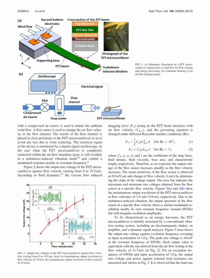
Figure 1(a) shows a schematic illustration of a PZT
microcantilever immersed in a wind flow along a parallel
incidence direction (x-direction) with respect to the cantile-
ver surface. The PZT microcantilever consists of a 3000-lm-
long and 300-lm-wide PZT beam sandwiched by top and
bottom electrodes and a 5-lm-thick Si supporting layer, as
seen from the cross section view. The microfabrication pro-
cess is started from a SOI wafer with 5 lm Si device layer,
1 lm buried oxide layer, and 400 lm Si handle layer. A ther-
mal oxide layer of 0.3 lm is initially deposited on the Si de-
vice layer before bottom electrode of LaNiO3 (0.2 lm)/
Pt(0.2 lm)/Ti(0.05 lm) is deposited by RF (for LaNiO3) and
dc magnetron sputtering (for Pt/Ti). A 3-lm-thick PZT thin
film is then deposited by sol-gel technique. This (100) crys-
tallographic orientation helps in maximizing the dielectric
constant and electrical properties of the PZT film. The depos-
ited films are then pyrolyzed and crystallized by rapid ther-
mal annealing. Finally, Pt/LaNiO3 layers are sputtered on top
of the PZT film to form a top electrode. The photograph of
the final released PZT microcantilever is shown in the same
figure. A bent cantilever design is utilized for achieving the
maximum amount of momentum from the wind flow and
hence obtaining maximum transduction from wind energy to
mechanical vibration and eventually electrical energy.
The flow sensing capability of the PZT microcantilever
is characterized by using an air flow testing system as shown
in Fig. 1(b). A flow channel of diameter 3.5 mm connected
a)Author to whom correspondence should be addressed. Electronic mail:
with a compressed air source is used to mimic the ambient
wind flow. A flow meter is used to change the air flow veloc-
ity in the flow channel. The nozzle of the flow channel is
placed at close proximity to the PZT microcantilever so as to
avoid any loss due to wind scattering. The electrical signal
of the device is monitored by a digital signal oscilloscope. In
the case when the PZT microcantilever is completely
immersed within the air flow boundary layer, it will oscillate
in a turbulence-induced vibration mode14 and exhibit a
modulated response nearby its resonant frequency.4
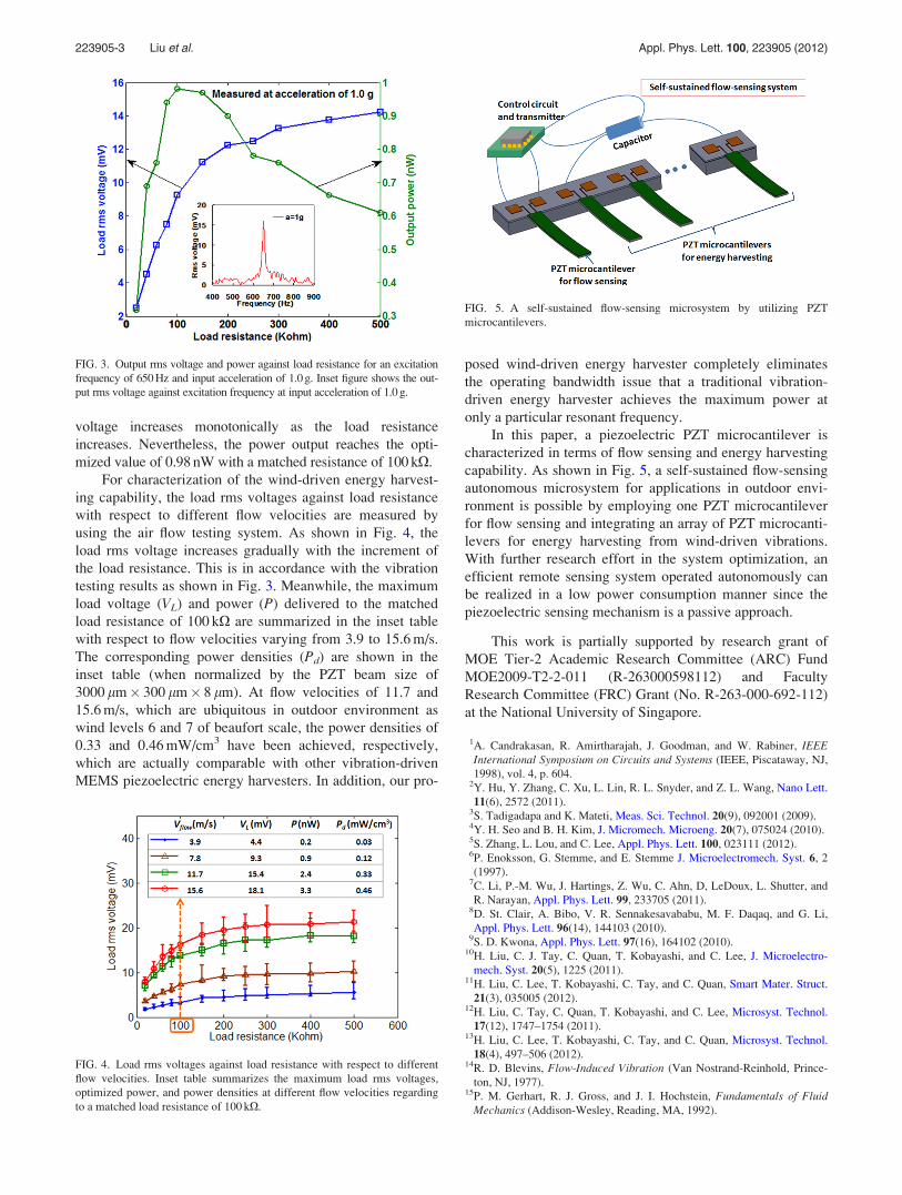
Figure 2 shows the output rms voltage of the PZT micro-
cantilever against flow velocity varying from 0 to 19.5 m/s.
According to fluid dynamics,15 the viscous flow induced
dragging force (Fd) acting on the PZT beam increases with
air flow velocity (Vflow), and the governing equation is
changed under different Reynolds number conditions (Re).
Fd ¼1
2CdqV2
flowA ðfor Re > 103Þ; (1)
Fd ¼ CdlVflowl ðfor Re < 1Þ; (2)
where Cd, q, l, A, and l are the coefficient of the drag force,
fluid density, fluid viscosity, base area, and characteristic
length, respectively. Therefore, as we expected, the output volt-
age of the flow sensor increases steadily as the flow velocity
increases. The mean sensitivity of the flow sensor is observed
as 0.9 mV per unit change of flow velocity (1 m/s) by determin-
ing the slope of the voltage output. The error bar indicates the
maximum and minimum rms voltages obtained from the flow
sensor at a specific flow velocity. Figures 2(a) and 2(b) show
the instantaneous output waveforms of the PZT microcantilever
at flow velocities of 3.9 and 15.6 m/s, respectively. Due to the
turbulence-induced vibration, the output spectrum of the flow
sensor at a specific flow velocity shows a similar modulated os-
cillation nearby its own resonant frequency (around 650 Hz)
but with irregular oscillation amplitudes.
To be characterized as an energy harvester, the PZT
microcantilever is initially measured by a conventional vibra-
tion testing system, including an electromagnetic shaker, an
amplifier, and a dynamic signal analyzer. Figure 3 inset shows
the output rms voltage against excitation frequency sweeping
at input acceleration of 1.0 g. The peak rms voltage is 16 mV
at the resonant frequency of 650 Hz. Such output value is
equivalent with the one derived from the air flow testing at the
flow velocity of 11.7 m/s (in Fig. 2). For an excitation fre-
quency of 650 Hz and input acceleration of 1.0 g, the output
rms voltage and power against external load resistance are
measured and shown in Fig. 3. It is observed that the load rms
FIG. 1. (a) Schematic illustration of a PZT micro-
cantilever immersed in a wind flow for flow sensing
and energy harvesting; (b) schematic drawing of an
air flow testing system.
FIG. 2. Output rms voltages of the PZT microcantilever against flow veloc-
ities varying from 0 to 19.5 m/s. Inset (a) instantaneous output waveform at
flow velocity of 3.9 m/s; (b) instantaneous output waveform at flow velocity
of 15.6 m/s.
223905-2 Liu et al. Appl. Phys. Lett. 100, 223905 (2012)
voltage increases monotonically as the load resistance
increases. Nevertheless, the power output reaches the opti-
mized value of 0.98 nW with a matched resistance of 100 kX.
For characterization of the wind-driven energy harvest-
ing capability, the load rms voltages against load resistance
with respect to different flow velocities are measured by
using the air flow testing system. As shown in Fig. 4, the
load rms voltage increases gradually with the increment of
the load resistance. This is in accordance with the vibration
testing results as shown in Fig. 3. Meanwhile, the maximum
load voltage (VL) and power (P) delivered to the matched
load resistance of 100 kX are summarized in the inset table
with respect to flow velocities varying from 3.9 to 15.6 m/s.
The corresponding power densities (Pd) are shown in the
inset table (when normalized by the PZT beam size of
3000 lm� 300 lm� 8 lm). At flow velocities of 11.7 and
15.6 m/s, which are ubiquitous in outdoor environment as
wind levels 6 and 7 of beaufort scale, the power densities of
0.33 and 0.46 mW/cm3 have been achieved, respectively,
which are actually comparable with other vibration-driven
MEMS piezoelectric energy harvesters. In addition, our pro-
posed wind-driven energy harvester completely eliminates
the operating bandwidth issue that a traditional vibration-
driven energy harvester achieves the maximum power at
only a particular resonant frequency.
In this paper, a piezoelectric PZT microcantilever is
characterized in terms of flow sensing and energy harvesting
capability. As shown in Fig. 5, a self-sustained flow-sensing
autonomous microsystem for applications in outdoor envi-
ronment is possible by employing one PZT microcantilever
for flow sensing and integrating an array of PZT microcanti-
levers for energy harvesting from wind-driven vibrations.
With further research effort in the system optimization, an
efficient remote sensing system operated autonomously can
be realized in a low power consumption manner since the
piezoelectric sensing mechanism is a passive approach.
This work is partially supported by research grant of
MOE Tier-2 Academic Research Committee (ARC) Fund
MOE2009-T2-2-011 (R-263000598112) and Faculty
Research Committee (FRC) Grant (No. R-263-000-692-112)
at the National University of Singapore.
1A. Candrakasan, R. Amirtharajah, J. Goodman, and W. Rabiner, IEEEInternational Symposium on Circuits and Systems (IEEE, Piscataway, NJ,
1998), vol. 4, p. 604.2Y. Hu, Y. Zhang, C. Xu, L. Lin, R. L. Snyder, and Z. L. Wang, Nano Lett.
11(6), 2572 (2011).3S. Tadigadapa and K. Mateti, Meas. Sci. Technol. 20(9), 092001 (2009).4Y. H. Seo and B. H. Kim, J. Micromech. Microeng. 20(7), 075024 (2010).5S. Zhang, L. Lou, and C. Lee, Appl. Phys. Lett. 100, 023111 (2012).6P. Enoksson, G. Stemme, and E. Stemme J. Microelectromech. Syst. 6, 2
(1997).7C. Li, P.-M. Wu, J. Hartings, Z. Wu, C. Ahn, D, LeDoux, L. Shutter, and
R. Narayan, Appl. Phys. Lett. 99, 233705 (2011).8D. St. Clair, A. Bibo, V. R. Sennakesavababu, M. F. Daqaq, and G. Li,
Appl. Phys. Lett. 96(14), 144103 (2010).9S. D. Kwona, Appl. Phys. Lett. 97(16), 164102 (2010).
10H. Liu, C. J. Tay, C. Quan, T. Kobayashi, and C. Lee, J. Microelectro-
mech. Syst. 20(5), 1225 (2011).11H. Liu, C. Lee, T. Kobayashi, C. Tay, and C. Quan, Smart Mater. Struct.
21(3), 035005 (2012).12H. Liu, C. Tay, C. Quan, T. Kobayashi, and C. Lee, Microsyst. Technol.
17(12), 1747–1754 (2011).13H. Liu, C. Lee, T. Kobayashi, C. Tay, and C. Quan, Microsyst. Technol.
18(4), 497–506 (2012).14R. D. Blevins, Flow-Induced Vibration (Van Nostrand-Reinhold, Prince-
ton, NJ, 1977).15P. M. Gerhart, R. J. Gross, and J. I. Hochstein, Fundamentals of Fluid
Mechanics (Addison-Wesley, Reading, MA, 1992).
FIG. 4. Load rms voltages against load resistance with respect to different
flow velocities. Inset table summarizes the maximum load rms voltages,
optimized power, and power densities at different flow velocities regarding
to a matched load resistance of 100 kX.
FIG. 5. A self-sustained flow-sensing microsystem by utilizing PZT
microcantilevers.
FIG. 3. Output rms voltage and power against load resistance for an excitation
frequency of 650 Hz and input acceleration of 1.0 g. Inset figure shows the out-
put rms voltage against excitation frequency at input acceleration of 1.0 g.
223905-3 Liu et al. Appl. Phys. Lett. 100, 223905 (2012)