127
ORNL/TM-2001/222 DEVELOPMENT OF PROOF-OF- CONCEPT UNITS FOR THE ADVANCED MEDIUM-SIZED MOBILE POWER SOURCES (AMMPS) PROGRAM March 2002

ORNL/TM-2001/222
DEVELOPMENT OF PROOF-OF-CONCEPT UNITS FOR THE ADVANCED MEDIUM-SIZED MOBILE POWER SOURCES (AMMPS) PROGRAM
March 2002

DOCUMENT AVAILABILITY Reports produced after January 1, 1996, are generally available free via the U.S. Department of Energy (DOE) Information Bridge: Web site: http://www.osti.gov/bridge Reports produced before January 1, 1996, may be purchased by members of the public from the following source: National Technical Information Service 5285 Port Royal Road Springfield, VA 22161 Telephone: 703-605-6000 (1-800-553-6847) TDD: 703-487-4639 Fax: 703-605-6900 E-mail: [email protected] Web site: http://www.ntis.gov/support/ordernowabout.htm Reports are available to DOE employees, DOE contractors, Energy Technology Data Exchange (ETDE) representatives, and International Nuclear Information System (INIS) representatives from the following source: Office of Scientific and Technical Information P.O. Box 62 Oak Ridge, TN 37831 Telephone: 865-576-8401 Fax: 865-576-5728 E-mail: [email protected] Web site: http://www.osti.gov/contact.html
This report was prepared as an account of work sponsored by an agency of the United States government. Neither the United States government nor any agency thereof, nor any of their employees, makes any warranty, express or implied, or assumes any legal liability or responsibility for the accuracy, completeness, or usefulness of any information, apparatus, product, or process disclosed, or represents that its use would not infringe privately owned rights. Reference herein to any specific commercial product, process, or service by trade name, trademark, manufacturer, or otherwise, does not necessarily constitute or imply its endorsement, recommendation, or favoring by the United States government or any agency thereof. The views and opinions of authors expressed herein do not necessarily state or reflect those of the United States government or any agency thereof.

ORNL/TM-2001/222
Engineering Science and Technology Division
DEVELOPMENT OF PROOF-OF-CONCEPT UNITS FOR THE ADVANCED MEDIUM-SIZED MOBILE POWER SOURCES (AMMPS) PROGRAM
Compiled by
J. B. Andriulli
M. B. Scudiere C. P. White
G. Farquaharson T. J. Theiss C. W. Ayers
C. L. Coomer David Eddy, E&M Power
H. D. Ferguson, UTK E. J. Hardin, BWXT Y-12
H. D. Haynes M. S. Hileman
D. K. Irick, UTK L. B. Klett
P. J. Otaduy G. W. Ott
William Peterson, E&M Power L. E. Sieber
J. F. Thomas L. M. Tolbert, UTK
Manuscript completed: March 2002
Date published: March 2002
Prepared by Oak Ridge National Laboratory
Oak Ridge, TN 37831 Managed by UT-Battelle, LLC
For the U. S. Department of Energy
Under contract DE-AC05-00OR22725

CONTENTS
Page FIGURES ........................................................................................................................................vii TABLES .......................................................................................................................................... ix EXECUTIVE SUMMARY................................................................................................................. xi ABSTRACT ..................................................................................................................................... 1 1. INTRODUCTION.................................................................................................................... 1 1.1 BACKGROUND............................................................................................................. 2 1.2 APPROACH................................................................................................................... 2 1.3 SYSTEM DESIGN FLOW.............................................................................................. 3 1.4 PURPOSE OF REPORT ............................................................................................... 4 2. UPDATED RECOMMENDATIONS FOR A DESIGN PHILOSOPHY ..................................... 7 3. DESIGN AND ANALYSIS OF MECHANICAL SYSTEMS......................................................13 3.1 ENGINE DESIGN ..........................................................................................................13 3.1.1 Engine Selection................................................................................................13 3.1.2 Engine Characterization- Ruggerini engine .......................................................14 3.1.3 High Temperature Testing .................................................................................14 3.1.4 Wetstacking Analysis .........................................................................................15 3.1.5 Analysis of Ruggerini Engine.............................................................................16 3.1.6 Lessons Learned from Engine Characterization................................................16 3.2 PERMANENT MAGNET (PM) ALTERNATOR..............................................................17 3.2.1 Variable Speed Alternator Design......................................................................18 3.2.2 Alternator / Engine Performance Match Design Approach ................................18 3.2.3 Alternator Performance and Analysis ................................................................19 3.2.4 Alternator Lessons Learned...............................................................................20 4. ELECTRICAL SYSTEMS DESIGN AND ANALYSIS .............................................................33 4.1 POWER ELECTRONICS DESIGN................................................................................33 4.1.1 Asynchronous Boost Design..............................................................................34 4.1.2 Inverter and Output Filter Design.......................................................................35 4.1.3 Bi-Directional Converter Design.........................................................................35 4.1.4 Analysis of Power Electronics System...............................................................36 4.2 DIGITAL CONTROL SYSTEM (INCLUDING DIAGNOSTICS & PROGNOSTICS)......36 4.2.1 Digital v. analog control......................................................................................36 4.2.2 Hardware Requirements ....................................................................................37 4.2.3 User Interface ....................................................................................................38 4.2.4 DSP selection ....................................................................................................38 4.2.5 Gen-Set Instrumentation....................................................................................39 4.2.6 Control Flow.......................................................................................................40 4.2.7 Additional Features............................................................................................42 4.2.8 Diagnostics & Prognostics .................................................................................42 4.3 ANALYSIS OF POWER ELECTRONICS AND DIGITAL CONTROL SYSTEMS..........42 4.3.1 DC Link Voltage.................................................................................................43 4.3.2 Electrical Noise and Noise Suppression............................................................43 4.3.3 Alternator Boost Circuit ......................................................................................44 4.3.4 Digital Controls...................................................................................................45 4.3.5 Display ...............................................................................................................45 4.4 LESSONS LEARNED FROM POWER ELECTRONICS AND DIGITAL CONTROLS....................................................................................................45
iii

5. SYSTEMS INTEGRATION.....................................................................................................57 5.1 FRAME & ENCLOSURE DESIGN.................................................................................57 5.1.1 Enclosure Material .............................................................................................57 5.1.2 Skid-Based Housing Design ..............................................................................57 5.1.3 Skid / Housing Lessons Learned .......................................................................58 5.2 ACOUSTICS..................................................................................................................58 5.2.1 Acoustic Lessons Learned.................................................................................60 5.3 VIBRATION ISOLATION AND SHOCK.........................................................................60 5.3.1 Isolator Background...........................................................................................60 5.3.2 Isolator Tests .....................................................................................................61 5.3.3. Small Gen-set Data............................................................................................62 5.3.4 Large Gen-set Data ...........................................................................................63 5.3.5 Isolator Mount Lessons Learned........................................................................63 5.4. AIR FLOW AND HEAT ..................................................................................................64 5.4.1 Air-cooled vs. water-cooled engines ..................................................................64 5.4.2 Air Flow and Temperature Data.........................................................................65 5.4.3 Large Gen-set Design Configuration .................................................................66 5.4.4 Lessons Learned, heat rejection........................................................................66 5.5 ANALYSIS OF FRAME AND ENCLOSURE..................................................................67 6. PERFORMANCE CHARACTERISTICS.................................................................................81 6.1 ELECTRICAL OUTPUTS ..............................................................................................81 6.2 SYSTEM RATING .........................................................................................................81 6.3 POWER QUALITY.........................................................................................................82 6.3.1 Waveform...........................................................................................................82 6.3.2 Total Harmonic Distortion (THD)........................................................................82 6.3.3 Voltage Stability .................................................................................................83 6.3.4 Frequency Stability ............................................................................................83 6.4 TRANSIENT LOAD OPERATION .................................................................................84 6.5 OPTIMUM VARIABLE SPEED OPERATION................................................................84 6.6 MEASURED SYSTEM EFFICIENCY ............................................................................85 6.6.1 Lessons Learned on System Optimization ........................................................86 6.7 VARIABLE SPEED CONTROL .....................................................................................87 6.8 WEIGHT AND VOLUME................................................................................................88 6.9 SYSTEM LESSONS LEARNED ....................................................................................90 7. SUMMARY OF LESSONS LEARNED AND FUTURE SPECIFICATIONS ............................99 7.1 SUMMARY OF LESSONS LEARNED ..........................................................................99 7.1.1 Engine Lessons Learned (Section 3.1.6) .............................................................99 7.1.2 Alternator Lessons Learned (Section 3.2.4) .........................................................99 7.1.3 Lessons Learned from Power Electronics and Digital Controls (Section 4.4) ...........................................................................................99 7.1.4 Systems Integration Lessons Learned (Sections 5.1.3, 5.2.1, 5.3.5, and 5.4.4)................................................................102 7.1.5 Lessons Learned on System Optimization ...........................................................103 7.2 RECOMMENDATIONS FOR FUTURE SPECIFICATIONS ..........................................104 7.2.1 Family Sizes & Modes .......................................................................................104 7.2.2 Gen-set Weight and Volume..............................................................................104 7.2.3 Fuel Consumption..............................................................................................105 7.2.4 Acoustics ...........................................................................................................106 7.2.5 Power Quality.....................................................................................................106 7.2.6 Low Power Factor Loads ...................................................................................106 7.2.7 Unbalanced Loads.............................................................................................107
iv

7.2.8 Parallel Operation ..............................................................................................107 7.2.9 Gen-set System Protection ................................................................................107
7.3 CLOSURE .....................................................................................................................107 8. REFERENCES.......................................................................................................................111
v


FIGURES Figure Page 3.1 Chart of engine weight vs. estimated power range for the lightweight engines (small and
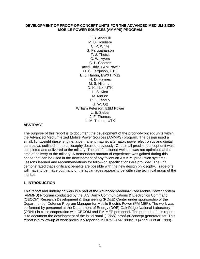
medium sized gen-sets) ...................................................................................................21 3.2 Peak torque, power, and fuel consumption for the Ruggerini MD191 diesel engine in proof
of concept gen-set. ..............................................................................................................22 3.3 Engine performance map of the Ruggerini MD191 engine used for the small gen-set ..........23 3.4 Ruggerini MD191 engine data at ambient and elevated temperatures and using JP-8 ........24 3.5 Ruggerini MD191 test results of engine power at elevated temperatures .............................25 3.6 Ruggerini MD191 emissions data at 3600 rpm ....................................................................26 3.7 Wetstacking analysis showing the location where wetstacking is most likely to occur ..........27 3.8 Small Ruggerini MD191 engine/alternator design match approach ......................................28 3.9 Large DDC VMM D706LT engine/alternator design match approach ...................................29 3.10 PM alternator mounted to small gen-set Ruggerini MD191 engine .......................................30 3.11 RMS and maximum voltage as a function of speed for the small PM alternator (before rewind).................................................................................................30 3.12 Small PM alternator waveforms (after correcting phase wiring) .............................................31 4.1 Functional block diagram of power conversion components in generator set........................49 4.2 Schematic of gen-set boost rectifier .......................................................................................50 4.3 Schematic of gen-set inverter and filters ................................................................................50 4.4 Pre- and post-filtered line-neutral output voltage waveforms from the proof of concept gen-set.........................................................................................................51 4.5 Filtered line-neutral inverter output voltage waveforms..........................................................51 4.6 Schematic of gen-set bi-directional converter ........................................................................52 4.7 DC link voltage maintained by boost from bi-directional converter upon loss of voltage from prime mover ...................................................................................................................52 4.8 Small gen-set user interface and display panel (top half of picture) and field output
connections and voltage configuration and frequency selection switches (bottom half of picture) ...................................................................................................................................53
4.8 Diagnostic and prognostics monitored parameters ...............................................................54 4.10 Data monitored in the small AMMPS gen-set.........................................................................55 5.1 Small gen-set with control panel and display, computer access, cable connection access
door and convenience plug ....................................................................................................68 5.2 Small gen-set showing fuel tank fill, hot air and engine exhaust vent grill on top with side
double folded access door open ............................................................................................69 5.3 Small gen-set, battery and silencer side, double-hinged access door open, connector
cable opening and NATO plug receptacle, cooling air inlet for power electronics box........................................................................................................70 5.4 Control and display panel access door open, power connectors, silencer and battery side
double-hinged door open .......................................................................................................71 5.5 Small gen-set acoustic measurements at 7 m........................................................................72 5.6 Small gen-set motor mount vibration isolation comparison ....................................................73 5.7 Small gen-set measured airflow versus load.........................................................................74 5.8 Small gen-set control speed versus load................................................................................75 5.9 Small gen-set inlet and outlet temperature rise versus load...................................................76 5.10 Large gen-set skid and housing .............................................................................................77 5.11 Large gen-set skid and housing. Alternator-end and silencer-side of the gen-set ................78 5.12 Large gen-set skid and housing. Radiator-end and silencer-side of the gen-set ..................79 5.13 Large gen-set skid and housing. Radiator-end and throttle-side of the gen-set....................80
vii

6.1 Output waveform for 120V, three phase, 60 Hz output at ~1kW............................................92 6.2 Output waveform for 120V, three phase, 60 Hz output at ~8kW............................................92 6.3 Output waveform for 115V, three phase, 60 Hz output at ~1kW............................................93 6.4 Output waveform for 115V, three phase, 60 Hz output at ~8kW............................................93 6.5 Estimated efficiency map of the small proof-of-concept gen-set system................................94 6.6 Measured system efficiency as a function of load..................................................................95 6.7 Engine speed as a function of output power showing variable speed operation....................96 6.8 Estimated and measured efficiency as a function of load and engine speed.........................97 6.9 Normalized TQG and AMMPS data comparing the efficiency of fixed vs. variable speed
control.....................................................................................................................................98 7.1. Specific weight trend lines for the TQG, prototype, and future production medium sized
gen-sets..................................................................................................................................109 7.2. Specific volume trend lines for the TQG, prototype, and future production medium sized
gen-sets..................................................................................................................................110
viii

TABLES Table Page 6.1 THD measurements for 120V, 60 Hz, three phase output at various loads levels .................83 6.2 THD measurements for 115V, 60 Hz, three phase output at various loads levels .................83 6.3 Fuel saved due to variable-speed control relative to fixed-speed control...............................87 6.4 Estimated weight budget for the small proof-of-concept unit..................................................89
ix


xi
EXECUTIVE SUMMARY This report and underlying work is a part of the Advanced Medium-Sized Mobile Power System (AMMPS) Program conducted by the U.S. Army Communications & Electronics Command (CECOM) Research Development & Engineering (RD&E) Center under sponsorship of the Department of Defense Program Manager for Mobile Electric Power (PM-MEP). The work was performed by personnel at the Department of Energy (DOE) Oak Ridge National Laboratory (ORNL) in close cooperation with CECOM and PM-MEP personnel. The purpose of this report is to document the development of the initial small (~8kW) proof-of-concept generator set. This report is a follow-up of work previously reported in ORNL-TM-1999/213, Advanced Power Generation Systems for the 21st Century: Market Survey & Recommendations for a Design Philosophy. The primary criteria and requirements for the proof-of-concept units were: • 50, 60, & 400 Hz from single unit • Reduce gen-set weight (up to 55%) • Reduce gen-set volume • Increase fuel efficiency • Maximize flexibility • Low acoustic signature (65 dBA at 7 m) • Keep production costs low • Maintain system reliability • Meet aggressive proof-of-concept schedule While much of this information in this document will directly relate to any future designs, significant differences exist between the proof-of-concept units and the production units. The primary differences are the ambitious schedule of the proof-of-concept phase, and the low quantities produced. Components The following is a verbal flow chart of the various components and subsystems used in the AMMPS proof-of-concept generator set. Although these components are specific to the small proof-of-concept size, similar philosophy and design is applicable to larger units. Engine: The engine is the thermodynamic conversion from diesel fuel (DF-2) or JP8 to a rotating shaft from 2000 RPM to 3600 RPM. We use a lightweight two-cylinder, aluminum diesel engine (Ruggerini MD191) operated under variable speed control as the prime mover for the small proof-of-concept gen-set. The variable speed control is a significant departure from typical gen-set designs and is discussed at much length in the report. Alternator: An alternator converts the shaft power of the engine to three-phase electrical output with a center tap or neutral connection that is referenced to ground. In this system the alternator is a permanent magnet (PM) design with a trapezoidal output waveform that is directly coupled to the engine. Direct coupling of the alternator to the engine means that the output frequency will vary with the engine speed. In this unit, power electronics not typically used in gen-sets is necessary to produce the desired output power signal.

xii
Rectifier and alternator boost circuit: This is the first of five different power electronics modules whose function is to convert the three-phase output power from the alternator to a positive and negative DC link voltage of about 400-500 Volts. The voltage of the PM alternator is directly proportional to the engine speed under normal operation. The boost circuit provides a means to raise the voltage the alternator produces to a minimum of 400V nominal. DC Link: The DC link is the “bridge” between the input power and the output power. The DC voltage, “links” the different frequencies of the input to the different frequencies of the output. Inverter: The conversion of DC to a suitable AC signal is done with a power electronics inverter. Our inverter is primarily an arrangement of six power transistors that switch the three output lines between the positive and negative DC link lines in such a way as to produce the desired AC waveforms. Filter: The filter is a passive component composed of capacitors and inductors that filter out the higher frequencies of the inverter and create a smooth output waveform. It is the job of the low pass filter to smooth out the undesirable noise and produce a smooth sinusoidal output. Battery charge and boost circuit: The battery charge and boost circuit provides a means of charging the battery from the DC link voltage as well as reversing the process to provide power to the link from the battery during transient loads. Supplementing the DC link with battery voltage allows the engine to be more responsive to large load changes and provides a more stable output signal. Control: The functioning of all the above is orchestrated by the control system. Its job is to make all the above work together upon direction from an operator in an efficient manner and produce the desired output. The control system not only the controls the electrical power to the load but also supplies information to the operator on the status of the system. In our system, we custom designed a digital control system for maximum flexibility. Frame and Enclosure All of the above components are packaged together on a skid for structural support that is enclosed to reduce the acoustic signature and provide protection. The frame, skid, and enclosure were made from aluminum and the enclosure was completely lined with standard acoustic foam for sound abatement. Performance Results The proof-of-concept unit performed well and demonstrated the technical feasibility of the general design philosophy. Many lessons were learned during the proof-of-concept phase and additional areas needing additional improvements are identified in the main body of the report. All of the problem areas are considered fixable with relatively minor alterations. The unit as delivered was functional but not optimized. Additional improvement in the same unit can be expected. Some areas will require minor design changes to realize the full benefit. A synopsis of the performance is listed here: • Electrical output – the quality of the electrical output varied. All options (3 voltage levels, 3
frequencies) were working at some level. The results for 50 & 60 Hz, 208V,three phase

xiii
output were quite good; 400 Hz operation is marginal. With tuned filters for the two frequencies, the 400 Hz output should be acceptable. Additional filters are needed to allow for unbalanced loads.
• System rating – we estimate the system would be rated at 8 kW which is slightly more than we originally anticipated
• Power quality – the power quality can be quite good but was not consistent at all conditions. The waveform quality needs additional filters and refinement of the controls and electronics. The waveform stability (voltage and frequency) is excellent.
• Transient load Operation – this works quite well. The automated controls can be adjusted to ramp up the engine in 2-3 seconds. The battery boost is an effective means to supplement engine power with battery power during transient loads. Additional refinement of the battery boost would improve transient load operation even further.
• Optimum variable speed operation – the gen-set operates under variable speed control effectively. The gen-set operates at ~2200 rpm at loads of ~4 kW or less and increases to ~3600 rpm at full load. The optimization of the controls scheme requires some iteration to assure ample margin for transient loads.
• System efficiency – the overall maximum system efficiency was measured at ~25% at full load. Multiple benefits of variable speed control were realized (over fixed speed control). Partial load efficiency at 25% and 50% load was ~10% higher for variable speed control over fixed speed. Variable speed control also allowed for the small unit to be rated at 8 kW rather than 4 kW.
• Weight and volume – Significant weight and volume reductions were realized. The unit as delivered weighed ~524 lb (dry) and 549 lb (wet) and was ~29 cu ft in size. A 10 kW TQG weighs ~1200 lb with a volume of 41 cu ft.
Lessons Learned Many lessons were learned during the design and fabrication of the proof-of-concept phase. The detailed listing of the lessons learned is in the main body of the report but some of the key lessons learned are provided here: • The new injection technology available today can provide significant benefits that warrant
full military consideration. • Matching the engine and alternator power curves is a good first-cut design approach. • The interface between the alternator and engine is more important to the gen-set than the
type of alternator used (radial v. axial gap). • Power electronics and the controls must be completely integrated for the gen-set function to
be successful. • Reliability of the power electronics is a key concern and must be factored into the design. • Noise and electrical interference are everywhere and the system must be carefully designed
and fabricated to limit noise. • Separate filters are needed for 50/60 and 400 Hz operation. This will increase the system
weight somewhat. • The current gen-set enclosure is most likely too small. Additional volume would allow for
separation of the hot and cool components, improved cooling airflow and heat rejection. • The components should be modularized for better fabrication, maintenance, and cooling. • The noise signature from the small loud 2 cylinder engines can be reduced with standard
passive techniques but it is not trivial. Increased volume is likely necessary to meet the 65 dBA at 7 meters requirement.
• The key component in the proof-of-concept design approach is not the engine but the power electronics modules.

xiv
• Design and optimization of the gen-set must come from the system level rather than the component level.
Recommendations for Updated Specification The following recommendations are provided based on our experience with the proof-of-concept unit to improve the performance that can be reasonably expected for the AMMPS production phase. • Initially the military will have to decide the number and specific family sizes that are required
in the AMMPS range. Requiring exact replacement of existing sizes may increase the weight of the resulting units because lightweight engines are not yet available at all sizes of interest.
• The multiple frequencies (50, 60, and 400 Hz) can be consolidated into a single unit through the use of power electronics.
• Based on our experience, increasing the specific weight and volume requirements by ~10-20% can improve the overall functionality of the unit. We noted that the power quality, cooling, and noise levels were all somewhat compromised by the weight/volume restrictions in the proof-of-concept phase.
• Power quality can reasonably equal or exceed that of the TQGs in all aspects. Waveform quality needed improvement in the proof-of-concept unit but the design alterations necessary are well understood. Excellent waveform stability (voltage and frequency) is an inherent advantage of the proof-of-concept design.
• Fuel efficiency can be expected to improve at part load operation due to variable speed control by 10% - 15%. Additional improvements of 5% to 10% due to the use of high pressure fuel injection systems are also possible, especially in the larger sizes.
• Acoustical limits of 65 dBA at 7 meters seems to be a reasonable expectation if the volume limit can be increased from our proof-of-concept design.
In conclusion, ORNL feels that the proof-of-concept phase demonstrated that significant benefits are possible with the new design. Trade-offs will have to be made but many of the advantages appear to be within the technical grasp of the market.
1
DEVELOPMENT OF PROOF-OF-CONCEPT UNITS FOR THE ADVANCED MEDIUM-SIZED MOBILE POWER SOURCES (AMMPS) PROGRAM
J. B. Andriulli
M. B. Scudiere C. P. White
G. Farquaharson T. J. Theiss C. W. Ayers
C. L. Coomer David Eddy, E&M Power
H. D. Ferguson, UTK E. J. Hardin, BWXT Y-12
H. D. Haynes M. S. Hileman
D. K. Irick, UTK L. B. Klett M. McFee
P. J. Otaduy G. W. Ott
William Peterson, E&M Power L. E. Sieber
J. F. Thomas L. M. Tolbert, UTK
ABSTRACT The purpose of this report is to document the development of the proof-of-concept units within the Advanced Medium-sized Mobile Power Sources (AMMPS) program. The design used a small, lightweight diesel engine, a permanent magnet alternator, power electronics and digital controls as outlined in the philosophy detailed previously. One small proof-of-concept unit was completed and delivered to the military. The unit functioned well but was not optimized at the time of delivery to the military. A tremendous amount of experience was gained during this phase that can be used in the development of any follow-on AMMPS production systems. Lessons learned and recommendations for follow-on specifications are provided. The unit demonstrated that significant benefits are possible with the new design philosophy. Trade-offs will have to be made but many of the advantages appear to be within the technical grasp of the market. 1. INTRODUCTION This report and underlying work is a part of the Advanced Medium-Sized Mobile Power System (AMMPS) Program conducted by the U.S. Army Communications & Electronics Command (CECOM) Research Development & Engineering (RD&E) Center under sponsorship of the Department of Defense Program Manager for Mobile Electric Power (PM-MEP). The work was performed by personnel at the Department of Energy (DOE) Oak Ridge National Laboratory (ORNL) in close cooperation with CECOM and PM-MEP personnel. The purpose of this report is to document the development of the initial small (~7kW) proof-of-concept generator set. This report is a follow-up of work previously reported in ORNL-TM-1999/213 (Andriulli et al. 1999).

2
1.1 Background The need for reliable electrical power in the battlefield is a requirement that cuts across all services, all locations, and will be unending in the future. In fact, according to the PM-MEP Web page, "Electric power, provided primarily by mobile generators in the combat zone, is the lifeblood of the Armed Forces. For without it, all the technical wizardry of modern warfare-the Weapons’ Systems, the Command, Control, Communications and Intelligence (C3I) Systems, and Logistics Support Systems - are useless." To that end, the Army’s Advanced State of the Art Power Components Program was devised to advance and adapt state-of-the-art electromechanical power technologies. Because Army requirements are unique and cannot be satisfied with commercial generators, it is necessary for the military to clearly define the operational and performance parameters, which are compatible with tactical field applications. The new standard family of 21st Century power systems will be compatible with Force XXI and Army After Next (AAN) military planning. One objective of the AMMPS program is to enhance electrical generation capabilities required to support Combat Service Support (CSS) applications and the Tactical Operating Centers (TOCs), communication weapon systems, battery chargers, and sensors of the 21st Century Battlefield through the advancement/development of state-of-the-art power frequency electronic subsystems (i.e., generator sets). The results of this endeavor will be used to upgrade and enhance existing inventoried military assets to improve current capability and enhance military readiness and operations. These tactical power systems must be portable, lightweight systems that are electronically controlled, signature suppressed, and capable of starting and operating on DF-2/JP-8 fuels in all extreme environmental conditions. This work is critical to ensure smooth transition of a system and/or components to the PM-MEP for application to future development and acquisition efforts including upcoming Army procurements scheduled for FY08. 1.2 Approach The ORNL proof-of-concept unit(s) have been developed largely from the ground up based primarily on ORNL expertise with extensive input and direction from CECOM personnel. Components were designed and assembled by task leaders and technicians with extensive expertise in hardware development familiar with the recommendations made earlier. Key research subcontracts were used to augment our internal expertise in several areas (see below). The components were integrated together by the principle investigator. Regular interface meetings were held among the ORNL team, our subcontractors, and CECOM personnel to coordinate the various component areas together. The proof-of-concept development project was begun in October 1999 and the first unit was delivered to CECOM in early October 2001. Key subcontractors and their areas of support are: • diesel engine characterization – University of Tennessee, Knoxville – Mechanical
Engineering Dept. • power electronics design and support - University of Tennessee, Knoxville – Electrical
Engineering Dept. • Permanent magnet alternator design and fabrication – E&M Power, Binghamton, NY, &
Spectrum Research Corp., Troy, NY • power electronics design and fabrication – E&M Power, Binghamton, NY

3
The design philosophy upon which this report is based is detailed in Andriulli et al. (1999). The primary criteria for the proof-of-concept units were: • Low gen-set weight • Low gen-set volume • High fuel efficiency • Maximum flexibility • Low acoustic signature • Low production costs • Schedule While much of this information will directly relate to any future designs, significant differences exist between the proof-of-concept units and the production units. During the proof-of-concept phase, many decisions were based solely on schedule. The production phase will produce hundreds to thousands of units which alters the design of the units. Much of the design and testing of the proof-of-concept units is a tradeoff between the various parameters. The details of some of the major tradeoffs are given in the following sections that describe the design of each of the major components. The information in this report and the underlying design & fabrication should be considered as, “ a solution but not the solution”. Certainly alternative approaches meeting similar goals are possible. 1.3 System Design Flow The following information is a verbal flow chart of the various components and subsystems used in the AMMPS proof-of-concept generator set. Additional details are given in the following chapters. Engine: The engine is the thermodynamic conversion from diesel fuel (DF-2) or JP8 to a rotating shaft from 2000 RPM to 3600 RPM. We used a small, 2 cylinder, aluminum engine (Ruggerini MD191) under variable speed control with direct injection for the small gen-set. Alternator: This converts the shaft power of the engine to three-phase electrical output with a center tap or neutral connection that is referenced to ground. In this system the alternator is a permanent magnet, radial gap design with a trapezoidal output waveform that is directly coupled to the engine. Rectifier and alternator boost circuit: This is the first of five different power electronics modules whose function is to convert the three-phase output power from the alternator to a positive and negative DC link voltage of about 400-500 Volts. The voltage of the PM alternator is directly proportional to the engine speed under normal operation. At low alternator speed, the boost circuit provides a means to raise the voltage the alternator produces to a minimum of 400V nominal. DC Link: This is the “bridge” between the input power and the output power. Being a DC voltage, it “links” the different frequencies of the input to the different frequencies of the output. Inverter:

4
This is primarily an arrangement of six IGBT’s (power transistors) which switch the three output lines between the positive and negative DC link line in such a way as to produce the desired AC waveforms. Filter: This is a passive component composed of capacitors and inductors that filter out the higher frequencies of the inverter and create a smooth output waveform. The output voltage of the inverter is a series of square waves of varying length, which oscillate between the positive link voltage and the negative link voltage. It is the job of this filter to smooth out this wild voltage oscillation and produce a smooth sinusoidal output. Battery charge and boost circuit: This circuit provides a means of charging the battery from the DC link voltage as well as reversing the process to provide power to the link from the battery during transient loads. Control: The functioning of all the above is orchestrated by the control system. Its job is to make all the above work together upon direction from an operator in a most efficient manner and produce the desired output. The output is not only the electrical power to the load but also information to the operator on the status of the system. Frame and Enclosure All of the above components are packaged together on a skid for structural support that is enclosed to reduce the acoustic signature and provide protection. 1.4 Purpose of Report The purpose of this report is to report and document the ORNL developed proof-of-concept generator sets (gen-sets) that were built based on the design philosophy that was documented in Andriulli et al. (1999). Originally the work scope included the development of six proof-of-concept units. Two identical units were to be fabricated at three sizes: small (2-7 kW); medium (6-22 kW); and large (20-60 kW). The focus of this report is the small proof-of-concept unit as this unit was the only one completed at the time of the writing of this report. Where possible, experience with the medium and large units are tied in as well. Specifically, this report attempts to document several key areas: • the design of the ORNL proof-of-concept unit(s) • advantages and disadvantages of the components used (e.g, engine, alternator) • lessons learned • performance characteristics and comparison with existing Tactical Quiet Generators (TQGs) • provide guidelines for specifying requirements for future variable-speed gen-sets. The report begins with the previous recommendations made in ORNL/TM-1999/213 and assumes the reader is familiar with that report or the technologies of interest in military gen-sets. The recommendations are given in Chapter 2 with an updated brief status of our experience with that recommendation. The following three chapters of the report (Chapters 3, 4, and 5) are the crux of the report and detail the design and analysis of the various systems of the generator set. Lessons learned during the design, fabrication, and testing of the subsystems are given in each chapter. The subsystems are divided in the three chapters as follows: • Mechanical systems – engine and alternator

5
• Electrical systems – power electronics and digital controls • Systems Integration – frame and enclosure, acoustics, vibration, and air-flow The following chapter (Chapter 6) gives the performance data of the proof-of-concept unit and provides an analysis of the systems performance. The final chapter (Chapter 7) summarizes the lessons learned and provides performance criteria and guidelines for specifying requirements for future variable-speed gen-sets. Control system code and documentation is available in the report’s Appendix.


2. UPDATED RECOMMENDATIONS FOR A DESIGN PHILOSOPHY The following recommendations, which comprised the new design philosophy articulated in Andriulli et al. (1999), were submitted for the next generation of medium-sized (5-60 kW) mobile electric power generators. The recommendations are listed here and the general disposition of each recommendation is given in this section. These recommendations and the updated disposition are our opinion based on the technical lessons that we’ve learned during the development of the proof-of-concept phase. We have attempted to include military use and infrastructure in our recommendations but no doubt there are key aspects of the military operation and gen-set manufacturing that will need to be factored into the final development AMMPS units. Additional information that forms the basis for our design and analysis is given later in the report. Component and System Recommendations Recommendation: Turbocharged, charge-cooled, automotive diesels, featuring advanced high-pressure, electronically controlled fuel injection systems (common rail or unit injection) and lightweight construction, are the recommended prime movers for gen-sets in the 15-60+ kW range. Update: This recommendation is still valid. Based on everything that was learned, the automotive diesels do offer more advanced injection technology over stationary power engines and the newer injection systems provide several military benefits (reduced fuel consumption, decreased noise, less wetstacking). However, the automotive engines are quite difficult to convert to an industrial application. Thus the integration of automotive engine should be considered carefully in the design of the gen-set. As the advanced injections systems are included in power applications, the integration issues will be less severe. Recommendation: For a smaller gen-set with a peak rating below 15 kW, it is recommended that naturally aspirated industrial diesel engines with a relatively high power-to-weight ratio (for that size range of engine) be utilized until the technology in the automotive diesels migrates to the smaller industrial diesel lines. Update: This recommendation is also valid. We still feel and have seen evidence that the newer technology is migrating toward the smaller units. The aluminum block engines that we used during the proof-of-concept phase have shown adequate “industrial” ruggedness so far. The use of these engines in a military environment is unknown. We note that the use of these engines greatly limits design choices. The small engine we used performed satisfactorily but did have some minor inferior features, which are noted. Recommendation: Gas turbines should be evaluated more closely and warrant consideration in niche areas where the need for lighter weight is substantially more important than fuel efficiency (e.g., short mission durations). Update: Gas turbine engines were beyond the scope of this proof-of-concept project, but additional information on turbines and other engines can be found in Theiss et al. (2000). Recommendation: Gen-set design should be based on variable speed operation and speeds of 3000 rpm and above should be an initial design goal.
7

Update: No change. Variable speed engine operation remains a fundamental aspect of our recommended design approach with substantial military benefits. Design engine speeds will need to be determined for each engine. Recommendation: A three-phase alternator is recommended (either a permanent magnet alternator or a more conventional inductance alternator) so that integrated power electronics modules can be used which reduce the complexity, size, and cost of the power electronics system. Update: This recommendation was followed. Three phase alternators and integrated power electronics remains an important design feature. Recommendation: A high-flux permanent magnet alternator is the preferred alternator. The market survey indicates that mass production costs are not prohibitive. Update: Due to the significant weight savings and increased system efficiency that can be realized, permanent magnet (PM) alternators are still recommended. The mass production costs are very much a function of the quantities involved, but PM alternators are being used in more applications which decreases price. Recommendation: During the design and prototyping phase, the main alternator should be evaluated for use as the engine starter and a buck-boost converter to charge the batteries. Justification for this would be the weight and volume savings from eliminating the engine starter motor and the alternator for charging the battery. Update: A buck-boost converter rather than an alternator was used to charge the batteries with positive benefits. The main alternator was not used as the engine starter. The design was considered but felt to be problematic given the differing current levels required in the starter and alternator and the low weight saved with removal of the starter. Recommendation: Using a variable speed engine will require a system to convert the voltage generated to a selectable voltage and frequency. Power electronics are recommended to achieve this conversion because of their compact size and controllability. Designing a single gen-set unit able to generate power at 50, 60, and 400 Hz is recommended. Update: As previously stated, power electronics remains an important feature within the new design approach with many substantial benefits that should be exploited. Designing a system to accommodate all three frequencies is achievable and beneficial. Though possible, reliable power electronics design is not simple and needs to be thoroughly evaluated. Recommendation: Use Intelligent Power Modules for the inverter and rectifier sections of the power electronics system to maximize integration of the electronics, increase reliability, and improve maintainability. Update: A “Power Electronics Building Block” or PEBB concept was used for the gen-set families which allows the same inverter to be used in each unit. The small unit would have one PEBB for single phase full power loads, the large unit has three PEBBs each
8

handling one phase. This design feature can decrease costs and improve maintainability. The idea of swapping these PEBBs from one unit to another is possible but was not explored. Recommendation: Use common components as much as possible in the power electronics systems for the different sizes of gen-sets to minimize the burden of parts logistics. Update: Commonality of components is a very solid design feature which should be followed to the maximum possible extent. In addition to the reliability and logistics advantages, we found that the electronic components had limited availability in small quantities so common parts improve the component availability. Recommendation: We recommend that gen-sets in the future be sized with both a maximum and minimum power rating. The minimum rating would be determined during future testing but would be the lower bound of effective and reliable gen-set operation. The maximum power rating would be determined using the same qualification tests used today but at the highest power level for which the gen-set fully qualifies, rather than at a pre-determined arbitrary level. Update: The military will need to evaluate how re-rating the generator set families might work in the battlefield setting. If military units will reconsider the family size requested based on the new sizes available, then the new units can save substantial weight. If, however, families are selected strictly on a historical basis to equal or exceed previously-sized systems, then weight will not be saved. Recommendation: Based on the engines available in the market survey, the number of future gen-set families recommended to cover the 5-60 kW range is three. Update: The minimum number of families that can cover the entire 5-60 kW range is three given the engines available at this time but the number of families needed in the field should be carefully considered. More choices could offer some benefits but given the need to reduce the logistical burden, the optimum number of families seems to be either three or four. Recommendation: Based on projected market availability, the gen-set families should be sized at approximately 2-7 kW; 6-25 kW; and 20-80 kW. Final size ratings will be determined at the conclusion of the qualification testing. Update: The exact sizes built will depend on several factors such as military need, logistics burden, and engine availability. The market is continuing to progress and newer models and sizes will be available. The ranges above seem reasonable but sufficient testing has not been conducted to determine the optimum power range of each size. Furthermore, the military needs to evaluate if new gen-set families need to exactly replace existing system sizes or if new family sizes (e,g., 7 kW) are acceptable. Digital Control System Recommendations Recommendation: Based on the survey of the market, it appears highly unlikely that a control system can be purchased separately from the gen-set. Therefore, we recommend that the control system be developed specifically to operate the future gen-sets.
9

Update: The digital control system is the software that drives the power electronics and controls the total function of the gen-set. A completely integrated customized control system is the only viable option that we see. Recommendation: The advantages tend to favor a PC based global controller to run the control system. The final decision will be made during the prototyping phase of this program. The selection of the operating system will have to be made at a later date based on other system requirements chosen by the military. Update: A PC based global controller was used with success. Once the software is written and validated, the control system can be run from a microprocessor or perhaps another DSP. Recommendation: We recommend the use of Digital Signal Processors (DSPs) in the control system to govern the final current and voltage output. Update: DSPs were used and found to be necessary to control the final current and voltage output. DSP processing speed was found to be very important and will be addressed later. Recommendation: The final recommendation for the display will depend upon further input from the military about what is needed in the field. Once it is determined what is required on the display, then selection of that display will be relatively easy. Update: A programmable Vacuum Fluorescent display was used which seems to be useful in that it can display a large amount of information, is flexible, and is easy to use. Visibility in bright sunlight and ruggedness will have to be evaluated further. Recommendation: A separate maintenance computer should be included to provide additional useful functions, which are not deemed appropriate to be included onboard, the gen-set itself. Update: In the prototype system the onboard PC was sufficient to handle all the capabilities required to develop the prototype and provide plenty of capacity for future maintenance functions as well as the diagnostics and prognostics. If this system is minimized in the production system then a separate maintenance computer may be necessary. Diagnostics and Prognostics System Recommendations Recommendation: It is recommended that the Diagnostics and Prognostics (D&P) system be designed to include moderate to total incorporation of diagnosing and predicting impending failure. The "best" approach will be decided after the costs of these two approaches are determined through further testing, development and application of D&P methods and technologies. Recommendation: Based on knowledge of parameters that are presently monitored on existing TQGs, a review of available failure records, and discussions with CECOM, it is recommended that several but not all-available parameters be monitored for their importance in D&P of new gen-sets. An initial listing of those parameters that should be included in the D&P system is provided. The final list of monitored parameters will be determined during the prototyping of the new generator sets.
10

Recommendation: It is recommended that a similar battle-short switch be provided on the new gen-set that disables the action of the safety (and unit protection) parameters listed in Section 8.6 (with exception of the short circuit and emergency stop function). It is further recommended that the indication (e.g., displays showing high current, high temperature, etc.) of all parameters still be available so that the user has the ability to monitor the condition of the gen-set, even though the actions of its safety devices have been bypassed. Recommendation: We recommend several additional items be included in the D&P system for the prototype and evaluated for effectiveness during prototype testing. The final resolution of exactly what is in the D&P system will depend on the effectiveness of the system and additional requirements of the military. Update: The D&P system was designed to be a data acquisition system during the proof-of-concept phase of the program. The D&P PC was designed to collect data during the gen-set operation in the background while not increasing dramatically the computing requirements of the gen-set PC. In addition, the number of additional sensors on each gen-set dedicated to collecting D&P data must be kept at a minimum. The D&P system should be tightly coupled with the maintenance practices of the gen-sets. In TQGs, the number of line replaceable units (LRU) that are replaced in the field is large. For the AMMPS units, the number of LRUs should be kept as small as possible. For the D&P system to be effective, the data acquisition system must record failures and faults so that that knowledge can be fed back into the system. Materials Recommendations Recommendation: A hybrid design for the frame/enclosure using a combination of lower cost composites and aluminum appears to be a cost effective means for reducing the gen-set weight beyond the savings due to lighter components. More costly designs can reduce the weight even further and should be considered during the design phase of the gen-set prototyping. The final frame/enclosure design will require additional input from the military and evaluation of the proof-of-concept units. Update: During the proof-of-concept phase, ORNL used aluminum for the skid and frame. Aluminum was used in this phase due to its lower costs and greater flexibility. Composites can save weight and are recommended once the units are produced in significant quantities.
11


13
3. DESIGN AND ANALYSIS OF MECHANICAL SYSTEMS This chapter provides the information on the design and analysis of the mechanical systems used in the gen-set design. For the purpose of this document, we consider the diesel engine or prime mover and the permanent magnet (PM) alternator the mechanical systems. 3.1 Engine Design The proof-of-concept units were designed to be engine-limited meaning that rather than designing to a specific (and arbitrary) gen-set rating, all components would be sized to match the engine. This was done to reduce some of the added conservatism and potential mismatch between components. We felt it was better to over-design the remaining components rather than design to an arbitrary size. 3.1.1 Engine Selection The primary criteria in selecting an engine for the small proof-of-concept gen-set were • light weight (aluminum construction) • high power to weight ratio • combustion method or fuel injection system (related to efficiency) • ability to burn JP8 • availability Other criteria such as cooling, and noise were not considered as important. It was felt that the main goal was to determine if some of the new technologies represented in these engines were beneficial for military systems. Figure 3.1 is a chart used to help select the engines for the proof-of-concept units. It shows the engine weight of several candidate engines and the gen-set ratings likely built from that engine. Figure 3.1 contains engines for the small and medium sized units. Note that Fig. 3.1 only contains engines with higher power-to-weight ratios. Also note that gaps exist in the availability of these lightweight engines at certain sizes. For example, there is a large increase in weight between the engines that would power a 5 kW gen-set and those that would power a 10 kW gen-set. For the smallest gen-set (~7 kW), an air-cooled Ruggerini MD 191 rated at 13.0 kW was selected as the prime mover. The primary alternative considered was the Yanmar 2V78 liquid cooled vertical shaft engine. Both of these engines are aluminum block engines with high power-to-weight ratios for the size range. Although both engines would likely be suitable for this phase, several factors (listed below) went into selecting the Ruggerini over the Yanmar. • Weight/Cooling – both engines weigh essentially the same. The weight of the cooling must
be considered in the total weight which would tend to favor the Ruggerini engine. The liquid-cooled Yanmar was considered a bit more complex, which again tends to favor the Ruggerini.
• Combustion method (Fuel injection) – the Ruggerini is direct injection which can reduce fuel consumption over indirect injection fueling. This consideration would tend to favor the Ruggerini.

14
• Interface issues – the Yanmar engine is a vertical shaft engine which was considered a bit more difficult to interface with the alternator and the remainder of the design.
• Availability – the Ruggerini engine was widely available when the engines were needed; the Yanmar was not. Although the Yanmar was available toward the end of the proof-of-concept phase, we felt the Ruggerini was performing fine. The Yanmar was not tested and directly compared with the Ruggerini.
3.1.2 Engine Characterization- Ruggerini engine The Ruggerini MD191 engine was evaluated as a candidate for the small proof-of-concept generator set at the University of Tennessee-Knoxville (UTK). The engine was been characterized over its operating range, including exhaust composition, for operation on DF-2 fuel at normal ambient temperature. Additionally, full load output was measured for various elevated ambient temperatures, and for JP-8 fuel operation at normal ambient temperature. Figure 3.2 shows maximum power, torque, and fuel consumption over the engine’s operating range. Note the fuel consumption data in Fig. 3.2 shows an optimum speed range near 3000 rpm and a characteristic “U-shaped” curve. Mechanical fuel systems are optimized for a set of conditions (in this case, 3000 rpm at full load) and the fuel consumption at other speeds suffers and increases. The difference between the optimum fuel consumption and the fuel consumption at non-optimum speeds (i. e., the “flatness” of the curve) is an important consideration for the design of variable speed gen-sets. Electronic fuel injection offers the advantage of giving relatively optimum fuel consumption at all engine speeds. This subject is addressed further in the wetstacking analysis below. Since the engine is being run under variable speed, variable load conditions, an entire engine map of the torque, speed, and fuel efficiency was generated and is shown in Fig. 3.3. This engine map is used to determine the optimum gen-set map which is used to determine the optimum operating conditions of the gen-set. Figure 3.3 shows that the engine runs at optimum efficiency over a relatively broad speed range and is fairly simple to control. 3.1.3 High Temperature Testing The Ruggerini engine was tested under ambient and elevated temperatures to determine the impact of increased air temperature on output power. Also included is the data for the engine operating on JP-8 fuel at an ambient temperature of 75°F. The results of this testing is shown in Fig. 3.4. Tests were conducted at 75F, 95F, 125F, 140F, and 150F. Some features of the figure are noteworthy. The torque values at 2000 rpm for two of the curves do not follow the general trend of the other curves. This engine speed is less than, but close to the rated maximum torque point. Due to the manual control of the dynamometer during engine characterization, steady state operation at this engine speed is very difficult to maintain. The torque values recorded reflect this unsteady operation. The data for 75°F and 95°F show no decrease in torque output for the engine at the higher ambient temperature. This is believed to result from a smaller difference in intake manifold temperatures than would be expected for this difference in ambient temperatures. Unfortunately, intake manifold temperature data is not available for the 75°F data above. It is available for the

15
other data however. The intake manifold temperatures for the 125°F, 140°F, and 150°F ambient temperatures are 130°F, 138°F, and 160°F respectively. This is reflected in the larger difference in the output for the 140°F and 150°F ambient temperatures. Based on the data shown in Fig. 3.4 and Fig. 3.5, it appears that the Ruggerini engine does not have any appreciable derating at 95F but does produce less power at temperatures of 125F and above. At 3000 rpm, the power decrease due to the increased temperature is about 1-2 hp. It appears that the power from Ruggerini engine is fairly consistent at 125F to 140F but decreases even more at 150F. An engine derating of 1.5 hp (1.1 kW) seems an appropriate estimate for an elevated temperature of 125F. The results shown in Fig. 3.4 indicate no decrease in output torque for the engine operating on JP-8 fuel. This suggests that the engine is likely being over-fueled when operating on DF-2 fuel. Emissions measurements taken during the DF-2 operation support this idea since the CO concentrations increased dramatically at full load operation. For typical Diesel engines there is adequate oxygen in the exhaust, and the exhaust temperature is high enough, for CO produced in the combustion chamber to be burned in the exhaust pipe. The high CO concentration indicates fuel is being partially oxidized in higher than normal quantities. A rise in unburned hydrocarbons concentration, unburned fuel and intermediate combustion products, would be expected; however, a rise in HC is not evident in the data. This is because the exhaust sample is analyzed by unheated instruments and must be routed through a chiller to condense the water from the sample stream. This also condenses the unburned fuel and other intermediate combustion products. Typical exhaust concentration data for this engine operating on DF-2 fuel is shown Fig. 3.6. 3.1.4 Wetstacking Analysis Wetstacking is a huge maintenance problem for the military in gen-sets. Wetstacking is the result of excessive unburned fuel coupled with insufficient load for the engine to properly warm up and operate efficiently. During break-in and at low loads, the Ruggerini engine was very prone to wetstack. As shown in Fig. 3.7, at low loads the exhaust temperature decreases and the fuel consumption increases rapidly, which results in wetstacking. At low loads, the most useful scheme for reducing the chances of wetstacking is to reduce the fuel consumption as much as possible. In the case of the Ruggerini (and likely most diesel engines), at low loads the engine speed should be reduced as much as possible to minimize fuel consumption. Therefore, the variable speed engine concept should be helpful in reducing wetstacking. In the AMMPS units, once conditions are determined that can prevent wetstacking, the control system can be adapted to help eliminate this problem. For example, heaters can be controlled to increase the inlet air temperature and provide additional load on the system. Both of which should help decrease the extent of wetstacking. The controls could easily monitor the exhaust temperature and output power to determine when the heaters should be turned on and off. Additional insight into the cause and potential solution of wetstacking was found during the testing of the engine for the medium unit. ORNL recommended the use of automotive diesel engines whenever possible for the AMMPS generator sets. The most advanced engine on the market today is the VW 1.2L “Lupo” diesel engine, which we selected and procured for use in the medium gen-set (22 k). During the engine testing of the VW 1.2L Lupo engine, specific fuel consumption data indicted that the electronic injection system was very effective at optimizing the fuel efficiency at low loads. In fact, the specific fuel consumption data appeared optimized at all loads and speeds and was essentially “flat” (unlike the Ruggerini engine). The injection system in the Lupo engine controls fuel so precisely at low load levels that wetstacking did not

16
occur during engine break-in and testing. The engine testing performed to date did not prove that the injection can eliminate wetstacking – insufficient testing has been done to make that claim – but other engines tested under similar conditions experienced significant wetstacking during engine break-in and the Lupo engine did not. This leads ORNL to conclude that the new optimized electronic fuel injection systems can be very effective in the wetstacking elimination strategy. Include data Follow-on work at the University of Tennessee developed a single cylinder high pressure fuel injection system. Results from this study indicate that the new electronic injection systems can decrease specific fuel consumption and increase the output power even in small non-automotive (Ferguson 2001). Additional work is necessary to quantify the extent of the improvement but the work supports our belief that wetstacking can be greatly eliminated with optimized fueling available in the high pressure fuel injection systems. 3.1.5 Analysis of Ruggerini Engine The Ruggerini engine was selected for several reasons and based on our experience during the engine characterization and proof-of-concept phase, the engine performed satisfactorily but some design deficiencies were noted. The main concern with the use of the Ruggerini engine was the use of an aluminum engine in a military application. Although insufficient testing was performed to conclusively address this concern, the engine has held up reasonably well during testing. The engine was operated beyond design loads for several minutes and simply shut down rather than fail. No major repairs were necessary during testing. The engine operating map is relatively simple and control of the engine was satisfactory. The engine however is quite loud and is prone to vibration. These issues will be dealt with in Chapter 5. One feature in the injection system was noted as a poor design. The fuel return hoses from the fuel injectors are poorly designed and leaked on one occasion. The hose is in an awkward arrangement and the hoses were not of the best quality. The fix, however, is not that complex nor expensive (better clamps and hoses). It should be noted that the only time the clamp leaked was during fuel consumption testing which applied an external fuel pressure to the return line that could have contributed to the problem. 3.1.6 Lessons Learned from Engine Characterization Several lessons were learned during the engine characterization which are given in this section. The “lesson” is given first followed by the explanation. • Original Equipment Manufacturer (OEM) technical support is absolutely necessary
when converting an automotive engine to an industrial application. Today’s advanced automotive engines provide a “window” into the technology anticipated in industrial engines in the next few years which should be sufficiently durable for military applications. These engines have the advantages of being more fuel efficient, quieter and lighter weight. The most advanced engine on the market today is the VW 1.2L “Lupo” diesel engine, which we selected and procured for use in the medium gen-set (22 k). This engine is attractive not only for its advanced technology but also because VW has historically converted many of its automotive engines to an industrial line. VW agreed to sell ORNL two of these Lupo engines but without follow-on technical support.

17
ORNL suspected that the conversion of an automotive engine to an industrial application would be tricky but we have a history of testing automotive engines without the support of the OEM. We did not, however, realize the extent of engine operation controlled by the Engine Control Module (ECM) in this engine. The ECM provides the sophisticated injection timing that is necessary to reduce fuel consumption and noise. In addition, the ECM also contains advanced fuel strategy algorithms that contribute to the overall vehicle fuel efficiency. This strategy includes such features as shutting down the engine when at a stop light and other features designed to maximize the fuel economy in an automobile. ORNL experienced more difficulty than expected in getting the engine operational because the ECM had to be modified to allow the engine to operate on a test stand. VW considers the ECM a vital component of their intellectual property and was unwilling to allow us access to the ECM "source code". The ECM had to be returned to VW for modification to allow the engine testing. Testing of the engine, while successful revealed that the ECM could override the manual input from the throttle in certain situations and without access to the ECM code, the engine was unsuitable for anything other than its designed automotive application. Simply put, "this engine has a mind of its own and unless you can control its mind, you can’t use this engine in anything other than a Lupo automobile". VW modified the ECM to make the engine operational but they will not provide additional technical support to the engine in an industrial application at this time. To convert this engine to the military application requires extensive modification of the ECM. Thus, the primary lesson learned with this advanced engine is that, Original Equipment Manufacturer (OEM) technical support is absolutely necessary when converting an automotive engine to an industrial application. • The new injection technology available in today’s automotive engines can provide
significant military benefits that merit full consideration. ORNL recommended the consideration of automotive diesel engines in large part because the new injections systems render these engines more fuel efficient and quieter. Based on the early tests performed thus far, these features are indeed realized in the new engines. Significant benefits are anticipated by using the advanced technology engines. An additional benefit shown in the 1.2L Lupo engine tests exceeded our expectations. As described earlier, the injection system in the Lupo engine controls fuel so precisely at low load levels that wetstacking did not occur during engine break-in and testing. The engine testing performed to date does not prove that the injection can eliminate wetstacking – insufficient testing has been done to make that claim – but other engines tested under similar conditions experienced significant wetstacking during engine break-in and the Lupo engine did not. Additional UT work on single cylinder high pressure fuel injection also supports this hypothesis. The ability of these engines to cope with low load levels, their decreased fuel consumption and reduced noise are significant benefits that simply can not be ignored. The lesson learned is that although the new injection systems may be difficult to obtain at this time, the high-pressure electronic injection technology available in automotive engine can provide significant military benefits that merit full consideration. 3.2 Permanent Magnet (PM) Alternator The alternator converts the mechanical energy produced by the engine into electrical power, thus, the design specifications for the PM alternator are determined largely from a system perspective with technical requirements from the engine and the electronics.

18
The primary criteria specified for the PM alternator were to reduce the alternator weight, increase the system efficiency, meet our cost and schedule demands and operate under variable speed control. The design criteria in Andriulli (1999), recommended the use of a permanent magnet alternator. Much of the mechanical design of the PM alternator is governed by our decision to directly couple the alternator to the engine without additional bearings. The bearingless design was chosen to simplify the integration of the alternator to the engine and for weight reduction. The drawback of this design is the additional rotor mass on the engine output shaft can affect engine life for larger sizes. For the small gen-set, this drawback was not considered problematic. Issues such as magnet type (SmCo v. NeFeB) and gap configuration (axial vs. radial) were considered to be of lesser importance and were not specified in the alternator design. 3.2.1 Variable Speed Alternator Design The design criterion of an alternator in a variable speed application involves more compromises than the design for fixed speed operation. The goal is to match the alternator performance with that of the engine over the full operating speeds. The problem is that the useful speed range of the alternator is smaller than the useful range of the typical internal combustion diesel engine. For efficient engine operation from low to high loads, it is desirable to operate typically from 30% to 100% of the maximum engine speed. Because of voltage limits, the useful speed range for the alternator (without boost mode) is from 78% to 100% of its maximum design speed. Consequently, the alternator limits the advantage of making full use of the optimum efficiency speed range of the engine unless steps are taken to circumvent this. Variable speed gen-set design makes use of power electronics and digital control to synthesize the desired AC power from a DC link supplied by an alternator and a rectifier. To synthesize the required 120 volts AC, the minimum DC link voltage required for this is “ideally” about 350 volts unless a voltage boost feature is used. The DC link upper voltage is limited to about 500 volts to allow margin so that the rated 600-volt power electronic components can accommodate voltage spikes during normal operation. Power electronic components rated up to 600 volts are economical and readily available from the market. Higher (900V or 1200V) voltage rating components have slower response and are less efficient than the 600 V components. 3.2.2 Alternator / Engine Performance Match Design Approach Alternators are designed to match, as close as possible, the engine continuous rating over the operating speed range. The purpose of this design philosophy is to optimize the gen-set weight. The matching of the engine / alternator design power for the small and large gen-sets are illustrated in Figures 3.8 and 3.9 respectively. For the small gen-set, the alternator was designed based upon the engine manufacturer’s test data which was available when the alternator was ordered. ORNL / UT (University of Tennessee) test data became available after the alternator was ordered. This is the reason the alternator power curve matches the manufacturer’s engine curve. If it were to be done again, the alternator would probably be matched more closely to the ORNL / UT engine test data. This disparity highlights the possible inconsistency one may find with manufacturers’ engine performance data.

19
For the large gen-set, the manufacturer’s and UT’s engine test data were in close agreement. In addition to matching the alternator and engine continuous power curves, it would be prudent to review the alternator and engine torque curves. In a PM alternator, the alternator voltage is directly related to the engine speed while the alternator current is related to the engine torque. This relationship between electrical and mechanical energy implies that it is useful to consider matching the voltage and current (speed and torque) in addition to the engine and alternator power. When the alternator and engine power curves shapes are different, and there is a significant difference at some speeds, there may be a weight advantage to over-design the permanent magnet alternator rather than get a bigger engine. For higher speed systems, the engine is likely to be much heavier than the permanent magnet alternator of equal power capacity. So over-designing the alternator will add less weight to the overall system than picking a bigger engine. An example of power curve shape mismatch between the engine and alternator is shown in Figure 3.9 for the large alternator. In the large gen-set, the alternator weighs 208 lbs while the engine and radiator with fluids weigh about 864 lbs. In the small gen-set, the alternator weighs about 34 lbs while the small engine weighs about 146 lbs. The added weight, if any, to either the large or the small alternator for over-design is likely to be very small relative to the system weight. 3.2.3 Alternator Performance and Analysis A radial gap permanent magnet alternator with high flux magnets (NeFeB) was designed such that the alternator produced trapezoidal back emf with a peak line-line voltage of 450 V at the top engine speed. This allowed enough design margin such that 600 Vdc devices were used for the main power components (see Chapter 4). A bearingless cantilever design for the alternator allowed the stator to bolt directly to the engine block. The rotor mounted directly to the engine shaft, with a diameter of 6.7 in and a depth of 1.6 in. Fig 3.10 shows the Ruggerini engine coupled to the PM alternator. Line-line peak output voltage of the PM alternator is shown in Fig. 3.11 to vary linearly with speed, as expected, such that at 3600 rpm the alternator produced a waveform with a line-line amplitude of 450 V, and at 2000 rpm a voltage waveform with an amplitude of 250 V. Fig. 3.12 shows line-neutral voltage waveforms for the alternator operating at 3200 rpm. After preliminary testing it was discovered that the 450V at the top engine speed was not sufficient to provide the necessary voltage overhead in high power operation. Losses were greater than anticipated. A phase wiring error was discovered in the initial winding of the PM alternator. This window of opportunity was taken to specify and rewind the alternator to produce 500V (instead of 450V) at 3600 rpm. This provided the necessary margin for operation in the proof-of-concept unit. Mechanically the PM alternator fabricated for this proof-of-concept unit has been very satisfactory. The efficiency, although not specifically measured, is consistent with expectations for typical PM alternators. The direct mounting of the alternator to the engine has not been a problem in this case and we have seen no reason why this design philosophy should not be followed for the small AMMPS production phase. For small numbers of alternators, the cost can be high, but should decrease with production volume.

20
3.2.4 Alternator Lessons Learned The lessons learned from our experience with the PM alternators are provided in this section. Most of these lessons have been previously explained and are simply listed here. Lessons associated with the medium unit are provided with the explanation below. • Matching the engine and alternator power curves is a good first-cut design approach.
Eventually, however, the engine speed and required voltage and the engine torque and the required current will have to be matched.
• Reliable engine performance data under prototypical conditions is important before
specifying the alternator design since the two must match. • There is little weight penalty if any for having to over-design the alternator for power curve
shape mismatch between the engine and alternator. Medium Unit Lessons An additional lesson was learned during design and integration of the medium generator set unit. Radial gap permanent alternator designs were chosen for the small and large gen-sets. The small gen-set uses an alternator that is small enough to be cantilevered directly on the engine shaft while the weight of the alternator in the large gen-set is enough to require the use of two rotor bearings and a flexible rubber coupling to connect the alternator to the engine. These alternator designs appear to be correct choices for these engines. For the medium generator set, ORNL originally planned to use a directly coupled, cantilevered, axial gap alternator design. The benefits of this approach were thought to be less mass, higher efficiency, and a comparison of the axial gap and radial gap alternator types. The Lupo engine originally appeared to be suitable to the cantilevered alternator design. As the alternator design progressed and more was learned about the Lupo engine, the original assumption about the positive nature of the axial gap design was challenged. The Lupo engine has the crankshaft bearing directly on the forged aluminum block. There are no journal bearing inserts. This unique design feature means that the engine is much more susceptible to additional weight on the engine shaft than most engines. VW engineers would not recommend a cantilevered alternator rotor on the Lupo engine shaft. In addition, the axial gap design forces the alternator to be thin with a larger diameter than a radial gap counterpart. The large diameter alternator tended to interfere with parts on the Lupo engine and the interface between the engine and alternator became more complex and massive. As the alternator design progressed, interface issues began to dominate the design of the generator set as a whole and that insistence on an axial gap, cantilevered alternator would yield a gen-set prone to reliability problems. Although the axial gap alternator does have some advantages over a radial gap design, we feel that the interface between the engine and alternator is more important to the PM alternator design than the specific type of PM alternator used (radial gap v. axial gap)

21
Figure 3.1. Chart of engine weight vs. estimated power range for the lightweight engines (small and medium sized gen-sets).
100
150
200
250
300
350
0 10 20 30 40 50
G en-set Nominal Pow er Range (kW )
Eng
ine
Dry
Wei
ght (
lbs)
De utz-Rugger ini M D1 9 1De utz-Rugge r ini M D1 51
Lom ba rdin i 1204/T FO CS
V olksw a ge n 1.4 L TDI-P D
P e uge ot DW 10 ATED
Volk s w a ge n 1 .9 L TDI-P D
V olksw a ge n, 1.2 L TDI-P D
Re na u lt K9 K CR/I
Da iha tsu 950 D
Da iha tsu 950 DT
V olksw a ge n 1.9 L TDI industria l
Red - engines that O RNL has available.B lac k - engines not available or no plan to purc has e.B lue - engines ordered for gen-s ets .
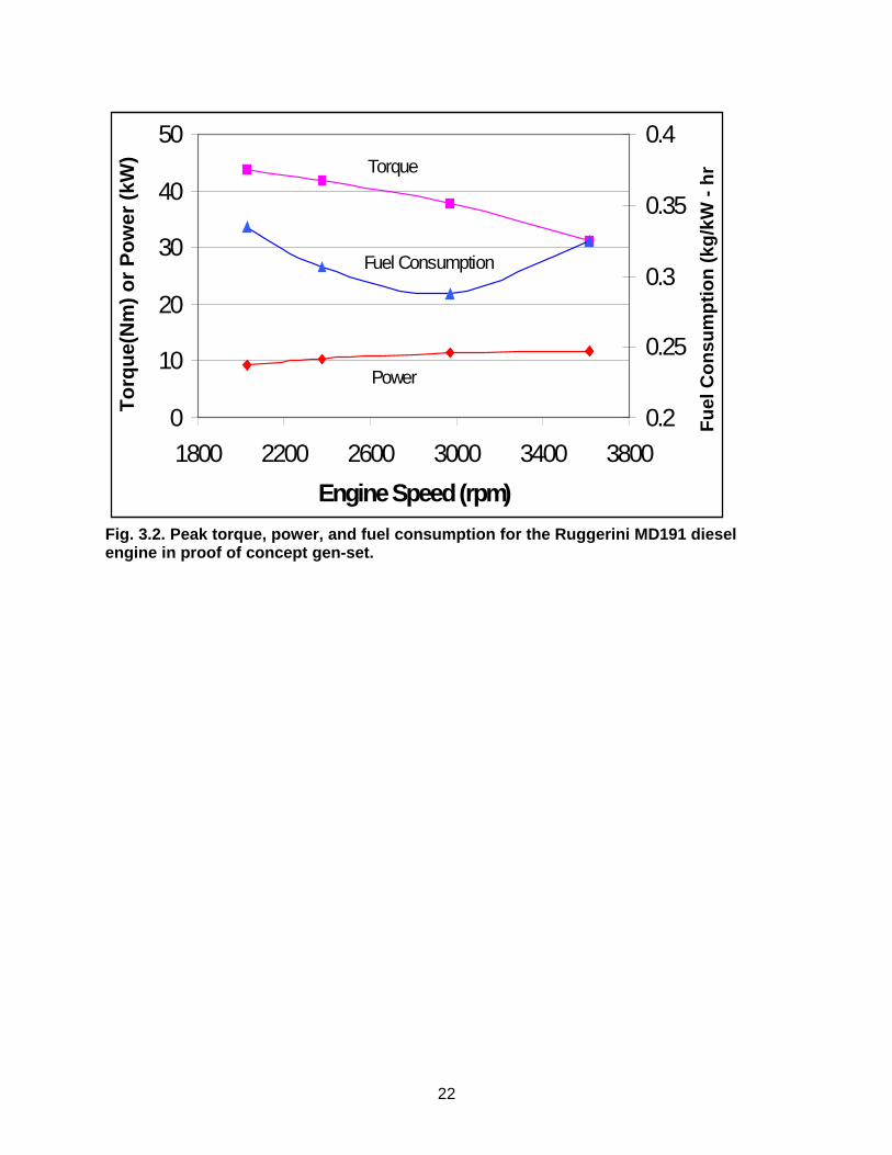
22
0
10
20
30
40
50
1800 2200 2600 3000 3400 3800
Engine Speed (rpm)
To
rqu
e(N
m)
or
Po
wer
(kW
)
0.2
0.25
0.3
0.35
0.4
Fu
el C
on
sum
pti
on
(kg
/kW
- h
rTorque
Power
Fuel Consumption
Fig. 3.2. Peak torque, power, and fuel consumption for the Ruggerini MD191 diesel engine in proof of concept gen-set.

23
�������������
��
�
��
��
��
��
��
��
��
��
��
��
��
��
���
����
� ��������� ��
�
��
��
�
�
�
��
��
�
�
�
��
���
������
������
������
������
������
������
������
�����
������
������
�������
�������
�������
��� ��
��� ��� ���� ���� ���� ���� ����
Fig. 3.3. Engine performance map of the Ruggerini MD191 engine used for the small gen-set.

24
Fig. 3.4. Ruggerini MD191 engine data at ambient and elevated temperatures and using JP-8.
Ruggerini MD191
20
22
24
26
28
30
32
34
1500 2000 2500 3000 3500 4000
Engine Speed (RPM)
To
rqu
e (f
t-lb
)
75 F
95 F
125 F
140 F
150 F
JP8
Full Load
Ambient Temperature
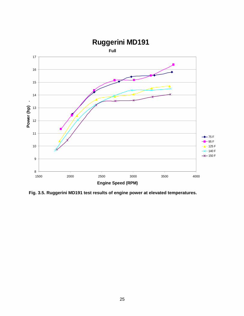
25
Fig. 3.5. Ruggerini MD191 test results of engine power at elevated temperatures.
Ruggerini MD191
8
9
10
11
12
13
14
15
16
17
1500 2000 2500 3000 3500 4000
Engine Speed (RPM)
Po
we
r (h
p)
.
75 F
95 F
125 F
140 F
150 F
Full
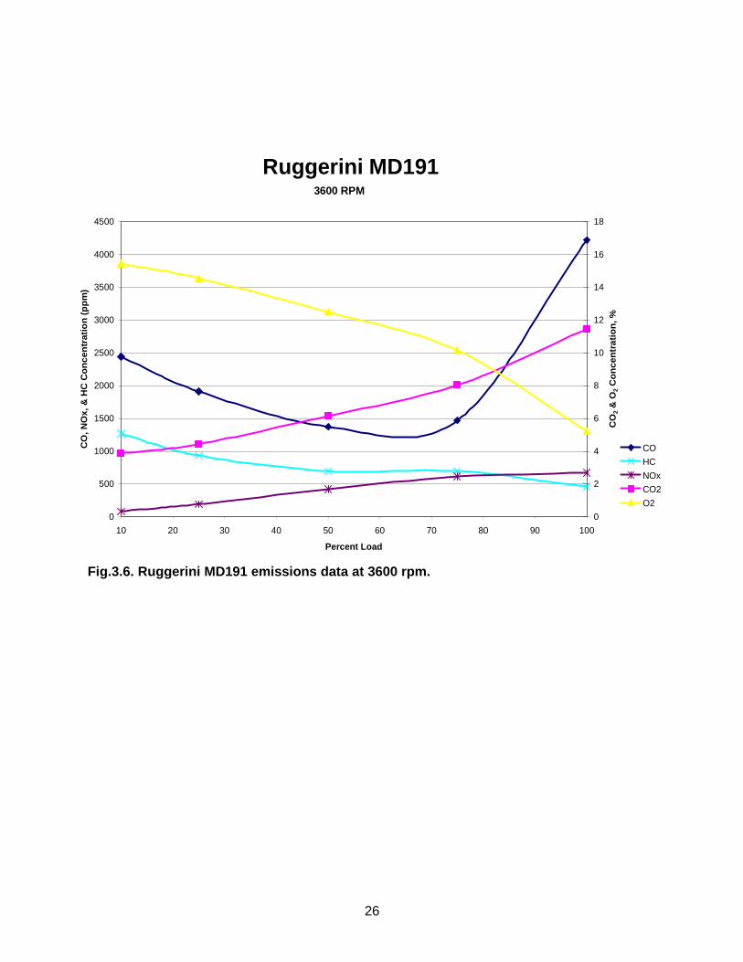
26
Fig.3.6. Ruggerini MD191 emissions data at 3600 rpm.
Ruggerini MD191
0
500
1000
1500
2000
2500
3000
3500
4000
4500
10 20 30 40 50 60 70 80 90 100
Percent Load
CO
, NO
x, &
HC
Co
nce
ntr
atio
n (
pp
m)
0
2
4
6
8
10
12
14
16
18
CO
2 &
O2
Co
nce
ntr
atio
n, %
CO
HC
NOx
CO2
O2
3600 RPM

27
Fig. 3.7. Wetstacking analysis showing the location where wetstacking is most likely to occur.
�������������
�
���
���
���
���
���
���
���
��
� �� �� �� � ���
�������������� ���
�
��
�
��
�
��
��������
��������
�������
��������
��������
��������
�������
��������
�� �������������������������������������������� ������������!���������������������������������������������� ��"������� ��� ��� � �

28
Small Engine / Alternator Design Match Approach
1500 2000 2500 3000 3500 40005
6
7
8
9
10
11
Factory engineUT Test engineAlternator
Ruggerini Engine / Alternator Power Out
Speed, rpm
Out
put P
ower
, kW
Fig. 3.8. Small Ruggerini MD191 engine/alternator design match approach.

29
Large Engine / Alternator Design Match Approach
1200 1400 1600 1800 2000 2200 2400 2600 2800 300040
50
60
70
80
90
100
110
120
Factory engineReqd Alternator
DDC D706LT Engine / Alternator Power Out
Speed, rpm
Out
put P
ower
, kW
Fig. 3.9. Large DDC VMM D706LT engine/alternator design match approach.

30
Fig. 3.10. PM alternator mounted to small gen-set Ruggerini MD191 engine.
0.0
50.0
100.0
150.0
200.0
250.0
300.0
350.0
400.0
450.0
500.0
1600 1800 2000 2200 2400 2600 2800 3000 3200 3400 3600 3800
Speed (rpm)
Vab
(V
olt
s)
Vab (Vrms)Vab (amplitude)
Figure 3.11. RMS and maximum voltage as a function of speed for the small PM alternator (before rewind).

31
Figure 3.12. Small PM alternator waveforms (after correcting phase wiring).


33
4. ELECTRICAL SYSTEMS DESIGN AND ANALYSIS This chapter describes the design, analysis, and lessons learned from the electrical systems, which includes the power electronics and digital control systems. 4.1 Power Electronics Design A robust and reliable power electronics system is one of the primary keys to the new gen-set concepts. The power electronics modules are an enabling technology that is growing in importance and offers a tremendous amount of flexibility. The increased flexibility brings about an increased complexity that must be carefully designed and implemented. The power electronics design specifications were: • Inverter to produce selectable frequency of 50, 60, and 400 Hz • Inverter to produce full rated power at
• 120V, single phase • 120/240V, “dual phase” • 120/208V, three phase
• Minimum weight • Maximum efficiency • Allow use of battery power to maintain output power during severe transients • Able to handle unbalanced loads in multi-phase operation • Excellent power quality • Simplicity A block diagram of the electronic power conversion system for the proof of concept generator set is shown in Fig. 4.1. The variable frequency, variable voltage produced by the permanent magnet alternator is diode-rectified to dc voltage, and an inverter is used to produce selectable frequency at a controllable ac voltage. The user is allowed to select single-phase 120V, “dual-phase” 120/240V, or three-phase 120/208V. Each of these voltage configurations can be generated at 50 Hz, 60 Hz, and 400 Hz. The power conversion system also incorporates a bi-directional dc-dc converter that can charge 24V batteries that are used to start the engine and to power auxiliary loads. The converter can also draw power from the batteries to help maintain the dc link during severe load transients. This design emphasizes weight reduction and simplicity over robustness and features. The determination of the dc link voltages is an important consideration that has many implications throughout the design and function of the proof-of-concept units. The lower dc link voltage of 350V is necessary to provide a full 120V (rms) AC. The lower link voltage is kept as low as possible to reduce switching losses, which increase as the lower link voltage increases. 350V dc was considered the minimum level in which a full 120 V AC signal could be generated. The maximum link voltage of 450V dc is selected to keep the link voltage within the operating limits of 600 V devices. 600V electronics were selected over 900V or 1200V components to minimize losses (which increase with increases voltage) and keep the costs lower. (As discussed below, the lower link design voltage had to be increased from 350V to 408V during final check-out. The text uses the design voltage of 350V when describing the functionality of the system.)

34
4.1.1 Asynchronous Boost Design The gen-set was designed such that the inverter can produce 120 Vrms line-neutral voltage for dc link voltages between 350 Vdc and 450 Vdc. During normal, unboosted operation, the alternator line-line voltage is rectified by the three-phase, full bridge rectifier D1 with conventional six-pulse rectification as shown in Fig. 4.2. During this mode, the boost rectifier is inactive and transistor Q1 is off for the alternator described in Chapter 3. The minimum desired dc link voltage of 350 Vdc corresponds to an alternator speed of 2800 rpm. The primary advantage of the asynchronous (or alternator) boost is to increase the operating range of the variable speed generator set. Without this circuit, the speed of the system could only vary between 2800 and 3600 rpm rather than 2000 to 3600 rpm. The variable speed operation is a key feature of the generator set system. When the DC link voltage produced by this normal mode of rectification is less than 350 Vdc (corresponding to a gen-set speed less than 2800 rpm), the asynchronous boost circuit becomes active to maintain the dc link voltage. The circuit that boosts the alternator voltage when the speed is low operates asynchronously with rotor position. When the boost is active, transistor Q1 turns on and effectively shorts out the alternator through the full-bridge rectifier D2 shown in Fig. 4.2. During this time, the three-phase full-bridge rectifier diodes in D1 block, and capacitor C1 supplies the inverter load. The current being supplied by the alternator ramps up due to this short and is limited only by the alternator leakage inductance. When Q1 turns off, the current then flows through the three-phase full-bridge rectifier D1 to charge C1. Transistor Q1 is operated as a DC current mode boost, and the diodes in D1 must be the fast recovery type because they are operated at the boost switching frequency. The diodes in D2 are commutated at the alternator frequency and therefore do not have reverse recovery requirements. The parasitic inductance of the path through D1 and C1 where the boost current flows when Q1 is turned off can cause a large voltage spike at Q1. However, the snubber composed of C2 and D3 offers a low inductance diversion path for this current and thus limits the di/dt to a value that will not produce damaging voltage spikes.
The alternator neutral and load neutral are connected to the center of two capacitors C3 shown in Fig. 4.3. The connection allows unbalanced load currents to flow through the alternator in parallel with the capacitors and eliminates the requirement that they have a low impedance at the fundamental frequency. The inductor L1 shown in Fig. 4.2 prevents what would be an undesired consequence of this connection. Without L1, each of the C3 capacitors would charge to the half-wave rectified line-neutral voltage of the alternator, which results in poor power factor and high crest factor in the alternating current. The asynchronous boost was implemented in the proof-of-concept gen-set instead of other possible topologies because it required only one additional active switch and, as the name implies, did not require synchronism with the permanent magnet generator’s voltage waveforms. Another possible circuit topology would be a full-bridge active rectifier instead of the passive rectifier D2 shown in Fig. 4.2. The advantage of the active rectifier would be a smoother input current from the generator and less switching noise. The disadvantage would be the six active devices and the additional control complexity to synchronize the active rectifier with the generator set speed and position.

35
4.1.2 Inverter and Output Filter Design A traditional full-bridge three-phase inverter composed of a 600V, 200A six-pack IGBT module Q2 (Eupec BSM200GD60LD) was controlled with a digital signal processor (DSP) to produce a pulse width modulated (PWM) output as shown by the schematic in Fig. 4.3. The PWM waveform is passed through a three-phase common-mode LC filter composed of L3 and C5 and a three-phase differential mode LC filter composed of L2 and C4 to achieve near sine-wave (<3% total harmonic distortion) waveforms in bench testing as shown in Figs. 4.4 & 4.5. The differential mode filter was designed for a corner frequency of 3.3 kHz, and the common mode filter has a corner frequency of 1.3 kHz. 4.1.3 Bi-Directional Converter Design The bi-directional power supply takes power from the link and converts it to 28 V to power 28 V auxiliary loads and to recharge the engine starting battery. The converter is able to provide 7 kW for less than 10 seconds or 1.4 kW continuously. When operating in this buck mode, the converter operates as a voltage mode half-bridge transformer coupled buck regulator with a current doubler rectifier. In boost mode, the converter can use the 28 V power from the battery to supply the dc link during load transients when the engine has not responded with sufficient speed to maintain the dc link above 350 Vdc. The selection of these two topologies was to minimize the energy storage requirements and transformer turns ratio such that it is of minimum size and weight yet able to provide enough ride-through until the engine can pick up the load. Several other bi-directional dc-dc topologies are available, but the one implemented likely required the minimum energy storage (inductors and capacitors) so as to keep the gen-set weight to a minimum. Full-bridge converters could have been used on both sides of the transformer T1 shown in Fig. 4.6, but these would have required additional gate drivers and control signals. Soft-switching (resonant) dc-dc converters have also been described in the literature, but most of these circuits require additional active switches or additional inductance and capacitance to create a resonance condition in the circuit. The advantage of soft-switching circuits is reduced switching losses and noise in the main circuit, with their main disadvantage being additional complexity, components, and increased switching noise in the auxiliary switches. For high voltage to low voltage operation, the dc link voltage is passed through an R-L link damper consisting of the two R3 resistors and L4 as shown in Fig. 4.6. This link damper prevents oscillation between the C6 capacitors of the bi-directional converter and the DC link capacitors C3 on the inverter (Fig. 4.3). The C6 capacitors serve as high frequency energy storage for power transfer in either direction and make up the reactive half of the half bridge converter with the Q3 IGBTs. To minimize the size and weight of the high frequency transformer T1, the Q3 IGBTs are driven at a 20 kHz frequency. Transformer T1 has a turns ratio of 2.8:1; this combined with the voltage halving of the half-bridge and a second voltage halving by the current doubler rectifier (body diodes of MOSFETs Q4 and filtered by L5 and L6) allows the Q3 IGBTs to be operated at a maximum duty ratio of 0.85 when converting 350V to 30V. For low voltage to high voltage operation, the boost mode was originally designed to activate when the dc link voltage falls to 340 Vdc, or 10 V below the nominal dc link voltage. When both of the Q4 transistors are on, transformer T1 is shorted and the battery voltage is applied to inductors L5 and L6. When one of the two switches is turned off, the input voltage plus the

36
energy stored in the inductor is applied to T1. Transformer T1 steps up the voltage, which is then rectified by the antiparallel diodes of the Q3 IGBTs. When both of the Q4 switches are off, any stored energy in inductors L5 and L6 is transferred through D4 to C7, which is then discharged by R2. Fig. 4.7 shows a bench test of how the bi-directional converter is able to maintain the dc link voltage under the extreme case of complete loss of power from the rectified alternator voltage. The dc link voltage dips from 350 V to 280 V for the case shown in Fig. 4.7, but the converter will operate under the less stringent requirements of maintaining the dc link during a short-term overload and not for a complete loss of power from the prime mover. 4.1.4 Analysis of Power Electronics System The power electronics modules are controlled completely by the control system that is described below. One of the key lessons learned in this phase of the project is that the power electronics and controls should be completely integrated. Therefore, the analysis and lessons learned for the power electronics and controls are combined and are given later in this Chapter. 4.2 Digital Control System (including Diagnostics & Prognostics) For the proof-of-concept units, a digital control system designed and developed at ORNL was employed. The control system has the task of operating the power electronics hardware in a timely fashion (from microseconds to minutes) to achieve the proper output and interface. The electrical output is measured and compensated every few microseconds, while operator inputs and engine speed are monitored several times a second. Other parameters like temperatures and oil pressures need only occasional checking. The primary criteria for the design of the control system in this phase were schedule and flexibility. Many of the features for this control system will not be necessary once the hardware and software requirements are better known. Since it is the software that interprets the functions of all the switches and other inputs, it is easy to change or update the control logic to match different conditions, engines, or even power electronics. The system was also designed to enable the addition of diagnostics and prognostics to facilitate field maintenance and repair. 4.2.1 Digital vs Analog Control As mentioned previously, the primary design criteria for the control system is that it handle all the demands placed on it from other components and that it be flexible and adaptable. The control of the power electronics could be either analog or digital and the tradeoffs are such that the better decision was not immediately obvious. The initial proof-of-concept power electronics contained both analog and digital control circuits. During the proof-of-concept phase it became obvious that the additional complexity of dual control circuits was problematic and the decision was made to use the digital controls exclusively. With digital control any changes could be easily implemented with a software change where analog control would require a redesign of the control circuits. Developing a system to both tune the analog control system to the second order output filters and also develop a digital control system doubled the effort when only one was needed. The digital system greatly simplified the electronic design (trading software for hardware) and simultaneously provided the flexibility required for the proof-of-concept system. This allowed the hardware to be finalized while the software approach allowed last minute changes anywhere in

37
the control system design. Thus the decision was made to use only the digital controls meaning that the entire control from the electronics to the output would be digital. Since the digital controls are software based, many new features and/or modifications can be added at any time via a software upgrade. If a new voltage or frequency or phase relationship is needed, it is easily performed by amending the software. Also the effects of controls can be changed to incorporate additional intelligence and or safety features. There is a trade off between digital and analog control. Analog systems are likely to be cheaper to produce in quantity, but control is hardware based making upgrades much more difficult and expensive in the long run. Digital controls can be software based and thus more flexible. While initial hardware cost may be higher and development times can vary considerably for both systems, it is felt that for complex systems such as this, digital is the way to go. For the proof-of-concept phase, the flexibility of the software controls was necessary. Over time, as more is learned about the system operation, software enhancements could be easily added in a digital system along with diagnostics and prognostics which could greatly aid the user in the field. The displays could be changed to meet changing demands, and a host of other features could be added or dropped with a simple software upgrade. This would be much more difficult if not impossible with an analog system. However, once the exact functionality of the controls is determined, analog control may be used successfully. 4.2.2 Hardware Requirements A user control and status display panel on the gen-set unit provides an interface to a digital control system. The controls were implemented on two Texas Instruments TMS320F6701 floating point Digital Signal Processors (DSP) on the Spectrum Daytona dual DSP card with a PCI interface. The entire control system is housed on a PC running under Windows 2000. In addition to this, a PCI interface card was designed and implemented to interface the DSP card via a 32-bit parallel port. This interface board (OrnlDas) contains eight independent 14-bit A/D converters that operate at 1.2µsec analog input to digital output and twelve more analog channel inputs that operate at up to 4µsec. An OrnlDas card also contains a dual UART (Universal Asynchronous Receiver / Transmitter) to communicate to the Front Panel displays via a standard serial link, four 16-bit D/As for analog control, and four 16-bit input and output digital channels. The control is split between the two DSPs on the Daytona card. The primary DSP, which can communicate with the OrnlDas card, performs all of the I/O with the rest of the gen-set. It also regulates the output voltage on a point-by-point basis. Other functions of the first DSP include control of the optimum engine speed for a given output power. The second DSP takes the analog and digital data from the first DSP and computes root-mean-square (RMS) voltages and currents, power levels, and power factors of the AC waveforms; the dc link, battery, and 28V auxiliary load voltages and currents; and the averages of temperatures, oil pressure, engine speed, etc. These results are converted to ASCII and are displayed on the screens on one or more of the display selections. All operator inputs on the display panel are routed directly to the primary DSP. It is this DSP that then interprets the information and decides on the “safe” conditions before controlling the rest of the system. All inputs must go through this DSP before affecting an output. This insures that contradictory information is handled correctly and dangerous situations are avoided. The only exceptions to this are emergency shutdown and the main power shutdown for obvious reasons.

38
4.2.3 User Interface The display panel allows the user to monitor phase voltages, currents, power, and power factor from a user digital display, shown in Fig. 4.8. The display shows the engine speed and the status of certain parameters such as oil pressure and temperature and intake or exhaust temperature. Output selection of 120 V/single phase, 240 V/dual phase, and 208 V/three phase are switch selectable as shown at the bottom of the picture in Fig. 4.8. The output frequencies of 50 Hz, 60 Hz, and 400 Hz are also switch selectable. Once the electrical output is energized, however, these switches are ignored to prevent false changes during operation and damage of the connected load. Fig. 4.9 provides a listing of all the information available on the various screens. The digital user interface was chosen to maximize the flexibility of the overall system by allowing for the display of large amounts of information in a simple, easy-to-understand format. The display screens are programmed to toggle and display different levels of information. It was felt that these displays would be sufficiently rugged and usable in the field to warrant full consideration in production units. 4.2.4 DSP Selection In this application, the DSP must do much more than simply drive the electrical power waveforms. Initially a TMS320LF2701 16-bit integer Digital Signal Processor (DSP) was selected because it was designed specifically to generate electrical power waveforms and has the following attributes:
• 30 MHz clock speed • Integrated Pulse Width Modulation (PWM) circuit in hardware • Onboard EEPROM for program storage without power • Inexpensive ($15 in quantities)
The limitation of this DSP is that it is an integer-only processor and in this application most of the computations need to be performed in extended precision with a floating binary point. The result is that this processor just did not have the processing power needed in this application. In addition, programming a floating binary point took an extensive amount of development time to insure that the placement of the binary point in every calculation did not overflow nor underflow. Overflow creates gross errors that generate wild unpredictable answers. Underflow, while not as drastic, produces loss of accuracy and when taking small differences of large numbers as in RMS calculations can also produce indeterminate results. Therefore, to program an integer DSP, one needs to know in advance the ranges of the data that are being calculated. After initial work with this 2701 DSP, it was realized that the programming effort was not only too demanding for our cost/schedule but also the DSP was not fast enough for all that was required. The decision was then made to use a TMS320F6701 floating point DSP which is a 32-bit processor capable of peak speeds of 0.8 GigaFlop [10^9 floating point operations per second]. The advantage here is the speed and the ease of programming in floating point arithmetic. The disadvantage is primarily the cost. The PCI card we are using for this project is a Daytona card made by Spectrum Signal and sells for ~$5000. It contains two DSPs with shared memory, ports for communicating with the outside world, and DMA (Direct Memory Access) between the two processors, the PC itself, and other onboard memories via three PCI bridges. Other disadvantages for this application are that it does not contain PWM hardware like the 2701

39
DSP, nor does it contain onboard EEPROM (Electronically Erasable Programmable Read Only Memory) for stored programs. The PWM is currently implemented in software via the interrupts, as there was not the time nor budget to implement a hardware version, which would be highly desirable. The EEPROM is available as an optional card but does not provide the capability to start execution of the stored program and must wait for the PC command to do so. Therefore there is no benefit to using the existing EEPROM until an auto-start feature is implemented. This means that until this feature is Windows to boot (about 2 min) before the system is ready to go. When the EEPROM can start automatically then the system will be ready to run in less than a second after power turn on. The digital control system is programmed with Texas Instruments C compiler Version 2 for these DSPs and goes by the name of Code Composer. It is designed specifically for this line of DSPs. It runs on the PC under Windows and has full debugging and profiling capability. While the optimizers did reduce program execution time by 20% or more, they did not always produce correct code. Another version of Code Composer also supports the 2701 integer DSP chip. This eases the code development considerably by making code development almost seamless. 4.2.5 Gen-Set Instrumentation The digital control system is required to monitor and control a host of analog and digital signals throughout the system. Most are listed here in outline form.
• Operator switches (Front Panel & output block)
o Master power on/off o Engine On/Off/Start o Power output On/Off o Panic Button shutdown o Battle Mode o Two display scroll controls o Voltage setting (120V, 240V, 208V) o Frequency setting (50Hz, 60Hz, 400Hz) o Local/Remote voltage sense o Master/Slave control
• Analog conditioning for sensing of: o Engine Oil Temp o Exhaust Temp o Oil Pressure o Exhaust Valve Sensor o Convenience Outlet Voltage Sense o Fuel Level o Intake Air Temperature o 3 Differential Output Voltage sense (3 locations) o 4 Output Currents (A,B,C,& Neutral) o Battery current o NATO current o Battery voltage o Link Positive & Negative voltages o Link Positive & Negative currents o 8 temperature locations in the inverter

40
• Digital Inputs o Front Panel Switches listed above o Engine throttle limits o Engine Speed o Inverter Over Current shutdown
• Digital Outputs o Front Panel
��Two 4x80 character displays ��Engine throttle control ��Display select ��Display power On/Off ��Analog multiplexer addressing ��Fault Light ��Electrical Output Energized ��Display select (Top or Bot) ��Display source select (DSP or PC) ��Hour meter ��Output power contactor control ��Select Local or Remote Voltage sense ��Select Display source (DSP or PC) �� Load banks control ��Engine starter ��Engine fuel valve ��Convenience Outlet contactor
• Inverter �� 6 IGBT gate controls ��Boost Enable for the generator ��Battery source output ��Reset inverter ��Shutdown inverter ��Temperature multiplexer control
All of the above analog inputs need to be conditioned for isolation, gain, offset, and frequency filtering. When the inverter is operating and supplying a load, the IGBTs (switching transistors) are turning on and off very large currents in less than two microseconds every eight microseconds or so. This creates a very large change of current flow in a very short time and can create EMI and electrical noise throughout the system. Therefore proper design and shielding of the electronics is absolutely essential. 4.2.6 Control Flow The PC in the prototype system merely hosts the DSP card. It runs the compilers and other overhead functions for the software development of the DSP code. In the future, the diagnostics and prognostics can be implemented on the PC as described below. Also there can be plenty of room in the PC for maintenance manuals and other important documentation and useful information. The first DSP processor is focused upon only those functions that provide interfacing with the outside world: electrical power waveforms, switch inputs, safety criteria, and data acquisition. The second processor communicates with the first via a dual port RAM. It does not have any

41
outside world access. Its function is to do all the “off-line” compute intensive functions for display purposes such as RMS and power factor values. Full code listings for the DSPs (about 6000 lines of C code are listed in the Appendix) are be summarized here.
DSP #1 There are three main sections to the code on DSP #1:
1 Startup loop (with DSP initialization) 2 Power loop (and its initialization) 3 PWM interrupt routine
Upon code entry (system power up) and after every fault, an initialization routine is called, it initializes all hardware both on the DSP card and all the external hardware such as the ORNL-DAS card, the Front Panel Display, and the Inverter. It then drops through to the Startup Loop.
Startup Loop This loop runs continuously whenever the system is turned on but electrical power is not output. Its primary purpose is housekeeping and to respond to operator input such as starting the engine, setting parameters from operator input switches, and calling for power output. This loop takes about 30 µs to execute due to delays, which are implemented to synchronize the data acquisition. Power Loop This is the loop that is in effect when electrical power is being produced. It looks at the state of the output waveform and calls for appropriate corrections. It also defines the PWM interrupt routine values for the inverter control. This loop takes about 40 us to execute when fully optimized by the compiler. Since the PWM cycle takes 50 us, this insures that everything can get updated and collected in time for the next PWM cycle. The PWM data are updated twice in this loop so that each half of the PWM cycle can be independently controlled. PWM Interrupt This is an interrupt routine that is called 160,000 times a second to set the state of the IGBT (Insulated Gate Bipolar Transistor) gates (the power switches) as well as to trigger and accumulate the data acquisition of the output voltage and current values. These analog-to-digital (A/D) conversions are timed to fall exactly in the center and end of each PWM cycle (every 25 µs) to synchronize the acquisition of the output voltage and current measurements with this cycle. The remaining interrupts fall at random times and in random order within the 25 µs interval depending upon the adjustments needed for output waveform control. In the prototype system, the PWM driver for the IGBT gate drives was implemented in software because of cost and schedule. However, one third of the function of DSP #1 is consumed with handling the interrupts for this function. If this PWM function was handled in a hardware circuit such as a programmable application-specific-integrated-circuit (ASIC), then the programming and overhead could be greatly reduced, and this section of the code could be eliminated. DSP #2 This processor runs a single loop. It looks in the Dual Port Ram for updated information and calculates all the average, RMS, statistical, and other peripheral results of all the analog and digital inputs. It then converts the results to ASCII and outputs them to the displays via the Dual Port RAM.

42
ORNL-DAS Interface This is an in-house designed card that plugs into a PCI bus in a PC for power. All communication to/from the DSP #1 is performed over a bi-directional 32-bit high-speed interface. This card is responsible for conditioning all the input/output to the rest of the gen-set. All analog signals are treated as differential and are buffered, scaled, offset, (some are multiplexed) and converted to/from digital format. All digital signals are buffered and converted to/from TTL (5 Volt) and CMOS (12 Volt) level signals. In addition, a dual UART (serial communications port) is implemented on this card to be able to communicate to the front panel displays. There is also conditioning circuitry for an encoder input as well as for engine tachometer input. 4.2.7 Additional Features There are additional features that were not fully implemented in the prototype due to cost and schedule but have been designed into the control system. These include the option to add pre-heaters to the intake air to reduce wet stacking. This would elevate the engine temperature as well as provide additional load to stop the wet stacking. This additional load would be applied when the engine is at a low speed (inefficient mode) so that an extra power drain on the engine to run the pre-heaters would be almost free heat. Another feature is the master/slave mode of operation. This feature allows automatic parallel load switching and operation of multiple gen-sets. Since this system is one of a kind, it was not possible to implement this feature. However, the process for this implementation has been discussed in earlier reports. In addition, there are several unused digital and analog inputs and outputs that can be connected to additional sensors, switches, and outputs as the need arises. One addition that would improve the output waveform quality would be to have two sets of output filters for the power lines instead of just one. One filter would be tuned to 50/60 Hz operation, and the other filter would be tuned to 400 Hz. An extra output would be used to select which filter would be in use. 4.2.8 Diagnostics & Prognostics One of the primary reasons for basing the digital controls in a PC is to allow the DSP to monitor, collect and store system data to be analyzed and used for system diagnostics. Our approach to the diagnostics is to collect and store the data and then analyze the data in the background to predict impending failure. The system is designed to include a data acquisition system in order to collect system information. Data that can be monitored and used for diagnostics are shown in Fig. 4.10. Our design approach is that the diagnostics system must not overwhelm the remainder of the system and must operate in background unless failure is eminent. Large numbers of monitored parameters can lead to reliability concerns if the sensors themselves fail. Therefore, the number of additional sensors and monitored parameters must be kept to a minimum. For the system to be able to correctly diagnose and predict failure, the system must record these failures and “learn” from them. Insufficient time has lapsed for the failure modes to be learned so these algorithms will need to be developed in the future. 4.3 Analysis of Power Electronics and Digital Control Systems The use of power electronics in this system is one of the keys, if not the key feature of the entire AMMPS proof-of-concept phase. The digital controls are the DSPs and associated software

43
along with all the conditioning circuitry that drive the power electronics hardware. The analysis provided herein is an analysis of the power electronics modules and the digital controls system. More information is given later in the report about the implications to the system using power electronics. The power electronics and digital controls were clearly the most expensive and tedious subsystems of the proof-of-concept unit. These systems were designed to be scaled up in the medium and large units. The controls for all three units are essentially the same and with minor software adjustments can drive the hardware for all units and would be interchangeable in the field. The power electronics and controls both function basically as designed. Each design aspect described above is functioning at some level. Some of the features that were designed into the electronics do not perform as well as hoped. Several changes and modifications were made during the integration of the electronics and controls that are described here. Both the electronics and controls were tested independently from each other before they were integrated together and both functioned quite well separately. It is our opinion that the problem areas are well understood and can be solved with additional time to integrate and adjust the power electronics and controls. 4.3.1 DC Link Voltage The DC link voltage was designed to operate between 350 and 450V. The lower link voltage should be kept as low as possible to reduce losses and still produce a full 120V sine wave AC signal. During the integration of the power electronics and controls, it was determined that 350V was not sufficient to produce a full 120V signal in the prototype system. The link voltage is set with a resistor in the power electronics module which was modified to increase the minimum link voltage to 408V. This improved the output waveform significantly but, as will be described later, did not completely cure the problem. It is our belief that the interface between the electronics and controls need further modification to fully resolve this issue. The losses in the circuit may be greater than anticipated but circuit losses are not considered the entire reason for the increased link voltage. As previously described, the battery boost circuit is designed to maintain the DC link when the link drops below 340V. When the link voltage was increased from 350V to 408V in the alternator boost, however, the battery boost circuit was not modified. Therefore, the DC link must drop to 340V before the battery boost circuit is active. The larger than anticipated gap between the lower link voltage and battery boost causes the transient load response to suffer. However, the battery boost has been shown to be effective, and it is our opinion that once the voltage gap of this circuit is corrected the usefulness of this circuit will be fully realized. 4.3.2 Electrical Noise and Noise Suppression Filters and capacitance are used to eliminate noise and improve the output waveform but contribute directly to the weight of the electronics. In this design, a low weight was emphasized so additional filters were kept to a minimum. However, during the integration and testing of the power electronics and controls, the noise turned out to be greater than anticipated forcing the use of additional filters. One filter was used to eliminate switching noise rather than use two filters tuned to 50/60 and 400 Hz to improve the waveform. This issue will be discussed later in the report as a lessons learned and in the performance results.

44
4.3.3 Alternator Boost Circuit The permanent magnet alternator output voltage is directly proportional to rotational speed. The actual voltage delivered may drop due to its internal impedance, which is on the order of several ohms. The small alternator coupled to the Ruggerini MD191 engine is designed to output sufficient 3-phase voltage in a trapezoidal waveform such that the rectified voltage to the DC link is 500 Volts DC at 3600 rpm under no load. By trial and experience, the boost enable limit for the small alternator was set at 408 volts DC (no load). This can be significantly improved upon with further modifications to the circuit. Under normal operation, the DC link would be about 408 volts at 2940 rpm. Any time this link voltage drops below 408 volts and the output power is below 6 KW, the power electronics is set to enable the voltage boost mode, which permits the continued synthesizing of 120 volts AC output even at low speed. The boost mode is designed to maintain the link at 408 volts but anomalies in the prototype system allow this voltage to sag down to 388 volts under full load. Thus at loads below 7.5 kW (about 2940 rpm), the small gen-set alternator is operating in the voltage boost mode. In future designs, a better performance match between the alternator, power electronics and digital control would permit lowering the boost enable limit closer to the ideal 350 V on the DC link. There was insufficient time in the prototype program to implement the necessary changes. The changes needed are understood and can be implemented in subsequent designs. During the electrical assembly check out, the boost mode was observed to exhibit excess high frequency electrical noise. The radiated noise interfered with the digital display and control system, which may shut down the gen-set. Enclosing and shielding the power electronics and cables eliminated this effect. Separating and/or shielding the noisy electronic parts from the sensitive parts can eliminate the noise interference problem. But, if an electrical noise problem should persist, a long-term solution may involve other redesign options. One is to use softer (quieter) rectifier boost switching techniques. Another is to use higher voltage electronic components (i.e. 900 or 1200 volts) and eliminate the need to boost but this lowers system efficiency. Another design option is to integrate the alternator and boost circuit into the same metal alternator housing. This would separate the sensitive display and control circuit boards from this EMI noise source, which would produce a more robust design. In addition to matching the alternator and engine continuous power curves, it would be prudent to review the alternator and engine torque curves. When the alternator is operating in the boost mode, its torque demand is greater at low speed than without boost enabled. This should be taken into account when designing the alternator and selecting the optimum variable speed operating line. Sufficient engine torque headroom should be allowed so that the engine has reserve torque to accelerate to the desired speed during transient demand load increases. We want to avoid stalling the engine under transient load changes. The small gen-set control system also employs transient battery boost of the DC link to off-load the engine and allow quicker acceleration to the desired speed. With this offloading of the engine the acceleration takes place in a matter of a few seconds. Without the offloading, the engine stalled out under sudden heavy power demands.

45
4.3.4 Digital Controls The digital control system has been shown to be a very flexible method of control, which is highly advantageous during this phase of the program while changes are still being incorporated. The primary drawbacks are the need for extra processing speed and the long start up time to boot the PC which hosts the DSPs. Processing speed can be increased once the PWM circuits are built into hardware (or processor speeds increase). The long start-up sequence is solved once the EEPROM option for this DSP is available. A more reasonable solution may be that once the controls have been finalized and tested, the hardware required to run the controls can be modified to optimize the system. For example, rather than use a PC as host, the DSPs can be run by a digital controller or other system. 4.3.5 Display The displays used have proven to be a very effective user interface during the proof-of-concept phase of the project. Large amounts of information are conveyed - the displays are simple to use, relatively easy to modify, and have worked well in system diagnostics. The primary drawback of the displays is that they do not perform well in direct sunlight. However, our experience is that any shade at all is sufficient to read the displays. Given the advantages of these devices, this seems a reasonable tradeoff to make. If visibility is still an issue, the front panels are designed to accept an LCD display, also. These displays may or may not need a software change to operate. 4.4 Lessons Learned from Power Electronics and Digital Controls Several lessons were learned during the integration and testing of the power electronics and control system. Although these lessons were learned during the proof-of-concept phase, they need to be fully appreciated to avoid duplication in subsequent phases of the program. During the proof-of-concept phase, both the power electronics and controls system went through a major re-design before the components were integrated together. In our case, the power electronics were designed and fabricated at E&M Power while ORNL developed the digital control system. Integration of those two systems is critically important and not trivial. Specific lessons learned regarding the controls, power electronics, and integration of these systems are as follows: • Power electronics and the control system must be completely integrated in order for this
system to function. In our opinion, these systems need to be developed in parallel with each other in close proximity with each other. Close coordination and constant exchange between the two is essential to insure efficient, effective, robust, and timely design. There is a lot that has to be coordinated and having one part designed at a different location generates too many errors in coordination.
• Reliability of the PE is a concern and must be built in from the outset. Issues such as proper
thermal management, vibration control, and protection from elements need to be considered in the overall system design. We advocate the use of a modular design and sufficient separation between components to facilitate thermal management and ease of repair. Moreover, the power electronics design itself needs to factor in reliability issues.
• Electrical noise and interference are prevalent everywhere. Proper and redundant noise
suppression is required.

46
• Alternator boost circuit improves flexibility and increases the speed range of the alternator and thus the system, but the long-term reliability of the system is not verified. Alternative PE topologies may be used to avoid this feature.
• Need multiple tuned filters for 50/60 & 400 Hz. This will increase the system weight but
noise suppression is vitally important to the proper operation of the system. • Noise on DC link ruins system. • While floating point DSPs are expensive compared to integer DSPs, the development time
for integer DSPs is considerably higher. Weighing the cost of development vs. hardware costs, there would have to be a very large production volume to warrant the extra development effort for integer DSP use. In addition the time-to-market for integer DSPs development is considerably longer due to the floating binary point requirement. It may be prudent to develop a floating point DSP initially and then convert over to an integer DSP system as time and money permit. The integer DSP evaluation module (EVM) we first used was $750 while the floating point PCI card from Spectrum Signal is $5K. But it contains two DSPs, while the integer EVM contained only one DSP. Any system of this magnitude in control will require at least two DSP’s (or at least one DSP and one PC.) The DSP is necessary to control the inverter output voltages and currents. The remaining calculations can be performed efficiently by today’s PC specifications. The communication between the two must be efficient and timely which means either shared memory or DMA data transfers.
• The inverter needs to be designed in such a way that any signal from the controller cannot
create a conflict or an over-current situation. This will prevent spurious signals or loss of control from causing any damage to the system. For example, the logic needs to be designed such that the same top and bottom leg of an output cannot be active at the same time and in addition have the dead-time built into hardware, even though the control signals may call for it. Also to prevent having a leg turned on and then having the control system fail for some reason leaving the leg turned on, a watch-dog on the inverter can be activated by a lack of active control signals and shut the inverter down before any catastrophic situation can occur. Our system has a watch-dog time set to 150us. Therefore, if the control DSP does not trigger the watch-dog within this time period the gate drive power to the IGBTs is turned off immediately which turns off the output power and the main power contactor responds about 20ms later.
• All sensors need to be isolated to prevent false offsets. • All digital logic needs to be level rather than edge triggered for noise immunity. In addition,
the level trigger may need to be extended and highly filtered to prevent false triggering. • All analog inputs need to be differential to reduce noise from the inverter. • All power cables need to be well shielded, twisted, and kept short to reduce noise emission.
The boost circuit used to increase the permanent magnet generator voltage output at a given engine speed used the inductance of the generator as part of the circuit. This meant that switching noise is being generated in the power leads to the generator and must be well shielded.

47
• Analog sampling of the output voltage and current, needs to be synchronized with the PWM generator. The effect of the small ripple produced on the output can be eliminated with this approach. Otherwise this variation will look like noise and make it much more difficult to regulate. In this system the output is sampled precisely at the beginning and middle of the symmetric PWM signal and the last two of these values averaged for the most recent value used in the calculation.
• The TMS320F6701 is capable of running the 160,000 interrupts per second to generate the
PWM signals for all six IGBTs and A/D sampling. This uses about one third of its processing capability, leaving the remaining two thirds for the executive. It would be most desirable to generate the PWM signal in hardware for robustness. This would also allow a faster response for the executive to calculate corrections to the output waveform and would provide a better output waveform quality.
• The reaction of the output magnetics at startup required the control system to start the PWM
frequency at 50 kHz and ramp it down to the operating 20 kHz frequency. Otherwise a resonance in the magnetics was excited causing an over-current shutdown in the inverter. This startup ramp would be very difficult to do with the conventional analog version PWM from a triangle wave generator, but was easily performed with the digital system.
• The inverter has four current sensors on the output lines (A,B,C & Neutral phases) for over
current protection. Since they are located before the output filter they will include the currents which go into the filter capacitors and not the output load. This interferes with measuring the load currents and power factors. In principle this can be calculated out of current measurements, but it is not an easy nor accurate task. If accurate current and power factor measurements of the load are desired, then it would be best to include current sensors on the output terminals of the gen-set.
• Surges on the battery such as starting the engine can cause momentary dips in the power to
the computer and the other low voltage components. This can lead to outages in the computer causing it to reboot and start the process all over again. Therefore the computer power supply may require some kind of uninterruptible power supply (UPS) for these occasions. Since these outages are usually less than several seconds, the UPS does not have to provide much energy and can be accomplished with some large capacitors. Dropouts on our system last for about 30ms for computer turn on and about 100ms for engine start.
• If using a standard operating system (OS) like Windows, then one needs to orchestrate the
power management to the system to last for a long enough time to allow orderly shutdown of the system (for the OS to go through it standard shutdown procedure) and prevent disk write errors.
• Protection needs to be provided for shorted outputs. If an output is shorted then the PWM
control signal to the shorted phase becomes a voltage boost to the generator. In this case, the voltage generated on the link can exceed safe limits and possibly blow the IGBTs and other components as well. This applies as well if using one or more of the phases as a return path for single or dual phase operation, a short (ground connection) on these phases will cause an effective boost in voltage in the generator leading to a shutdown due to over

voltage/current. Most loads are likely to have the common connected to ground. Therefore the neutral return should be designed to handle the current for the common return in all cases.
• For electrical noise immunity of the generator boost circuit, it may be best to enclose the
rectifier/boost circuit as part of the generator and just run the 3-wire (plus, minus, & neutral) DC power out of it to the link.
• During the course of this phase, ORNL altered the process of cooling the electronics. We
originally had mounted the electronics in boxes attached directly to the engine shaft beyond the alternator. This was done to provide as much cooling air as possible. We altered our approach and moved to a passive system where the electronics were not directly cooled with the air but heat sinks were used and the cooling air removed heat from the sinks. This was done to reduce the vibration and contamination of the electronics. We feel this is still the proper step and in fact, now advocate the use of a modular design of all systems in the gen-set. More attention will be given to this issue in following sections of the report.
• The neutral line was a continuous connection between the common on the generator
windings through the system to the earth ground. This was intended to reference the entire system to earth ground and make for a simpler and safer system. However, since the link was only regulated between the plus and minus rails, there was no control on where the neutral voltage ended up in relation to the plus and minus rail voltages. Future designs can correct this problem by using two voltage regulation circuits instead of the one used in this design—one for the plus rail to neutral and one for the minus rail to neutral—and regulating them independently. This would simplify the control and allow full voltage output swings with less rail-to-rail voltage. An alternate approach is to generate this neutral reference with a fourth inverter leg and do away with the neutral line from the generator. This approach would not provide a continuous connection back to the generator but might be simpler to design in some applications.
48

49
DiodeRectifier/
BoostConverter
SelectableOutputInverter
BidirectionalBuck/BoostConverter
28 VdcAuxiliaryLoads
Two 12 VBatteries in
Series
Power Supplyfor Controllerand PowerElectronics
2000-3600 rpm3 phase,250Vac
- 450Vac
28 Vdc
350 Vdc - 450 Vdc
120 Vac, 1 ph.120/240 Vac, dual ph.
120/208 Vac 3 ph.DieselEngine
PMAlternator
50/60/400 Hz.
CommonMode and
TransverseMode Filter
Fig. 4.1. Functional block diagram of power conversion components in generator set.

50
L1C1
a b cAlternator
DC Link350 Vdc -450 Vdc
R1
C2
D3
D1
D2
Q1
N
Fig. 4.2. Schematic of gen-set boost rectifier.
Q2C3
C3
L2
L3
C4
C5
A B C N
CommonModeFilter
DifferentialMode Filter
DC Link350 Vdc -450 Vdc
Alternator Neutral
Fig. 4.3. Schematic of gen-set inverter and filters.

51
Fig. 4.4. Pre- and post-filtered line-neutral output voltage waveforms from the proof of concept gen-set.
van
vbn
vcn
Fig. 4.5. Filtered line-neutral inverter output voltage waveforms.

52
L5
DC Link350 Vdc -450 Vdc
C6 Q3
Neutral
Q3C6
T1
28V batteryand
auxiliaryloads
L6
R3
R3
R2
L4
C7C8
Q4
Q4
D4D4
Fig. 4.6. Schematic of gen-set bi-directional converter.
TT
T
���
��
1) up current cmd: 5 Volt 1 s 2) link voltage: 50 Volt 1 s
dY: 74.0 Volt dX: 188 ms Y: 353 Volt
vdc
Boost Command
Fig. 4.7. DC link voltage maintained by boost from bi-directional converter upon loss of voltage from prime mover.

53
Fig. 4.8. Small gen-set user interface and display panel (top half of picture) and field output connections and voltage configuration and frequency selection switches (bottom half of picture).

54
--------------------------- | Aph 120V 20A 2400W | Top Mode 1: normal display | Bph 120V 20A 2400W | Three phases at a glance | Cph 120V 20A 2400W | | 400Hz 208V/3p 7200W | --------------------------- --------------------------- | Xph 120V 20A 2400W | Top Modes 2,3,4: Individual output | 1.00 PF 00.0% THD | power, detailed data by phase | 33% Total Load | | 400Hz 208V/3p 7200W | --------------------------- --------------------------- | Lnk 225V 100A 2400W | Top Mode 5: Link information | 225V 100A 2400W | Internal information | Tot 450V 100A 4800W | | Neutral 50A | --------------------------- --------------------------- | Inv -30 -30 -30 -30F | Top Mode 6: Inverter & | T’s -30 30 30 30F | Thermister temperature throughout | Accel: Top Limit | inverter and output filters | | --------------------------- --------------------------- | 3600 RPM 100.0 Gal | Bot Mode 1: Engine parameters | Oil: 35 PSI 180F | Engine measurements | InT: -100F Exh: 150F | | Local VSen Btl-Shrt | --------------------------- --------------------------- | Batt: Good | Bot Mode 2: Battery/NATO plug | 24.0V +100.0A 2400W | DC power at a glance | Nato: | | 24.0V -100.0A 2400W | --------------------------- --------------------------- | Error: | Bot Mode 3: Error | None | Error output screen | | | | --------------------------- --------------------------- | Use top disp switch | Bot Mode 4: Manual | to change Eng Speed | Manual engine speed control | Set speed: 3000 RPM | Disabled in final version | Act speed: 2000 RPM | --------------------------- --------------------------- | Engine Settings: | Bot Mode 4 alternate: Manual | Output Power On! | Shows speed called for and | Set speed: 3000 RPM | actual speed of Engine | Act speed: 2000 RPM |
Fig. 4.9. Information currently available from display screens.

55
Figure 4.10. Data monitored in the small AMMPS gen-set.
Fuel Tank
AlternatorPower
Electronics
BatteryNATO Plug
BATTERY VOLTAGEBATTERY CURRENTBATTERY VO LTAGEBATTERY CURRENT
NATO PLUG CURRENTNATO PLUG CU RRENT
RMS �A VO LTAGE �A VOLTAGERMS �B VO LTAGE �B VOLTAGERMS �C VOLTAGE �C VOLTAGERMS �A CURRENT �A CURRENTRMS �B CURRENT �B CURRENTRMS �C CURRENT �C CURRENTRMS NEU. CURR ENT NEU. CURRENTOUTPUT POWERINVERTER TEMPS (8)�A POWER FACTOR�B POWER FACTOR�C POWER FACTORREM OTE / LOCAL SENSE
FU EL LEVEL
RECTIFIED VOLTAGERMS ( +) LINK VOLTAGERMS (-) LINK VOLTAGERMS ( +) LI NK CURRENTRMS (-) LINK CURRENTTEMPERATURE
SHAFT ANGULAR VELOCITYSHAFT ANGULAR VELOCITYVALVE (1) POSITIONOIL PRESSUREOIL PRESSUREOIL TEM PERATURECOOLANT TEMPERATUREEXHAU ST TEMPERATURE
FrontPanel
BATTLE MODE STATUSHOUR METER READINGFREQUENCY MODEEMR. STOP BTN. STATU SCIRCU IT BRKR. STATUSVOLTAGE MODE
NOTE:
39 SHARED MEMO RY PARAMETERS14 ANALOG SIGNALS
Engine LOAD


57
5. SYSTEMS INTEGRATION This chapter described the integration of the mechanical and electrical systems into a working proof-of-concept generator set. The specific technologies included are those which transform the working “mule” into a functioning gen-set. Issues such as frame and enclosure design, acoustics, and airflow are all addressed. 5.1 Frame & Enclosure Design The frame and enclosure of is an important contributor to several key features of a generator set, specifically: • Weight • Acoustic signature • Vibration and shock • Airflow and cooling • Electro-magnetic Interference (EMI) • Protection and ruggedness The primary criteria for designing the frame and enclosure for the proof-of-concept unit were to: • minimize the weight • minimize acoustical noise • provide adequate cooling • EMI shielding • ease of fabrication • cost • schedule 5.1.1 Enclosure Material Several lightweight materials (specifically, aluminum, inexpensive fiberglass composites, and more expensive carbon composites) were considered for the skid and enclosure. Aluminum was selected as the best choice for the structural components due to its low weight and cost, ease of fabrication, availability, and EMI shielding. For a small number of prototype units, aluminum is the material of choice. No additional conducting material was needed for EMI shielding, as might be the case for non-metallic enclosure material. For large numbers of production models, the use of inexpensive composite materials could be advantageous but these materials were not cost effective or conducive to our schedule for the proto-type units. 5.1.2 Skid-Based Housing Design The skid base is welded aluminum. The enclosure is bolted aluminum panels with five access doors. The proof-of-concept unit was designed to withstand a 6 mph "hump" test and a 1 ft drop test. Finite element stress analyses of the skid under quasi-static shock load combinations were performed. The skid was mass loaded with the major components for these stress analyses. The stress analysis showed that small gen-set skid was satisfactory as originally designed. For the large gen-set skid, some areas were reinforced based upon similar analyses.

58
Photographs of the small gen-set skid and housing configuration are shown in Figures 5.1 through 5.4. The small gen-set housing is 49.0 inches long by 31.3 inches wide by 30.1 inches high. The weight is about 524 lbs dry and 576 lbs wet. The general sequence of hardware from front to rear is fuel tank, engine alternator, power electronics, computer and display. The rear end of the alternator is inserted into the power electronics box and sealed so that the alternator-cooling fan can draw air through the electronics first before cooling the alternator. The exhaust silencer is mounted on the left side of the engine and exhausts out the top at the fuel tank end of the housing. A pair of 12-volt batteries are located in a battery box mounted to the skid on the silencer side of the engine. A good deal of the electrical components such as contactors and relays are mounted on the skid or within the housing but not necessarily in a protection box. Two double-hinged doors are located on each side of the housing for maintenance access. Three small doors at the rear end of the gen-set provide access to the computer, electrical outlet connections, and the control display. Most of the external housing walls have an interior lining of 1/2-inch thick acoustic foam insulation Soundcoat Co. FF40JM02. Some interior baffling also has the foam insulation. 5.1.3 Skid / Housing Lessons Learned The lessons learned from the fabrication of the skid and housing are listed here. The explanation for these lessons has been presented in the previous section. • The small gen-set housing is most likely too small. The next design iteration needs to be
larger. • The housing needs to be partitioned into heat-sensitive and heat insensitive compartments.
A larger housing would greatly simplify the hot/cool partitioning. • Modularize electrical subassemblies in boxes for cleanliness, EMI shielding, and simplified
maintenance and repair. Ease of access to key components is important for repair. External casing sides should be hinged on the bottom in key areas where access is needed. This would allow the side to fold down providing easy access without having to undo too many screws.
• Larger openings and greater airflow volume may be needed for increased cooling. • Aluminum is a good material for limited volume production. Composites may be attractive for
large production runs. 5.2 Acoustics The noise goal for all proof-of-concept generator sets (65 dB-A at 7 m) is especially difficult for the small units with noisy, small diesel engines that run at higher speeds. The engine chosen for the small proof -of-concept gen-set is the Ruggerini MD191, a two-cylinder, air cooled, diesel engine typically running at speeds of 2000-3600 rpm. Initial measurements under non-ideal conditions at the University of Tennessee-Knoxville showed the engine had sound levels in excess of 100 dBA, although open-field readings of the same engine were about 80-85 dBA at

59
7 m. In other words, the engine chosen for the small units was just about as poor a choice as possible from a noise standpoint. The effectiveness of using passive noise abatement techniques was debated and active noise cancellation (ANC) was briefly considered. However, ANC techniques were abandoned due to their high cost and availability concerns. Relatively positive results were realized with the standard noise reduction techniques of a quality muffler and a sound absorption foam envelope. Initial acoustic tests were conducted on the small gen-set operating in the automatic variable speed control mode under loads from zero to 8 kW. The results are shown in Figure 5.5. The acoustic tests reveal that in using the passive noise abatement strategy with 1/2-inch of foam, the gen-set noise can be reduced to between 62 and 73 dBA at 7 m at loads ranging from 0 to 8 kW and at speeds from 2200 to 3220 rpm. The sound pressure level can vary 5 to 6 dBA due to direction alone. The fuel end of the gen-set is quietest where as the throttle side of the gen-set is the noisiest. Most of the noise comes from the engine cooling air inlet on the throttle side. Even though this inlet has somewhat of an indirect airflow and noise path, additional work is obviously needed at this opening. A rule of thumb is that diesel engine noise increases about 6 dB per 1000-rpm increase in engine speed. These acoustic tests show a general trend for the enclosed gen-set of about 3 dBA noise increase per 1000 rpm speed increase, and about 0.7 dBA noise increase per 1 kW output power increase. The TQG noise requirement is 70 dBA at 7 meters. The AMMPS gen-set design goal is 65 dBA at 7 m. The lower noise levels were achieved in some directions at the lower power and speeds. To reach the new goal under all conditions, additional work is necessary to reduce the acoustic emissions to lower levels especially at high-speed and high power operation. This effort entails airflow, heat rejection, and acoustic design compromises. High quality hospital-grade mufflers were modified by EM Products Division of Phillips & Temro Industries to fit within the available space of the small and large gen-sets. The high-grade silencers for stationary applications are generally quieter but heavier than standard automotive silencers. In general, there is a volume and weight-noise trade-off. Larger volume and heavier mufflers tend to be quieter than smaller and lighter ones. The hospital-grade silencers have acoustic attenuation ranging from 28 to 40 dB over a 63 to 8000 Hz frequency range. For reference, the average attenuation is 12 to 18 dBA for a standard industrial-grade silencer, 18 to 25 dBA for residential-grade, and 25 to 34 dBA for critical-grade. The small gen-set muffler (Cowl JHS-15X-205450), with 1.5 inch side inlet and end outlet connections, weighs 16 lbs including 1 inch fiberglass insulation and 0.01 inch-thick aluminum jacket. The large gen-set muffler (Cowl JHS-35X-205452), with 3.5 inch side inlet and end outlet connections, weighs 24.5 lbs including 1 inch fiberglass insulation and 0.01 inch-thick aluminum jacket. Clamps and brackets for the large muffler weigh 1.5 lbs bringing the total large muffler assembly weight to 26 lbs. The sound absorption foam insulation (Soundcoat Co. FF40JM02) used in the small gen-set is the same as is used in the TQGs. Multiple foams were considered but this material was selected since the military was familiar with it and it was proven to withstand the rigors of the military environment. A layer of the sound insulation foam 1/2 in thick completely lined the outer gen-set enclosure. In fact, virtually every flat surface of any size was covered with the insulation.

60
Initial sound testing showed that this strategy was effective at reducing noise. This was a somewhat different approach than that taken on the TQGs in which thicker sections of the foam were strategically placed inside the generator. In the proof-of-concept gen-sets, ORNL generally used sound insulation foam on more surfaces than is typical on a TQG. It was also discovered that particular attention must be paid to any and all penetrations through the outer shell. Relatively small holes for cables, etc. provide an opportunity for noise leakage. Baffles and/or serpentine ducting can be used to reduce the noise levels around these penetrations. 5.2.1 Acoustic Lessons Learned The lessons learned from the acoustics treatment of the gen-set are summarized here but have largely been previously explained. • The noise signature from small engines can be reduced with standard noise abatement
techniques, but it is not a trivial task. • Small (fewer cylinder) engines can be noisier and can have more vibration than larger multi-
cylinder engines. Pay attention to the firing sequence of the 2 cylinder engines. Engines with even firing sequences will be quieter and have less vibration than engines with an uneven firing sequence.
• Low noise requirements necessitate increased volume and weight in the gen-set design. • Low noise silencers must be large in volume for better attenuation. They must have large
inlet and outlet to keep exhaust gas velocities low for reduced noise and low exhaust back-pressure for greater engine efficiency.
• Greater volume silencers mean greater weight but the increased silencer weight is more
than offset by decreased engine weight. • Acoustic insulation on all exterior surfaces occupies significant volume in the gen-set
housing. It also adds to the weight. • Insulation tends to use volume needed for cooling airflow. 5.3 Vibration Isolation and Shock 5.3.1 Isolator Background The military has reported experience of ageing, wear and failure of rubber parts in diesel generators. Vibration isolators have been traditionally rubber-based components. To explore the possibility of improving the reliability and life of vibration isolators, wire rope mounts were used in the proof-of-concept diesel generators. An objective is to reduce the use of rubber materials wherever possible as the primary load bearing structural members.

61
Wire rope mounts were used as isolators to support the engine and alternator on the skid in order to reduce the engine vibration transmitted to the skid. This would help minimize noise emitted from the gen-set housing. Wire rope mounts were also used to support the computer and the power electronics boxes on the skid in order to reduce vibration transmitted from the skid to the boxes. This would help protect electric components from engine vibration. The wire rope mounts also serve to reduce shock loads to the engine, alternator and the computer and electronic boxes imposed by drop and railroad hump tests on the gen-set assembly. Selecting vibration and shock isolators is a compromise of opposing parameters. Soft isolators minimize transmitted shock and vibration but require more space all around the mounted component to accommodate large displacement. Hard isolators transmit more shock and vibration but require less space. Space is at a premium when trying to reduce weight and volume and still provide sufficient volume for sound and heat insulation and cooling airflow capacity. In drop and shock tests, large displacements can cause adjacent parts to impact if there is insufficient clearance. So the compromise is to select a mount soft enough to isolate but stiff enough to avoid hard contact without requiring excess clearance. Weight was found to vary significantly with volume. Any reduction in volume would also benefit weight reduction. One can see that there is very little unused volume in the small gen-set. Much of the unoccupied space is used for cooling airflow. The Ruggerini MD191 two-cylinder diesel engine was observed, during the engine dynamometer tests, to vibrate a lot and was noisier than what is common for four- or six-cylinder engines. Also, the acoustic noise target for the prototype gen-set is 65 dBA at 7 meters from the housing (5 dBA lower than the current TQG military requirement). Therefore, the engine mounts were specified to provide a high degree of vibration isolation to keep the housing vibration and therefore radiated noise as low as possible. While the soft mounts gave excellent vibration isolation, (low vibration transmitted through the mount) the displacement and therefore clearance needed around the engine and alternator was excessive. The displacement near the top of the engine could be 1 inch in the fore-aft direction under moderate loads. The interface between the alternator and power electronics box where cooling air must flow was difficult to maintain a good seal because of relative displacement. Also, under shock or impact loading, the engine or alternator could contact critical components like the fuel tank or power electronics box. The initial soft motor mounts were replaced with stiffer ones. This eliminated the interference problem but increased the vibration transmissibility. This is typical of the motor mount compromise that should be expected on any gen-set. It is the author’s opinion that mount selection is not yet optimized, but that additional try and test iterations, given appropriate program resource priority, would yield improved optimized performance. Currently, the judgment is that the mounts on both the small and large gen-sets are stiffer than needed. As such, they would perform well in the drop and railroad shock tests, but would tend to transmit more vibration during normal operation than is desired for minimum noise. 5.3.2 Isolator Tests Motor mount vibration tests were conducted to assess the overall isolation performance of the wire rope mounts on both the small and large gen-sets. The engines (with installed alternator) were operated under no load at various speeds. The acceleration was measured simultaneously at both the engine and skid side of the wire rope mount in the vertical, lateral, and fore-aft

62
directions. PCB Model 308A03 accelerometers were used. They have a frequency range from 1 to 6,000 Hz and good sensitivity of 50 mv/g. Data were taken from 0 to 1600 Hz. One measure of “effective” isolation over a wide (0 to 1600 Hz) frequency range is to examine the ratio of the overall acceleration (rms) vibration level of the skid (output) side of the mount divided by the engine (input) side of the mount. Another more detailed isolation measure is the acceleration frequency response function of the skid-side (output) over the engine-side (input) of the mount vibration. Here isolation is a function of frequency. For isolation, these ratios should be less than one, and the lower, the better. Generally, good isolation requires soft mounts, but soft mounts result in large displacements under shock loads and large displacements require more space. 5.3.3 Small Gen-set Data Mount isolation data were taken on the small gen-set for both soft and hard wire mounts operated at four engine speeds of approximately 2000, 2500, 3000, 3470 rpm. The soft mounts are Enidine Model Number WR10665 which are special softened 2-loop versions of the standard Model WR8-200 8-loop wire mount. These special soft mounts were selected because of the very low predicted transmissibility (isolation) of about 13% (vertical compression direction). The measured isolation, averaged over the frequency and operating speed ranges, was about 8% in the fore-aft (mount shear) direction and about 10% in the vertical (mount compression) direction. Generally, the wire rope isolation is better in the engine fore-aft (mount shear) and lateral (mount roll) directions than in the engine vertical (mount compression) direction because the mounts are softer in shear and roll than in compression. The measured isolation data confirm this. These soft mounts though excellent for vibration isolation, were not satisfactory for normal assembly interface issues or for shock. They required too much space between adjacent components to avoid contact due to large displacements. The soft mounts were replaced with harder 8-loop mounts, Enidine Model Number WR8-400-08 to help alleviate the excess displacement interference problem. The measured average isolation for the hard mounts is about 14% in the fore-aft (mount shear) direction and about 39% in the vertical (mount compression) direction. A typical frequency spectrum of acceleration transfer function at a specific engine speed is shown in Figure 5.6. At most frequencies, the transfer function is less than 1, which is indicative of isolation. The soft mount isolates at all frequencies. The hard mount isolates at all frequencies except for 17 Hz and 102 Hz under 2000 rpm engine operation. Seventeen Hz Is approximately half of the engine operating speed, 2000 rpm in this example. This is characteristic of the cylinder firing in the Ruggerini MD191 two-cylinder four-stroke engine. This engine firing sequence is 0, 180, 540, 720 etc. degrees which delivers two power pulses in quick succession that would appear as one combined pulse at halve engine speed. An even firing two-cylinder engine such as 0, 360, 720 degrees, which would give evenly, distributed power pulses at engine speed. Clearly, the hard mounts do not isolate as well as the soft ones but the system does benefit by significantly reducing the excess displacements especially under shock loads. The mount selection compromise between isolation and displacement has been improved by installing the stiffer mount. Without a lot more test data, it is not known at this time if this is an optimum compromise mount selection. Typically, at this point in the prototype process, acoustic, vibration, and shock test measurements would need to be made of a full operational system in order to assess mount performance and if there is a need for further improvement. Program priorities and resources

63
did not allow this to be done. If tests justify, improved mounts could be introduced later in the gen-set procurement process. 5.3.4 Large Gen-set Data Mount isolation data were taken on the large gen-set for both the rear and front wire mounts operated at four engine speeds of approximately 1000, 1500, 2000, 2500 rpm. The large gen-set rear mounts are Enidine Part Number WR10675 which are similar to the standard Enidine Model WR16-400-05 5-loop wire rope mount. The front mounts are Enidine Part Number WR10674 which are similar to the standard Enidine Model WR16-400-08 8-loop wire rope mount. The average measured vertical (compression) stiffness is 1790 lb/in for each rear mount and 2960 lb/in for each front mount. The mounts support a combined engine (864 lb.), alternator (208 lb.) and insulated muffler (26 lb.) weight of approximately 1098 lbs. The measured average isolation for the large rear mounts are about 38% in the fore-aft (mount shear) direction, about 37% in the lateral (mount roll) direction, and 53% in the vertical (mount compression) direction. The measured average isolation for the large front mount is about 33% in the lateral (mount roll) direction. These data illustrate that the isolation is not quite as good in the vertical direction as it is in the fore-aft and lateral directions. This is because the mount is stiffer in the vertical (mount compression) direction, which is the weight bearing direction. For the large gen-set, a reasonable first iteration mount stiffness compromise to accommodate both vibration isolation and shock loads has been reached. After collecting acoustic and shock test data, any compromise improvements would require some additional mount procurement. 5.3.5 Isolator Mount Lessons Learned The lessons learned concerning the isolator are summarized in this section. • The engine, alternator, and other hardware mount selection is a compromise between being
soft enough to isolate vibration and stiff enough to attenuate shock loads without excessive displacement.
• Wire rope mounts are a reasonable replacement for rubber mounts to reduce the possibility
of material deterioration experienced in the past. • Damping in wire rope mounts is comparable to rubber. • Wire rope mounts may tend to have a spring rate that softens with displacement in some
load directions. This could make the selection compromise between vibration isolation and shock loading more difficult compared to other mounts (like some rubber mount configurations) that have spring rates that harden with displacement.
• Different compound selection may be an alternative to improve rubber mount life.

64
5.4 Air Flow and Heat 5.4.1 Air-Cooled vs Water-Cooled Engines In air-cooled engines, ORNL found it better to direct the cooling air from outside the gen-set housing by ducting air to critical areas. These areas include power electronics, alternator, computer, engine-cooling air and engine-combustion air. The engine fan draws air for engine cooling and combustion. The alternator fan draws air first through the power electronics and then through the alternator in series. The power supplies for the computer and control display panel share a common supplemental electric cooling fan that draws air from outside the gen-set housing. The heated air from the various areas eventually collect in the gen-set housing and is expelled out a single vented opening just after mixing with engine combustion exhaust gases. In this approach, the gen-set housing is under a slight positive pressure relative to atmospheric. All air inlet and exhaust vents are baffled and/or lined with acoustic foam to minimize acoustic radiation. In a water-cooled engine, the engine fan pushes air from the engine compartment in the gen-set housing through the radiator then out a single exit vent opening. The combustion exhaust gases are mixed with the heated air from the radiator just before expelling from the single exit opening. In this arrangement, the alternator fan first draws cool air from outside the housing, through the power electronics, past the computer, then through the alternator before expelling into the gen-set housing. The radiator fan uses the alternator air combined with cool air from outside the gen-set as feed for radiator cooling air. In this approach the gen-set housing is under slight negative pressure relative to atmospheric. The need for sufficient volume to flow adequate cooling air opposes the design requirement to reduce volume, weight and noise. Good airflow with low-pressure drop requires large openings in the housing shell and large volume within the housing. But large openings tend to increase radiated noise. Large air passages tend to increase volume and weight of the gen-set. There is need to optimize the design to achieve adequate cooling airflow with low-pressure drop and with minimum acoustic radiation. In the gen-set design strategy, the electronic components are protected from dirt, water, and contamination by enclosing the components in boxes. The computer, the power electronics, the digital display, and the computer/electronics interface card are each housed in separate boxes or compartments. Further, it was decided to avoid flowing external cooling air directly over the components to minimize contamination. This strategy requires establishing a conduction and/or convection heat path between the interior and exterior of the box. In the small gen-set proof-of-concept unit, the following subassemblies have separate cooling air supplies from outside the gen-set housing: • engine cooling and combustion air, • power electronics, • alternator, • computer and display power supply.
The power electronics box has two compartments; one for the circuit boards and electronic parts and the other for the air flow. The compartments are separated by a finned heat sink. External cooling air flows through the finned side drawn by the fan on the same shaft as the alternator. The air then goes through the lower section of the electronic box containing robust

65
magnetic inductance components, through the fan then finally through the alternator. Several small fans re-circulate air over the circuit boards and electronic parts in the enclosed box. The following electronic subassemblies do not have active external air cooling; • computer • display and interface board The components most vulnerable to heat in the described arrangements are the computer and the power electronics boxes. The reason for this is that the computer and power electronic boxes are exposed to hot air from the engine and alternator fans which can accumulate and re-circulate in the dead air space before it can be expelled outside of the gen-set housing. There is an air-to-air heat exchanger on the computer box. It has fans blowing air over fins both interior and exterior of the computer box. The purpose is to transfer heat from the computer box. Unfortunately, the fins external to the computer box are in the gen-set housing where hot air tends to accumulate. The fix for this problem is to open a place in the gen-set housing to guide cool air to the fan and external fins on the computer box. The power electronics box has a finned air-to-air heat exchanger with a cool air supply to the heat exchanger. This would work well except for the exposure of part of the box exterior to hot air from the engine and alternator fans. The fix for this problem is to insulate or separate the power electronics box from the warm air source. 5.4.2 Air Flow and Temperature Data Air flows drawn in by the engine fan and alternator fan were measured by a hand held velocity meter, converted to volumetric flow, and reported in Figure 5.7 as a function of gen-set power output. The relatively small airflow into the computer and display power supplies was not measured prior to gen-set delivery. The engine speed versus gen-set power output is shown in Figure 5.8. Under automatic variable speed control the gen-set speed is constant at about 2200 rpm until the demand power exceeds about 4.8 kW. For demand power greater than about 4.8 kW, the speed increases linearly with power demand. The estimated air temperature differential of cooling air flowing through the power electronics box and the alternator is shown in Figure 5.9. The cooling air temperature rise increases with demand output power until about 7 kW. The temperature differential then levels off with increased power because the alternator/power electronics fan (and engine) speed increased with power output. The cooling air temperature rise through the power electronics and alternator ranges from 10 to 27 degrees F over the 1 to 9 kW load range. The cooling air temperature rise through the engine ranges from 60 to 153 degrees F over the 1 to 9 kW load range. These cooling air temperature rises were taken with the gen-set housing top removed and without long duration heat soak time. The data are presented for reference information only to document what was done in the short test time available. The air temperature rise through the power electronics and alternator is in the range of what was expected from earlier design calculations of heat rejection. The unknown is whether the heat of the individual electronic components can actually get the self-generated heat to the finned heat sink. If it can, the airflow should be sufficient to carry the heat away. The other suspected problem is that too much heat is getting to the power electronic

66
box and components from other sources (engine) in the hot housing enclosure. The ability for the finned heat sink for the electronic components to also reject the added heat load from other sources is doubtful or at least questionable. The need for electronic compartment thermal separation is likely. 5.4.3 Large Gen-set Design Configuration The large gen-set will use a water-cooled engine with a radiator. In the design of the large gen-set, the engine fan pushes air from the engine compartment in the gen-set housing through the radiator then out a single exit vent opening. The combustion exhaust gases are mixed with the heated air from the radiator just before expelling from the single exit opening. In this arrangement, the alternator fan first draws cool air from outside the housing, through the power electronics, past the computer, then through the alternator before expelling into the gen-set housing. The radiator fan uses the alternator air combined with cool air from outside the gen-set as feed for radiator cooling air. In this approach the gen-set housing is under slight negative pressure relative to atmospheric. The partitioning of hot and cool hardware is planned in the large gen-set design configuration. This will be accomplished by placing the electric and electronic hardware in three separate boxes through which cooling air will be directed. The heat from the engine can be separated from the more sensitive electronics. This should avoid the heat difficulties encountered in the small gen-set. Photographs of the partially assembled large gen-set electronic boxes and housing are shown in Figures 5.10 through 5.13. 5.4.4 Lessons Learned, Heat Rejection The summary of the lessons learned regarding the heat rejection of the AMMPS generator sets is listed here. This summary is based on the explanation previously given. • For a gen-set using an air-cooled engine, it is necessary to partition the gen-set housing into
hot and cool air volumes. • Supply cool air from outside the gen-set directly to all the areas requiring cooling. • Direct hot air away from sensitive components. • Avoid dead air or re-circulation spots where hot air can accumulate in the housing. • Provide sufficient volume in the gen-set housing to allow for adequate air flow, acoustic
baffling, insulation, simple and light-weight internal partitioning. • In the initial small gen-set configuration, there was an attempt to use baffling to collect and
channel hot air outside the housing before it could get to heat sensitive parts. This was not successful mainly because of difficulty in sealing around the soft mounted engine and alternator and because of lack of sufficient volume in the housing.

67
• An improved redesign of the small gen-set would be to make it bigger in volume. It is simply too small now to accommodate all components and functions required. This is quite obvious when one looks in the housing.
• In future production gen-sets, there will be some improvement in the volume crunch by the
reduction in some production components like the computer. But there are other components (such as filter magnetics), airflow needs, and acoustic baffling that will not allow any further reduction in volume.
• Cooling air design approach is different for air-cooled and water-cooled engines. 5.5 Analysis of Frame and Enclosure As has been mentioned previously, we feel the existing proof-of-concept unit does not yet provide adequate cooling and noise abatement. The following steps are our recommendations for improving the design to meet the acoustic and cooling requirements. • Increase the gen-set volume to allow for a modular design approach and also to separate
the heat sensitive components from the engine. • Fix the air noise by using a serpentine path. • Increase insulation from 1/2-inch to 1 inch. If this does not reduce the acoustical signature to
required levels, then use a heavier, more effective insulation. We still feel it is preferable to insulate the entire volume rather than place thicker insulation pieces within the gen-set.
• Although liquid cooled engines are quieter, air cooled engines can be quieted enough to likely meet the required specification.
• Increased air flow is necessary to allow the gen-set to operate at elevated temperatures. Increased volume will be necessary to keep the air noise quiet. The use of a modular, separated components will improve the cooling significantly.
• Lightweight thermal carbon foams developed at ORNL can be used for improved thermal management. Use of this foam material can reduce weight and have been used in heat sensitive applications but have not been used in these type of applications.

68
Figure 5. 1. Small 8-kW gen-set, control panel and display, computer access, cable connection access door, convenience plug. (P9220036)

69
Figure 5.2. Small 8-kW gen-set, fuel tank fill, hot air and engine exhaust vent grill on top, with side double folded access door open. (P9220045)

70
Figure 5.3. Small 8-kW gen-set, battery and silencer side, double-hinged access door open, connector cable opening and NATO plug receptacle, cooling air inlet for power electronics box. (P9220048)

71
Figure 5.4. Control and display panel access door open, power connectors, silencer and battery-side double-hinged door open. (P9220054)

72
CECOM Small Variable Speed Diesel GeneratorSound Pressure Level, dBA @ 7 Meters
60
62
64
66
68
70
72
74
0 1 2 3 4 5 6 7 8 9
Elecrtic Power Output, kW
SP
L, d
BA
Throttle Side
Silencer Side
Control End
Fuel End
Ambient SPL: 50.3 dBA1/2 m from Control Panel@ 8 kW: 83 dBATest Date: 10/03/01Ruggerini MD 191 air cooled engine
2235 rpm 2249 rpm 2207 rpm 2673 rpm 3220 rpm
Figure 5.5. Sound level measurements as a function of load and position.
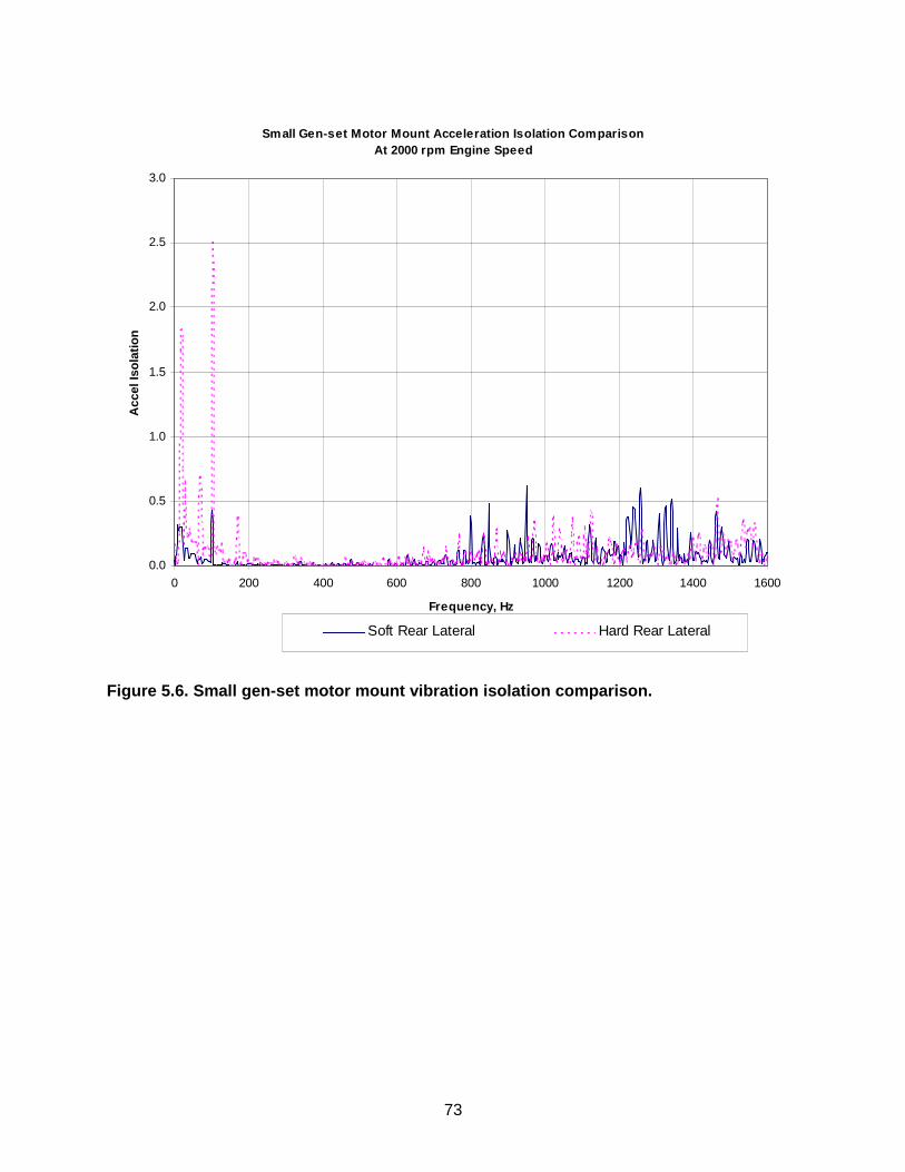
73
Small Gen-set Motor Mount Acceleration Isolation ComparisonAt 2000 rpm Engine Speed
0.0
0.5
1.0
1.5
2.0
2.5
3.0
0 200 400 600 800 1000 1200 1400 1600
Frequency, Hz
Acc
el Is
ola
tio
n
Soft Rear Lateral Hard Rear Lateral
Figure 5.6. Small gen-set motor mount vibration isolation comparison.

74
Small Variable Speed Diesel GeneratorAir Flow Rate vs Electric Power Output
100.0
150.0
200.0
250.0
300.0
350.0
400.0
450.0
500.0
0 1 2 3 4 5 6 7 8 9
Power, kW
Flo
w R
ate,
ft^
3/m
in
Total
Engine
Alt &Pow Elect
Ruggerini MD191 enginewith paper engine air intakeTEK 200 Alternator FanData 01-29-01
Figure 5.7. Small gen-set measured airflow versus load.

75
Small Variable Speed Diesel GeneratorAuto Control with 2400 rpm Min Speed Setting
2000
2200
2400
2600
2800
3000
3200
3400
3600
0 1 2 3 4 5 6 7 8 9 10
Elect Power Output, kW
Sp
eed
, rp
m
Figure 5.8. Small gen-set control speed versus load.

76
Small Variable Speed Diesel GeneratorInlet to Outlet Air Temperature Rise vs Electric Power Out
0
20
40
60
80
100
120
140
160
180
0 1 2 3 4 5 6 7 8 9 10
Electric Power Output, kW
Tem
p R
ise,
deg
F
Engine
Alt & Pow Elect
Data 09/21/01
Figure 5.9. Small gen-set inlet and outlet temperature rise versus load.

77
Figure 5.10. Large gen-set skid and housing. Alternator-end and throttle-side of the gen-set. Boxes for power electronics, computer, digital control, and display occupy the near end of the housing. Note the wire rope engine mounts. (P002920)

78
Figure 5.11. Large gen-set skid and housing. Alternator-end and silencer-side of the gen-set. Boxes for power electronics, computer, digital control, and display occupy the near end of the housing. (P002916)

79
Figure 5.12. Large gen-set skid and housing. Radiator-end and silencer-side of the gen-set. Boxes for power electronics, computer, digital control, and display occupy the far end of the housing. Part of the alternator can be seen at the rear (left end) of the engine. Note the wire rope engine mounts. (P002918)

80
Figure 5.13. Large gen-set skid and housing. Radiator-end and throttle-side of the gen-set. Boxes for power electronics, computer, digital control, and display occupy the far end of the housing. Part of the alternator can be seen at the rear (right end) of the engine. Note the wire rope engine mounts.

81
6. PERFORMANCE CHARACTERISTICS This chapter presents the operating characteristics and performance results from the small AMMPS proof-of-concept unit. Limited testing was conducted on the unit during the final assembly of the unit and once it was completed. The data were collected using standard industrial techniques (rather than Military Standards) and should be considered preliminary. The data, although preliminary, are useful in accessing the overall expected performance of the new gen-set units. Since much of the proof-of-concept design was done in parallel under a tight schedule, components were not adequately optimized to work together in the final gen-set. This chapter attempts to present the performance of the gen-set and provide areas where the results deviate from an optimum design. In areas where corrections are known, these are specified. In other words, the results described herein are from a non-optimized system. Given additional time, the existing unit can perform better; and moreover, new systems can also be expected to have improved performance. 6.1 Electrical Outputs The AMMPS proof-of-concept units were designed to produce full power at 120V, single phase, 240V “dual phase” (two 120V signals 180 degrees out of phase), and 208V three phase, all with unbalanced loads. Each voltage setting can be generated at an output frequency of 50, 60, or 400 Hz. Each of the nine potential settings (120V 1-phase, 240V 2-phase, 208V 3-phase, at 50, 60, and 400 Hz) has been realized with varying degrees of success. The 50 & 60 Hz frequencies work quite well. The quality of the 400 Hz output is marginal. We believe that with improved filters and increased processing speed, the 400 Hz waveform can be improved and made satisfactory. The 208V, three phase output also works quite well. The system was designed to be operated with unbalanced loads; however, during final testing it was determined that insufficient filters were built to handle much more than 1 kW of unbalanced load. Single phase loads (120V and 240V) are unaffected by this limitation. Unless specified otherwise, test results herein are 208V, three-phase, 60 Hz output. 6.2 System Rating Military generator sets are operated under extreme environmental conditions and are de-rated accordingly. The “nameplate” rating is the lowest rating from any of several tests but is generally determined by one of the following tests: • Full power at elevated temperatures (125F) • Full power at 4000 ft elevation and 95F ORNL developed a criterion for estimating the gen-set system rating from the manufacturer’s engine data operated at variable speed based on historical trends with military gen-set ratings and standard de-rating procedures. This criterion estimates that the gen-set nameplate rating is 65% of the engine power at 3000 rpm. Based on this criterion, the small gen-set based on the Ruggerini MD191 engine would be rated at 6-7 kW.

82
The small gen-set system was not tested under extreme environmental conditions to determine the actual “nameplate” data. However, the gen-set was tested at full load at standard conditions (70F, 900 ft elevation). Under these conditions, the gen-set was able to produce 10 kW for several minutes and functioned well at this power level. The maximum power output for the gen-set was 12 kW for a very limited time. Based on our experience, a typical non-military power rating for the gen-set set would be ~10 kW. As described in Chapter 3, the engine was run with both DF2 and JP8 and no power difference was found. Also as detailed in Chapter 3, the engine power decreases by 1.1 kW at the elevated temperature of 125F. Typically these conditions result in a 20% de-rating for engines. Since the gen-set power is limited by the engine power, it is a reasonable assumption that an appropriate and conservative military de-rating factor for the gen-set is 20%. Therefore, we estimate that the nameplate gen-set rating for this proof-of-concept would be ~8 kW. The criteria that we used to estimate the gen-set rating from the engine data may be slightly conservative but is a good estimation technique. The criterion was based on the engine power at 3000 rpm, and we were able to run the small proof-of-concept unit at speeds exceeding 3000 rpm resulting in the slight increase in output power. 6.3 Power Quality 6.3.1 Waveform The quality of the output power was found to be dependant on the stability and amplitude of the DC link. Originally the DC link was designed to vary between 350V and 450V. The minimum link voltage of 350V turned out to be insufficient to produce the waveform quality needed. During final assembly, the DC link voltage was modified to vary between 408V and 450V DC. This improved the output quality. However, in final testing we’ve learned that 408V DC may not have been the optimum setting to produce the best output waveform. Loads reduce the DC link more than anticipated, and at the higher loads, the output waveform suffers somewhat. The result is that at moderate to high loads, more DC link amplitude is needed than originally thought to produce a high quality 120V signal. Insufficient DC link amplitude results in the output signal being flattened at the peaks rather than sinusoidal. Figures 6.1 and 6.2 show output waveforms (60 Hz, three phase) at low (~1 kW) and high loads (~8kW). The waveform at 8 kW (Fig. 6.2) clearly shows the flattened peaks. The control system is designed to flatten the peaks if insufficient voltage exists on the DC link to maximize the power output. If the overall wave shape was kept to pure sinusoidal then less power could be delivered in these conditions. Since the DC link voltage could not be modified easily in the timeframe that we had to test the final assembled unit, we modified the output voltage setting from 120V to 115V. It was felt that power quality was more important than the additional 5V output. The output voltage is set in software and thus is simple to change. Output waveforms of the 115V signal are shown in Fig. 6.3 and 6.4, for ~1kW and ~8 kW respectively. The power quality is improved and the flatness of the output signal is reduced. 6.3.2 Total Harmonic Distortion (THD) THD measurements were made to quantify the output waveform quality. For the 120V three-phase output at 60 Hz, the THD for each phase as a function of output power is shown in Table 6.1. The average THD for the A, B, and C phases is 3.7%, 4.3%, and 3.0%, respectively. The differences in the output waveform quality among the three phases is due to slight differences in

83
the filters used. Fine tuning the filters can improve the THD further. The THD levels for the output waveforms at different loads for the 115V, three phase, 60 Hz signals are shown in Table 6.2. The average THD improves to 2.5%, 3.1%, and 2.0% for the A, B, and C phase, respectively. The drop in output voltage improves the THD as expected. Table 6.1 THD measurements for 120V, 60 Hz, three phase output at various loads levels
Total power (kW)
A phase THD (%)
B phase THD (%)
C Phase THD (%)
0.0003 2.0 1.9 2.3 1.391 2.3 3.2 1.5 2.473 2.9 3.8 2.2 3.524 3.6 4.4 3.0 4.556 4.2 5.0 3.2 5.147 4.3 5.1 3.4 6.193 4.6 5.4 3.8 7.230 4.5 5.3 3.6 8.365 4.6 5.0 3.5 9.631 4.0 3.9 3.0
Average 3.7 4.3 3.0 Table 6.2 THD measurements for 115V, 60 Hz, three phase output at various loads levels
Total power (kW)
A phase THD (%)
B phase THD (%)
C Phase THD (%)
0.0003 1.8 1.6 1.8 1.28 1.6 2.2 1.2 2.33 1.9 2.7 1.6 3.36 2.2 3.2 1.9 4.35 2.7 3.5 2.1 5.36 3.0 3.7 2.3 5.91 3.1 3.7 2.4 6.91 2.9 3.6 2.3 7.98 3.0 3.4 2.2
Average 2.5 3.1 2.0 6.3.3 Voltage Stability The stability of the output voltage is an important design feature of the proof-of-concept AMMPS gen-sets. The voltage of the proof-of-concepts is regulated in the digital control system. The voltage output of the proof-of-concept unit appears to be quite stable during normal operation. Voltages that were recorded during fuel consumption tests ranged between 117V and 121V. The voltage does not appear to drift as a function of increasing load. 6.3.4 Frequency Stability One of the advertised advantages of the power electronics/digital control design is the stability of the output frequency. This advantage seems to have been fully realized. The frequency simply does not vary as a function of load, speed or output. Frequency measurements were

84
taken during fuel consumption testing and were typically within 0.1% of the desired frequency. The maximum frequency deviation recorded from over 200 measurements was within 0.3%. Since frequency is determined by the DSP clock and the appropriate software it is possible to provide options that would allow frequency droop in certain situations. This would be very desirable in applications where the load was predominately a large induction motor. In this situation with the appropriate frequency droop, more power could be delivered to the motor on startup. This would accelerate the motor much more quickly and create less heating in it. 6.4 Transient Load Operation One of the most stringent tests of the generator set is the transient load test in which the gen-set has to quickly respond to a large load demand. The automatic load control scheme was set to allow the gen-set to have ample engine speed to handle the transient load effectively. The engine speed has been set at 200 rpm over the optimum speed for fuel efficiency (see discussion below) to handle transient loads. The value of 200 rpm was not optimized. Less speed increase could be used and be effective. To test the proof-of-concept unit for transients loads, the gen-set was operated at ~1 kW and then an 8 kW load was added. The control system steadily increases the engine speed to its set point in about 2-3 sec. No engine oscillation was noticed. The output voltage drops momentarily (to ~110V) until the battery boost can respond. Recall that the battery boost is still set to stabilize the DC link at 340V but the lower limit of the link is 408V. Once the battery boost “gap” is corrected, this voltage drop is expected to be negligible. During the transient, however, the frequency is totally unaffected. During small load transients (1-2kW), no drop in voltage was noticed and the engine responds in less than one second. 6.5 Optimum Variable Speed Operation The electric power output for the small diesel generator was estimated from the dynamometer measured engine performance map and assumed efficiencies of the permanent magnet alternator, the rectifier, and the inverter. The assumed electrical efficiencies are: alternator low power 80%; alternator high power 95%; rectifier 95%; inverter 93%; boost 90%; buck; 95%. Boost and buck efficiencies were not included in the analysis. Figure 6.5 shows a plot of electric output power versus speed, which includes the overall system thermal efficiency contours, and two estimated optimum variable-speed operating lines. Generally, the optimum variable speed-operating line is selected based upon maximizing thermal efficiency of the overall gen-set. A slight modification to this design criterion accommodates transient load conditions to prevent engine stall and DC link voltage sag. The transient-load optimum operating line is set at about 200 rpm faster than the estimated maximum efficiency line to allow sufficient excess engine torque capacity to accelerate to the desired operating speed under transient demand power increases. Also during transient load increases (demand engine acceleration), the digital control system off-loads the engine/alternator boost circuit and enables the battery boost of the DC link voltage momentarily while the engine accelerates to the requested speed. Both the 200-rpm speed margin and the transient battery boost help prevent engine stall and poor output power quality during transient demand power increases. Under load, the operating speed range for the Ruggerini MD191 diesel engine / small gen-set is selected between 2200 rpm (to prevent engine stall under transient load changes) and 3600

85
rpm (to avoid excess DC link voltage >500 volts limited by power electronic components). For power demands between zero and 4.8 kW, the small gen-set operates best at approximately 2200 rpm. For power demands from 4.8 to 9.7 kW the gen-set follows the linearized transient-load optimum operating line from 2200 to 3600 rpm where the system efficiency is near maximum. Under no-load, the engine can idle between 1800 and 2000 rpm. A plot of the small gen-set thermal efficiency versus electric load is shown in Figure 6.6. Estimated system thermal efficiencies for fixed-speed and variable-speed operation are shown. The variable speed operation line is an attempt to run the system on the maximum efficiency envelope of all the fixed speed contours shown in Figure 6.6. Two estimated variable speed operating lines are shown. One is the estimated variable speed operating line for maximum efficiency. The other is the estimated optimum operating line with the modified speed margin to accommodate transient load conditions. Shown also in Figure 6.6 is the efficiency versus output power measured on the small gen-set when operated with the automatic (transient-load) variable speed control line in the digital control system. The gen-set system thermal efficiency ranged from 13% at 1.4 kW to a maximum of 26% at 6.2 kW. The system efficiency remains relatively flat at ~24% from 4 kW to 9.6 kW. The measured gen-set efficiency data agree very well with the estimated transient-load control line efficiency. The estimated efficiencies are from engine dynamometer performance map tests and the assumed electrical efficiencies above. For loads up to 5 kW, agreement between measured and estimated thermal efficiency is very close. For loads greater than 6 kW the measured thermal efficiency is 1 to 3 percentage points greater than estimated. The relatively close agreement tends to substantiate the alternator and power electronics efficiencies used. In Figure 6.6, the measured variable speed thermal efficiency below 4.5 kW is lower than the estimated efficiency at 2000 rpm fixed speed. If the estimated thermal efficiencies at 2000 rpm at loads below 4 kW are correct, some low load thermal efficiencies may have been sacrificed to accommodate transient load increases. This would be the result of not permitting the loaded speed to drop below 2200 rpm under variable speed control. A more conclusive statement about this issue could be made if there were measured gen-set system efficiency data at 2000 rpm fixed speed. 6.6 Measured System Efficiency Fuel consumption measurements were made on the proof-of-concept unit to determine the overall system efficiency. The measurements were made at various output power levels to determine partial load and full load efficiency. The measurements were taken using typical DF-2 as a fuel (energy content 83.7 g/kW-hr) under three phase, 208V output power. Measurements were made under increasing load and then also with decreasing load to determine if there was any difference in fuel consumption with load rate. Fuel consumption data was also taken at 240V, double phase and 120V single phase to see if the output power signal has a significant effect on fuel consumption. All fuel consumption data were taken after the system had been allowed to warm up. During the final assembly testing, it was determined that the system efficiency is reduced significantly before it warms up. Fuel consumption data shows that the efficiency for the system was barely over 20% while cool but increased to ~25% and leveled out after approximately 30-45 minutes of warm up.

86
The resulting fuel consumption data are shown in Fig. 6.7. There are several observations that can be drawn from these data. • The system operates from ~4.5 to 9.5 kW and beyond at its peak efficiency of 25 to 26%.
This large high efficiency plateau range is helpful in reducing the overall fuel consumption in military systems since these systems are often used at partial load.
• All three output power conditions tested had consistent efficiencies once normalized for output power. The efficiency with increasing and decreasing power was not appreciably different.
• The system efficiency was measured under increasing load at ~1kW increments and at decreasing load at ~2kW increments with no real difference in system efficiency.
It should be noted that the system efficiency was not optimized for the proof-of-concept unit. While dramatic increases in system efficiency are not likely, some improvements in system efficiency would be possible. Better engine control during transient operation could bring about additional efficiency improvements. 6.6.1 Lessons Learned on System Optimization The lessons learned regarding the optimization of the system are summarized here. The fuller explanation is in the previous section. • The optimum operating line can be a simple speed-load relationship base on the engine and
gen-set overall performance map. A complicated look-up table in the digital control system is not needed.
• To handle load transients without stalling the engine or reducing the transient power quality,
the optimum operating line may have to trade off some thermal efficiency to allow for excess torque capacity needed for engine acceleration.
• Using the battery for temporary output-power fill-in during transient load increases has been
demonstrated using the variable speed power electronics and digital control. • Variable speed control can flatten the thermal efficiency over a wider load range. • It has been demonstrated that variable-speed controlled gen-sets are more efficient than
fixed speed gen-sets especially at partial loads, which is where the gen-sets are operated most of the time.
• Check the engine and alternator torque compatibility for smooth, stall-free engine
acceleration during transient load increases especially under the alternator boost operating mode.
• Temporary battery boost of the DC link instead of alternator boost of the DC link was
successfully used to help off-load the engine so that it can accelerate to the optimum speed under transient load increases.

87
6.7 Variable Speed Control One of the primary design aspects of the proposed AMMPS design is the operation under variable speed control, which was successfully demonstrated in the proof-of-concept unit. Figure 6.8 shows the engine speed as a function of output power. The system is designed to operate at about 2200 rpm at loads of 4 kW or less. Beyond 4 kW, the engine speed increases linearly with power until it reaches 3600 rpm at ~10kW. Engine control appears to be stable with both increasing and decreasing power changes. It is interesting to note that, compared to fixed speed, allowing the engine to operate at variable speed increases the gen-set power output from about 4 kW to greater than 8 kW. This highlights that one of the primary advantages of variable speed control is the decreased weight of the system due to the increased engine speeds. To compare the efficiency improvements associated with variable speed control, the system efficiency of the variable-speed proof-of-concept unit and a fixed-speed 10 kW TQG were measured. Fuel consumption data was converted to system efficiency and then normalized by the maximum efficiency for that system. For the 10 kW TQG, the maximum efficiency was 26.8%; for the proof-of-concept unit, the maximum efficiency was 26.2%. The normalized efficiency data are plotted against normalized load. The loads are normalized by the nameplate rating of 10 kW for the TQG and 8 kW for the AMMPS unit. Figure 6.9 shows the efficiency comparison of the TQG and AMMPS units normalized as described to compare the efficiency of the fixed speed and variable speed control. Please note that the accuracy of the data for the TQG is not as reliable as that for the AMMPS unit but the general shape of the curve shows the expected trend. Figure 6.9 indicates that the notable difference is that the partial load efficiency is greater in the AMMPS unit than the TQG. This difference is significant since military units are most often used at partial load. At 25% and 50% rated, the variable speed control appears to increase the efficiency about 10%. These measured fuel consumption results are comparable to similar results of an earlier analysis, which compares fuel consumption of variable speed operation with that of fixed speed operation. The results are summarized in Table 6.3. Table 6.3 Fuel saved due to variable-speed control relative to fixed-speed control
Utilization Profile Wartime 30-Day Mission
Wartime 15-Day Mission
Peace Time
Generator Rated Power
Over 60 kW 60 kW & Under 5kW Through 60 kW
Avg. Demand Power % Of Rated
69.9% 58.1% 27.8%
Avg. Operating Time Hrs / Mo
686 340 23.2
Fixed Operating Speed
Fuel Savings
1800 rpm 1.3% 2.6% 12.0% 3000 rpm 7.3% 10.5% 29.6% 3600 rpm 14.6% 18.8% 36%
These results show that variable speed control provides the most fuel savings when the gen-set is operated well short of its rated load capacity typical of peacetime operation. Fuel savings from variable speed is less when the gen-set is operated closer to rated capacity typical of wartime

88
missions. Compared to 1800 rpm fixed speed, variable-speed control saves about 12% fuel at 28% of rated load. These computer simulation results are comparable to the measured 10 % AMMPS savings versus TQG (1800 rpm) results reported above. Using measured engine efficiency maps, the computer model determines the most efficient operating speed for each demand power level and compares it to the efficiency as if the same engine were controlled at a selected constant speed. Details of the Advanced Generator Evaluation Tool (AGET) computer model is described in Andriulli et al. (1999). The model was developed by Dr. Pedro Otaduy of ORNL. It seems useful to summarize the advantages and disadvantages of variable speed engine control based on the proof-of-concept unit with the two most likely alternatives, fixed speed at 1800 and 3600 rpm. Advantages/Disadvantages of 1800 rpm operation: • Select number of well characterized engines tuned to one speed • Simpler electronics • Heaviest system weights • Wetstacking problems prevail • Less stable waveform output (varies with engine speed) Advantages/Disadvantages of 3600 rpm operation: • Fewer engines to choose from • Decreased engine life • Increased noise • Decreased fuel consumption • Increased possibility of wetstacking • Smaller, lighter engine • Simpler electronics • Less stable waveform output (varies with engine speed) Advantages/Disadvantages of variable speed operation: • Wider selection of engine choices since it does not have to be tuned to a specific speed • Improved fuel efficiency • Decreased chances of wetstacking • Smaller, lighter engine and system • More complex electronics • More stable waveform output (independent of load) • More flexible system (multiple frequencies) The use of variable speed engine operation is more complex but the numerous advantages would outweigh the disadvantages once confidence is gained in the use of this type of system. 6.8 Weight and Volume The final weight of the small AMMPS proof-of-concept unit is approximately 524 lb dry and 576 lbs wet with engine oil and 8 gallons of fuel. The delivered system contains a standard 28-volt battery-charging alternator, regulator and brackets weighing 5.4 lbs that are not necessary and not used. Without the extra alternator, the dry and wet weights would be 519 lbs and 571 lbs respectively. This compares favorably with a design weight of 550 lb. and a military target

89
weight of 500 lb. The nameplate rating of the gen-set is estimated at 8 kW, which improves the power-to-weight ratio of the system. The weight budget of key components in the overall system is shown in Table 6.4. Therefore the overall system weight is considered fairly representative. Additional weight savings could be realized through the use of composite materials – which were not included in this system due to the prohibitive cost and schedule. In addition, the system can be re-designed to use a lighter fuel tank or integrate the fuel tank in the gen-set skid. An additional opportunity for weight savings that was not attempted in this phase is the use of an ORNL-developed thermal foam, which can be used as an effective heat sink for the electronics. It is estimated that this material could effectively replace the aluminum heat sink saving ~15 lb. The final dimensions of the small proof-of-concept unit are 31.3 in. x 30.1 in x 49.0 in, for a volume of ~29 cubic ft. As has been discussed, the volume is more difficult to reduce than the weight. One of the primary design tradeoffs is between volume, airflow (for cooling), and acoustics. In our opinion, the current volume is somewhat undersized. Slightly more gen-set volume would increase the cooling capability and allow for better noise baffling and acoustical treatment. A relatively small volume increase can provide significant improvements in both the acoustical signature and cooling capability of the system. Table 6.4 Estimated weight budget for 8-kW AMMPS proof-of-concept unit 8-kW gen-set components Estimated weight (lb) diesel engine with air-cooling fan, ring gear, oil & fuel filter 123 starter motor 10 air intake & filter 3 engine exhaust manifold 3 scroll muffler, insulation, pipe, brackets 20 engine mounts and brackets 5 stator - radial gap PM alternator 24 rotor - radial gap PM alternator 13 power electronics 20 fan & intake duct for alternator 3 enclosure box for power electronics 9 fuel tank 8 fuel lines, filler neck, level gage, etc. 5 8 hours of fuel 35 engine lubrication oil 4
batteries (2), battery cables 40 controls/diagnostics (computer, gages, switches, instruments)
45
load terminals, receptacles, ground rods 10 Internals subtotal 380
aluminum skid 63 frame & enclosure with thermal and sound management materials
90
Housing subtotal 153
Total (lbs) 533

90
6.9 System Lessons Learned Several of the lessons learned were broad-based and somewhat related to the design philosophy rather than specific components in our proof-of-concept unit. However, we at ORNL feel quite strongly that these lessons learned are very important for this and future AMMPS programs. Previously the engine was treated as the critical component to a new gen-set and for good reason. The engine was the prime mover for the system and proper control of the engine was responsible for the power quality (or at least the output frequency). In the AMMPS proof-of-concept unit, the critical component is not the engine; however, it is the power electronics. The power electronics provides the output power and operates almost independently of the prime mover. The power electronics is responsible for the power quality and output condition. The power electronics (coupled with adequate controls) allows for new options that have never been possible before. Some of these options were attempted in the proof-of-concept unit, such as: • Wider choice of engines to use because engines don’t have to be optimized at 1800 rpm • Multiple frequencies available from a single unit • High power quality with no variation in output frequency and minimal variation in voltage with
change in load • Variable speed engine control which can reduce weight, reduce wetstacking, and save fuel • Operate multiple phases with fully unbalanced loads • Improve transient load response by augmenting engine-generator output power with battery
power In addition, several options are available but were not attempted in this unit: • DC charging station to replace engine-based battery charging units • Self correcting power output that adjusts power factor to key loads to aid start-up (quicker
start-up of motors) • Proper coupling of energy storage to allow for more refined power management • Parallel operation of multiple generator sets • Inclusion of multiple control schemes to optimize control for various conditions (optimum
efficiency, minimize noise, etc.) The bottom line is that the power electronics modules are extremely flexible and can provide substantial military benefits. However, as was learned vividly in this project, proper power electronics design is not simple or quick. There are multiple difficulties associated with the use of power electronics that must be carefully considered against alternatives. Some of the obstacles that need to be addressed in any successful power electronics design are: • Need for high reliability components and system • Thermal management (clearly related to reliability) in high temperature applications • Electrical noise (EMI) control • Lack of broad military experience base • Modified maintenance and repair procedures (this could be better, actually) • Cost and schedule Weighing all of the obstacles and all of the opportunities available with power electronics, we feel that this technology is very viable but it is not trivial, and the success the power electronics design will largely determine the success of any system based on it. In other words, a lesson learned is that the key component in the AMMPS proof-of-concept unit is not the engine but the power electronics.

91
As important as any component is, the overall system performance will be determined more through system design than through the optimization of a single component. ORNL developed a healthy respect for the complexity of generator sets in the military setting and the design decisions that must be made to get these units to operate effectively. Simply put, a collection of optimized components will not result in an optimized system. The initial proof-of-concept unit was designed more on the component level rather than the system level and the resulting system is not optimized. The generator set design is a series of trade-offs that must be managed and designed appropriately. Specific trade-offs encountered in the proof-of-concept phase include: • Thermal management (affects noise and volume) • Use of alternator boost circuit (affects variable speed operation and reliability) • Extent of variable speed (affects efficiency, wetstacking, and engine/alternator selection) Therefore, we must stress that design and optimization of the generator set system must come from the system level not from the component level. The experience base for the components and system approach in the proof-of-concept design is simply not as great as with conventional generator set design. Therefore, fabrication that can be taken in parallel using conventional components should be done in sequence. In particular the power electronics design simply needs more time than was allocated to work out all of the bugs. More time was needed to integrate and check out the combined power electronics and digital control systems. Even in light of the rapid growth in the power electronics field, we have learned that the experience base is insufficient to allow for parallel design and fabrication of key components.

92
Fig. 6.1. Output waveform for 120V, three phase (line-to-line in blue), 60 Hz output at ~1kW.
Fig. 6.2. Output waveform for 120V, three phase (line-to-line in blue), 60 Hz output at ~8kW.

93
Fig. 6.3. Output waveform for 115V, three phase (line-to-line/2 in blue), 60 Hz output at ~1kW.
Fig. 6.4. Output waveform for 115V, three phase (line-to-line/2 in blue), 60 Hz output at ~8kW.

94
Small Gen-Set Estimated Electric Power OutputWith Overall Thermal Efficiency Contours & Operating Lin
0
2
4
6
8
10
12
2000 2200 2400 2600 2800 3000 3200 3400 3600
Speed, rpm
22%
22%24%
24%
20%
15%
10%
Max EffiencyLine
25.5%
Max Power
Operating line, Transient Load eqn: rpm = 900 + 270.3 x kWMinimum Loaded Speed = 2200 rpmDC link voltage = 500V @ max speed = 3600 rpmMin alternator DC link boost set point = 408 VDC (no load) at speed < 2940 r
Operating LineTransient Load
Fig. 6.5. Estimated efficiency map of the small proof-of-concept gen-set system.

95
Fig. 6.6. Estimated and actual efficiency as a function of load and speed.
Small Gen-Set Thermal Efficiency vs Electric Power OutpFixed Speed & Optimum Variable Speed Operation
0.0%
5.0%
10.0%
15.0%
20.0%
25.0%
30.0%
0 2 4 6 8 10
Electric Power Output, kW
Est Var Spd Max Eff Oper Line
Est Var Spd Trans Load Oper Line
Measured Eff for Var Spd Trans Load Op Line
Est Eff at Fixed 2000 rpm
Est Eff at Fixed 2400 rpm
Est Eff at Fixed 3000 rpm
Est Eff at Fixed 3600 rpm

96
Fig. 6.7. Measured system efficiency for small AMMPS proof-of-concept unit.
System Efficiency Data
0.0%
5.0%
10.0%
15.0%
20.0%
25.0%
30.0%
0 1 2 3 4 5 6 7 8 9 10
Electrical Power (kW)
Increasing Power; 208V, 3PhaseDecreasing Power; 208V, 3Phase240V, 2 Phase
120V, 1 Phase

97
Fig 6.8. Engine speed as a function of output power showing variable speed operation.
Automatic Control of Gen-Set
0
500
1000
1500
2000
2500
3000
3500
4000
0 2 4 6 8 10 12
Electrical Power (kW)
Speed

98
Fig. 6.9. Normalized efficiency vs. normalized load comparing fixed and variable speed control.
Comparison of Fixed vs. Variable Speed Control
0.0%
20.0%
40.0%
60.0%
80.0%
100.0%
120.0%
0% 20% 40% 60% 80% 100% 120% 140%
Normalized Load (%)
10 kW TQG Data
8 kW AMMPS Data
99
7. SUMMARY OF LESSONS LEARNED AND FUTURE SPECIFICATIONS This chapter summarizes the proof-of-concept phase of the AMMPS project at ORNL. Lessons learned throughout the project are included in appropriate sections of this report and are summarized here. Based on experience thus far with the proof-of-concept gen-set, recommendations are made for writing achievable specifications for the production AMMPS units. Distinction is made between performance that was demonstrated and performance that can be reasonably anticipated. 7.1 Summary of lessons Learned The lessons that have been learned during the proof-of-concept phase are described in the preceding chapters but are summarized here out explanation. The summary does include the section in which the lesson originally was described. 7.1.1 Engine Lessons Learned (Section 3.1.6) • Original Equipment Manufacturer (OEM) technical support is absolutely necessary when
converting an automotive engine to an industrial application. • The new injection technology available in today’s automotive engines can provide significant
military benefits that merit full consideration. 7.1.2 Alternator Lessons Learned (Section 3.2.4) • Matching the engine and alternator power curves is a good first-cut design approach.
Eventually, however, the engine speed and required voltage and the engine torque and the required current will have to be matched.
• It is important to have reliable engine performance data under prototypical conditions before
specifying the alternator design since the two must match. • There is little weight penalty if any for having to over-design the alternator for power curve
shape mismatch between the engine and alternator. • The mechanical interface between the engine and alternator is more important to the PM
alternator design than the specific type of PM alternator used (radial gap v. axial gap) 7.1.3 Lessons Learned from Power Electronics and Digital Controls (Section 4.4) • Power electronics and the control system must be completely integrated in order for this
system to function. In our opinion, these systems need to be developed in parallel with each other in close proximity with each other. Close coordination and constant exchange between the two is essential to insure efficient, effective, robust, and timely design. There is a lot that has to be coordinated and having one part designed at a different location generates too many errors due to poor coordination.
• Reliability of PE is a concern and must be built in from the outset. Issues such as proper
thermal management, vibration control, protection from elements need to be considered in

100
the overall system design. We advocate the use of a modular design and sufficient separation between components to facilitate thermal management and ease of repair. Moreover, the power electronics design itself needs to factor in reliability issues.
• Electrical noise and interference are prevalent everywhere. Proper and redundant noise
suppression is required. • Alternator boost circuit improves flexibility and increases the speed range of the alternator
and thus the system but the long-term reliability of the system is not verified. Alternative PE topologies may be used to avoid this feature.
• Need multiple tuned filters for 50/60 & 400 Hz. This will increase the system weight but noise
suppression is vitally important to the proper operation of the system. • Noise on DC link ruins system. • While floating point DSPs are expensive compared to integer DSPs, the development time
for integer DSPs is considerably higher. Weighing the cost of development vs. hardware costs, there would have to be a very large production volume to warrant the extra development effort for integer DSP use.
• The inverter needs to be designed in such a way that any signal from the controller cannot
create a conflict or an over-current situation. This will prevent spurious signals or loss of control from causing any damage to the system. For example logic needs to be designed such that the same top and bottom leg of an output cannot be active at the same time and in addition have the dead-time built into hardware, even though the control signals may call for it.
• All sensors need to be isolated to prevent false offsets. • All digital logic needs to be level rather than edge triggered for noise immunity. In addition
the level trigger may need to be extended and highly filtered to prevent false triggering. • All analog inputs need to be differential to reduce noise from the inverter. • All power cables need to be well shielded, twisted, and kept short to reduce noise emission.
The boost circuit used to increase the permanent magnet generator voltage output at a given engine speed used the inductance of the generator as part of the circuit. This meant that switching noise is being generated in the power leads to the generator and must be well shielded.
• Analog sampling of the output voltage and current, need to be synchronized with the PWM
generator. The effect of the small ripple produced on the output can be eliminated with this approach.
• The TMS320F6701 computer processor is capable of running the 160,000 interrupts per
second to generate the PWM signals for all six IGBTs and A/D sampling. This uses about one third of its processing capability, leaving the remaining two thirds for the executive. It would be most desirable to generate the PWM signal in hardware for robustness. This would

also allow a faster response for the executive to calculate corrections to the output waveform and would provide a better output waveform quality.
• The reaction of the output magnetics at startup required the control system to start the PWM
frequency at 50 KHz and ramp it down to the operating 20 KHz frequency. Otherwise a resonance in the magnetics was excited causing an over-current shutdown in the inverter. This startup ramp would be very difficult to do with the conventional analog version PWM from a triangle wave generator, but was easily performed with the digital system.
• The inverter has four current sensors on the output lines (A,B,C & Neutral phases) for over
current protection. Since they are located before the output filter they will include the currents which go into the filter capacitors and not the output load. This interferes with measuring the load currents and power factors. In principle this can be calculated out of current measurements but it is not an easy nor accurate task. If accurate current and power factor measurements of the load are desired then it would be best to include current sensors on the output terminals of the gen-set.
• Surges on the battery such as starting the engine can cause momentary dips in the power to
the computer and the other low voltage components. This can lead to outages in the computer causing it to reboot and start the process all over again. Therefore the computer power supply may require some kind of uninterruptible power supply (UPS) for these occasions. Since these outages are usually less than several seconds, the UPS does not have to provide much energy and can be accomplished with some large capacitors. Dropouts on our system last for about 30ms for computer turn on and about 100ms for engine start.
• Use of a standard operating system (OS) like Windows, requires the power management to
last long enough to an allow orderly shutdown of the system (for the OS to go through it's standard shutdown procedure) and prevent disk write errors.
• Protection needs to be provided for shorted outputs. If an output is shorted then the PWM
control signal to the shorted phase becomes a voltage boost to the generator. In this case the voltage generated on the link can exceed safe limits and possibly blow the IGBTs and other components as well.
• For electrical noise immunity of the generator boost circuit, it may be best to enclose the
rectifier/boost circuit as part of the generator and just run the 3-wire (plus, minus, & neutral) DC power out of it to the link.
During the course of this phase, ORNL altered the process of cooling the electronics. We originally had mounted the electronics in boxes attached directly to the engine shaft beyond the alternator. This was done to provide as much cooling air as possible. We altered our approach and moved to a passive system where the electronics were not directly cooled with the air but heat sinks were used and the cooling air removed heat from the sinks. This was done to reduce the vibration and contamination of the electronics. We feel this is still the proper step and in fact, now advocate the use of a modular design of all systems in the gen-set. More attention will be given to this issue in following sections of the report.
•
•
The neutral line was a continuous connection between the common on the generator windings through the system to the earth ground. This was intended to reference the entire
101

system to earth ground and make for a simpler and safer system. However, since the link was only regulated between the plus and minus rails, there was no control on where the neutral voltage ended up in relation to the plus and minus rail voltages. Future designs can correct this problem by using two voltage regulation circuits instead of the one used in this design—one for the plus rail to neutral and one for the minus rail to neutral—and regulating them independently. This would simplify the control and allow full voltage output swings with less rail-to-rail voltage. An alternate approach is to generate this neutral reference with a fourth inverter leg and do away with the neutral line from the generator. This approach would not provide a continuous connection back to the generator but might be simpler to design in some applications.
7.1.4 Systems Integration Lessons Learned (Sections 5.1.3, 5.2.1, 5.3.5, and 5.4.4)
An improved redesign of the small gen-set would be to make it bigger in volume. It is simply too small now to accommodate all components and functions required. This is quite obvious when one looks in the housing.
•
•
•
•
•
•
•
•
•
•
In future production gen-sets, there will be some improvement in the volume crunch by the reduction in some production components like the computer. But there are other components (such as filter magnetics), airflow needs, and acoustic baffling that will not allow any further reduction in volume.
Cooling air design approach is different for air-cooled and water-cooled engines.
The housing needs to be partitioned into heat-sensitive and heat insensitive compartments. A larger housing would greatly simplify the hot/cool partitioning.
Supply cool air from outside the gen-set directly to all the areas requiring cooling. Direct hot air away from sensitive components.
Avoid dead air or re-circulation spots where hot air can accumulate in the housing.
In the initial small gen-set configuration, there was an attempt to use baffling to collect and channel hot air outside the housing before it could get to heat sensitive parts. This was not successful mainly because of difficulty in sealing around the soft mounted engine and alternator and because of lack of sufficient volume in the housing
Modularize electrical subassemblies in boxes for cleanliness, EMI shielding, and simplified maintenance and repair. Ease of access to key components is important for repair. External casing sides should be hinged on the bottom in key areas where access is needed. This would allow the side to fold down providing easy access without having to undo too many screws.
Aluminum is a good material for limited volume production. Composites may be attractive for large production runs.
The noise signature from small engines can be reduced with standard noise abatement techniques, but it is not a trivial task.
102

Small (fewer cylinder) engines can be noisier and can have more vibration than larger multi-cylinder engines. Pay attention to the firing sequence of the 2 cylinder engines. Engines with even firing sequences will be quieter and have less vibration than engines with an uneven firing sequence.
•
•
•
•
•
•
•
•
•
•
•
•
•
Low noise silencers must be large in volume for better attenuation. They must have large inlet and outlet to keep exhaust gas velocities low for reduced noise and low exhaust back-pressure for greater engine efficiency.
Greater volume silencers mean greater weight but the increased silencer weight is more than offset by decreased engine weight.
Acoustic insulation on all exterior surfaces occupies significant volume in the gen-set housing. It also adds to the weight. However, the acoustic insulation is effective at reducing the noise levels.
The engine, alternator, and other hardware mount selection is a compromise between being soft enough to isolate vibration and stiff enough to attenuate shock loads without excessive displacement.
Wire rope mounts dampen comparably to rubber mounts and are a reasonable replacement for rubber mounts to reduce the possibility of material deterioration experienced in the past.
Wire rope mounts may tend to have a spring rate that softens with displacement in some load directions. This could make the selection compromise between vibration isolation and shock loading more difficult compared to other mounts (like some rubber mount configurations) that have spring rates that harden with displacement.
Different compound selection may be an alternative to improve rubber mount life.
7.1.5 Lessons Learned on System Optimization
The optimum operating line can be a simple speed-load relationship base on the engine and gen-set overall performance map. A complicated look-up table in the digital control system was not needed for this engine.
To handle load transients without stalling the engine or reducing the transient power quality, the optimum operating line may have to trade off some thermal efficiency to allow for excess torque capacity needed for engine acceleration.
Using the battery for temporary output-power fill-in during transient load increases has been demonstrated using the variable speed power electronics and digital control.
Variable speed control can maintain good thermal efficiency over a wider load range.
It has been demonstrated that variable-speed controlled gen-sets are more efficient than fixed speed gen-sets especially at partial loads, which is where the gen-sets are operated most of the time.
103

Check the engine and alternator torque compatibility for smooth, stall-free engine acceleration during transient load increases especially under the alternator boost operating mode.
•
•
•
•
•
Temporary battery boost of the DC link instead of alternator boost of the DC link was successfully used to help off-load the engine so that it can accelerate to the optimum speed under transient load increases.
The key component in the AMMPS proof-of-concept unit is not the engine but the power electronics. The design and optimization of the generator set system must come from the system level not from the component level.
The experience base for many components in the gen-set is insufficient to allow for parallel design and fabrication of key components. This means that following system design, some components will have to be fabricated sequentially rather than all in parallel.
7.2 Recommendations for Future Specifications Based on our experience with the proof-of-concept unit, we offer the following recommendations for reasonable expectations for future AMMPS units. 7.2.1 Family Sizes and Modes A couple of key decisions must be made by the military about the number of families and the sizes specified in the AMMPS production units. In the authors’ opinion, the military should first decide the specific family sizes requested. Previously, gen-sets were built to specific sizes (5, 10, 15, 30, and 60 kW). If these sizes need to be exactly replaced, then the weight of the gen-set families could increase. We found that there was not a continuum of lightweight engines from which to build these gen-sets. In other words, designing to arbitrary sizes rather than sizing everything to the engine, may result in a weight penalty if there does not happen to be a quality lightweight engine for that size. Our initial recommendation was that the three family sizes (7, 22, & 60 kW) would be sufficient to cover the entire medium range (5-60 kW). Based on our experience in the proof-of-concept phase, three sizes as described would be the minimum number for AMMPS. The optimum number - appears to be either 3 or 4 - would depend on several factors that must be weighed by the military. Three units would be less logistical burden but four sizes would provide an opportunity to more closely match the required demand with the generator capacity (less mismatch between what is needed and what is taken to the field). Based on the results of the proof-of-concept unit, it appears feasible to expect that multiple frequency modes (50, 60, & 400 Hz) could be consolidated into a single unit. Although the 400 Hz output of the existing unit is not yet of acceptable quality, the steps necessary to improve the 400 Hz signal are known. 7.2.2 Gen-Set Weight and Volume The estimated weight and volume for the future medium sized gen-sets are based upon evaluating and comparing the parameters of specific weight and specific volume (weight per unit
104

rated power, lb/kW and volume per unit rated power, ft^3/kW). The specific weight and volume of the proof-of-concept AMMPS gen-sets, which were analyzed and developed in this program, are compared to the baseline TQG gen-sets. General trend lines for the specific weight and specific volume for the AMMPS prototype, AMMPS future production gen-sets and the medium range TQG gen-sets are shown in Figures 7.1 and 7.2 respectively. The proof-of-concept AMMPS gen-sets, in this program, average about 55% lower in specific weight and 40% lower in specific volume than the baseline TQG gen-sets in the medium 5 through 60 kW range. However, a portion of these significant weight and volume reductions were achieved by trading off some of the performance goals in electrical quality, heat rejection, and acoustics. To improve the expected performance, we anticipate that the future production AMMPS will need to be about 10% larger in weight and 20% larger in volume than the prototype AMMPS. As explained elsewhere in this report, the added volume and weight is needed because of the need for additional electrical output filters, for more cooling airflow, and for more acoustic baffling and insulation. Weight and Volume Recommendation A reasonable target to specify for the production AMMPS gen-set is for about a 50% reduction in specific weight and about a 28% reduction in specific volume compared to the baseline TQG. This specification guidance applies generally across the full medium gen-set range from 5 to 60 kW. Specific gen-set weight and size adjustment may vary somewhat from these general guidelines. 7.2.3 Fuel Consumption Fuel consumption in the future production AMMPS gen-set can be lower than TQG gen-sets by two means. One is due to the new automotive-developed common-rail electronic fuel injection systems, which is expected to be transferred to industrial engines in the coming years. The other means is due to automatic variable-speed gen-set control instead of fixed-speed control. The specification preparation should take advantage of any reasonable improvements in fuel consumption foreseen in newly developed diesel fueling systems whether the gen-sets are fixed-speed or variable-speed designs. These new fueling systems are anticipated to reduce fuel consumption 5% to10% especially when applied to widely varying load conditions (or even if at fixed speed operation). A reduction in fuel consumption of this magnitude was demonstrated on the Hatz engine at UTK with the high-pressure common rail system (Ferguson 2001). In this report, variable-speed control gen-set system design is shown to be more fuel-efficient than the fixed-speed TQG design. Comparison fuel consumption tests were conducted on the variable speed small 8 kW AMMPS gen-set and a fixed-speed 10 kW TQG gen-set. The data were normalized to both maximum efficiency and rated load for each gen-set to eliminate bias in the comparison. At rated load, there is no significant difference in thermal efficiency because both systems are designed for maximum efficiency at the load condition. The variable-speed design maintains higher efficiency over a wider load range than does the fixed-speed design. The variable-speed has advantage at partial load where gen-sets operate most of the time. For example, at 50% load, the variable-speed AMMPS is about 10% more efficient than the fixed-speed TQG.
105

Earlier studies with the gen-set simulator program, show that when gen-sets are operated in peacetime mission profiles at partial load, the variable-speed operation gives about a 12% reduction in fuel consumption compared to fixed-speed engine operation at 1800 rpm. The simulation showed that variable-speed operation would reduce fuel consumption in typical peacetime missions up to 36% when compared to fixed-speed engine operation at 3600 rpm. Fuel Consumption Recommendation If fuel consumption is an important mission issue, we recommend writing the specification in such a way as to take full advantage of variable-speed operation. If fuel consumption is not an important issue, then variable speed control may not be necessary unless one wants to take advantage of other variable-speed benefits. 7.2.4 Acoustics The AMMPS program has a goal of reducing the gen-set acoustic noise at 7 meters by 5 dBA to 65 dBA. This was not demonstrated with the proof-of-concept gen-set because the Ruggerini engine is very noisy and because the prototype housing is too small. The housing reduced the engine noise significantly but not enough to meet the goal at full power. The noisiest direction of the small gen-set is at the engine cooling air inlet. While this airflow passage is somewhat indirect, it is clear that more acoustic baffling and insulation is needed in this area. Acoustic Recommendation The best approach to further reduce the noise is to increase the housing volume. A larger volume will permit more serpentine baffling and increased acoustic insulation while allowing greater cooling airflow. As discussed in the section on Weight and Volume, a specific volume reduction of 28% relative to the TQG is a reasonable start for the next iteration or production housing design. Assuming the prototype volume can be increased as recommended, then it would be reasonable to expect to meet the existing acoustical limit of 65 dBA at 7 meters. 7.2.5 Power Quality Power quality is becoming increasingly important in military systems. Based on our experience with the proof-of-concept units, the power quality need not be compromised with the use of power electronics-based power systems. Waveform Distortion It is reasonable to expect that the total harmonic distortion (THD), transient response, and other measures of power quality would be equal to or better than TQG levels. Unfortunately, we are not able to quantify the extent of the improvement at this time. Waveform Stability (voltage and frequency) The stability of the output waveform is one of the inherent advantages of the recommended design. Both voltage and frequency stability was demonstrated during the proof-of-concept phase. Voltage stability within 2% should be viable; frequency variation <<1% should be expected. Solid performance during transient loads was also demonstrated. A reasonable expectation is that the full transient load can be handled as well or better than in the TQGs. 7.2.6 Low Power Factor Loads Low power factors are an area where the recommended system can greatly exceed existing systems. A reasonable expectation is that the gen-set can handle power factors of 0.5 or
106

perhaps even less. This suggestion is made based on our understanding of the design in the proof-of-concept unit and has not been verified in practice. But good low power factor performance is reasonable to expect. 7.2.7 Unbalanced Loads One of the advantages of the recommended system is that unbalanced loads can be more easily handled. Our design was for a fully unbalanced load. However, this design advantage was not realized due to insufficient filters in the system. Once that deficiency is corrected, we would expect that this advantage could be realized. Therefore, since this benefit is not confirmed, a reasonable expectation would be to specify a design for 50% unbalanced load. Since each phase is regulated completely independently of the others, load imbalance in the various phases should not affect their regulation if the output filter is designed to handle this. 7.2.8 Parallel Operation Although the parallel operation cannot be demonstrated, any new generator set with a digital control system can be expected to allow easy and automatic parallel operation. Although this would be a beneficial feature, it would be difficult to specify in systems with analog control. 7.2.9 Gen-Set System Protection The standard system protection alarms and shutdowns would be relatively simple to incorporate into the proof-of-concept and future production AMMPS gen-sets. All or most of these provisions can be written into the software code, which is easy to modify. Examples of the protection features include but are not limited to short circuit, overload current, low oil pressure, low fuel level, and over-temperature at selected items. Schedule prevented these from being implemented into the preliminary system. 7.3 Closure The proof-of-concept phase of the AMMPS program demonstrated that many of the new technologies recommended in the design philosophy report (Andriulli et al. 1999) could be implemented with significant benefits. This section provides a final summary of the various technologies and components in the gen-set and our opinion about its suitability in future AMMPS units.
Direct injection diesel engines - we still feel that using small, lightweight diesel engines are suitable for AMMPS. The primary immediate concern with these engines is their noise and we feel with careful noise abatement, the generator can meet most noise requirements. The use of the new, electronic fuel injection systems represents an emerging technology (in generator sets) that could yield significant benefits but is not widely available. The use of lightweight engines (aluminum) in the long term remains an unproven option. There is the possibility that longevity of lightweight engines may be diminished. It should be noted, that even as more lightweight engines become available, their availability will not be assured at every power level. Therefore, trade-offs between power range and engine weight will need to be made.
•
•
Significant benefits can be realized with the new electronic fuel injections schemes that are prevalent in the transportation engines but not yet available in most industrial applications.
107

In our opinion, while this technology is not yet available on smaller diesel engines it should be carefully followed and incorporated as soon as possible. Other potentially suitable injection methods and technologies are clearly possible but have not been thoroughly reviewed within the AMMPS project.
Permanent magnet alternators - PM alternators appear in our view as a new technology that can be incorporated into future AMMPS units. These alternators save a significant amount of weight and appear to be sufficiently reliable for wider use. PM alternators are still more expensive than standard components but the costs will decrease as more units are manufactured.
•
•
•
Clearly the highest risk and the highest payoff technology considered is the use of power electronics. Our final recommendation is that the power electronics and controls can be incorporated and can provide significant benefits to the military in AMMPS units. Power electronics is clearly a powerful enabling technology that, as explained previously, has multiple significant benefits. However, there are some uncertainties and risks that should be appreciated before final designs are set (or specifications are set). A lot of attention has been on the specific power electronics topology used and multiple approaches are possible. However, we feel it is more relevant and useful to focus on knowledgeable power electronics sources and the careful integration of the power electronics and controls with the rest of the generator system. The power electronics market is progressing rapidly such that the use of this technology will not be as risky in the future as it may appear at the present.
Other technologies used in the integration of the system, such as acoustic foam, wire rope mounts, and aluminum construction are less risky and all appear to be reasonable candidates in AMMPS units. Of course, the final use of these concepts will depend on the final design.
In summary, the AMMPS proof-of-concept unit demonstrated the benefits of the new technologies. While the transition to these technologies is not without risk, it appears that the market is poised to make these available for future military generator sets.
108

109
CECOM Gen-set specific Weight vs Rated Power
y = 328.54x-0.3621
y = 314.05x-0.3557
y = 150.72x-0.3415
y = 137.02x-0.3415
0
20
40
60
80
100
120
140
160
180
200
0 10 20 30 40 50 60 70 80 90
Rated Power, kW
Sp
ecif
ic W
eig
ht,
lb/k
W
TQG 400 HzTQG 60 HzAMMPS ProductionAMMPS PrototypePower (TQG 400 Hz)Power (TQG 60 Hz)Power (AMMPS Production)Power (AMMPS Prototype)
Figure 7.1. Specific weight trend lines for the TQG, prototype, and future production medium sized gen-sets.

110
CECOM Gen-set Specific Volume vs Rated Power
y = 16.338x-0.5233
y = 12.121x-0.5318
y = 10.101x-0.5318
0.00
1.00
2.00
3.00
4.00
5.00
6.00
7.00
8.00
0 10 20 30 40 50 60 70 80 90
Rated Power, kW
Sp
ecif
ic V
olu
me,
ft^
3/kW
TQG
AMMPS Production
AMMPS Prototype
Power (TQG)
Power (AMMPS Production)
Power (AMMPS Prototype)
Figure 7.2. Specific volume trend lines for the TQG, prototype, and future production medium sized gen-set.

8. REFERENCES Andruilli, J. B., A. E. Gates, H. D. Haynes, L. B. Klett, and S. N. Matthews 1999. Advanced Power Generation Systems for the 21st Century: Market Survey and Recommendations for a Design Philosophy, ORNL/TM-1999/213, Oak Ridge National Laboratory. Ferguson, H. D. 2001. Development of a Single-Cylinder Common Rail Injected Diesel Test Engine, Masters Thesis, The University of Tennessee, Knoxville. Theiss, T. J., J. C. Conklin, J. F. Thomas, and T. R. Armstrong 2000. Comparison of Prime Movers Suitable for USMC Expeditionary Power Sources, ORNL/TM-2000/116, Oak Ridge National Laboratory, March.
111