Page 1
March 24, 2017
INTERNATIONAL RESEARCH JOURNAL IN ADVANCED ENGINEERING AND TECHNOLOGY (IRJAET) E - ISSN: 2454-4752 P - ISSN : 2454-4744 VOL 3 ISSUE 2 (2017) PAGES 1841 - 1854
RECEIVED: 09-03-17 PUBLISHED: 24-03-17. March 24, 2017
1841 ©2017 M.Gokul .al.| http://www.irjaet.com
DEVELOPMENT OF SMART SOLAR OPTIMAL
BATTERY CHARGING ROBOTIC VEHICLE
ENHANCED WITH GSM TECHNOLOGY
M.Gokul 1, R.Aravind 2,K.Sethuraman3, M.Sudhakaran, 4, 1,2UG Students, Dept. of EEE, Ganadipathy Tulsi’s Jain Engineering College, Vellore,
3Asst.prof. Dept. of EEE, Ganadipathy Tulsi’s Jain Engineering College, Vellore, 4Asso.Prof., Dept. of EEE, Ganadipathy Tulsi’s Jain Engineering College, Vellore.
Abstract
This Paper Presents A High Gain Dc-dc Converter Which Is Derived From A Traditional SEPIC Converter. The
Distributed Generation Based System with Renewable Energy Resources Have Rapidly Developed In Recent Years.
These Distributed Generation Systems Are Powered By Sources Such As Fuel Cell, Photovoltaic (PV) Systems And
Batteries Using Fuzzy Logic. This Paper Focuses On The Design And Construction Of An Optimization Charging
System For Batteries By Means Of Tracked Solar Panels. Thus, The Implementation Of A Complete Energy
Management System Applied To A Robotic Exploration Vehicle Is Put Forward. The Proposed System Aspire Is To
Develop A New An Autonomous Unmanned Exploration Vehicle Specialized In Recognition. Here GPS Is Used To
Track The Robotic Vehicle. This Paper presents of a Solar Tracking Mechanism Aimed at Increasing the Rover’s
Power regardless Of Its Mobility. On The Other Hand, It Proposes An Alternate Design Of Power System
Performance Based On A Pack Of Battery. Obstacle Sensor Is Used To Detect The Obstacle In Front Of The
Vehicle. Here We Are Also Using GPS to Track the System and the Tracking Information Sends to the User’s
Mobile through GSM Technology.
Keywords: SEPIC Converter, Photovoltaic system, Fuzzy logic, Battery, PIC Microcontroller, GPS, GSM, Mobile,
MPPT Technique.
1. INTRODUCTION
Solar power systems in autonomous robotic vehicles have been often used for some years. A real example is the
Sojourner rover, in which most of the supplied energy is generated by a reduced-size photovoltaic (PV) panel.
However, in case of scarce to no solar light, the rover should minimize consumption, since its batteries in line could
not be recharged when depleted. The use of rechargeable batteries in a space mission was used for the first time in the
Mars Exploration Rovers. Larger deploy of solar panels will gives spirit and opportunities. This solution works as the
basis for the design of solar panels for the future EXOMARS mission. This rover, thanks to its high-efficiency
ultrathin-film silicon
Page 2
March 24, 2017
INTERNATIONAL RESEARCH JOURNAL IN ADVANCED ENGINEERING AND TECHNOLOGY (IRJAET) E - ISSN: 2454-4752 P - ISSN : 2454-4744 VOL 3 ISSUE 2 (2017) PAGES 1841 - 1854
RECEIVED: 09-03-17 PUBLISHED: 24-03-17. March 24, 2017
1842 ©2017 M.Gokul .al.| http://www.irjaet.com
cells constructed on carbon-fiber reinforced plastic, is capable of providing higher power NASA designs inspired
different generations of exploration vehicles. The following sections present the control of the battery-charging
system by means of tracked solar panels, which is the main aim of this paper; the design of its mechanical structure,
its electronic devices and the graphical user interface (GUI) are presented.
The current century has witnessed the unprecedented evolution and growth of renewable energy worldwide. To
mitigate the uncertainty in solar PV generation, storage options are introduced such as battery system, Fuel cells etc.
But intermittent nature of the renewable causes the significant stability and reliability issues in the distribution system.
The restructuring of the electric supply industry has prompted the situation, where customer is a critical business
player. To mitigate the uncertainty in solar PV generation, storage options are introduced such as battery system, Fuel
cells etc. While many renewable energy projects are large-scale, renewable technologies are also suited to rural and
remote areas and developing countries, where energy is often crucial in human development.
2. BLOCK DIAGRAM:
Figure 1: Block Diagram
DC - DC CONVERTER:
DC-DC converters are electronic devices used whenever we want to change DC electrical power efficiently from
one voltage level to another. They are needed because unlike AC, DC can’t simply be stepped up or down using a
transformer. In many ways, a DC-DC converter is the DC equivalent of a transformer. DC-DC converters have a
wide range of uses today and are becoming increasingly more important in everyday use. These converters can have
an output of any range; for instance, one can run logic gates or large dc motor drives with a simple converter. The
largest problem with these converters is still efficiency although there is also an interest to make these converters as
Page 3
March 24, 2017
INTERNATIONAL RESEARCH JOURNAL IN ADVANCED ENGINEERING AND TECHNOLOGY (IRJAET) E - ISSN: 2454-4752 P - ISSN : 2454-4744 VOL 3 ISSUE 2 (2017) PAGES 1841 - 1854
RECEIVED: 09-03-17 PUBLISHED: 24-03-17. March 24, 2017
1843 ©2017 M.Gokul .al.| http://www.irjaet.com
small as possible and to control the heat dissipation. We have chosen to build the buck-boost converter because of
its versatility and wide range of uses in today’s market.
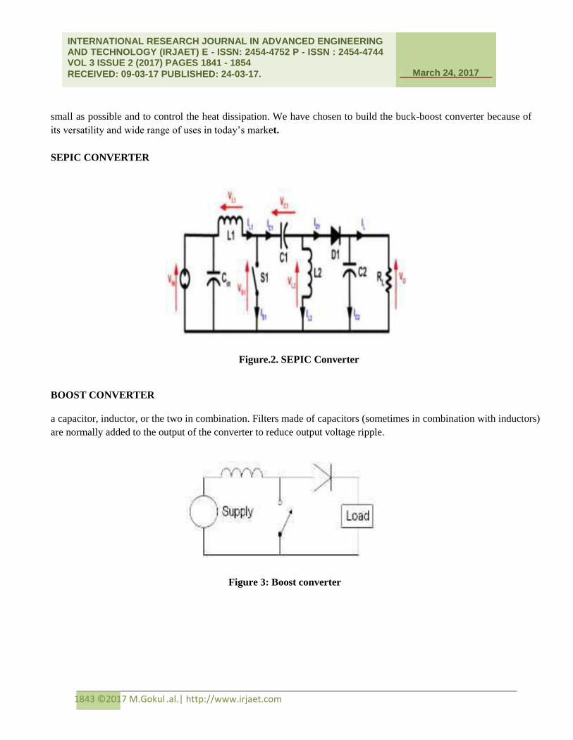
SEPIC CONVERTER
Figure.2. SEPIC Converter
BOOST CONVERTER
a capacitor, inductor, or the two in combination. Filters made of capacitors (sometimes in combination with inductors)
are normally added to the output of the converter to reduce output voltage ripple.
Figure 3: Boost converter
Page 4
March 24, 2017
INTERNATIONAL RESEARCH JOURNAL IN ADVANCED ENGINEERING AND TECHNOLOGY (IRJAET) E - ISSN: 2454-4752 P - ISSN : 2454-4744 VOL 3 ISSUE 2 (2017) PAGES 1841 - 1854
RECEIVED: 09-03-17 PUBLISHED: 24-03-17. March 24, 2017
1844 ©2017 M.Gokul .al.| http://www.irjaet.com
3. OPERATING PRINCIPLE
The key principle that drives the boost converter is the tendency of an inductor to resist changes in current. In a
boost converter, the output voltage is always higher than the input voltage.
(a) When the switch is closed, current flows through the inductor in clockwise direction and the inductor
stores the energy. Polarity of the left side of the inductor is positive.
(b) When the switch is opened, current will be reduced as the impedance is higher. Therefore, change or
reduction in current will be opposed by the inductor. Thus the polarity will be reversed (means left side of
inductor will be negative now). As a result two sources will be in series causing a higher voltage to charge the
capacitor through the diode D.
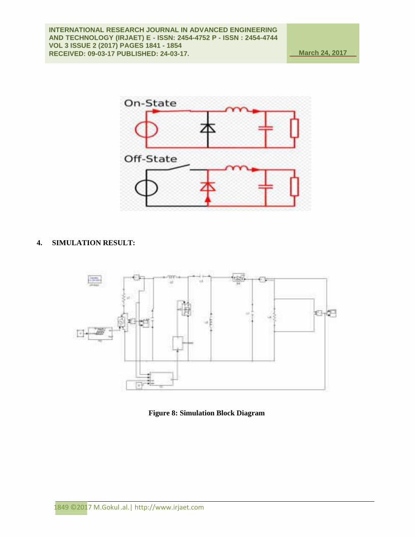
ON STATE
Figure 4: ON State
OFF STATE
Figure 5: OFF State
The basic principle of a Boost converter consists of 2distinct states in the On-state, the switch S is closed,
resulting in an increase in the inductor current;
Page 5
March 24, 2017
INTERNATIONAL RESEARCH JOURNAL IN ADVANCED ENGINEERING AND TECHNOLOGY (IRJAET) E - ISSN: 2454-4752 P - ISSN : 2454-4744 VOL 3 ISSUE 2 (2017) PAGES 1841 - 1854
RECEIVED: 09-03-17 PUBLISHED: 24-03-17. March 24, 2017
1845 ©2017 M.Gokul .al.| http://www.irjaet.com
CONTINUOUS MODE
Figure 6: Waveforms of current and voltage in a boost converter operating in continuous mode.
During the On-state, the switch S is closed, which makes the input voltage ( ) appear across the inductor,
which causes a change in current ( ) flowing through the inductor during a time period (t) by the formula:
Page 6
March 24, 2017
INTERNATIONAL RESEARCH JOURNAL IN ADVANCED ENGINEERING AND TECHNOLOGY (IRJAET) E - ISSN: 2454-4752 P - ISSN : 2454-4744 VOL 3 ISSUE 2 (2017) PAGES 1841 - 1854
RECEIVED: 09-03-17 PUBLISHED: 24-03-17. March 24, 2017
1846 ©2017 M.Gokul .al.| http://www.irjaet.com
At the end of the On-state, the increase of IL is therefore:
D is the duty cycle. It represents the fraction of the commutation period T during which the switch is on.
Therefore D ranges between 0 (S is never on) and 1 (S is always on). During the Off-state, the switch S is open,
so the inductor current flows through the load. If we consider zero voltage drops in the diode, and a capacitor
large enough for its voltage to remain constant, the evolution of IL is:
Therefore, the variation of IL during the Off-period is:
As we consider that the converter operates in steady-state conditions, the amount of energy stored in each of
its components has to be the same at the beginning and at the end of a commutation cycle. In particular, the
energy stored in the inductor is given by:
So, the inductor current has to be the same at the start and end of the commutation cycle. This means the
overall change in the current (the sum of the changes) is zero:
Substituting and by their expressions yields:
This can be written as:
This in turn reveals the duty cycle to be:
Page 7
March 24, 2017
INTERNATIONAL RESEARCH JOURNAL IN ADVANCED ENGINEERING AND TECHNOLOGY (IRJAET) E - ISSN: 2454-4752 P - ISSN : 2454-4744 VOL 3 ISSUE 2 (2017) PAGES 1841 - 1854
RECEIVED: 09-03-17 PUBLISHED: 24-03-17. March 24, 2017
1847 ©2017 M.Gokul .al.| http://www.irjaet.com
The above expression shows that the output voltage is always higher than the input voltage (as the duty
cycle goes from 0 to 1), and that it increases with D, theoretically to infinity as D approaches 1. This is why this
converter is sometimes referred to as a step-up converter.
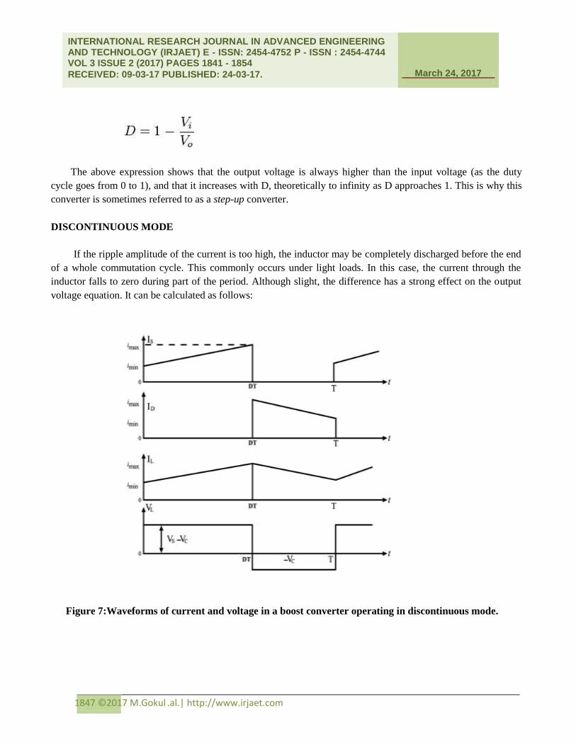
DISCONTINUOUS MODE
If the ripple amplitude of the current is too high, the inductor may be completely discharged before the end
of a whole commutation cycle. This commonly occurs under light loads. In this case, the current through the
inductor falls to zero during part of the period. Although slight, the difference has a strong effect on the output
voltage equation. It can be calculated as follows:
Figure 7:Waveforms of current and voltage in a boost converter operating in discontinuous mode.
Page 8
March 24, 2017
INTERNATIONAL RESEARCH JOURNAL IN ADVANCED ENGINEERING AND TECHNOLOGY (IRJAET) E - ISSN: 2454-4752 P - ISSN : 2454-4744 VOL 3 ISSUE 2 (2017) PAGES 1841 - 1854
RECEIVED: 09-03-17 PUBLISHED: 24-03-17. March 24, 2017
1848 ©2017 M.Gokul .al.| http://www.irjaet.com
As the inductor current at the beginning of the cycle is zero, its maximum value.
During the off-period, IL falls to zero after
:
Using the two previous equations, δ is:
The load current Io is equal to the average diode current (ID). The diode current is equal to the inductor
current during the off-state. Therefore the output current can be written as:
Replacing ILmax and δ by their respective expressions yields:
Therefore, the output voltage gain can be written as follows:
Compared to the expression of the output voltage for the continuous mode, this expression is much more
complicated. Furthermore, in discontinuous operation, the output voltage gain not only depends on the duty
cycle, but also on the inductor value, the input voltage, the switching frequency, and the output current.
Page 9
March 24, 2017
INTERNATIONAL RESEARCH JOURNAL IN ADVANCED ENGINEERING AND TECHNOLOGY (IRJAET) E - ISSN: 2454-4752 P - ISSN : 2454-4744 VOL 3 ISSUE 2 (2017) PAGES 1841 - 1854
RECEIVED: 09-03-17 PUBLISHED: 24-03-17. March 24, 2017
1849 ©2017 M.Gokul .al.| http://www.irjaet.com
4. SIMULATION RESULT:
Figure 8: Simulation Block Diagram
Page 10
March 24, 2017
INTERNATIONAL RESEARCH JOURNAL IN ADVANCED ENGINEERING AND TECHNOLOGY (IRJAET) E - ISSN: 2454-4752 P - ISSN : 2454-4744 VOL 3 ISSUE 2 (2017) PAGES 1841 - 1854
RECEIVED: 09-03-17 PUBLISHED: 24-03-17. March 24, 2017
1850 ©2017 M.Gokul .al.| http://www.irjaet.com
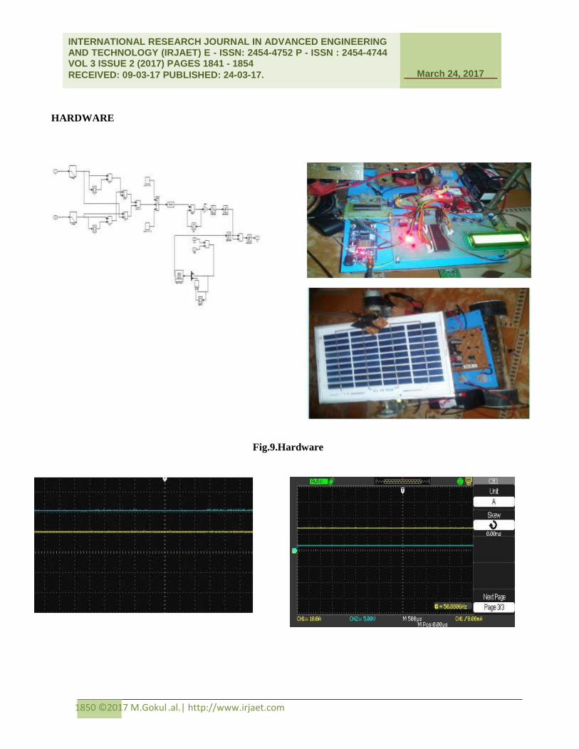
HARDWARE
Fig.9.Hardware
Page 11
March 24, 2017
INTERNATIONAL RESEARCH JOURNAL IN ADVANCED ENGINEERING AND TECHNOLOGY (IRJAET) E - ISSN: 2454-4752 P - ISSN : 2454-4744 VOL 3 ISSUE 2 (2017) PAGES 1841 - 1854
RECEIVED: 09-03-17 PUBLISHED: 24-03-17. March 24, 2017
1851 ©2017 M.Gokul .al.| http://www.irjaet.com
Figure 10: Sepic input voltage and current pv voltage and output voltage (set voltage = 12v)
To turn on an N-channel FET, the gate source voltage must be greater than the inherent threshold voltage i.e.
Vgs>Vth. This implies that in order to turn on transistors Q1, the gate voltage would need to be V phase A +V
th.
In order to isolate the high tension circuit from the digital control PWM signals, an isolation circuit was
implemented at the digital inputs of the PWM signals. The selected isolation is an optically coupled isolator
phototransistor output
IC is shown below.
Page 12
March 24, 2017
INTERNATIONAL RESEARCH JOURNAL IN ADVANCED ENGINEERING AND TECHNOLOGY (IRJAET) E - ISSN: 2454-4752 P - ISSN : 2454-4744 VOL 3 ISSUE 2 (2017) PAGES 1841 - 1854
RECEIVED: 09-03-17 PUBLISHED: 24-03-17. March 24, 2017
1852 ©2017 M.Gokul .al.| http://www.irjaet.com
IC LM7805
Sometimes the input supply line may be noisy. To help smooth out this noise and get a better 5 volt output,
capacitors is usually added to the circuit shown in.
WIEN’S DISPLACEMENT LAW
Wien’s Law tells that objects of different temperature emit spectra that peak at different wavelengths. It
provides the wavelength for maximum spectral radiant emittance for a given temperature.
The relationship between the true temperature of the black body and its peak spectral existence or dominant
wavelength is described by this law
The world is not full of black bodies; rather it comprises of selectively radiating bodies like rocks, water,
etc.
Emissivity depends on object color, surface roughness, moisture content, degree of compaction, field of
view, viewing angle & wavelength.
CONCLUSIONS:-
The Cool Robot successfully rolling resistance was lower than design estimates, suggesting that power
demand on firm Antarctic snow will be less than predicted. Traction tests, both quantitative and qualitative,
Page 13
March 24, 2017
INTERNATIONAL RESEARCH JOURNAL IN ADVANCED ENGINEERING AND TECHNOLOGY (IRJAET) E - ISSN: 2454-4752 P - ISSN : 2454-4744 VOL 3 ISSUE 2 (2017) PAGES 1841 - 1854
RECEIVED: 09-03-17 PUBLISHED: 24-03-17. March 24, 2017
1853 ©2017 M.Gokul .al.| http://www.irjaet.com
provide confidence that the Cool Robot will be able to tow significant science payloads and negotiate commonly
occurring Antarctic sastrugi. Particularly encouraging was the reliable performance of the power control system.
With sufficient solar input, it operated the four solar panels to match their power output with power demand. As
solar input decreased below the match point, it operated all panels at their maximum power points. Although the
snow surface was smooth, the algorithm performed well as the robot executed numerous turns and steering
corrections during which solar insolation varied rapidly. Lastly, the autonomous navigation algorithm performed
reliably during two test lasting 5 – 8 hours. The paper described some of the most conventional methods to store
energy for mobile robot, such as Micro PEM fuel cell systems and ultra-capacitors, showing the advantages and
disadvantages of each one of them. An autonomous mobile robot has been proposed as an efficient design tool
for a system approach. Dedalo 2.0 was converted from a conventional lead-acid battery to a hybrid system based
on PEM Fuel Cell and ultra-capacitors as the power source. The integration of UCaps as elements of energy
storage on the robot was studied with the aim of optimizing the energetic solution. Higher-voltage ultra-
capacitors technology arises on the horizon and the implications are enormously far-reaching.
REFERENCES
[1] D. L. Shirley, ―Mars pathfinder microrover flight experiment—A paradigm for very low-cost spacecraft,‖
Acta Astronaut., vol. 35, pp. 355– 365, 1995.
[2] H. J. Eisen, L. C.Wen, G. Hickey, and D. F. Braun, Sojourner mars rover thermal perfomance,‖ presented at
the 28th Int. Conf. on Environmental Systems, Danvers, MA, 1998.
[3] Stefano, B. V. Ratnakumar,M. C. Smart, G. Halpert, A. Kindler, H. Frank, S. Di, R. Ewell, and S.
Surampudi, Lithium batteries on 2003 mars exploration rover,‖ presented at the IEEE 17thAnnu. Battery
Conf.Applications and Advances, Long Beach, CA, pp. 47–51, 2002.
[4] M. Bajracharya, M. W. Maimone, and D. Helmick, Autonomy for mars rovers: Past, present, and future,‖
Computer, vol. 41, no. 12, pp. 44–50, 2008.
[5] A. K. Baluch, ―Re-use of exomars rover on icy moons of jupiter,‖ M.Sc. thesis, Dept. Space Sci.,
Crandfield Univ., Swindon, U.K., 2010.
[6] The Rover Team, ―The ExoMars rover and Pasteur payload Phase a study: An approach to experimental
astrobiology,‖ Int. J. Astrobiol., vol. 5, no. 3, pp. 221–241, 2006.
[7] J. L. Bresina, M. G. Bualat, L. J. Edwards, R. J. Washington, and A. R. Wright, ―K9 operation in May ’00
dual-rover field experiment,‖ presented at the 6th Int. Symp. Artificial Intelligence, Robotics and Automation
in Space, Montreal, QC, Canada, 2001.
[8] P. S. Schenker, E. T. Baumgartner, P. G. Backes, H. Aghazarian, L. I. Dorsky, J. S. Norris, T. L.
Huntsberger, Y. Cheng, A. Trebi-Ollennu, M. S. Garrett, B. A. Kennedy, and A. J. Ganino,
Page 14
March 24, 2017
INTERNATIONAL RESEARCH JOURNAL IN ADVANCED ENGINEERING AND TECHNOLOGY (IRJAET) E - ISSN: 2454-4752 P - ISSN : 2454-4744 VOL 3 ISSUE 2 (2017) PAGES 1841 - 1854
RECEIVED: 09-03-17 PUBLISHED: 24-03-17. March 24, 2017
1854 ©2017 M.Gokul .al.| http://www.irjaet.com
―FIDO: A field integrated design & operations rover for mars surface exploration,‖ presented at the 6th Int.
Symp. Artificial Intelligence, Robotics and Automation in Space, Quebec, QC, Canada, 2001.
[9] T. Kubota, Y. Kunii, Y. Kuroda, and M. Otsuki, Japanese rover test-bed for lunar exploration,‖ in Proc.
Int. Symp. Artif. Intell., Robot. Automat. Space, no.77, 2008.
[10] M. S. Schneider, A. Bertrand, R. Lamon, P. Siegwart, R. vanWinnendael, and A. Schiele, ―SOLERO:
Solar powered exploration rover,‖ presented at the 7th ESAWorkshop Advanced Space Technologies for
Robotics and Automation, Noordwijk, The Netherlands.