Inomata 1 DEVELOPMENT OF THE POP-UP ENGINE HOOD FOR PEDESTRIAN HEAD PROTECTION Yusuke Inomata Nobuhiro Iwai Yoshinori Maeda Seiichi Kobayashi Hiroyuki Okuyama Nobuhiko Takahashi NISSAN MOTOR CO., LTD., Japan Paper Number 09-0067 ABSTRACT The “Pop-up Engine Hood” helps makes it possible for automobile designers to help reduce head injury during pedestrian impact while maintaining streamlined hood design. Some countries have adopted pedestrian protection regulation and there is an on-going discussion in the United Nations WP29 about Global Technical Regulations (gtr) and there is a possibility such regulations may be enhanced in the future. Many car manufacturers have been planning to improve pedestrian safety by various technical applications. In general, pedestrian head protection is achieved by creating space between the hood (which is deformable) and the engine component (which is not). However, this concept is difficult to apply to some vehicles, especially low engine hood vehicles, such as coupes and sport cars. The “Pop-up Engine Hood System” which has recently been used in mass production vehicles in Japan may help with this issue. This paper will describe the system outline and key technologies incorporated in the system e.g.: - Effectiveness of injury reduction mechanism (evaluated using CAE analysis and tests) when a pedestrian contacts directly above or near the actuator, which lifts up the hood. - Technique to help reduce the dispersion of head injury due to hood vibration during the hood raising process. - Human kinematics during system operation evaluated by using Polar-II dummy (currently available as a pedestrian full scale dummy), and human body FE model. INTRODUCTION There were 6,639 traffic accident fatalities in Japan in 2007. [1] The number of fatalities has been on a downward trend for many years, but pedestrian fatalities now account for more than 30% of the total and are almost equal to vehicle occupant fatalities (Fig. 1). At the result of governmental efforts concerning pedestrian protection, the regulation (e.g. EEC 2003/102) has been adopted in Europe and Japan beginning 2005. The United Nations is also proceeding with the work of developing Global Technical Regulations (gtr). Other countries around the world are also examining the introduction of pedestrian protection regulations. Figure 1. Ratio of traffic accident fatalities in Japan in 2007. Head injuries are the main cause of pedestrian fatalities. [2] One factor is the presence of high-stiffness parts such as the engine and battery in the engine compartment. After a pedestrian's head strikes the engine hood in the primary impact, the risk of head injury increases due to a secondary impact with such high-stiffness parts. One general design measure adopted in recent years is to raise the height of the hood so as to secure more buffer space above high-stiffness parts after the primary impact. This measure reduces the risk of head injury because it can help prevent a secondary impact by using the extra space to absorb the kinetic energy of a pedestrian's
Transcript
Inomata 1
DEVELOPMENT OF THE POP-UP ENGINE HOOD FOR PEDESTRIAN HEAD PROTECTION Yusuke Inomata Nobuhiro Iwai Yoshinori Maeda Seiichi Kobayashi Hiroyuki Okuyama Nobuhiko Takahashi NISSAN MOTOR CO., LTD., Japan Paper Number 09-0067 ABSTRACT The “Pop-up Engine Hood” helps makes it possible for automobile designers to help reduce head injury during pedestrian impact while maintaining streamlined hood design. Some countries have adopted pedestrian protection regulation and there is an on-going discussion in the United Nations WP29 about Global Technical Regulations (gtr) and there is a possibility such regulations may be enhanced in the future. Many car manufacturers have been planning to improve pedestrian safety by various technical applications. In general, pedestrian head protection is achieved by creating space between the hood (which is deformable) and the engine component (which is not). However, this concept is difficult to apply to some vehicles, especially low engine hood vehicles, such as coupes and sport cars. The “Pop-up Engine Hood System” which has recently been used in mass production vehicles in Japan may help with this issue. This paper will describe the system outline and key technologies incorporated in the system e.g.: - Effectiveness of injury reduction mechanism (evaluated using CAE analysis and tests) when a pedestrian contacts directly above or near the actuator, which lifts up the hood. - Technique to help reduce the dispersion of head injury due to hood vibration during the hood raising process. - Human kinematics during system operation evaluated by using Polar-II dummy (currently available as a pedestrian full scale dummy), and human body FE model. INTRODUCTION There were 6,639 traffic accident fatalities in Japan in 2007.[1] The number of fatalities has been on a downward trend for many years, but pedestrian
fatalities now account for more than 30% of the total and are almost equal to vehicle occupant fatalities (Fig. 1). At the result of governmental efforts concerning pedestrian protection, the regulation (e.g. EEC 2003/102) has been adopted in Europe and Japan beginning 2005. The United Nations is also proceeding with the work of developing Global Technical Regulations (gtr). Other countries around the world are also examining the introduction of pedestrian protection regulations.
Figure 1. Ratio of traffic accident fatalities in Japan in 2007. Head injuries are the main cause of pedestrian fatalities.[2] One factor is the presence of high-stiffness parts such as the engine and battery in the engine compartment. After a pedestrian's head strikes the engine hood in the primary impact, the risk of head injury increases due to a secondary impact with such high-stiffness parts. One general design measure adopted in recent years is to raise the height of the hood so as to secure more buffer space above high-stiffness parts after the primary impact. This measure reduces the risk of head injury because it can help prevent a secondary impact by using the extra space to absorb the kinetic energy of a pedestrian's
Inomata 2
head. However, it is difficult to apply to some vehicles, especially low engine hood vehicles, such as coupes and sport cars. The pop-up engine hood presented here has been developed to help resolve this issue by immediately raising the rear of the hood approximately 100 mm upon detection of a collision with a pedestrian. This pop-up engine hood has recently been installed on a production vehicle having limited space under the hood. This paper explain the system configuration and the newly developed techniques.[3] It especially describes the energy absorbing mechanism of the actuators, the method used to reduce the dispersion of head injury due to hood vibration, and the results of tests conducted with a pedestrian dummy and using human body FE model to verify the operation of the system. Pop-up Engine Hood System This section describes the basic structure and mechanisms of the pop-up engine hood system. As illustrated in Fig. 2, the system consists of the following three basic components.
Figure 2. System overview.
(1) Sensors : Detect a collision between the vehicle and a pedestrian. (2) Control unit : Judge the necessity of raising the hood. (3) Actuators : Raise the rear of the hood. The function of each component is explained in detail below.
Sensors - Three sensors for detecting a collision with a pedestrian are installed behind the front bumper fascia as shown in Fig. 3. This structure was adopted because the front bumper is usually the first part to come in contact with a pedestrian's body in a collision with a vehicle.[4] The sensors are positioned on the right and left sides and in the center. The sensors function to detect a change in acceleration and have experience of use as the airbag sensors. These devices detect the movement of the bumper fascia caused by contact with a pedestrian's legs.
Figure 3. Sensor for pedestrian detection.
Control Unit - The flowchart in Fig. 4 shows the
sequence of events involved in the judgment made by the control unit. The control unit judges the necessity of raising the hood based on the detection signals from the three sensors and also the vehicle velocity at the time of a collision. The use of this judgment logic achieves reliable system deployment in the vehicle velocity range where it is necessary to raise the hood.
Figure 4. Flow chart of sensor.
Actuators - The actuators that provide the
driving force for raising the rear of the hood are constructed with an extendable cylinder operated by pyrotechnics. As shown in Fig. 5, the length of the three-stage cylinder before operation is less than one-half of its extended size.
Figure 5. Actuator.
Inomata 3
Figure 6 shows the relationship between the operation of the actuators and the hood hinges for opening/closing the hood. Normally, the hood opens or closes by rotating upward or downward centered on the hood hinges (Fig. 6 (a) and (b)). In contrast, when the pop-up system is deployed, the rear of the hood is raised centered on the hood lock at the front of the vehicle (Fig. 6 (c)).
Figure 6. Operation of hinge and actuator.
A detailed diagram of the hood hinge mechanism is shown in Fig. 7. During normal opening or closing of the hood, the lock lever fixes link (a) and link (b), allowing only link (a) to rotate. When the pop-up hood system is deployed, the actuator head presses on the lock lever, allowing link (b) to rotate. The actuator cylinder extends to raise the rear of the hood, with the hood lock serving as the fulcrum of the hood's upward rotation. As a result of these operations, the rear of the hood is raised by approximately 100 mm to secure buffer space between the hood and the high-stiffness parts beneath it.
Figure 7. Pop-up mechanism of hood hinge.
Following the extension of the actuators, the rear of the hood is supported on each side by a ball lock mechanism built into the cylinders to prevent them from returning to their original state (Fig. 5). In the
event of a collision with a pedestrian, primarily this mechanism enables the actuator cylinders to support the rear of the hood. The system is constructed such that in certain impacts the pedestrian's kinetic energy is absorbed by the primary impact and a secondary impact with the engine compartment components is avoided. Secondarily the ball lock mechanism also has a collapsible structure that allows the cylinders to retract again if force above a certain threshold is applied. This helps to reduce the risk of injury in the event a pedestrian collides with the hood directly above or near the actuators.
Collapsible Mechanism of Actuators - This section presents an example of numerical simulations[5],
[6] that were conducted to validate the effectiveness of the collapsible mechanism of the actuators. These simulations were performed with the PAM-CRASH software using a headform impactor. Figure 8 shows acceleration histories of the headform impactor when it struck the hood surface near one of the actuators. The impactor acceleration is indicated along the vertical axis in relation to its displacement along the horizontal axis. The solid line is for a pop-up hood system with collapsible actuators and the dashed line is for a system with rigid actuators. The waveform for the system without the collapsible mechanism indicates that, following the initial peak for the primary impact with the hood surface, the secondary impact with the actuator produced a relatively large acceleration peak. In contrast, the waveform for the system with the collapsible mechanism indicates that the actuators initially supported the rear of the hood until the preset load was reached, after which the collapsible mechanism worked to avoid another increase in impactor acceleration. As a result, the system with the collapsible mechanism kept the subsequent impactor acceleration below that of the level of the primary impact with the hood, thereby verifying the effectiveness of this mechanism.
Figure 8. Example of acceleration history of headform impactor.
Inomata 4
System Deployment
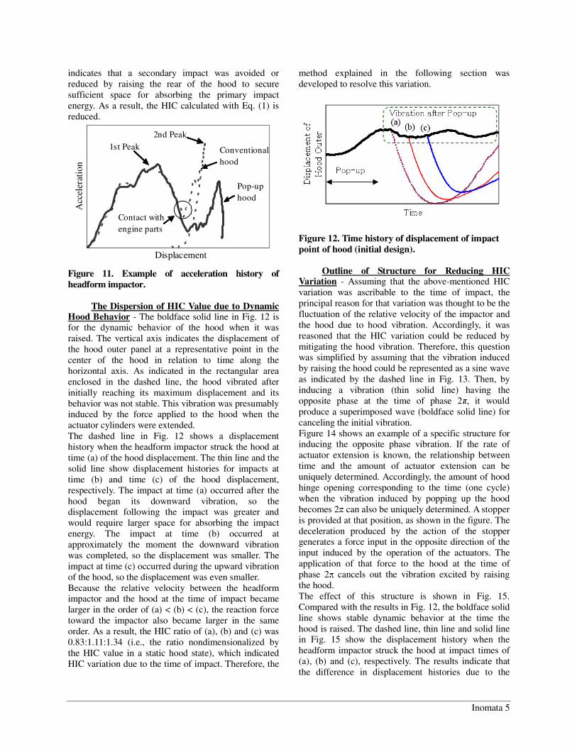
Targeted System Deployment Time - On a time line of a vehicle-to-pedestrian collision, the earliest event is when the bumper strikes the pedestrian's legs and the final event is when the head strikes the hood. This time interval from bumper contact with the legs to the head's striking the hood is called the head impact time (HIT). The deployment criteria is to have complete deployment of the pop-up hood system sufficiently earlier than HIT. In developing this system, HIT was calculated by conducting simulations using a pedestrian model, an approach shown to be suitable on the basis of the research done by Ishikawa, H., et al.[7] HIT is mainly influenced by the front-end geometry of a vehicle and a pedestrian's physique. Accordingly, simulations were conducted using pedestrian models with different physiques to calculate HIT values for vehicle front-end geometry considered (Fig. 9). A specific example is presented here to explain the procedure for calculating the targeted time for completion of pop-up hood deployment. For the vehicle front-end geometry considered here, HIT of a 50th percentile adult male is assumed to be 1.0. Accordingly, HIT of the 5th percentile adult female is 0.67 and that of the 6 years old child is 0.38. This smallest HIT value for the 6 years old child was adopted as the targeted completion time for system deployment.
Figure 9. Example of car to pedestrian dummy collision simulation.
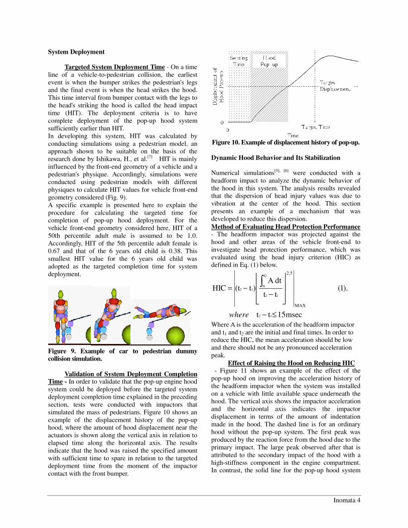
Validation of System Deployment Completion Time - In order to validate that the pop-up engine hood system could be deployed before the targeted system deployment completion time explained in the preceding section, tests were conducted with impactors that simulated the mass of pedestrians. Figure 10 shows an example of the displacement history of the pop-up hood, where the amount of hood displacement near the actuators is shown along the vertical axis in relation to elapsed time along the horizontal axis. The results indicate that the hood was raised the specified amount with sufficient time to spare in relation to the targeted deployment time from the moment of the impactor contact with the front bumper.
Figure 10. Example of displacement history of pop-up. Dynamic Hood Behavior and Its Stabilization Numerical simulations[5], [6] were conducted with a headform impact to analyze the dynamic behavior of the hood in this system. The analysis results revealed that the dispersion of head injury values was due to vibration at the center of the hood. This section presents an example of a mechanism that was developed to reduce this dispersion. Method of Evaluating Head Protection Performance - The headform impactor was projected against the hood and other areas of the vehicle front-end to investigate head protection performance, which was evaluated using the head injury criterion (HIC) as defined in Eq. (1) below.
15msectt
).1(tt
dtA )t(tHIC
12
12
2
112
MAX
2.5t
t
≤−
⎥⎥⎥
⎦
⎤
⎢⎢⎢
⎣
⎡
−−= ∫
where
Where A is the acceleration of the headform impactor and t1 and t2 are the initial and final times. In order to reduce the HIC, the mean acceleration should be low and there should not be any pronounced acceleration peak.
Effect of Raising the Hood on Reducing HIC - Figure 11 shows an example of the effect of the pop-up hood on improving the acceleration history of the headform impactor when the system was installed on a vehicle with little available space underneath the hood. The vertical axis shows the impactor acceleration and the horizontal axis indicates the impactor displacement in terms of the amount of indentation made in the hood. The dashed line is for an ordinary hood without the pop-up system. The first peak was produced by the reaction force from the hood due to the primary impact. The large peak observed after that is attributed to the secondary impact of the hood with a high-stiffness component in the engine compartment. In contrast, the solid line for the pop-up hood system
Inomata 5
indicates that a secondary impact was avoided or reduced by raising the rear of the hood to secure sufficient space for absorbing the primary impact energy. As a result, the HIC calculated with Eq. (1) is reduced.
Displacement
Acc
eler
atio
n
Pop-uphood
Conventionalhood
Contact withengine parts
1st Peak2nd Peak
Figure 11. Example of acceleration history of headform impactor.
The Dispersion of HIC Value due to Dynamic Hood Behavior - The boldface solid line in Fig. 12 is for the dynamic behavior of the hood when it was raised. The vertical axis indicates the displacement of the hood outer panel at a representative point in the center of the hood in relation to time along the horizontal axis. As indicated in the rectangular area enclosed in the dashed line, the hood vibrated after initially reaching its maximum displacement and its behavior was not stable. This vibration was presumably induced by the force applied to the hood when the actuator cylinders were extended. The dashed line in Fig. 12 shows a displacement history when the headform impactor struck the hood at time (a) of the hood displacement. The thin line and the solid line show displacement histories for impacts at time (b) and time (c) of the hood displacement, respectively. The impact at time (a) occurred after the hood began its downward vibration, so the displacement following the impact was greater and would require larger space for absorbing the impact energy. The impact at time (b) occurred at approximately the moment the downward vibration was completed, so the displacement was smaller. The impact at time (c) occurred during the upward vibration of the hood, so the displacement was even smaller. Because the relative velocity between the headform impactor and the hood at the time of impact became larger in the order of (a) < (b) < (c), the reaction force toward the impactor also became larger in the same order. As a result, the HIC ratio of (a), (b) and (c) was 0.83:1.11:1.34 (i.e., the ratio nondimensionalized by the HIC value in a static hood state), which indicated HIC variation due to the time of impact. Therefore, the
method explained in the following section was developed to resolve this variation.
Figure 12. Time history of displacement of impact point of hood (initial design).
Outline of Structure for Reducing HIC Variation - Assuming that the above-mentioned HIC variation was ascribable to the time of impact, the principal reason for that variation was thought to be the fluctuation of the relative velocity of the impactor and the hood due to hood vibration. Accordingly, it was reasoned that the HIC variation could be reduced by mitigating the hood vibration. Therefore, this question was simplified by assuming that the vibration induced by raising the hood could be represented as a sine wave as indicated by the dashed line in Fig. 13. Then, by inducing a vibration (thin solid line) having the opposite phase at the time of phase 2π, it would produce a superimposed wave (boldface solid line) for canceling the initial vibration. Figure 14 shows an example of a specific structure for inducing the opposite phase vibration. If the rate of actuator extension is known, the relationship between time and the amount of actuator extension can be uniquely determined. Accordingly, the amount of hood hinge opening corresponding to the time (one cycle) when the vibration induced by popping up the hood becomes 2π can also be uniquely determined. A stopper is provided at that position, as shown in the figure. The deceleration produced by the action of the stopper generates a force input in the opposite direction of the input induced by the operation of the actuators. The application of that force to the hood at the time of phase 2π cancels out the vibration excited by raising the hood. The effect of this structure is shown in Fig. 15. Compared with the results in Fig. 12, the boldface solid line shows stable dynamic behavior at the time the hood is raised. The dashed line, thin line and solid line in Fig. 15 show the displacement history when the headform impactor struck the hood at impact times of (a), (b) and (c), respectively. The results indicate that the difference in displacement histories due to the
Inomata 6
impact time has been reduced. That resulted in a HIC ratio in this example of 1.05:0.97:1.01, indicating that the variation in head injury values was also reduced. The proposed structure is effective if the onset of deceleration occurs near the vibration phase 2π. The time when the vibration phase is 2π is determined almost entirely by the natural vibration frequency of the hood. Therefore, this structure can stably reduce hood vibration under various real-world conditions.
Time
Dis
plac
emen
t
Initial waveSecondary waveSuperimposed wave
2π
Figure 13. Cancellation of vibration by superposition.
Figure 14. Example of hood hinge structure.
Figure 15. Time history of displacement of impact point of hood (robust design).
System Validation Using a Pedestrian Dummy This section describes an example of the validation of the operation of the pop-up engine hood system using a Polar-II pedestrian dummy.[8], [9]
Test Conditions - The validation example described here is for a vehicle impact speed of 35 km/h. As shown in Fig. 16, the dummy was set in a walking pedestrian stance (WP2) as defined in IHRA/PS 215. The dummy was positioned such that the center of its head was at the centerline of the vehicle laterally.
Figure 16. Dummy setting.
Validation of System Operation - Figure 17
shows the dummy's behavior at the time deployment of the actuators was completed. The dummy's upper body has not moved clearly from its initial condition. It is clear that the deployment of the pop-up hood was completed sufficiently in advance of the subsequent impact of the dummy's head against the hood. The dummy's behavior at the moment of shoulder contact with the hood is shown in Fig. 18. At this time, the extended actuators were holding the hood at a higher position above the engine compartment components. It is clear that the system secured the necessary buffer space for absorbing the head's impact energy. This test verified that the series of operations explained in the previous section were completed according to the intention of the system design, even under these conditions of an actual car-to-pedestrian accident.
Inomata 7
Figure 17. Dummy behavior after actuator operation.
Figure 18. Dummy behavior before head contact.
Validation of System Deployment by Using Human Body FE Model
This section describes an example of validation of the system operation and confirmation of the effect on potential injury by using human body FE model. This human body FE model(10) is based on the model that is developed by Japan Automobile Manufacturers Association (JAMA). Joint development by Japanese car manufacturers recently started because the human body FE model can be used by all car manufacturers. In Japan, JAMA coordinates Japan Automobile Research Institute (JARI) and domestic car manufacturers will work jointly to develop the future human body FE model.
The application the human body FE model to evaluate the pop-up engine hood system that is mounted on the coupe style vehicle is presented here. The numerical simulation introduced here is for the final validation of the system operation in more practical condition. Fig. 19 shows an outline of the simulation. The representative parameter is “with” or “without” pop-up engine hood system in this simulation.
As a representative simulation example in more practical condition, the vehicle speed is set to 40km/h. The relation between pedestrian behavior and hood pop-up is validated. Fig. 20 shows behavior of human body FE model. This example shows that it is clear that the deployment of the pop-up engine hood was completed sufficiently in advance of the subsequent impact of the head against the hood.
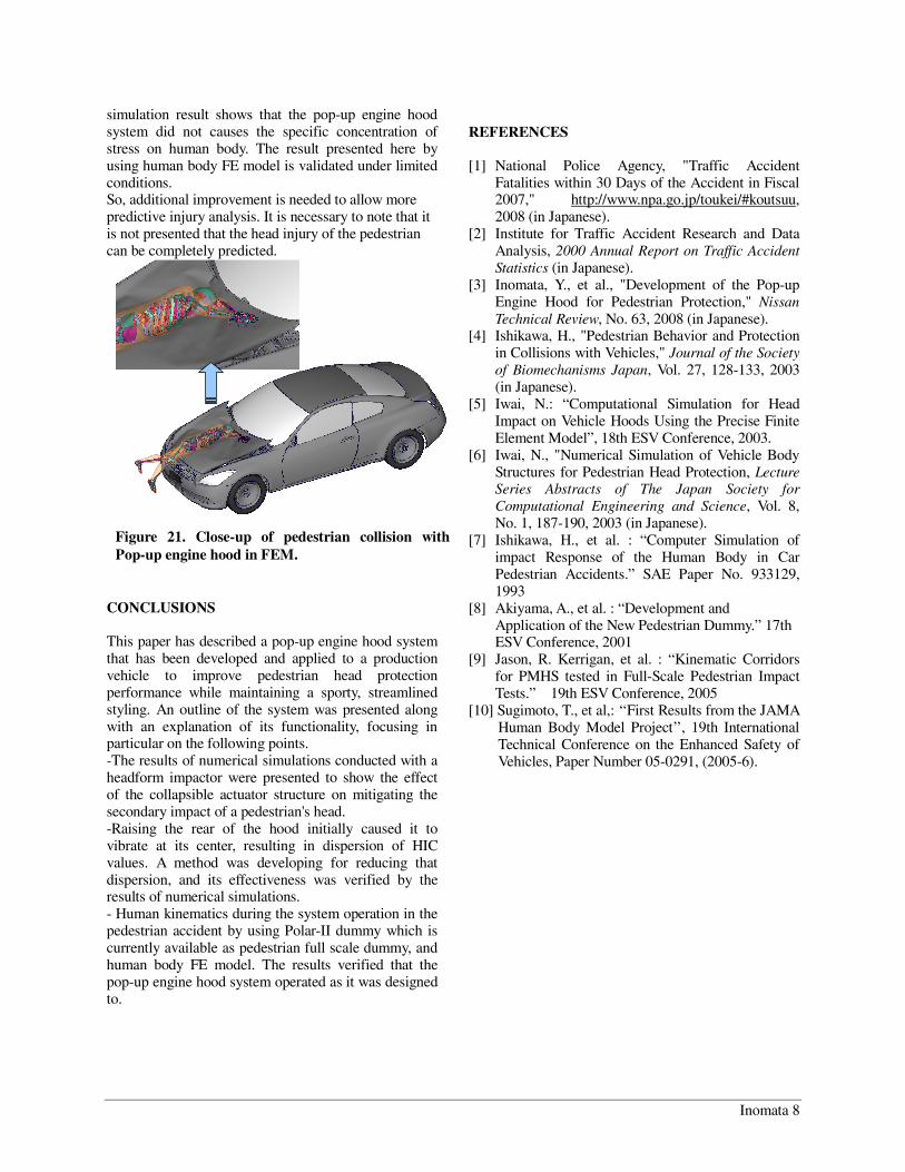
Fig. 21 shows the head contact behavior after the full deployment. At this time, the extended actuators were holding the hood at a higher position above the engine compartment components. It is clear that the system secured the necessary buffer space for absorbing the head's impact energy. The simulation result of the pedestrian behavior by using human body FE model is described under the condition showing in Fig. 19. Additionally, this
Vehicle Model
Impact V 40 km/h
Human Body Model
Height+ 172 cm Weight 71.9 kg # of Nodes 66,249 # of Elems. 95,304 + in a walking posture
Figure 19. Simulation model setup of pedestrian collision with vehicle with Pop-up engine hood.
25msec Time at full deployment
75msec 100msec Figure 20. A simulation (FEM) result of pedestrian collision with Pop-up engine hood.
Inomata 8
simulation result shows that the pop-up engine hood system did not causes the specific concentration of stress on human body. The result presented here by using human body FE model is validated under limited conditions. So, additional improvement is needed to allow more predictive injury analysis. It is necessary to note that it is not presented that the head injury of the pedestrian can be completely predicted.
CONCLUSIONS This paper has described a pop-up engine hood system that has been developed and applied to a production vehicle to improve pedestrian head protection performance while maintaining a sporty, streamlined styling. An outline of the system was presented along with an explanation of its functionality, focusing in particular on the following points. -The results of numerical simulations conducted with a headform impactor were presented to show the effect of the collapsible actuator structure on mitigating the secondary impact of a pedestrian's head. -Raising the rear of the hood initially caused it to vibrate at its center, resulting in dispersion of HIC values. A method was developing for reducing that dispersion, and its effectiveness was verified by the results of numerical simulations. - Human kinematics during the system operation in the pedestrian accident by using Polar-II dummy which is currently available as pedestrian full scale dummy, and human body FE model. The results verified that the pop-up engine hood system operated as it was designed to.
REFERENCES [1] National Police Agency, "Traffic Accident
Fatalities within 30 Days of the Accident in Fiscal 2007," http://www.npa.go.jp/toukei/#koutsuu, 2008 (in Japanese).
[2] Institute for Traffic Accident Research and Data Analysis, 2000 Annual Report on Traffic Accident Statistics (in Japanese).
[3] Inomata, Y., et al., "Development of the Pop-up Engine Hood for Pedestrian Protection," Nissan Technical Review, No. 63, 2008 (in Japanese).
[4] Ishikawa, H., "Pedestrian Behavior and Protection in Collisions with Vehicles," Journal of the Society of Biomechanisms Japan, Vol. 27, 128-133, 2003 (in Japanese).
[5] Iwai, N.: “Computational Simulation for Head Impact on Vehicle Hoods Using the Precise Finite Element Model”, 18th ESV Conference, 2003.
[6] Iwai, N., "Numerical Simulation of Vehicle Body Structures for Pedestrian Head Protection, Lecture Series Abstracts of The Japan Society for Computational Engineering and Science, Vol. 8, No. 1, 187-190, 2003 (in Japanese).
[7] Ishikawa, H., et al. : “Computer Simulation of impact Response of the Human Body in Car Pedestrian Accidents.” SAE Paper No. 933129, 1993
[8] Akiyama, A., et al. : “Development and Application of the New Pedestrian Dummy.” 17th ESV Conference, 2001
[9] Jason, R. Kerrigan, et al. : “Kinematic Corridors for PMHS tested in Full-Scale Pedestrian Impact Tests.” 19th ESV Conference, 2005
[10] Sugimoto, T., et al,: ‘‘First Results from the JAMA Human Body Model Project’’, 19th International Technical Conference on the Enhanced Safety of Vehicles, Paper Number 05-0291, (2005-6).
Figure 21. Close-up of pedestrian collision with Pop-up engine hood in FEM.