1 Hitachi Research Laboratory, Hitachi, Ltd.* 3-1-1 Saiwai, Hitachi, Ibaraki 317-0073, JAPAN
2 Hitachi Works, Power Systems Company, Hitachi, Ltd.*
* Mitsubishi Hitachi Power Systems, Ltd. since Feb. 2014
ABSTRACT Reduced exhaust loss by an increase in the exhaust annulus area improves the thermal efficiency of steam turbines, such as 1000MW-class turbines. To cut this loss, the 3600rpm-50inch and 3000rpm-60inch last stage blades have been developed, getting one of the world’s largest exhaust annulus areas in the turbines. Three main problems are associated with long blades: large centrifugal stress, high Mach number flow, and low rigidity. To reduce the centrifugal stress, titanium alloy was applied for the blade material; it has higher specific strength than steel. Turbulent flow analyses were utilized to clarify the complex flow phenomena including shock waves. Variations in the flow passage area formed between blades were designed in accordance with Mach number which minimized losses caused by shock waves. The continuous covered blade structure, in which blades are interconnected with shroud covers at the tip and tie-bosses at the mid-span, increased the rigidity and vibrational damping.
NOMENCLATURE Aan annulus area AVN advanced vortex nozzle (tangential leaned nozzle) a sound velocity BR boss ratio (hub to tip radius ratio) c absolute velocity h specific enthalpy M Mach number p static pressure Rec,2 Reynolds number based on chord length and
outlet velocity Rx stage reaction r radius U blade peripheral speed w relative velocity h stage specific enthalpy drop angular velocity
Subscripts B bucket (moving blade) H hub N nozzle (stationary blade) T tip r radial direction x axial direction tangential direction
INTRODUCTION Steam turbines provide electric power generation in various types of power plants, including combined cycle and coal-fired fossil power plants and nuclear power plants. Steam turbines are able to utilize thermal energy regardless of the type of heat sources. In addition, steam turbines effectively extract the energy until the temperature of the steam drops to almost the ambient temperature because steam can generate a low pressure of several kPa at the outlet due to water condensation. These features ensure that steam turbines are also applied in cogeneration plants and will remain important machines for years to come. Steam turbines need to cover a wide range of power outputs from a few to 1500MW, in order to apply them to the various types of power plants. The last stage blades most significantly affect the power output, size and thermal efficiency of steam turbines; therefore designing a wide selection of last stage blades is im-portant. For many years, Hitachi, Ltd. has been developing last stage blades which have been operating reliably in power plants worldwide (Machida et al, 2002). In addition to the company’s current lineup, the authors have recently developed a much longer last stage blade which has one of the world’s largest exhaust an-nulus areas. An increase of the annulus area of the last stage in steam turbines brings three main benefits: increased power output, improved efficiency, and reduced axial length. When the average axial ve-locity at the outlet of a larger last stage is almost the same as that of the original last stage, a larger annulus area leads to a larger mass flow rate. In turn, the power output can be increased by the in-creased mass flow rate. When the mass flow rate is almost the same as that of the original turbine, a larger annulus area leads to a smaller average axial velocity at the outlet of the last stage. The efficiency can be improved by reducing the amount of useless kinetic energy. The number of cylinders can be reduced when increment of the annulus area compensates for the annulus area of the original blade. On the other hand, some technical issues need to be resolved to increase the length of the last blade. One of the aerodynamic problems is supersonic inflow (Stüer et al., 2005). Conventionally, outflow Mach numbers are supersonic near the tip of some long blades. Inflow Mach numbers near the tip also become supersonic when the blade is lengthened more. In such cases, it is difficult to avoid emergence of shock waves upstream from the cascade. The shock waves increase kinetic energy loss by themselves and may cause boundary layer separation which leads to another kinetic energy loss. This paper describes development of the last stage blade and in particular considers how to avoid losses caused by supersonic inflow accompanying longer blades.
International Journal of Gas Turbine, Propulsion and Power Systems October 2014, Volume 6, Number 2
Presented at International Gas Turbine Congress 2011 Osaka, November 13-18, Osaka, Japan, IGTC2011-249 Review Completed on May 30, 2014
9
OPERATING RANGE The main purpose of developing this new last stage blade is to realize a 1000MW-class steam turbine in the 4-flow configuration, as shown in Fig.1. Typical operating ranges in single-flow, dou-ble-flow and 4-flow configurations are shown in Fig.2. When the rotational speed is 3600 rpm and the exhaust pressure is 5 kPa which is typical for sea-water-cooled units in Japan, operating ranges are as shown in Fig.2 (a). When the rotational speed is 3000 rpm and the exhaust pressure is 3 kPa which is typical in Europe, operating ranges are as shown in Fig.2 (b). The turbine output of 3000rpm machine with 3 kPa condition is less than that of 3600rpm machine with 5 kPa condition, because smaller density at 3 kPa results in larger annulus velocity which decides applicable operat-ing ranges. To realize these target operating ranges, the annulus areas of the new last stage blade are 11.5 m2 for a 3600rpm unit and 16.5 m2 for a 3000rpm unit. The annulus areas of existing last stage blades are taken into account to determine the annulus area of the new blades, which can cover 1000MW output in the 4-flow configuration. The blade for the 3000rpm unit is similarly enlarged to 1.2 times the blade for the 3600rpm unit.
SPECIFICATIONS The boss ratio is defined as the hub to tip radius ratio and it is determined using a limit diagram like that shown in Fig.3. The four arrows indicate preferable directions for the four limit values. Gyarmathy and Schlachter (1988) proposed five design limit curves as relationships between the exhaust annulus area and the boss ratio based on simple mechanical engineering formulae: rotor stress, cascade geometry and blade stress, erosion, blade frequency, and stage reaction. The blade frequency is a limitation for a free standing blade and can be ignored in this case, because the con-tinuous covered blade structure, in which blades are interconnected with shroud covers at the tip and tie-bosses at the mid-span, in-creases the rigidity and natural frequency. As for the stage reaction limitation, both too low and too high a stage reaction should be avoided to keep flow losses within acceptable limits. But their stage reaction limitation can be ignored because the local stage reaction can be controlled by using a three-dimensional stage design as is described later.
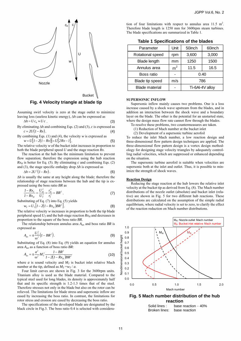
The supersonic inflow limitation is added to the three limit curves. It restricts the maximum inlet relative Mach number at the blade tip to avoid strong shock waves upstream from the blades. The velocity triangle between nozzles (stationary blades) and buckets (moving blades) at the tip is shown in Fig.4. The nozzle outlet velocity c is low at the tip, because static pressure of the nozzle outlet is high due to the swirl velocity. On the other hand, the blade peripheral speed U is high; therefore the relative velocity at the bucket inlet w flows in the opposite direction of the absolute velocity. The relative Mach number at the bucket inlet reaches the supersonic range when the blade length exceeds some threshold. The formulation of the supersonic inflow limitation in the rela-tionship between the annulus area and boss ratio is derived as follows. The relative velocity of the bucket inlet w can be ap-proximated by the difference between the blade peripheral speed U and absolute velocity c,
cUw (1)where the axial velocity can be ignored because it is much smaller than the tangential velocity. The absolute velocity c can be ex-pressed using the stage specific enthalpy drop h and stage reaction Rx as
Assuming swirl velocity is zero at the stage outlet to minimize leaving loss (useless kinetic energy), h can be expressed as
cUcUh . (3)
By eliminating h and combining Eqs. (2) and (3), c is expressed as Rx1U2c . (4)
By combining Eqs. (1) and (4), the velocity w is expressed as 1Rx2URx121Uw . (5)
The relative velocity w of the bucket inlet increases in proportion to both the blade peripheral speed U and the stage reaction Rx. The reaction at the hub has the minimum limitation to prevent flow separation; therefore the expression using the hub reaction RxH is better for Eq. (5). By eliminating c and combining Eqs. (2) and (3), the stage specific enthalpy droph is expressed as
Rx1U2h 2 . (6)
h is usually the same at any height along the blade; therefore the relationship of stage reactions between the hub and the tip is ex-pressed using the boss ratio BR as
2
2T
2H
2T
2H
H
T BRr
r
U
U
Rx1
Rx1
. (7)
Substituting of Eq. (7) into Eq. (5) yields 2
HTT BRRx121Uw . (8)
The relative velocity w increases in proportion to both the tip blade peripheral speed UT and the hub stage reaction RxH and decreases in proportion to the square of the boss ratio BR. The relationship between annulus area Aan and boss ratio BR is expressed as
2
2
2T
an BR1U
A
. (9)
Substituting of Eq. (8) into Eq. (9) yields an equation for annulus area Aan as a function of boss ratio BR:
2H
22T2
2
an BRRx121
BR1M
aA
(10)
where a is sound velocity and MT is bucket inlet relative Mach number at the tip, defined as MT =wT / a. Four limit curves are shown in Fig. 3 for the 3600rpm units. Titanium alloy is used as the blade material. Compared to the typical steel used for long blades, its density is approximately half that and its specific strength is 1.2-1.3 times that of the steel. Therefore stresses not only in the blade but also on the rotor can be relieved. The limitations for blade stress and supersonic inflow are eased by increasing the boss ratio. In contrast, the limitations for rotor stress and erosion are eased by decreasing the boss ratio. The specifications of the developed blade are designated by the black circle in Fig.3. The boss ratio 0.4 is selected with considera-
tion of four limitations with respect to annulus area 11.5 m2. Therefore blade length is 1250 mm for 3600rpm steam turbines. The blade specifications are summarized in Table 1. SUPERSONIC INFLOW Supersonic inflow mainly causes two problems. One is a loss increase caused by a shock wave upstream from the blades, and in addition an interaction between the shock wave and a boundary layer on the blade. The other is the potential for an unstarted state, where the design mass flow rate cannot flow through the blades. To resolve these problems, two countermeasures are taken. (1) Reduction of Mach number at the bucket inlet (2) Development of a supersonic turbine aerofoil To reduce the inlet Mach number, a low reaction design and three-dimensional flow pattern design techniques are applied. The three-dimensional flow pattern design is a vortex design method-ology for designing stage velocity triangles by adequately control-ling radial velocities, which are suppressed or enhanced depending on the situation. The supersonic turbine aerofoil is suitable when velocities are supersonic both at the inlet and outlet. Thus, it is possible to min-imize the strength of shock waves. Reaction Design Reducing the stage reaction at the hub lowers the relative inlet velocity at the bucket tip as derived from Eq. (8). The Mach number distributions of the nozzle outlet (absolute) and bucket inlet (rela-tive) are shown in Fig. 5 for two different hub reactions. These distributions are calculated on the assumption of the simple radial equilibrium, where radial velocity is set to zero, to clarify the effect of the reaction reduction on Mach number distributions.
Fig. 4 Velocity triangle at blade tip
c c
w
U
Nozzle
Bucket
Parameter Unit 50inch 60inch
Rotational speed rpm 3,600 3,000
Blade length mm 1250 1500
Annulus area m2 11.5 16.5
Boss ratio -
Blade tip speed m/s
Blade material -
0.40
786
Ti-6Al-4V alloy
Table 1 Specifications of the blades
0.00.10.20.30.40.50.60.70.80.91.0
0.0 0.5 1.0 1.5 2.0
Non
dim
ensi
onal
buc
ket h
eigh
t
Mach number
MN: Nozzle outlet Mach numberMB: Bucket inlet relative Mach number
MN MB
Fig. 5 Mach number distribution of the hub reaction
Solid lines : base reaction 40% Broken lines: base reaction
JGPP Vol.6, No. 2
11
The thermal conditions, annulus velocity and swirl angle at the stage outlet are the same for both cases. The hub reaction of the solid lines is less than 40% that of the broken lines. Decreasing the hub reaction by 40% lowers the inlet Mach number at the tip by 0.25. In addition, it also reduces the length of the supersonic inflow region by half at the tip side from 0.4 to 0.2 as non-dimensional bucket height. In contrast, the nozzle outlet Mach number at the hub increases with the hub reaction decrease. Three-dimensional flow pattern design, where radial velocity is actively controlled, is applied to resolve this problem as described in the following section. Three-dimensional Flow Pattern Design In order to reduce the nozzle outlet Mach number at the hub, the pressure should be increased. However pressure near the hub is usually extremely low for a long and low boss ratio blade, because a strong positive pressure gradient along the radial direction is formed to balance the centrifugal force caused by swirl (tangential) velocity downstream from the nozzle as shown in Fig. 6. On the other hand, the meridional streamline with concave outward curvature (the solid thick red line in Fig.6) induces a neg-ative pressure gradient along the radial direction. Therefore the concave outward curved streamline can ease the strong positive pressure gradient along the radial direction and lead to a reduction in Mach number near the hub. Contouring of the meridional flow path on the inner wall and a tangential leaned nozzle are introduced to realize the meridional streamline with concave outward curvature in Fig. 7. The concaved meridional inner wall induces the concave outward meridional streamline as shown by the broken black curve. The tangential leaned nozzle is called an advanced vortex nozzle (AVN), and it is compared in Fig. 8 with a radially straight stacking nozzle. The stacking line is shifted tangentially to the pressure surface near the hub in the AVN. The main function of the blade can be modeled with a vortex line. A conventional radially straight stacking nozzle induces only a radial vortex as shown in Fig. 8 (b). On the other hand, the tangential leaned nozzle induces a meridi-onal vortex as well due to the curved vortex line as shown in Fig. 8 (a). The meridional vortex induced by the tangential leaned nozzle rotates in the clockwise direction on the meridional plane as shown by the arrowed red circle in Fig. 7; therefore the vortex induces outward concaved meridional streamlines downstream from the nozzle as shown by the broken red curve. Utilizing three-dimensional (3D) CFD (computational fluid dynamics) optimizes the shapes of the contouring flow path and tangential lean to reduce the nozzle outlet Mach number near the hub. The computational Mach number distributions are shown in
Fig. 9, where absolute Mach number is shown in the nozzle and relative Mach number is shown in the bucket.
Fig. 6 Meridional streamline with concave outward curvature
x
r
c
Meridional streamline
Nozzle∂p∂r
∂p∂r
> 0
< 0
Fig. 7 Contouring of the meridional flow path with Mach number distributions
in the nozzle: absolute value in the bucket: relative value
Meridional streamlines
Nozzle inducedmeridional vortex
Mach number
Nozzle Bucket
Fig. 9 Mach number contours by 3D CFD In the nozzle: absolute value In the bucket: relative value
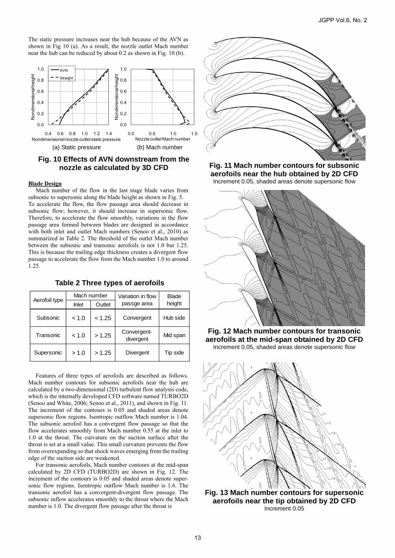
The static pressure increases near the hub because of the AVN as shown in Fig 10 (a). As a result, the nozzle outlet Mach number near the hub can be reduced by about 0.2 as shown in Fig. 10 (b). Blade Design Mach number of the flow in the last stage blade varies from subsonic to supersonic along the blade height as shown in Fig. 5. To accelerate the flow, the flow passage area should decrease in subsonic flow; however, it should increase in supersonic flow. Therefore, to accelerate the flow smoothly, variations in the flow passage area formed between blades are designed in accordance with both inlet and outlet Mach numbers (Senoo et al., 2010) as summarized in Table 2. The threshold of the outlet Mach number between the subsonic and transonic aerofoils is not 1.0 but 1.25. This is because the trailing edge thickness creates a divergent flow passage to accelerate the flow from the Mach number 1.0 to around 1.25. Features of three types of aerofoils are described as follows. Mach number contours for subsonic aerofoils near the hub are calculated by a two-dimensional (2D) turbulent flow analysis code, which is the internally developed CFD software named TURBO2D (Senoo and White, 2006; Senoo et al., 2011), and shown in Fig. 11. The increment of the contours is 0.05 and shaded areas denote supersonic flow regions. Isentropic outflow Mach number is 1.04. The subsonic aerofoil has a convergent flow passage so that the flow accelerates smoothly from Mach number 0.55 at the inlet to 1.0 at the throat. The curvature on the suction surface after the throat is set at a small value. This small curvature prevents the flow from overexpanding so that shock waves emerging from the trailing edge of the suction side are weakened. For transonic aerofoils, Mach number contours at the mid-span calculated by 2D CFD (TURBO2D) are shown in Fig. 12. The increment of the contours is 0.05 and shaded areas denote super-sonic flow regions. Isentropic outflow Mach number is 1.6. The transonic aerofoil has a convergent-divergent flow passage. The subsonic inflow accelerates smoothly to the throat where the Mach number is 1.0. The divergent flow passage after the throat is
(a) Static pressure (b) Mach number
Fig. 10 Effects of AVN downstream from the nozzle as calculated by 3D CFD
0.0
0.2
0.4
0.6
0.8
1.0
0.0 0.5 1.0 1.5
Non
dim
ensio
nal h
eigh
t
Nozzle outlet Mach number
0.0
0.2
0.4
0.6
0.8
1.0
0.4 0.6 0.8 1.0 1.2 1.4
Non
dim
ensio
nal h
eigh
t
AVN
Straight
Nondimensional nozzle outlet static pressure
Inlet Outlet
Subsonic < 1.0 < 1.25 Convergent Hub side
Transonic < 1.0 > 1.25Convergent-
divergentMid span
Supersonic > 1.0 > 1.25 Divergent Tip side
Mach numberAerofoil type
Variation in flowpassge area
Bladeheight
Table 2 Three types of aerofoils
Fig. 12 Mach number contours for transonic aerofoils at the mid-span obtained by 2D CFD
Increment 0.05, shaded areas denote supersonic flow
Fig. 13 Mach number contours for supersonic aerofoils near the tip obtained by 2D CFD
Increment 0.05
Fig. 11 Mach number contours for subsonic aerofoils near the hub obtained by 2D CFDIncrement 0.05, shaded areas denote supersonic flow
JGPP Vol.6, No. 2
13
designed using the method of characteristics (Senoo et al., 2010), so that the supersonic flow can accelerate to the Mach number 1.6 without generating strong shock waves. For supersonic aerofoils, Mach number contours near the tip calculated by 2D CFD TURBO2D are shown in Fig. 13. The in-crement of the contours is 0.05. Design inflow Mach number is 1.26 and isentropic outflow Mach number is 2.1. To weaken the detached bow shock waves upstream from the aerofoils, the fol-lowing two geometrical features are applied. One is that the thickness of the leading edge gradually increases downstream. The other is that the curvature of the upstream part on the pressure surface is set at almost zero. In addition to that, the divergent flow passage formed between aerofoils makes the supersonic flow ac-celerate smoothly and weakens the shock waves emerging from the trailing edge. As a result, the boundary layer separation, which causes severe energy losses because of the interaction with shock waves, does not occur. The aerodynamic performance of the su-personic aerofoils is validated by cascade wind tunnel tests as described in the next section. CASCADE TEST OF THE SUPERSONIC SECTION As for the supersonic inflow tip section, the aerodynamic per-formance is strongly related to whether its cascade throat is su-personic (started) or not (unstarted). When the cascade throat be-comes unstarted, a detached bow shock wave generates large aer-odynamic losses and reduces mass flow rates through the passage. Hence, the started passage design is more preferable for the su-personic inflow section. In the present study, the blade profile is optimized by using turbulent flow analyses with TURBO2D as mentioned above, so as to make the cascade throat become started. In order to validate the design concept of the supersonic inflow section, cascade tests were carried out in the high speed wind tunnel at Kyushu University, Japan. The wind tunnel is a blow down type, and air is used as working fluid. The achievable stagnation pressure is sufficiently high so as to achieve a high Mach number of 3.5 operating as an ordinary wind tunnel facility. The wind tunnel mainly consists of (i) a settling chamber, (ii) a block-type test section assembly including a supersonic nozzle section, and (iii) a movable diffuser section downstream from the test section. The test section assembly is hydraulically clamped without any tie bolts. Thus, the test section assembly is easily replaced in a short time. The whole test section assembly as shown in Fig. 14 is designed and manufactured so as to match the present test conditions. Design specifications are listed in Table 3. The inlet Mach number is 1.26, and the outlet Mach number is 2.1. Cascade scale
ratio and blade aspect ratio are fundamentally important parameters to determine the blade layout in the test section. The number of blades, mass flow rate and shock wave interaction with the wind tunnel walls are primarily considered to determine those parameter values. The scale ratio is selected as 1/5 of the actual blade, but the Reynolds number based on chord length is able to keep the same order of 106 as the actual one, because of the change in working fluids and operating conditions. To achieve an ideal two-dimensional flow, the blade aspect ratio is selected as more than unity. The cascade consists of seven blades, which are installed into slits manufactured in two sidewall acrylic windows. As the first step of the cascade test, shock patterns were visual-ized by using the Schlieren technique. The test results show the excellent starting characteristic of the wind tunnel, which becomes completely started at the stagnation pressure of 250 kPa (A). Figure 15 shows the result obtained as a Schlieren picture at the design inlet Mach number. Black shaded areas around the aerofoils are caused by strain in the acrylic window in which blades were in-stalled. The strain is generated when the slits on the acrylic window for fixing the aerofoils were machined. SS is an acronym for suc-tion surface and PS is an acronym for pressure surface. Shock waves are sufficiently attached to the blade leading edges, and the cascade passages are found to be started as designed. A distribution of the density gradient magnitude (pseudo-Schlieren picture) in an infinite periodic cascade calculated by TURBO2D is shown in Fig. 16 and that in a wind tunnel configuration calculated by the commercial CFD code, ANSYS CFX11®, is shown in Fig. 17. These results show excellent agreement regarding impinging positions and propagating angles of shock waves including de-tached bow shock waves in front of the leading edges, oblique shock waves emerging from the trailing edge, and their reflection waves on the blade surface. Therefore the turbulent flow analysis is validated in a qualitative sense. No boundary layer separation caused by interactions with shock waves is observed. In addition, unstarting problems never occur. Therefore the excellent performance of the supersonic turbine aerofoils is verified. RELIABLITY Mechanical Strength
The titanium 3600rpm-50inch and 3000rpm-60inch last stage blades were developed which satisfied the design criteria regarding such items as ductile strength under centrifugal force, vibratory strength, high cycle and low cycle fatigue strengths under corrosive environments, and having a solid connection at tip covers and mid-span tie-bosses. Light weight and high rigidity are crucial concepts of blade profile design because the former contributes to low stress at the blade root attachments and the latter reduces the risk of buffeting stress and plastic deformation. In order to evaluate the static strength of the blade profile and root attachments, three dimensional non-linear finite element analyses were performed
Convergent-divergent nozzle
Supersonic cascade
Upper tailboard support
Fig. 14 Supersonic cascade test section assembly
Table 3 Design specifications of the supersonic cascade
Parameter Unit Value
Stagnation pressure kPa (A) 250
Stagnation temperature K 280
Inlet Mach number - 1.26
Outlet Mach number - 2.1
Scale ratio - 1/5
Reynolds number, Rec,2 - 2.3×10⁶
Blade aspect ratio - 1.07
Number of blades - 7
Working fluid - Air
JGPP Vol.6, No. 2
14
considering large deformation and contact behavior at the cover, tie-boss, and blade root attachments. The stress distributions by centrifugal force and steam force are shown in Fig. 18. Residual deformation after the 120 % over-speed test was also examined by elasto-plastic analysis and a solid connection is confirmed at the contact surfaces of the cover and tie-boss under the supposed scatter of clearances and manufacturing tolerance. High cycle fatigue strength was evaluated at local stress concentration area by dynamic stress analysis and corrosion fatigue tests of blade and rotor materials.
To get the ideal structure of the cover and tie-boss realizing high damping and low fretting wear, contact force ratio, which is
the ratio of vibration tangential force to the centrifugal normal force, was optimized by changing the contact angle, clearance and contact area. In designing the blade root attachments where the highest local stress occurs, peak stress was minimized using in-house design tools under the conditions satisfying the static stress criteria of cross-sectional stress and contact pressure. Low cycle and high cycle fatigue strengths at blade-root attachments were confirmed by mock-up tests modeling the root attachment structure considering the reduction of strength by fretting fatigue at the contact edge and the surface roughness. As to stress corrosion cracking), it is noted that titanium blades have a great advantage compared to steel blades because titanium is less susceptible to stress corrosion cracking and the titanium lighter weight profile leads to low stress at the rotor stress concentration area. Vibration The fundamental vibration characteristics of the continu-ously coupled blade structures are characterized by the nodal di-ameter modes shown in Fig.19. When the natural frequency and the number of nodal diameters of the vibration mode coincide with the engine order frequency, blade structures are in resonance and the dynamic response becomes extremely large. Therefore, in the vibration design, resonances of the vibration modes are detuned from the low engine order excitation at and near the rated operation speed. Consequently, it is important to predict the natural frequen-cies of the blade accurately. For this, accurate vibration analysis is applied with extensive modelling, in which contact conditions such as contact region and stiffness at the cover and tie-boss are con-sidered. The cover and tie-boss configurations, tie-boss installed height, and the number of blades and so on were investigated using Fig. 19 Three-nodal-diameter mode
Nodaldiameter
line
1st bending mode
Fig. 18 Centrifugal stress distribution state
High
Low
Concave side Convex side
Steam inlet
Test window
Fig. 17 CFD results as a Schlieren picture in the wind tunnel configuration
Fig. 15 Test results as a Schlieren picture
SS
PS
Upper tailboard
SS: suction surface PS: pressure surface
Fig. 16 TURBO2D results as a pseudo- Schlieren picture in an infinite periodic
cascade
JGPP Vol.6, No. 2
15
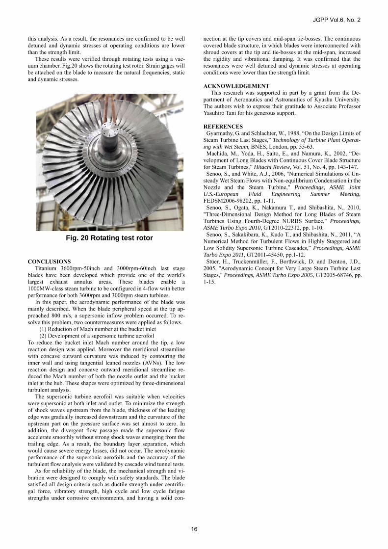
this analysis. As a result, the resonances are confirmed to be well detuned and dynamic stresses at operating conditions are lower than the strength limit. These results were verified through rotating tests using a vac-uum chamber. Fig.20 shows the rotating test rotor. Strain gages will be attached on the blade to measure the natural frequencies, static and dynamic stresses. CONCLUSIONS Titanium 3600rpm-50inch and 3000rpm-60inch last stage blades have been developed which provide one of the world’s largest exhaust annulus areas. These blades enable a 1000MW-class steam turbine to be configured in 4-flow with better performance for both 3600rpm and 3000rpm steam turbines. In this paper, the aerodynamic performance of the blade was mainly described. When the blade peripheral speed at the tip ap-proached 800 m/s, a supersonic inflow problem occurred. To re-solve this problem, two countermeasures were applied as follows. (1) Reduction of Mach number at the bucket inlet (2) Development of a supersonic turbine aerofoil To reduce the bucket inlet Mach number around the tip, a low reaction design was applied. Moreover the meridional streamline with concave outward curvature was induced by contouring the inner wall and using tangential leaned nozzles (AVNs). The low reaction design and concave outward meridional streamline re-duced the Mach number of both the nozzle outlet and the bucket inlet at the hub. These shapes were optimized by three-dimensional turbulent analysis. The supersonic turbine aerofoil was suitable when velocities were supersonic at both inlet and outlet. To minimize the strength of shock waves upstream from the blade, thickness of the leading edge was gradually increased downstream and the curvature of the upstream part on the pressure surface was set almost to zero. In addition, the divergent flow passage made the supersonic flow accelerate smoothly without strong shock waves emerging from the trailing edge. As a result, the boundary layer separation, which would cause severe energy losses, did not occur. The aerodynamic performance of the supersonic aerofoils and the accuracy of the turbulent flow analysis were validated by cascade wind tunnel tests. As for reliability of the blade, the mechanical strength and vi-bration were designed to comply with safety standards. The blade satisfied all design criteria such as ductile strength under centrifu-gal force, vibratory strength, high cycle and low cycle fatigue strengths under corrosive environments, and having a solid con-
nection at the tip covers and mid-span tie-bosses. The continuous covered blade structure, in which blades were interconnected with shroud covers at the tip and tie-bosses at the mid-span, increased the rigidity and vibrational damping. It was confirmed that the resonances were well detuned and dynamic stresses at operating conditions were lower than the strength limit. ACKNOWLEDGEMENT This research was supported in part by a grant from the De-partment of Aeronautics and Astronautics of Kyushu University. The authors wish to express their gratitude to Associate Professor Yasuhiro Tani for his generous support. REFERENCES Gyarmathy, G. and Schlachter, W., 1988, “On the Design Limits of
Steam Turbine Last Stages,” Technology of Turbine Plant Operat-ing with Wet Steam, BNES, London, pp. 55-63.
Machida, M., Yoda, H., Saito, E., and Namura, K., 2002, “De-velopment of Long Blades with Continuous Cover Blade Structure for Steam Turbines,” Hitachi Review, Vol. 51, No. 4, pp. 143-147. Senoo, S., and White, A.J., 2006, "Numerical Simulations of Un-
steady Wet Steam Flows with Non-equilibrium Condensation in the Nozzle and the Steam Turbine," Proceedings, ASME Joint U.S.-European Fluid Engineering Summer Meeting, FEDSM2006-98202, pp. 1-11. Senoo, S., Ogata, K., Nakamura T., and Shibashita, N., 2010,
"Three-Dimensional Design Method for Long Blades of Steam Turbines Using Fourth-Degree NURBS Surface," Proceedings, ASME Turbo Expo 2010, GT2010-22312, pp. 1-10.
Senoo, S., Sakakibara, K., Kudo T., and Shibashita, N., 2011, “A Numerical Method for Turbulent Flows in Highly Staggered and Low Solidity Supersonic Turbine Cascades,” Proceedings, ASME Turbo Expo 2011, GT2011-45450, pp.1-12.
Stüer, H., Truckenmüller, F., Borthwick, D. and Denton, J.D., 2005, "Aerodynamic Concept for Very Large Steam Turbine Last Stages," Proceedings, ASME Turbo Expo 2005, GT2005-68746, pp. 1-15.