Development of A Highly Automated System for the Remote Evaluation of Individual Tree Parameters Richard Pollock Abstract.--A highly-automated procedure for remotely estimating individual tree location, crown diameter, species class, and height has been developed. This procedure will involve the use of a multimodal airborne sensing system that consists of a digital frame camera, a scanning laser rangefinder, and a position and orientation measurement system. Data from the multinaodal sensing system will be processed by a model-based procedure for the recognition of individual tree crowns in aerial images. Both the multimodaI sensing and tree crown recognition components have been separately tested, and data to test their integration have recently been acquired as part of an in-progress experiment. The tree crown recognition procedure has been extended to use data from the scanning laser rangefinder to increase the reliability of individual tree crown isolation and to estimate tree height. Depending on Ihe results of the experiment, the integrated system may be useful in many forest inventory activities, delivering data at a low cost relative to its value. The overall objective of this work is to develop a highly natural color digital frame cantata _,and a POMS consist- automated procedure for remotely estimating the location, ing of a global positioning system (GPS) receiver and an vertically projected crown diameter, species class, and inertial measurement unit (IMU). The camera and height of large numbers of individual trees from digital rangefinder sensing head arc attached to a rigid mount image and range data acquired fi'om an aircraft. The (fig. 1) so that their central optical axes are parallel, and procedure is being developed as the integration of a the scanning plane of the rangefinder is parallel to the multimodal airborue sensing system that consists of a rows of the camera detector array. digital frame camera, a scanning laser rangeflnder, and a position and orientation measurement system (POMS), A Kodak DCS420 camera incorporating a 28-nnn lens can with a model-based procedure tbr the recognition of acquire sharp aerial images with an approximately 20-era individual tree crowns in aerial images. Both the ground projected pixel dimension and an approximately multimodal sensing system and the tree crown recognition 310- by 207-m ground footprint at a 85- to 90-mph procedure have been separately tested. Data (including ground speed and at 620 m above ground level under most reference data) have recently been acquired for testing the daylight illumination conditions. This camera configura- integrated system, tion has a 28-degree long-axis field of view, which is close to the ALTM 1020 30-degree maximum field of MULTIMODAL SENSING SYSTEM view. The ALTM 1020 can be progrmnmed to acquire spot elevations with an approximately 1-m horizontal The multimodal sensingsystem is designed to simulta- ground spacing under these flyingconditions(daylight neously acquire vertical aerial images and dense spot illumination has no effect on ALTM 1020 performance). elevation data in a manner that allows thespatial rclation- TheKodak DCS420 camera can be programmed to ship between the spot elevations (or the cells in a regular- operate witha fixed shutterspeed and automatic aperture grid digital elevation model created from the spot eleva- adjustment (the settings usedto capturean image are tions) and image locations to be readily determined. This stored inthe image file that is downloaded fi'om the facilitates the determination ofthe height of objects camera). This produces sets of images with close-to- portrayed in the images, and the differential rectification uniform overall tone even when scene illmnination varies (removal of scale variations due to scene elevation variation and camera tilt) of theimages, during a flight. The currently implemented system incorporates an Software controls and records images from the camera Optech Airborne Laser Terrain Mapper (ALTM) 1020 during the flight, and calculates from the POMS data the scanning laser rangefinder system, a Kodak DCS420 position and orientation of the camera at the instant of exposure of each image frame. This software was built at Research Scientist, Advanced Systems Applications, Alberta Research Council, 3_d Floor, 6815 8'h Street NE, : The mention of a specific commercialproduct in this article is Calgary, Alberta, Canada, T2H-7H 7. Voice: (403) 297- solely]br the reader's ir_formationand is" not intended to be an 7558, fax: (403) 297-2339, e-mail: pollock@arc.ab.ca, endorsement of the manuj_teturer'sproduct. 638
Transcript
Development of A Highly Automated System for the Remote Evaluation of Individual Tree Parameters
Richard Pollock
Abstract.--A highly-automated procedure for remotely estimating individual treelocation, crown diameter, species class, and height has been developed. This
procedure will involve the use of a multimodal airborne sensing system that consistsof a digital frame camera, a scanning laser rangefinder, and a position and orientationmeasurement system. Data from the multinaodal sensing system will be processed
by a model-based procedure for the recognition of individual tree crowns in aerialimages. Both the multimodaI sensing and tree crown recognition components havebeen separately tested, and data to test their integration have recently been acquired
as part of an in-progress experiment. The tree crown recognition procedure has beenextended to use data from the scanning laser rangefinder to increase the reliability ofindividual tree crown isolation and to estimate tree height. Depending on Ihe results
of the experiment, the integrated system may be useful in many forest inventoryactivities, delivering data at a low cost relative to its value.
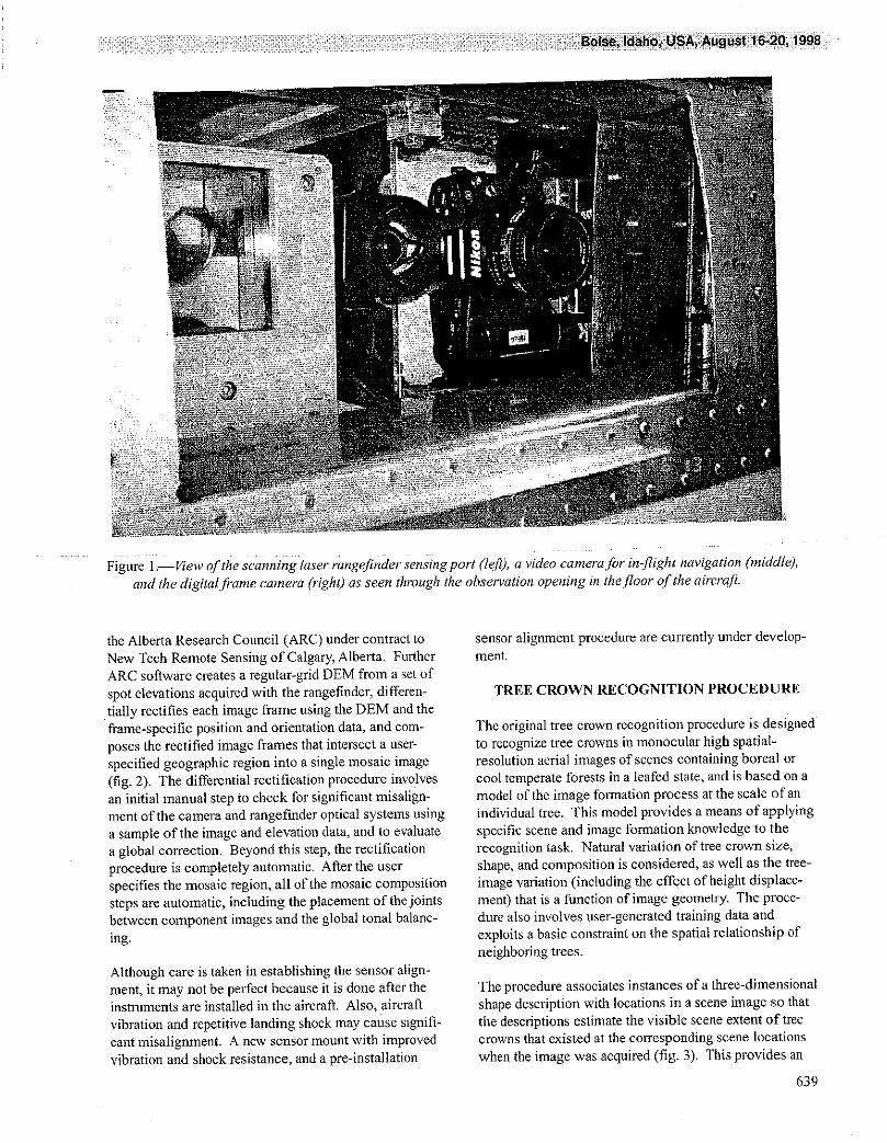
The overall objective of this work is to develop a highly natural color digital frame cantata _,and a POMS consist-automated procedure for remotely estimating the location, ing of a global positioning system (GPS) receiver and anvertically projected crown diameter, species class, and inertial measurement unit (IMU). The camera andheight of large numbers of individual trees from digital rangefinder sensing head arc attached to a rigid mountimage and range data acquired fi'om an aircraft. The (fig. 1) so that their central optical axes are parallel, andprocedure is being developed as the integration of a the scanning plane of the rangefinder is parallel to themultimodal airborue sensing system that consists of a rows of the camera detector array.digital frame camera, a scanning laser rangeflnder, and aposition and orientation measurement system (POMS), A Kodak DCS420 camera incorporating a 28-nnn lens canwith a model-based procedure tbr the recognition of acquire sharp aerial images with an approximately 20-eraindividual tree crowns in aerial images. Both the ground projected pixel dimension and an approximatelymultimodal sensing system and the tree crown recognition 310- by 207-m ground footprint at a 85- to 90-mphprocedure have been separately tested. Data (including ground speed and at 620 m above ground level under mostreference data) have recently been acquired for testing the daylight illumination conditions. This camera configura-integrated system, tion has a 28-degree long-axis field of view, which is
close to the ALTM 1020 30-degree maximum field ofMULTIMODAL SENSING SYSTEM view. The ALTM 1020 can be progrmnmed to acquire
spot elevations with an approximately 1-m horizontalThe multimodal sensing system is designed to simulta- ground spacing under these flying conditions (daylightneously acquire vertical aerial images and dense spot illumination has no effect on ALTM 1020 performance).elevation data in a manner that allows the spatial rclation- The Kodak DCS420 camera can be programmed to
ship between the spot elevations (or the cells in a regular- operate with a fixed shutter speed and automatic aperturegrid digital elevation model created from the spot eleva- adjustment (the settings used to capture an image aretions) and image locations to be readily determined. This stored in the image file that is downloaded fi'om thefacilitates the determination of the height of objects camera). This produces sets of images with close-to-portrayed in the images, and the differential rectification uniform overall tone even when scene illmnination varies(removal of scale variations due to scene elevationvariation and camera tilt) of the images, during a flight.
The currently implemented system incorporates an Software controls and records images from the cameraOptech Airborne Laser Terrain Mapper (ALTM) 1020 during the flight, and calculates from the POMS data thescanning laser rangefinder system, a Kodak DCS420 position and orientation of the camera at the instant of
exposure of each image frame. This software was built at
Research Scientist, Advanced Systems Applications,Alberta Research Council, 3_dFloor, 6815 8'h Street NE, :The mention of a specific commercialproduct in this article is
Calgary, Alberta, Canada, T2H-7H 7. Voice: (403) 297- solely]br the reader's ir_formationand is"not intended to be an7558, fax: (403) 297-2339, e-mail: [email protected], endorsement of the manuj_teturer'sproduct.
638
Figure l.--V/ew of the scanning laser rangeftnder sensing port (left), a video camera for in-fight navigation (middle),and the digital frame camera O'ight) as seen thlvugh the obselwation opening in the floor of the aircraft.
the Alberta Research Council (ARC) under contract to sensor alignment procedure are currently under develop-New Tech Remote Sensing of Calgary, Alberta. Further ment.ARC software creates a regular-grid DEM from a set of
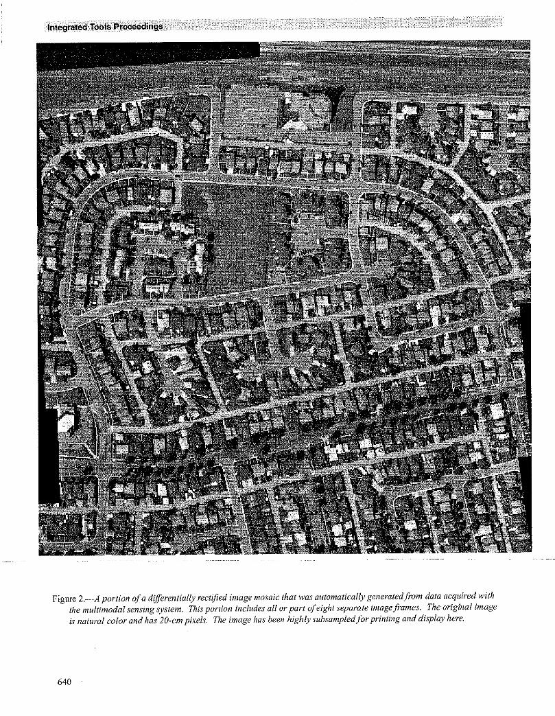
spot elevations acquired with the rangefinder, differen- TREE CROWN RECOGNITION PROCEDUREtially rectifies each image frame using the DEM and theframe-specific position and orientation data, and corn- The original tree crown recognition procedure is designed
poses the rectified image frames that intersect a user- to recognize tree crowns in monocular high spatial-specified geographic region into a single mosaic image resolution aerial images of scenes containing boreal or(fig. 2). The differential rectification procedure involves cool temperate forests in a leafed state, and is based on aan initial manual step to check for significant misalign- model of the image formation process at the scale of anment of the camera and rangefinder optical systems using individual tree. This model provides a means of applying
a sample of the image and elevation data, and to evaluate specific scene and image formation knowledge to thea global correction. Beyond this step, the rectification recognition task. Natural variation of tree crown size,
procedure is completely automatic. Afier the user shape, and composition is considered, as well as the tree-specifies the mosaic region, all uftbe mosaic composition image variation (including the effect of height displace-steps are automatic, including the placement of the joints ment) that is a function of image geometry. The proce-between component images and the global tonal balanc- dure also involves user-generated training data and
ing. exploits a basic constraint on the spatial relationship ofneighboring trees.
Although care is taken in establishing the sensor a[ign-ment, it may not be perfect because it is done after the The procedure associates instances of a three-dimensionalinstruments are installed in the aircraft. Also, aircraft shape description with locations in a scene image so that
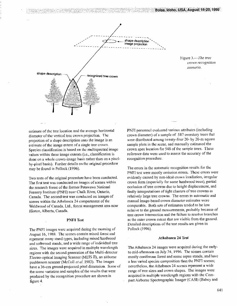
vibration and repetitive landing shock may cause signifi- the descriptions estimate the visible scene extent of treecant misalignment. A new sensor mount with improved crowns that existed at the corresponding scene locationsvibration and shock resistance, and a pre-installation when the image was acquired (fig. 3). This provides an
639
Figure 2.--A portion of a dif]krentially rectified image mosaic that was automatically generated from data acquired withthe multimodal sensing system. This portion includes ull or part of eight separate image frames. The original imageis natural color and has 20-cm pixels. The image has been highly subsampled for printing and display here.
640
.'" _ shapedescription'-.._ wnageprojection -•
Figure 3. -]'he treecrown i'ecogn[t[on
seena/'io.
shapedescri3fOWl3
estimate of the tree location and the average horizontal PNFI personnel evahmted various attributes (includingdiameter of the vertical tree crown projection. The crown diameter) of a sample of 587 overstory trees thatprojection of a shape description onto the image is an were distributed among twenty-f bur 20- by 20-m squareestimate of the image extent of a single tree crown, sample plots in the scene, and manually estimated the
Species classification is based on the multispectral image crown apex location for 548 of the sample trees. Thesevalues within these image extents (i.e., classification is reference data were used to assess the accuracy of thedone on a whole crown-image basis rather than on a pixel- recognition proeednre.
by-pixel basis). Further details on the original proceduremay be found in Pollock (1996). The errors in the automatic recognition results for the
PNFI test were mostly omission errors. These errors wereTwo tests of the original procedure have been conducted, evidently caused by non-ideal crown irradiation, irregularThe first test was conducted on images of scenes within crown form (especially for some hardwood trees), partialthe research forest of the former Petawawa National occlusion of tree crowns due to height displacement, andForestry institute (PNFI) near Chalk River, Ontario, faulty interpretations of tight clusters of tree Crowns asCanada. The second test was conducted on images of relatively large tree crowns. The errors in automatic andscenes within the Athabasca 24 eompamnent of the manual image-based crown diameter estimates wereWeldwood of Canada, Ltd., forest management area near comparable. Both sets of estimates tended to be lowHinton, Alberta, Canada. relative to the ground measurements, probably because of
tree crown intersection and the failure to resolve branches
PNFI Test at the outer crown extent that are visible from the ground.Detailed descriptions of the test results are given in
The PNFI images were acquired during the morning of Pollock (1996).August 16, 1988. The scenes contain mixed forest andrepresent many stand types, including mixed hardwood Athabasea 24 Testand softwood stands, and a wide range of individual treesizes. The images were acquired in multiple wavelength The Athabasca 24 images were acquired during the early-regions with the second generation of the Multi-detector to mid-afternoon on July 24, 1996. The scenes containElectro-optical Imaging Scanner (MEIS II), an airborne mostly coniferous forest and some aspen stands, and havepushbroom scanner (McColl et al. 1983). The images a less varied species composition than the PNFI scenes;have a 36-cm ground-projected pixel dimension. Some of nevertheless, the Athabasea 24 scenes represent a widethe scene variation and samples &the results that were range of tree sizes and crown shapes. The images were
produced by the recognition procedure are shown in acquired in multiple wavelength regions with the Corn-figure 4. pact Airborne Spectrographic Imager (CAS1) (Babey and
641
Figure 4. 5'ubimagesji'om theimage d_lta and automaticindividual tree crown
recognition results for l-haPNFI subscenes. The
subimages were extractedfrom the visible greenwavelength channel of thetest image data. The imagep:'q/eczio:_ of the shapedescription boundary foreach of the recognizedetvwns is superimposed in
5 white on the subimages in_: _i the right column. The
_: boundary q/'a 20- by 20-m'_: glvund sample plot is
superimposed in white onall subimages.
Anger 1989). The images were acquired with a 60-era resolution of the image data and the amount of aliasingground-projected instantaneous field of view, and present were very likely significant obstacles to bothresampled to a 50-era pixel dimension during rectifica- manual and automatic tree crown recognition. Field visitstion. Some of the scene variation and samples of the confirmed that many relatively small trees of merchant-results that were produced by the recognition procedure able size could not be manually resolved in the imageare shown in figure 5. The results show that the recogni- data. Because of this, only a superficial assessment of thetion procedure is largely able to accormnodate the results (relative to the PNFI test) was conducted. Fundsvariation represented by the scene, that were to be spent on more intensive fieldwork in
Athabasca 24 have been diverted to the assessment of the
Early in the examination of the Athabasca 24 image data results from the test of the current integrated system.and the recognition results, we concluded that the spatial
642
i :
Figure 5._ubimages ji'om_ _ the image data and
aulomatie #ee crown
recognition results./br 1-
_._.._.,_ ha Athabasca24
___ _ subimages were extracted_. .firm the visible green
' wavelength channel of
the image data. Theimage projection of theshape descriptionboundarv fi)r each c_therecognized crowns issuperimposed in white onthe subz?nages in theright cohomt.
A comparison of the recognition results within six l-ha crowns and were often either missed altogether (i.e.,scene regions with on-foot field observations revealed the interpreted as ground vegetation) or were inteFpreted as afollowing common errors: (1) trees with a crown diam- group of relatively few trees. These errors usually couldeter of less that 1 m were often missed, even when they not be recognized through manna/interpretation of t_egrew in uncrowded conditions; (2) tight groups of small image data alone.trees were often automatically recognized as a single tree;(3) where crowns were relatively close togethel, shorter The field observations revealed that near-infiared/red/and smaller crowns were often missed; (4) forked trees green false-color composites of the Athabasca 24 datawere usually recognized as single crowns; and (5) contain color-distinctions between different coniferous
members of tight groups of aspen have highly irregular species (lodgepole pine, white spruce, tamarack) and very
643
obvious color distinctions between coniferous species and passes for estimating tree height, newer models of the
aspen, at least where individual tree crowns are easily ALTM have this capability.recognized. An automatic supervised classification of treecrown image regions based on multispectral image values We have shown that the spatial registration of spotwithin the direct irradiation portions of these regions elevations and image data from the multimodal sensing
yielded results that were consistent with manual interpre- system is at a submeter accuracy. Therefore, we expecttation results, that tree crown recognition results could be used to
automatically select first-pulse spot elevations that
Summary coincide most closely with the tops of tree crowns (asopposed to the margin of the crowns or to between-crown
The PNFI and Athabasea 24 tests of the original recogni- gaps), and last-pulse spot elevations fi'om pulses that have
tion procedure strongly suggest that improved spatial traveled between tree crowns on their way to the ground.resolution is required for the procedure to produce tree Software that perfmxns this type of spot-elevationrecognition results that would be generally accepted i-br selection has been built at ARC. In addition, the treeuse in forestry. The tests also indicate that greater crown recognition software has been extended so that itaccommodation of the effects of crowding on tree crown will use local elevation minima in a top-of-canopyimages (irregular crown form and lighting) is required, elevation model as an additional cue for separating
Color-infrared image data provide a basis for a useful crowded tree crowns that may have irregular fonn andspecies classification. The procedure does not address the lighting.estimation of tree height, which is a significant omissionbecause tree height is highly valuable for tile esthrration of 1N-PROGRESS EXPERIMENTtimber volume.
The in-progress experiment is designed to answer theINTEGRATION following questions:
Kodak DCS420 three-color aerial images with a 20-cm I. How accurate is the georeferencing of the data from
ground-projected pixel dimension allow better manual the multimodal sensing system?resolution of small trees than do the MEIS 11and CASI 2. How well does the ALTM 1020 determine ground
images involved in experiments described earlier (both of elevation through different types of forest canopy?these data sets were acquired at the finest spatial-resolu- 3. How accurately can tree height be estimated with thetion possible at the time with a standard twin-engine integrated system?aircraft platform). This is significant with respect to the 4. Can top-of-canopy elevations be used to improve thefindings of the Athabasca 24 experiment described above, separation of crowded tree crowns?Also, the Kodak DCS cameras are available in green-red-
nir (color infrared) versions, which is significant with Data were acquired with the multimodal sensing systemrespect to tree species classification, on July 25, 1998 for a 5- by 10-km site near Manning,
AB, Canada. This site contains a variety of boreal forest
The ALTM 1020 can be programmed to determine range stands. Markers that are visible in the aerial images have
aecording to either the first or the last pulse in the return been placed over 26 points distributed throughout the sitepulse-train associated with an outgoing laser pulse whose locations have been determined to 3 cm accuracy(commonly referred to as operating in, respectively, "first with GPS; these data will be used to answer the firstpulse" or"last pulse" mode). In principle, the ALTM question. Dense networks of ground elevations have been1020 produces spot elevations for the top surlhce of a nreasured within a variety of tree stands (e.g., blackforest canopy when operating in first pulse mode, and spruce, white spruce, aspen) using a total station instnl-
produces spot elevations for beneath-canopy terrain when ment; these data will be used to answer the secondoperating in last pulse mode. In fact, a significant return question. Large-scale (1:800) 70 mm fomlat photographspulse may only be returned once the outgoing pulse has have been obtained for 50 plots within the site (tree heightpenetrated some distance into a forest canopy, and a can be manually estimated with a 10 cm accuracy on thetrailing pulse may be returned by a tree tmnk or dense basis of these photographs); these data in combinationundergrowth rather than what may be considered to be the with ground visits will be used to answer the third andground). Data from the ALTM 1020 have a clear-terrain fourth questions.elevation precision of 15 em, so it is reasonable to expectthat such data could be used to estimate tree height to a CONCLUSION
precision within tm.A highly automated system for the remote evaluation of
Although the ALTM 1020 cannot collect first- and last- large mtmbers of individual tree crowns has been built bypulse data simultaneously, which necessitates dual flight integrating a multimodal sensing system with a tree crown
644
recognition procedure, both of which have already been Landscape Management Network at the Pacific Forestrytested. Data have recently been acquired with the Centre of Natural Resources Canada, provided access to
multimodal sensing system for a site in northern Alberta. the MIES II image data and associated reference dataThese data, together with large-scale airphotos and used in this work. Current financial support for theground reference data that have also been collected, will rnultimodal sensing and system integration work isbe used to assess the performance of the integrated provided by the Alberta Research Council and New-Tech
system. Depending on the results of the in-progress Remote Sensing of Calgary, AB, Canada.experiment, the integrated system may be useful in manyforest inventory activities, delivering data at a low cost The following people reviewed this manuscript: Janrelative to its value. This work has also set the stage for Murder, Alberta Research Council, Calgary, AB, Canada,
exploiting improvements in scanning laser rangefinder, and David Stonehouse, New-Tech Remote Sensing,digital camera, and POMS technology. In fact, the Calgary, AB, Canada.equipment that the existing multimodal sensing system isbuilt from is no longer state of the art; now commercially LITERATURE CITEDavailable are digital frame cameras with larger detectorarrays and faster data downloading components and Babey, S.K.; Anger, C.D. 1989. A compact airbornescanning laser rangefinders with a greater sampling rate spectrographic imager (CASI). In: Proceedings ofand simultaneous first- and last-pulse recording capability. IGARSS '89 _ Quantitative remote sensing: and
economic tool for the nineties; 1989 July; Vancouver,ACKNOWLEDGMENTS BC: 1028-1031.
Initial financial support for the tree crown recognition McColl, W.D.; Neville, R.A.; Till, S.M. 1983.work was provided by the Natural Sciences and Engineer- Multidetector electro-optical imaging scanner MEISing Research Council of Canada in the fon_a of a Post- IL In: Proceedings of the 8th Canadian symposiumgraduate Research Fellowship and an Industrial Post- on remote sensing; 1983 May: 71-77.doctoral Research Fellowship to the author, and researchgrants to Robert J. Woodham, Professor and Head, Pollock, Richard. 1996. The automatic recognition ofDepartment of Computer Science, University of British individual trees in aerial images of forests based on aColumbia, and by the Institute for Robotics and Intelli- synthetic tree crown image model. Vancouver, BC:
gent Systems (one of the Canadian Networks of Centers University of British Columbia. 220 p. Ph.D. disserta-&Excellence). Don Leckie, Research Scientist in the tion.