41
SynOptics 28xxx Management Module SPECTRUM Enterprise Manager Device Management Supports Management Module SM-SYN1006 Titlepae Titlepae Titlepae Titlepae
SynOptics 28xxx Management Module
SPECTRUM Enterprise ManagerDevice Management
Supports Management Module SM-SYN1006
TitlepaeTitlepaeTitlepaeTitlepae
S P E C T R U M E n t e r p r i s e M a n a g e r Page 2 S y n O p t i c s 2 8 x x x
NoticeAprisma Management Technologies, Inc. (Aprisma), reserves the right to makechanges in specifications and other information contained in this document withoutprior notice. The reader should in all cases consult Aprisma to determine whetherany such changes have been made.
The hardware, firmware, or software described in this manual is subject to changewithout notice.
IN NO EVENT SHALL APRISMA, ITS EMPLOYEES, OFFICERS, DIRECTORS,AGENTS, OR AFFILIATES BE LIABLE FOR ANY INCIDENTAL, INDIRECT,SPECIAL, OR CONSEQUENTIAL DAMAGES WHATSOEVER (INCLUDING BUTNOT LIMITED TO LOST PROFITS) ARISING OUT OF OR RELATED TO THISMANUAL OR THE INFORMATION CONTAINED IN IT, EVEN IF APRISMA HASBEEN ADVISED OF, KNOWN, OR SHOULD HAVE KNOWN, THE POSSIBILITYOF SUCH DAMAGES.
Copyright © October 2000 by Aprisma Management Technologies. All rightsreserved.
Printed in the United States of America.
Order Number: 9032252-01
Aprisma Management Technologies, Inc.121 Technology DriveDurham NH 03824
SPECTRUM, the SPECTRUM IMT/VNM logo, DCM, IMT, and VNM are registeredtrademarks, and SpectroGRAPH , SpectroSERVER , Inductive ModelingTechnology , Device Communications Manager , and Virtual Network Machineare trademarks of Aprisma or its affiliates.
Ethernet is a trademark of Xerox Corporation.
Virus DisclaimerAprisma makes no representations or warranties to the effect that the LicensedSoftware is virus-free.
Aprisma has tested its software with current virus checking technologies. However,because no anti-virus system is 100% reliable, we strongly caution you to writeprotect and then verify that the Licensed Software, prior to installing it, is virus-freewith an anti-virus system in which you have confidence.
Restricted Rights Notice(Applicable to licenses to the United States Government only.)
1. Use, duplication, or disclosure by the Government is subject to restrictions asset forth in subparagraph (c) (1) (ii) of the Rights in Technical Data andComputer Software clause at DFARS 252.227-7013.
Aprisma Management Technologies, Inc., 121 Technology Drive NH 03824
2. (a) This computer software is submitted with restricted rights. It may not beused, reproduced, or disclosed by the Government except as provided inparagraph (b) of this Notice or as otherwise expressly stated in the contract.
(b) This computer software may be:
(1) Used or copied for use in or with the computer or computers for whichit was acquired, including use at any Government installation to whichsuch computer or computers may be transferred;
(2) Used or copied for use in a backup computer if any computer for whichit was acquired is inoperative;
(3) Reproduced for archival or backup purposes;
(4) Modified, adapted, or combined with other computer software, providedthat the modified, combined, or adapted portions of the derivativesoftware incorporating restricted computer software are made subjectto the same restricted rights;
(5) Disclosed to and reproduced for use by support service contractors inaccordance with subparagraphs (b) (1) through (4) of this clause,provided the Government makes such disclosure or reproductionsubject to these restricted rights; and
(6) Used or copied for use in or transferred to a replacement computer.
(c) Notwithstanding the foregoing, if this computer software is publishedcopyrighted computer software, it is licensed to the Government, withoutdisclosure prohibitions, with the minimum rights set forth in paragraph (b) ofthis clause.
(d) Any other rights or limitations regarding the use, duplication, or disclosureof this computer software are to be expressly stated in, or incorporated in,the contract.
(e) This Notice shall be marked on any reproduction of this computer software, inwhole or in part.
S P E C T R U M E n t e r p r i s e M a n a g e r Page 3 S y n O p t i c s 2 8 x x x
ContentsINTRODUCTION 5
Purpose and Scope ........................................................5Required Reading ...........................................................5Supported Devices..........................................................6The SPECTRUM Model ..................................................6
Accessing SPECTRUM Views from the Device Icon ..6
DEVICE VIEW 8
Logical Device View........................................................8Logical Module Icon.....................................................9Icon Subviews for the Logical Module .......................10Icon Subviews for Ports.............................................11Switch Community View ............................................11
Port Statistics .........................................................12Network-to-Internal Stats....................................12Network Received ..............................................12Internal Transmit ................................................12Internal-to-Network Stats....................................13Internal Received ...............................................13
Enable/Disable Port ...............................................13Physical Device View....................................................14
CONFIGURATION VIEWS 15
Port Configurations Table..........................................15Chassis Configuration View.......................................21Agent Configuration View ..........................................23
Off-Page Reference Panel ........................................24
APPLICATION VIEWS 26
Application Icons...........................................................27Supported Applications .................................................27SynOptics 28xxx Common Application .........................28
Agent Information View .............................................28Agent Configuration View ......................................28Trap Receiver View ...............................................28
Trap Receiver Table...........................................28Add Trap Receiver View ........................................29
Switch Community View............................................30Domain ..................................................................30
Domain Table.....................................................30Domain Port Table .............................................32Domain Creation View........................................33Port Domain Table .............................................33Standard Table Buttons......................................34
Trunk Information View..........................................34Trunk Information Table .....................................35
Switch List View.....................................................35Switch List Table ................................................35
History Logs ..............................................................36Reset History .........................................................36Error History...........................................................36
Error Log Table ..................................................37
C o n t e n t s C o n t e n t s
S P E C T R U M E n t e r p r i s e M a n a g e r Page 4 S y n O p t i c s 2 8 x x x
Trace History..........................................................37Trace Log Table .................................................37
Sy28xEnSwchApp ........................................................38Port Configurations Table..........................................38Port to MAC View ......................................................38
MODEL INFORMATION VIEWS 39
INDEX 40
S P E C T R U M E n t e r p r i s e M a n a g e r Page 5 S y n O p t i c s 2 8 x x x
Introduction
This section introduces the SPECTRUM Device Management documentation for SynOptics 28xxx Seriesdevices.
This introduction to the SynOptics 28xxx documentation contains the following information:
• Purpose and Scope• Required Reading• The SPECTRUM Model (Page 6)• Supported Devices (Page 6)
Purpose and ScopeUse this documentation as a guide for managing SynOptics devices with the SPECTRUM management module SM-SYN1006. The documentation describes the icons, menus, and views that enable you to remotely monitor, configure, and troubleshoot SynOptics devices through software models in your SPECTRUM database.
Only information specific to the supported management module is included under this topic. For general information about device management using SPECTRUM and for explanation of basic SPECTRUM functionality, and navigation techniques, refer to the documentation listed under Required Reading.
Required ReadingTo use this documentation effectively, you must be familiar with the information covered by the other SPECTRUM online documentation topics listed below.
• Getting Started with SPECTRUM for Operators• Getting Started with SPECTRUM for
Administrators• How to Manage Your Network with SPECTRUM• SPECTRUM Views• SPECTRUM Menus• SPECTRUM Icons
I n t r o d u c t i o n S u p p o r t e d D e v i c e s
S P E C T R U M E n t e r p r i s e M a n a g e r Page 6 S y n O p t i c s 2 8 x x x
• Management Module Software Release Notice
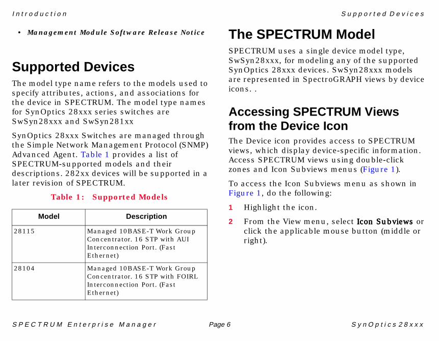
Supported DevicesThe model type name refers to the models used to specify attributes, actions, and associations for the device in SPECTRUM. The model type names for SynOptics 28xxx series switches are SwSyn28xxx and SwSyn281xx
SynOptics 28xxx Switches are managed through the Simple Network Management Protocol (SNMP) Advanced Agent. Table 1 provides a list of SPECTRUM-supported models and their descriptions. 282xx devices will be supported in a later revision of SPECTRUM.
The SPECTRUM ModelSPECTRUM uses a single device model type, SwSyn28xxx, for modeling any of the supported SynOptics 28xxx devices. SwSyn28xxx models are represented in SpectroGRAPH views by device icons. .
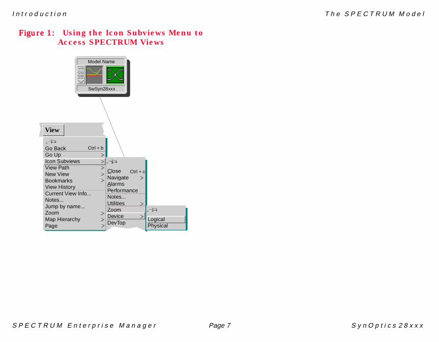
Accessing SPECTRUM Viewsfrom the Device IconThe Device icon provides access to SPECTRUM views, which display device-specific information. Access SPECTRUM views using double-click zones and Icon Subviews menus (Figure 1).
To access the Icon Subviews menu as shown in Figure 1, do the following:
1 Highlight the icon.
2 From the View menu, select Icon SubviewsIcon SubviewsIcon SubviewsIcon Subviews or click the applicable mouse button (middle or right).
Table 1: Supported Models
Model Description
28115 Managed 10BASE-T Work Group Concentrator. 16 STP with AUI Interconnection Port. (Fast Ethernet)
28104 Managed 10BASE-T Work Group Concentrator. 16 STP with FOIRL Interconnection Port. (Fast Ethernet)
I n t r o d u c t i o n T h e S P E C T R U M M o d e l
S P E C T R U M E n t e r p r i s e M a n a g e r Page 7 S y n O p t i c s 2 8 x x x
Figure 1:Figure 1:Figure 1:Figure 1: Using the Icon Subviews Menu to Access SPECTRUM Views
Go BackGo UpIcon SubviewsView PathNew ViewBookmarksView HistoryCurrent View Info...Notes...Jump by name...ZoomMap HierarchyPage
CloseNavigateAlarmsPerformanceNotes...UtilitiesZoomDeviceDevTop
LogicalPhysical
View
Ctrl + b
Ctrl + c
Model Name
SwSyn28xxx
S P E C T R U M E n t e r p r i s e M a n a g e r Page 8 S y n O p t i c s 2 8 x x x
Device View
This section describes the various Device views available for models of SynOptics 28xxx devices inSPECTRUM.
Device views use icons and labels to represent the modeled device and its components such as modules, ports, and applications. There are three types of device views for SynOptics 28000 series switch models:
• Logical Device View• Switch Community View (Page 11)• Physical Device View (Page 14)
SPECTRUM provides both static physical and dynamic logical representations of the switch configuration. With the dynamic logical representation, if the configuration changes, you see the corresponding change within the view after the model’s next polling cycle.
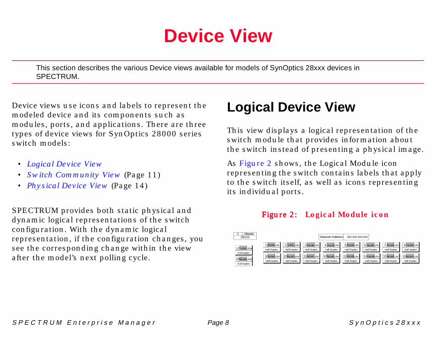
Logical Device View
This view displays a logical representation of the switch module that provides information about the switch instead of presenting a physical image.
As Figure 2 shows, the Logical Module icon representing the switch contains labels that apply to the switch itself, as well as icons representing its individual ports.
Figure 2:Figure 2:Figure 2:Figure 2: Logical Module icon
1 NLNK
Half Duplex
Network Address 1xx.xxx.xxx.xxx
10M
1 Master28115
2 LINK
Half Duplex
10M
10NLNK
Half Duplex
10M9 NLNK
Half Duplex
10M
17 LINK
Full Duplex
200M
18NLNK
Full Duplex
200M11NLNK
Half Duplex
10M
4 NLNK
Half Duplex
10M 5 NLNK
Half Duplex
10M
13 NLNK
Half Duplex
10M12 NLNK
Half Duplex
10M
3 NLNK
Half Duplex
10M 6 NLNK
Half Duplex
10M
14 NLNK
Half Duplex
10M
7 NLNK
Half Duplex
10M
15 NLNK
Half Duplex
10M 16NLNK
Half Duplex
10M
8 NLNK
Half Duplex
10M
D e v i c e V i e w
S P E C T R U M E n t e r p r i s e M a n a g e r Page 9 S y n O p t i c s 2 8 x x x
Logical Module Icon
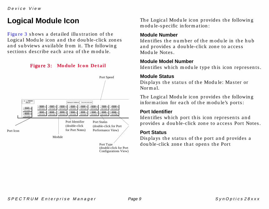
Figure 3 shows a detailed illustration of the Logical Module icon and the double-click zones and subviews available from it. The following sections describe each area of the module.
Figure 3:Figure 3:Figure 3:Figure 3: Module Icon Detail
The Logical Module icon provides the following module-specific information:
Module NumberIdentifies the number of the module in the hub and provides a double-click zone to access Module Notes.
Module Model NumberIdentifies which module type this icon represents.
Module StatusDisplays the status of the Module: Master or Normal.
The Logical Module icon provides the following information for each of the module’s ports:
Port IdentifierIdentifies which port this icon represents and provides a double-click zone to access Port Notes.
Port StatusDisplays the status of the port and provides a double-click zone that opens the Port
Port Icon
Port Status(double-click for PortPerformance View)
Port Identifier(double-clickfor Port Notes)
Module
1 NLNK
Half Duplex
Network Address 1xx.xxx.xxx.xxx
10M
1 Master28115
2 LINK
Half Duplex
10M
10NLNK
Half Duplex
10M9 NLNK
Half Duplex
10M
17LINK
Full Duplex
200M
18NLNK
Full Duplex
200M11NLNK
Half Duplex
10M
4 NLNK
Half Duplex
10M 5 NLNK
Half Duplex
10M
13NLNK
Half Duplex
10M12 NLNK
Half Duplex
10M
3 NLNK
Half Duplex
10M 6 NLNK
Half Duplex
10M
14 NLNK
Half Duplex
10M
7 NLNK
Half Duplex
10M
15NLNK
Half Duplex
10M 16NLNK
Half Duplex
10M
8 NLNK
Half Duplex
10M
Port Type(double-click for PortConfigurations View)
Port Speed
D e v i c e V i e w
S P E C T R U M E n t e r p r i s e M a n a g e r Page 10 S y n O p t i c s 2 8 x x x
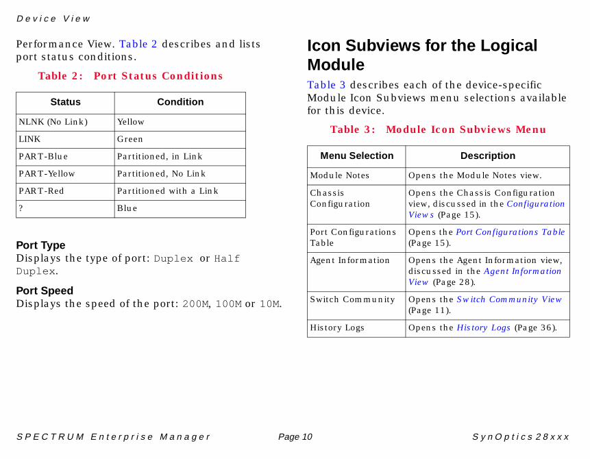
Performance View. Table 2 describes and lists port status conditions.
Port TypeDisplays the type of port: Duplex or HalfDuplex .
Port SpeedDisplays the speed of the port: 200M, 100M or 10M.
Icon Subviews for the LogicalModuleTable 3 describes each of the device-specific Module Icon Subviews menu selections available for this device.
Table 2: Port Status Conditions
Status Condition
NLNK (No Link) Yellow
LINK Green
PART-Blue Partitioned, in Link
PART-Yellow Partitioned, No Link
PART-Red Partitioned with a Link
? Blue
Table 3: Module Icon Subviews Menu
Menu Selection Description
Module Notes Opens the Module Notes view.
Chassis Configuration
Opens the Chassis Configuration view, discussed in the Configuration Views (Page 15).
Port Configurations Table
Opens the Port Configurations Table (Page 15).
Agent Information Opens the Agent Information view, discussed in the Agent Information View (Page 28).
Switch Community Opens the Switch Community View (Page 11).
History Logs Opens the History Logs (Page 36).
D e v i c e V i e w
S P E C T R U M E n t e r p r i s e M a n a g e r Page 11 S y n O p t i c s 2 8 x x x
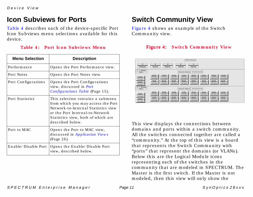
Icon Subviews for PortsTable 4 describes each of the device-specific Port Icon Subviews menu selections available for this device.
Switch Community ViewFigure 4 shows an example of the Switch Community view.
Figure 4:Figure 4:Figure 4:Figure 4: Switch Community View
This view displays the connections between domains and ports within a switch community. All the switches connected together are called a “community.” At the top of this view is a board that represents the Switch Community with “ports” that represent the domains (or VLANs). Below this are the Logical Module icons representing each of the switches in the community that are modeled in SPECTRUM. The Master is the first switch. If the Master is not modeled, then this view will only show the
Table 4: Port Icon Subviews Menu
Menu Selection Description
Performance Opens the Port Performance view.
Port Notes Opens the Port Notes view.
Port Configurations Opens the Port Configurations view, discussed in Port Configurations Table (Page 15).
Port Statistics This selection contains a submenu from which you may access the Port Network-to-Internal Statistics view or the Port Internal-to-Network Statistics view, both of which are described below.
Port to MAC Opens the Port to MAC view, discussed in Application Views (Page 26).
Enable/Disable Port Opens the Enable/Disable Port view, described below.
1 NLNK
Half Duplex
Network Address 1xx.xxx.xxx.xxx
10M
1 Master28xxx
2 LINK
Half Duplex
10M
10NLNK
Half Duplex
10M9 NLNK
Half Duplex
10M
17 LINK
Full Duplex
200M
18NLNK
Full Duplex
200M11NLNK
Half Duplex
10M
4 NLNK
Half Duplex
10M 5 NLNK
Half Duplex
10M
13NLNK
Half Duplex
10M12 NLNK
Half Duplex
10M
3 NLNK
Half Duplex
10M 6 NLNK
Half Duplex
10M
14 NLNK
Half Duplex
10M
7 NLNK
Half Duplex
10M
15 NLNK
Half Duplex
10M 16NLNK
Half Duplex
10M
8 NLNK
Half Duplex
10M
1 NLNK
Half Duplex
Network Address 1xx.xxx.xxx.xxx
10M
1 Normal28xxx
2 NLNK
Half Duplex
10M
10NLNK
Half Duplex
10M9 NLNK
Half Duplex
10M
17 LINK
Full Duplex
200M
18NLNK
Full Duplex
200M11NLNK
Half Duplex
10M
4 NLNK
Half Duplex
10M 5 NLNK
Half Duplex
10M
13NLNK
Half Duplex
10M12 NLNK
Half Duplex
10M
3 NLNK
Half Duplex
10M 6 NLNK
Half Duplex
10M
14 NLNK
Half Duplex
10M
7 NLNK
Half Duplex
10M
15 NLNK
Half Duplex
10M 16NLNK
Half Duplex
10M
8 NLNK
Half Duplex
10M
Switch Community
2Default
#Name
#Name
# #NameName
D e v i c e V i e w
S P E C T R U M E n t e r p r i s e M a n a g e r Page 12 S y n O p t i c s 2 8 x x x
domains that the switch is in and the Logical Module icon for the switch from which the view was accessed. The view will update if a switch or VLAN is added or removed from the community.
Clicking a port number highlights the domain number of the domain icon containing that port. Clicking the domain number on a domain icon highlights the port number of all the ports in the domain. Clicking the domain number again deselects all the ports and the domain icon.
In addition to the capabilities described above, the port and module icons provide the same information described under Logical Module Icon.
Port StatisticsContains a submenu from which the Network-to-Internal Stats and Internal-to-Network Stats views may be accessed.
Network-to-Internal StatsThe SynOptics 28xxx Port Network-to-Internal Statistics View. This view contains the following information:
Network ReceivedThis panel contains the following fields:
Good FramesThe number (32 bit) of good frames received from the network.
Align ErrorsThe number (32 bit) of received frames with an alignment error from the network.
Crc ErrorsThe number (32 bit) of received frames with a CRC error from the network.
OverrunsThe number (32 bit) of times that a receiver overrun condition was detected when receiving frames from the network.
Internal TransmitThis panel contains the following fields:
FramesThe number (32 bit) of transmitted frames to the internal channel.
Note:Note:
The trunk port is not part of the domain: it connects the switches within the LAN. Trunk port icons look the same as port icons in the Switch Community View, except a trunk port icon has a violet background behind its number.
D e v i c e V i e w
S P E C T R U M E n t e r p r i s e M a n a g e r Page 13 S y n O p t i c s 2 8 x x x
Buffer OverflowsDisplays the number (32 bit) of buffer overflows occurring while transmitting a frame to the internal channel.
Internal-to-Network StatsOpens the SynOptics 28xxx Port Internal-to-Network Statistics View. This view contains the following information:
Internal ReceivedThis panel contains the following fields:
FramesThe number (32 bit) of transmitted frames from the internal channel out the port.
Buffer OverflowsThe number (32 bit) of buffer overflows occurring while transmitting a frame from the internal channel out the port.
Network TransmitThis panel contains the following field:
CongestionThe number (32 bit) of times that a congestion was detected when transmitting to the network. The meaning of “congestion” varies between the two types of ports.
Enable/Disable PortThis panel lets you enable or disable a particular port. The port state is displayed along with the following fields and buttons:
ModuleThe number specifying the hub location of the module containing the port.
PortThe number uniquely identifying the selected port on the module.
Port StateThis menu button allows you to EnableEnableEnableEnable or DisableDisableDisableDisable the port.
Applies the current settings.
Reads and updates the information from the device.
Use this button to exit the view. Unapplied settings will revert to last applied settings.
Apply
Read
Cancel
D e v i c e V i e w P h y s i c a l D e v i c e V i e w
S P E C T R U M E n t e r p r i s e M a n a g e r Page 14 S y n O p t i c s 2 8 x x x
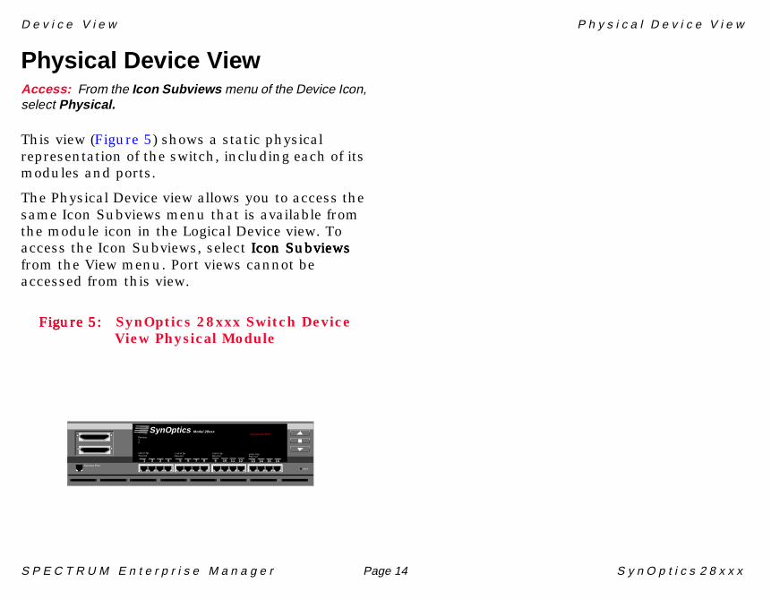
Physical Device ViewAccess: From the Icon Subviews menu of the Device Icon,select Physical.
This view (Figure 5) shows a static physical representation of the switch, including each of its modules and ports.
The Physical Device view allows you to access the same Icon Subviews menu that is available from the module icon in the Logical Device view. To access the Icon Subviews, select Icon Subviews Icon Subviews Icon Subviews Icon Subviews from the View menu. Port views cannot be accessed from this view.
Figure 5:Figure 5:Figure 5:Figure 5: SynOptics 28xxx Switch Device View Physical Module
Reset
1 2 3 4
SynOptics Model 28xxxOperational: RUN
5 6 7 8 9 10 11 12 13 14 15 161 2 3 4Service Port
Par tition12
Link H SpPart Col
Link H SpPart Col
Link H SpPart Col
Link H SpPart Col
S P E C T R U M E n t e r p r i s e M a n a g e r Page 15 S y n O p t i c s 2 8 x x x
Configuration Views
This section describes the Configuration views available for SynOptics 28xxx series switches in SPECTRUM.
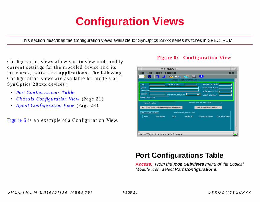
Configuration views allow you to view and modify current settings for the modeled device and its interfaces, ports, and applications. The following Configuration views are available for models of SynOptics 28xxx devices:
• Port Configurations Table• Chassis Configuration View (Page 21)• Agent Configuration View (Page 23)
Figure 6 is an example of a Configuration View.
Figure 6:Figure 6:Figure 6:Figure 6: Configuration View
Port Configurations TableAccess: From the Icon Subviews menu of the LogicalModule Icon, select Port Configurations .
JK2 of Type of Landscape X Primary
ÿþýüûþúùø÷÷öýõûôýóò
�ú�ô�üù�÷ù�ýü��òô�þ�ûõ�ù�ú÷�
�òô�þ�ûõ�ù�ò���
��þýûöù��ü��þ
�ÿùø��þ����ó��öù�óòôûõô���õþý÷ôýóò�óõûôýóò
ÿ����ÿ ���� ����ÿ�����
�óòôûõôù�ôûô��
ÿþýüûþúùø��þ���
��ü��þùó�ù�òô�þ�ûõ��
Device Configuration View
Interface Configuration TableSort Find Update
Redundancy and Model Reconfiguration Options Interface Address Translation
Index Description Type Bandwidth Physical Address Operation Status
���������i
SpectroGRAPH:
C o n f i g u r a t i o n V i e w s
S P E C T R U M E n t e r p r i s e M a n a g e r Page 16 S y n O p t i c s 2 8 x x x
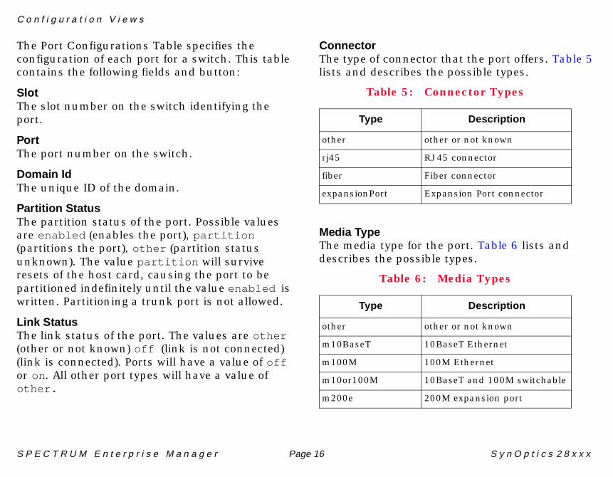
The Port Configurations Table specifies the configuration of each port for a switch. This table contains the following fields and button:
SlotThe slot number on the switch identifying the port.
PortThe port number on the switch.
Domain IdThe unique ID of the domain.
Partition StatusThe partition status of the port. Possible values are enabled (enables the port), partition (partitions the port), other (partition status unknown). The value partition will survive resets of the host card, causing the port to be partitioned indefinitely until the value enabled is written. Partitioning a trunk port is not allowed.
Link StatusThe link status of the port. The values are other(other or not known) off (link is not connected) (link is connected). Ports will have a value of off or on. All other port types will have a value of other.
ConnectorThe type of connector that the port offers. Table 5 lists and describes the possible types.
Media TypeThe media type for the port. Table 6 lists and describes the possible types.
Table 5: Connector Types
Type Description
other other or not known
rj45 RJ45 connector
fiber Fiber connector
expansionPort Expansion Port connector
Table 6: Media Types
Type Description
other other or not known
m10BaseT 10BaseT Ethernet
m100M 100M Ethernet
m10or100M 10BaseT and 100M switchable
m200e 200M expansion port
C o n f i g u r a t i o n V i e w s
S P E C T R U M E n t e r p r i s e M a n a g e r Page 17 S y n O p t i c s 2 8 x x x
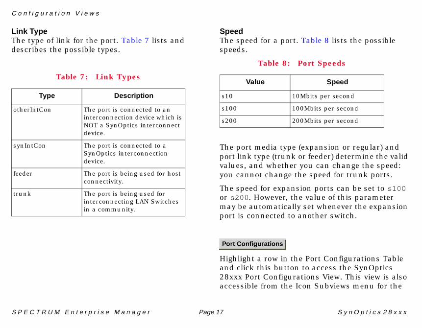
Link TypeThe type of link for the port. Table 7 lists and describes the possible types.
SpeedThe speed for a port. Table 8 lists the possible speeds.
The port media type (expansion or regular) and port link type (trunk or feeder) determine the valid values, and whether you can change the speed: you cannot change the speed for trunk ports.
The speed for expansion ports can be set to s100or s200 . However, the value of this parameter may be automatically set whenever the expansion port is connected to another switch.
Highlight a row in the Port Configurations Table and click this button to access the SynOptics 28xxx Port Configurations View. This view is also accessible from the Icon Subviews menu for the
Table 7: Link Types
Type Description
otherIntCon The port is connected to an interconnection device which is NOT a SynOptics interconnect device.
synIntCon The port is connected to a SynOptics interconnection device.
feeder The port is being used for host connectivity.
trunk The port is being used for interconnecting LAN Switches in a community.
Table 8: Port Speeds
Value Speed
s10 10Mbits per second
s100 100Mbits per second
s200 200Mbits per second
Port Configurations
C o n f i g u r a t i o n V i e w s
S P E C T R U M E n t e r p r i s e M a n a g e r Page 18 S y n O p t i c s 2 8 x x x
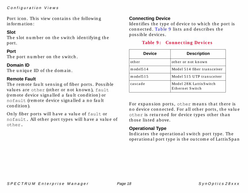
Port icon. This view contains the following information:
SlotThe slot number on the switch identifying the port.
PortThe port number on the switch.
Domain IDThe unique ID of the domain.
Remote FaultThe remote fault sensing of fiber ports. Possible values are other (other or not known), fault(remote device signalled a fault condition) or nofault (remote device signalled a no fault condition).
Only fiber ports will have a value of fault or nofault. All other port types will have a value of other.
Connecting DeviceIdentifies the type of device to which the port is connected. Table 9 lists and describes the possible devices.
For expansion ports, other means that there is no device connected. For all other ports, the value other is returned for device types other than those listed above.
Operational TypeIndicates the operational switch port type. The operational port type is the outcome of LattisSpan
Table 9: Connecting Devices
Device Description
other other or not known
model514 Model 514 fiber transceiver
model515 Model 515 UTP transceiver
cascade Model 28K LattisSwitch Ethernet Switch
S P E C T R U M E n t e r p r i s e M a n a g e r Page 19 S y n O p t i c s 2 8 x x x
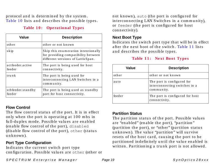
protocol and is determined by the system. Table 10 lists and describes the possible types.
Flow ControlThe flow control status of the port. It is in effect only when the port is operating at 100 mbs in full-duplex mode. Possible values are enabled (enable flow control of the port), disabled (disable flow control of the port), other (status unknown).
Port Type ConfigurationIndicates the current switch port type configuration. Possible values are other (other or
not known), auto (the port is configured for interconnecting LAN Switches in a community), or feeder (the port is configured for host connectivity).
Next Boot TypeIndicates the switch port type that will be in effect after the next boot of the switch. Table 11 lists and describes the possible types.
Partition StatusThe partition status of the port. Possible values are “enabled” (enable the port), “partition” (partition the port), or “other” (partition status unknown). The value “partition” will survive resets of the host card, causing the port to be partitioned indefinitely until the value enabled is written. Partitioning a trunk port is not allowed.
Table 10: Operational Types
Value Description
other other or not known
skip Skip this enumeration intentionally for providing compatibility between different versions of LattisSpan.
actfeeder.active feeder
The port is being used for host connectivity.
trunk The port is being used for interconnecting LAN Switches in a community.
stbfeeder.standby feeder
The port is being used as standby port for host connectivity.
Table 11: Next Boot Types
Value Description
other other or not known
auto The port is configured for interconnecting switches in a community.
feeder The port is configured for host connectivity.
C o n f i g u r a t i o n V i e w s
S P E C T R U M E n t e r p r i s e M a n a g e r Page 20 S y n O p t i c s 2 8 x x x
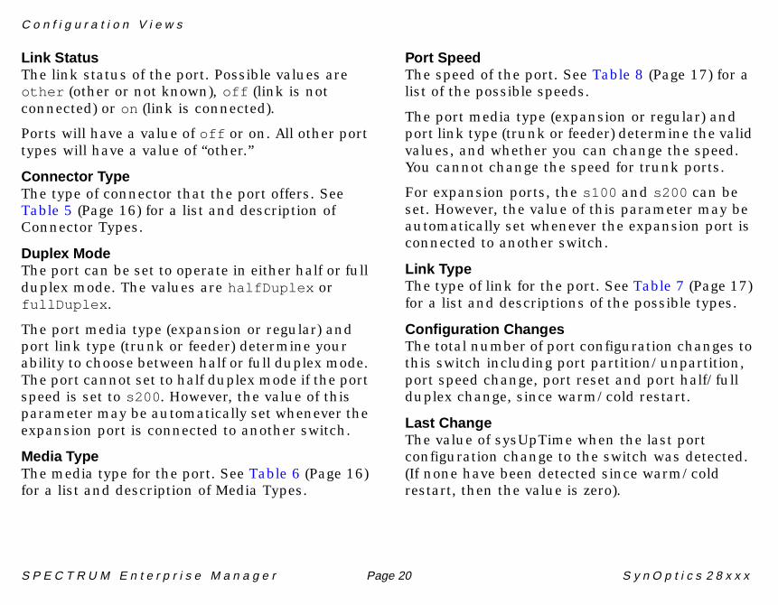
Link StatusThe link status of the port. Possible values are other (other or not known), off (link is not connected) or on (link is connected).
Ports will have a value of off or on. All other port types will have a value of “other.”
Connector TypeThe type of connector that the port offers. See Table 5 (Page 16) for a list and description of Connector Types.
Duplex ModeThe port can be set to operate in either half or full duplex mode. The values are halfDuplex or fullDuplex .
The port media type (expansion or regular) and port link type (trunk or feeder) determine your ability to choose between half or full duplex mode. The port cannot set to half duplex mode if the port speed is set to s200 . However, the value of this parameter may be automatically set whenever the expansion port is connected to another switch.
Media TypeThe media type for the port. See Table 6 (Page 16) for a list and description of Media Types.
Port SpeedThe speed of the port. See Table 8 (Page 17) for a list of the possible speeds.
The port media type (expansion or regular) and port link type (trunk or feeder) determine the valid values, and whether you can change the speed. You cannot change the speed for trunk ports.
For expansion ports, the s100 and s200 can be set. However, the value of this parameter may be automatically set whenever the expansion port is connected to another switch.
Link TypeThe type of link for the port. See Table 7 (Page 17) for a list and descriptions of the possible types.
Configuration ChangesThe total number of port configuration changes to this switch including port partition/unpartition, port speed change, port reset and port half/full duplex change, since warm/cold restart.
Last ChangeThe value of sysUpTime when the last port configuration change to the switch was detected. (If none have been detected since warm/cold restart, then the value is zero).
C o n f i g u r a t i o n V i e w s
S P E C T R U M E n t e r p r i s e M a n a g e r Page 21 S y n O p t i c s 2 8 x x x
Port ResetAction object to reset a port. Possible values are “reset” and “resetOK.”
Chassis Configuration ViewAccess: From the Icon Subviews menu for the LogicalModule icon, select Chassis Configuration.
This view contains the following information:
Chassis Switch IDThe unique identifier for the switch.
Chassis TypeThe chassis type.
Chassis DescriptionA description of the chassis.
Chassis LocationIndicates the physical location of the chassis (e.g., “fourth floor wiring closet in building A”).
Chassis ContactIdentifies the contact person for the chassis.
Chassis VersionThe major revision designation of the chassis, if available.
Chassis Serial NumberThe serial number of the chassis, if available.
Total Configuration ChangesIndicates the total number of configuration changes (other than physical additions or removals) across all boards in the chassis that have been detected since cold/warm start of the agent.
Last Configuration ChangesThe time when the last configuration change (other than physical additions or removals) on any board in the chassis was detected. If none have been detected since cold/warm start of the agent, then the value is zero.
System DateThe system date in mm/dd/yy format.
System TimeThe system time in hh:mm:ss format.
Number of FansIndicates the total number of fans in the chassis.
C o n f i g u r a t i o n V i e w s
S P E C T R U M E n t e r p r i s e M a n a g e r Page 22 S y n O p t i c s 2 8 x x x
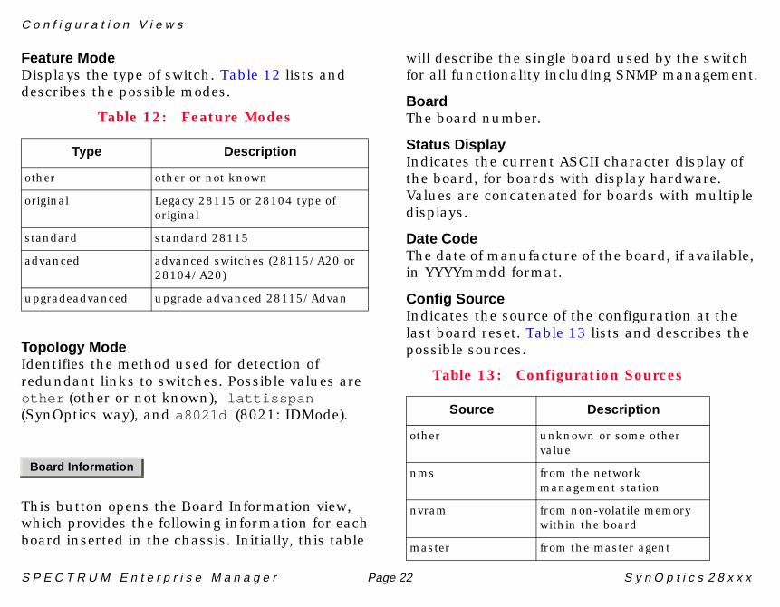
Feature ModeDisplays the type of switch. Table 12 lists and describes the possible modes.
Topology ModeIdentifies the method used for detection of redundant links to switches. Possible values are other (other or not known), lattisspan (SynOptics way), and a8021d (8021: IDMode).
This button opens the Board Information view, which provides the following information for each board inserted in the chassis. Initially, this table
will describe the single board used by the switch for all functionality including SNMP management.
BoardThe board number.
Status DisplayIndicates the current ASCII character display of the board, for boards with display hardware. Values are concatenated for boards with multiple displays.
Date CodeThe date of manufacture of the board, if available, in YYYYmmdd format.
Config SourceIndicates the source of the configuration at the last board reset. Table 13 lists and describes the possible sources.
Table 12: Feature Modes
Type Description
other other or not known
original Legacy 28115 or 28104 type of original
standard standard 28115
advanced advanced switches (28115/A20 or 28104/A20)
upgradeadvanced upgrade advanced 28115/Advan
Board Information
Table 13: Configuration Sources
Source Description
other unknown or some other value
nms from the network management station
nvram from non-volatile memory within the board
master from the master agent
C o n f i g u r a t i o n V i e w s
S P E C T R U M E n t e r p r i s e M a n a g e r Page 23 S y n O p t i c s 2 8 x x x
Config ChangesThe total number of configuration changes for the board that have been detected since cold/warm start of the agent or since the board was inserted.
Config TimeIndicates the time when the last configuration change on the board was detected.
BaseboardDistinguishes the baseboard type from the chassis type.
Agent Configuration ViewAccess: From the Icon Subviews menu for the LogicalModule icon, select Agent Configuration.
This view contains the following information:
RAM VersionThe version of the agent in the form “major.minor.maintenance [letters].”
Local Storage VersionThe version of the agent image saved in local storage such as flash memory in the form “major.minor.maintenance[letters].” If not known or not available, then the value is a zero length string.
Initial Boot Info SourceAllows you to choose the initial boot information source. Possible values are other , local , and net using bootp.
Current GatewayThe gateway currently in use.
Next Boot GatewayThe IP address of the default gateway (router) for the agent to use after the next boot.
Schedule BootThe time at which the device is scheduled to reboot. Reboot can be scheduled up to seven (7) days in advance.
Cancel Schedule BootAllows cancellation of scheduled boot. Selections are cancel and other.
Next Boot Image Load SourceDisplays where to get the firmware image for the next time it boots. Possible values are local (stored on the device), net (going out to another computer and getting the image), or other.
Image Boot NextAllows you to select a firmware image type you have downloaded and stored. Possible selections are other , image1 , image2 , or latest .
C o n f i g u r a t i o n V i e w s
S P E C T R U M E n t e r p r i s e M a n a g e r Page 24 S y n O p t i c s 2 8 x x x
Boot Image 1The flashbank which is set to load an image when rebooting, or which image to store when downloading.
Boot Image 2See Boot Image 1.
Next Boot IP AddressThe IP address of the interface for the next boot.
Load Server AddressThe IP address of the load server for the configuration file and/or the image file.
Config File NameThe name of the configuration file associated with the interface.
Image File NameThe name of the firmware image file(s) associated with the interface. Some agents in special situations may support a value which contains multiple file names instead of a single file name. Multiple names are specified as a list of file names separated by semicolons.
Next Boot Net MaskThe subnet mask for the interface for the next boot.
DownloadAllows you to download a new image to the agent. Possible values are other (agent in unknown state), running (agent running after download), and download (re-download a new image).
Reboot AgentAllows you to reboot the agent.
Table 14 lists the possible values.
Off-Page Reference PanelThe Off-Page Reference panel in the top-left section of the DevTop view displays icons representing network devices that SPECTRUM “knows” are connected to the SynOptics switch, but for which a specific port connection has not been determined. These triangular-shaped icons must be connected to a port for SPECTRUM to
Table 14: Reboot Agent Values
Value Description
other agent in unknown or other state
running agent running
reset soft reset
hard reset hard reset
S P E C T R U M E n t e r p r i s e M a n a g e r Page 25 S y n O p t i c s 2 8 x x x
correctly monitor and manage the connected device.
To connect an Off-Page Reference icon to a port, follow these steps:
1 Select EditEditEditEdit from the File menu.
2 Click on the Off-Page Reference icon.
S P E C T R U M E n t e r p r i s e M a n a g e r Page 26 S y n O p t i c s 2 8 x x x
Application Views
This section describes the Application views available for models of SynOptics 28xxx devices in SPECTRUM.
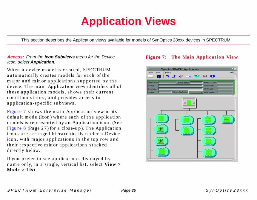
Access: From the Icon Subviews menu for the DeviceIcon, select Application .
When a device model is created, SPECTRUM automatically creates models for each of the major and minor applications supported by the device. The main Application view identifies all of these application models, shows their current condition status, and provides access to application-specific subviews.
Figure 7 shows the main Application view in its default mode (Icon) where each of the application models is represented by an Application icon. (See Figure 8 (Page 27) for a close-up). The Application icons are arranged hierarchically under a Device icon, with major applications in the top row and their respective minor applications stacked directly below.
If you prefer to see applications displayed by name only, in a single, vertical list, select View > Mode > List.
Figure 7:Figure 7:Figure 7:Figure 7: The Main Application View
SpectroGRAPH: Application
Model Name
Contact
Description
Location Primary Application
System Up Time
Manufacturer
Device Type
Serial Number
Network Address
* File View Help?Options
IP R outing
CiscoIPApp
M IB-II
SN MP2_Agent
ICM P
IC MP_App
Sy stem
System2_App
TC P
T CP2_App
SN MP2_Agent
IC MP_App
CP2_App
System2_App
N ovel l
C iscoNovellApp
AppleTalk
ApplTlk RtrApp
Bridge App
Bridge_App
Static
Static_App
CiscoChas App
CiscoCha
C hassis
IP R outing
CiscoIPApp
i
A p p l i c a t i o n V i e w s A p p l i c a t i o n I c o n s
S P E C T R U M E n t e r p r i s e M a n a g e r Page 27 S y n O p t i c s 2 8 x x x
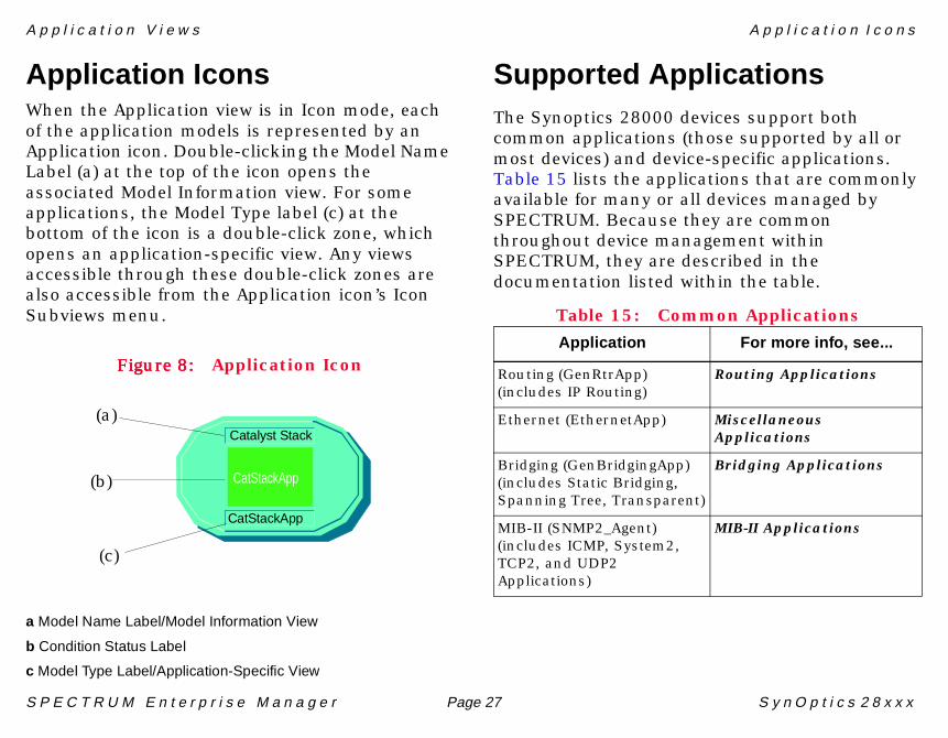
Application IconsWhen the Application view is in Icon mode, each of the application models is represented by an Application icon. Double-clicking the Model Name Label (a) at the top of the icon opens the associated Model Information view. For some applications, the Model Type label (c) at the bottom of the icon is a double-click zone, which opens an application-specific view. Any views accessible through these double-click zones are also accessible from the Application icon’s Icon Subviews menu.
Figure 8:Figure 8:Figure 8:Figure 8: Application Icon
a Model Name Label/Model Information View
b Condition Status Label
c Model Type Label/Application-Specific View
Supported ApplicationsThe Synoptics 28000 devices support both common applications (those supported by all or most devices) and device-specific applications. Table 15 lists the applications that are commonly available for many or all devices managed by SPECTRUM. Because they are common throughout device management within SPECTRUM, they are described in the documentation listed within the table.
Table 15: Common Applications
CatStackApp
Catalyst Stack
CatStackApp
(a)
(b)
(c)
Application For more info, see...
Routing (GenRtrApp) (includes IP Routing)
Routing Applications
Ethernet (EthernetApp) Miscellaneous Applications
Bridging (GenBridgingApp)(includes Static Bridging, Spanning Tree, Transparent)
Bridging Applications
MIB-II (SNMP2_Agent) (includes ICMP, System2, TCP2, and UDP2 Applications)
MIB-II Applications
A p p l i c a t i o n V i e w s S y n O p t i c s 2 8 x x x C o m m o n A p p l i c a t i o n
S P E C T R U M E n t e r p r i s e M a n a g e r Page 28 S y n O p t i c s 2 8 x x x
SynOptics 28xxx CommonApplication
The following submenus, subviews and tables are available through the Syn28CommonApp’s Icon Subviews menu:
• Agent Information View• Trunk Information View (Page 34)• Switch Community View (Page 30)
Agent Information ViewAccess: From the Icon Subviews menu for theSyn28CommonApp Application icon, select AgentInformation .
This selection accesses the Agent Configuration and Trap Receiver views, which are described below.
Agent Configuration ViewSee Agent Configuration View (Page 23) for a description of this view.
Trap Receiver ViewThis view presents trap receiver information in tabular form and allows you to determine which
addresses will receive traps generated by the switch.
Maximum EntriesIndicates the maximum number of rows in the trap receiver table.
Current EntriesThe current number of rows in the trap receiver table.
Next Available EntryThe index of the next available row to be created in the trap receiver table. A value of zero means that the table is full and no more rows can be added.
Trap Receiver TableProvides a table of trap-receiving managers.
ReceiverIndicates a row in the trap receiver table.
Receiver StatusUsed to create and delete rows in the table.
S P E C T R U M E n t e r p r i s e M a n a g e r Page 29 S y n O p t i c s 2 8 x x x
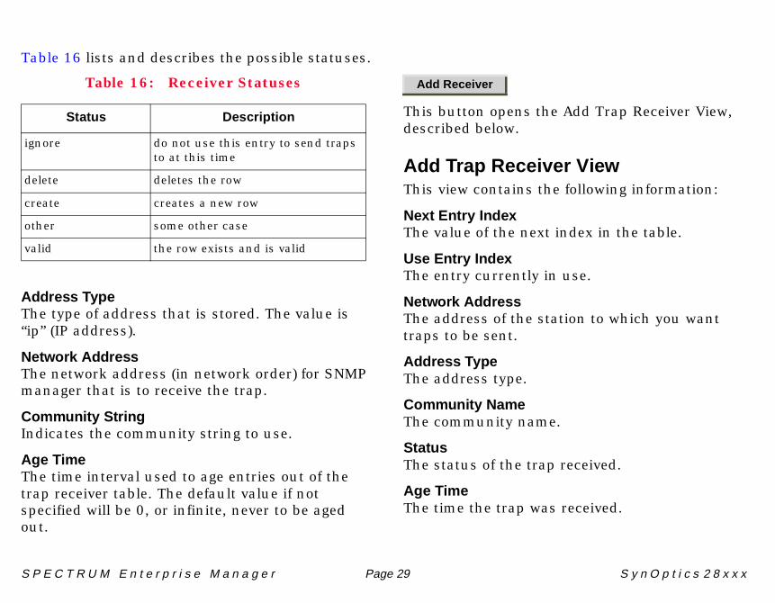
Table 16 lists and describes the possible statuses.
Address TypeThe type of address that is stored. The value is “ip” (IP address).
Network AddressThe network address (in network order) for SNMP manager that is to receive the trap.
Community StringIndicates the community string to use.
Age TimeThe time interval used to age entries out of the trap receiver table. The default value if not specified will be 0, or infinite, never to be aged out.
This button opens the Add Trap Receiver View, described below.
Add Trap Receiver ViewThis view contains the following information:
Next Entry IndexThe value of the next index in the table.
Use Entry IndexThe entry currently in use.
Network AddressThe address of the station to which you want traps to be sent.
Address TypeThe address type.
Community NameThe community name.
StatusThe status of the trap received.
Age TimeThe time the trap was received.
Table 16: Receiver Statuses
Status Description
ignore do not use this entry to send traps to at this time
delete deletes the row
create creates a new row
other some other case
valid the row exists and is valid
Add Receiver
A p p l i c a t i o n V i e w s
S P E C T R U M E n t e r p r i s e M a n a g e r Page 30 S y n O p t i c s 2 8 x x x
Switch Community ViewAccess: From the Icon Subviews menu for theSyn28CommonApp Application icon, select SwitchCommunity.
This selection contains a submenu: Domain, Trunk Information, Switch List, and History Logs.
DomainAccess: From the Icon Subviews menu for theSyn28CommonApp Application icon, select SwitchCommunity > Domain.
This view contains the following fields and the Domain Table:
Switch TypeThe type of switch: Master or Normal .
Operating ModeAllows choice of operating mode. Possible selections are basic (default Operation Mode (no user domains)), virtual (port has been configured in a user domain), or other.
Number of DomainsDisplays the number of domains in the network.
Number of Ports in DomainsDisplays the number of ports in all the domains.
Domain TableThe Domain Table identifies the domains in the switch community. Only those domains that are related to the switch can be seen when communicating to a non-master switch. Only the master switch has the entire domain information for a switch community.
This table contains the following fields and buttons:
Domain IdThe unique ID of the domain.
Domain NameThe name of the domain.
A p p l i c a t i o n V i e w s
S P E C T R U M E n t e r p r i s e M a n a g e r Page 31 S y n O p t i c s 2 8 x x x
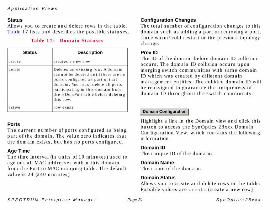
StatusAllows you to create and delete rows in the table. Table 17 lists and describes the possible statuses.
PortsThe current number of ports configured as being part of the domain. The value zero indicates that the domain exists, but has no ports configured.
Age TimeThe time interval (in units of 10 minutes) used to age out all MAC addresses within this domain from the Port to MAC mapping table. The default value is 24 (240 minutes).
Configuration ChangesThe total number of configuration changes to this domain such as adding a port or removing a port, since warm/cold restart or the previous topology change.
Prev IDThe ID of the domain before domain ID collision occurs. The domain ID collision occurs upon merging switch communities with same domain ID which was created by different domain management entities. The collided domain ID will be reassigned to guarantee the uniqueness of domain ID throughout the switch community.
Highlight a line in the Domain view and click this button to access the SynOptics 28xxx Domain Configuration View, which contains the following information.
Domain IDThe unique ID of the domain.
Domain NameThe name of the domain.
Domain StatusAllows you to create and delete rows in the table. Possible values are create (create a new row),
Table 17: Domain Statuses
Status Description
create creates a new row
delete Deletes an existing row. A domain cannot be deleted until there are no ports configured as part of that domain. You must delete all ports participating in this domain from the lsDomPortTable before deleting this row.
active row existsDomain Configuration
A p p l i c a t i o n V i e w s
S P E C T R U M E n t e r p r i s e M a n a g e r Page 32 S y n O p t i c s 2 8 x x x
delete (deletes an existing row), or active (row exists). A domain cannot be deleted until there are no ports configured as part of that domain. You must delete all ports participating in this domain from the lsDomPortTable before deleting this row.
Number of PortsThe current number of ports configured as being part of the domain. The value zero indicates that the domain exists, but has no ports configured in it.
MAC Age TimeThe time interval used to age out all MAC addresses within this domain from the Port to MAC mapping table. The default value is 300 .
A value of zero means the table never aged out entries.
Total ChangesThe total number of configuration changes to this domain such as adding port or removing port, since warm/cold restart or the previous topology change.
System Up TimeThe amount of time the system has been running.
Previous Domain IDThe ID number of the previously domain configuration.
Highlight a line in the Domain view and click this button to access the SynOptics 28xxx Domain Port View. This view contains the Domain Port Table which identifies all ports on the specified domain.
Only those Domain-Ports information within a switch can be retrieved when communicating to a non-master switch. An entire Domain-Ports information within a switch community can be retrieved through the master switch only.
Domain Port TableThe Domain Port Table contains the following information:
Domain IDThe ID of the domain containing the port.
Switch IDThe unique identifier for the switch containing the port.
Domain Port
A p p l i c a t i o n V i e w s
S P E C T R U M E n t e r p r i s e M a n a g e r Page 33 S y n O p t i c s 2 8 x x x
SlotThe slot number on the switch identifying the port.
PortThe port number on the switch.
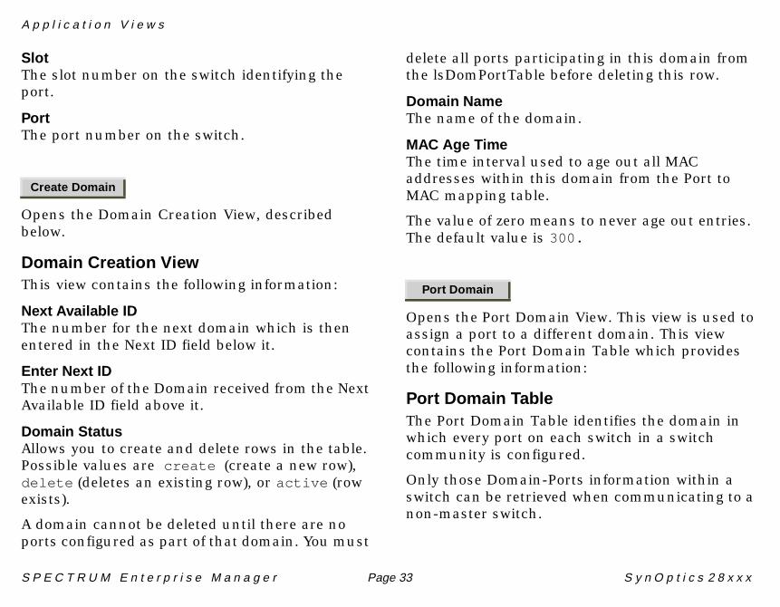
Opens the Domain Creation View, described below.
Domain Creation ViewThis view contains the following information:
Next Available IDThe number for the next domain which is then entered in the Next ID field below it.
Enter Next IDThe number of the Domain received from the Next Available ID field above it.
Domain StatusAllows you to create and delete rows in the table. Possible values are create (create a new row), delete (deletes an existing row), or active (row exists).
A domain cannot be deleted until there are no ports configured as part of that domain. You must
delete all ports participating in this domain from the lsDomPortTable before deleting this row.
Domain NameThe name of the domain.
MAC Age TimeThe time interval used to age out all MAC addresses within this domain from the Port to MAC mapping table.
The value of zero means to never age out entries. The default value is 300.
Opens the Port Domain View. This view is used to assign a port to a different domain. This view contains the Port Domain Table which provides the following information:
Port Domain TableThe Port Domain Table identifies the domain in which every port on each switch in a switch community is configured.
Only those Domain-Ports information within a switch can be retrieved when communicating to a non-master switch.
Create Domain
Port Domain
A p p l i c a t i o n V i e w s
S P E C T R U M E n t e r p r i s e M a n a g e r Page 34 S y n O p t i c s 2 8 x x x
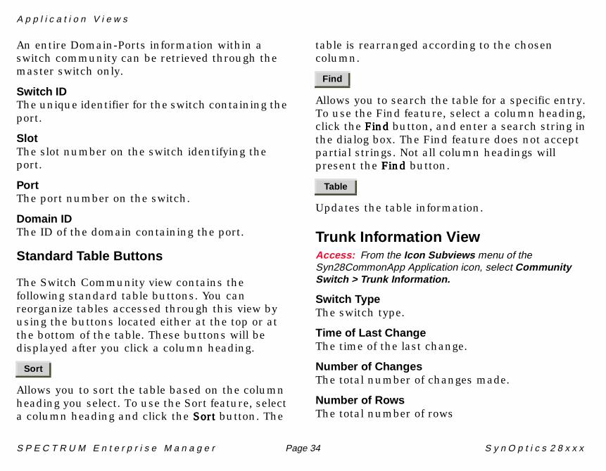
An entire Domain-Ports information within a switch community can be retrieved through the master switch only.
Switch IDThe unique identifier for the switch containing the port.
SlotThe slot number on the switch identifying the port.
PortThe port number on the switch.
Domain IDThe ID of the domain containing the port.
Standard Table Buttons
The Switch Community view contains the following standard table buttons. You can reorganize tables accessed through this view by using the buttons located either at the top or at the bottom of the table. These buttons will be displayed after you click a column heading.
Allows you to sort the table based on the column heading you select. To use the Sort feature, select a column heading and click the Sort Sort Sort Sort button. The
table is rearranged according to the chosen column.
Allows you to search the table for a specific entry. To use the Find feature, select a column heading, click the Find Find Find Find button, and enter a search string in the dialog box. The Find feature does not accept partial strings. Not all column headings will present the FindFindFindFind button.
Updates the table information.
Trunk Information ViewAccess: From the Icon Subviews menu of theSyn28CommonApp Application icon, select CommunitySwitch > Trunk Information.
Switch TypeThe switch type.
Time of Last ChangeThe time of the last change.
Number of ChangesThe total number of changes made.
Number of RowsThe total number of rows
Sort
Find
Table
A p p l i c a t i o n V i e w s
S P E C T R U M E n t e r p r i s e M a n a g e r Page 35 S y n O p t i c s 2 8 x x x
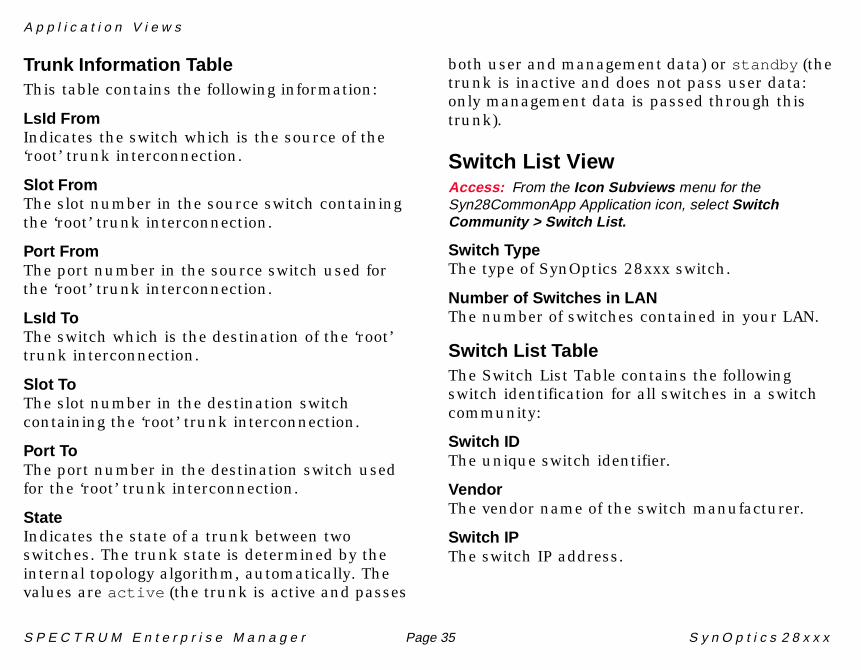
Trunk Information TableThis table contains the following information:
LsId FromIndicates the switch which is the source of the ‘root’ trunk interconnection.
Slot FromThe slot number in the source switch containing the ‘root’ trunk interconnection.
Port FromThe port number in the source switch used for the ‘root’ trunk interconnection.
LsId ToThe switch which is the destination of the ‘root’ trunk interconnection.
Slot ToThe slot number in the destination switch containing the ‘root’ trunk interconnection.
Port ToThe port number in the destination switch used for the ‘root’ trunk interconnection.
StateIndicates the state of a trunk between two switches. The trunk state is determined by the internal topology algorithm, automatically. The values are active (the trunk is active and passes
both user and management data) or standby (the trunk is inactive and does not pass user data: only management data is passed through this trunk).
Switch List ViewAccess: From the Icon Subviews menu for theSyn28CommonApp Application icon, select SwitchCommunity > Switch List.
Switch TypeThe type of SynOptics 28xxx switch.
Number of Switches in LANThe number of switches contained in your LAN.
Switch List TableThe Switch List Table contains the following switch identification for all switches in a switch community:
Switch IDThe unique switch identifier.
VendorThe vendor name of the switch manufacturer.
Switch IPThe switch IP address.
A p p l i c a t i o n V i e w s
S P E C T R U M E n t e r p r i s e M a n a g e r Page 36 S y n O p t i c s 2 8 x x x
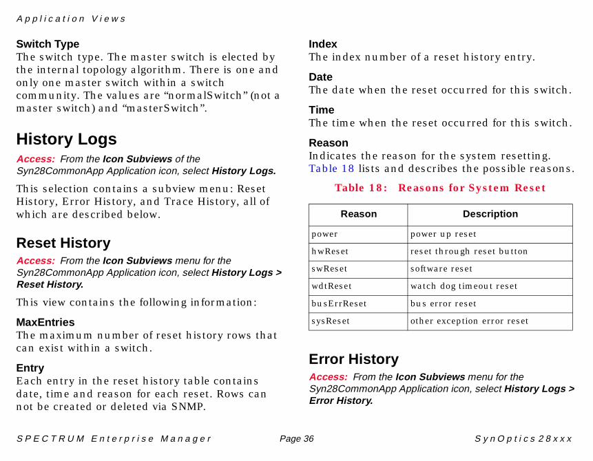
Switch TypeThe switch type. The master switch is elected by the internal topology algorithm. There is one and only one master switch within a switch community. The values are “normalSwitch” (not a master switch) and “masterSwitch”.
History LogsAccess: From the Icon Subviews of theSyn28CommonApp Application icon, select History Logs.
This selection contains a subview menu: Reset History, Error History, and Trace History, all of which are described below.
Reset HistoryAccess: From the Icon Subviews menu for theSyn28CommonApp Application icon, select History Logs >Reset History.
This view contains the following information:
MaxEntriesThe maximum number of reset history rows that can exist within a switch.
EntryEach entry in the reset history table contains date, time and reason for each reset. Rows can not be created or deleted via SNMP.
IndexThe index number of a reset history entry.
DateThe date when the reset occurred for this switch.
TimeThe time when the reset occurred for this switch.
ReasonIndicates the reason for the system resetting. Table 18 lists and describes the possible reasons.
Error HistoryAccess: From the Icon Subviews menu for theSyn28CommonApp Application icon, select History Logs >Error History.
Table 18: Reasons for System Reset
Reason Description
power power up reset
hwReset reset through reset button
swReset software reset
wdtReset watch dog timeout reset
busErrReset bus error reset
sysReset other exception error reset
A p p l i c a t i o n V i e w s
S P E C T R U M E n t e r p r i s e M a n a g e r Page 37 S y n O p t i c s 2 8 x x x
This view contains the Error Log Table, described below.
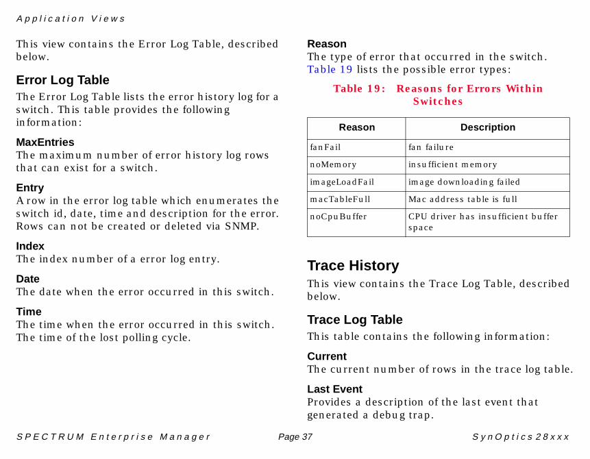
Error Log TableThe Error Log Table lists the error history log for a switch. This table provides the following information:
MaxEntriesThe maximum number of error history log rows that can exist for a switch.
EntryA row in the error log table which enumerates the switch id, date, time and description for the error. Rows can not be created or deleted via SNMP.
IndexThe index number of a error log entry.
DateThe date when the error occurred in this switch.
TimeThe time when the error occurred in this switch. The time of the lost polling cycle.
ReasonThe type of error that occurred in the switch. Table 19 lists the possible error types:
Trace HistoryThis view contains the Trace Log Table, described below.
Trace Log TableThis table contains the following information:
CurrentThe current number of rows in the trace log table.
Last EventProvides a description of the last event that generated a debug trap.
Table 19: Reasons for Errors Within Switches
Reason Description
fanFail fan failure
noMemory insufficient memory
imageLoadFail image downloading failed
macTableFull Mac address table is full
noCpuBuffer CPU driver has insufficient buffer space
A p p l i c a t i o n V i e w s S y 2 8 x E n S w c h A p p
S P E C T R U M E n t e r p r i s e M a n a g e r Page 38 S y n O p t i c s 2 8 x x x
TableLists the event trace log for a switch.
EntryDisplays a row in the event trace log table which enumerates a subsystem id, an event code, an event count, date and time, an option, and a description of the event. Rows cannot be created or deleted via SNMP.
IndexThe index number of an event log entry.
Description of EventProvides a description of the event.
Sy28xEnSwchApp
The following application-specific subviews are available from this application:
• Port Configurations Table (Page 15)• Port to MAC View (Page 38)
Port Configurations TableAccess: From the Icon Subviews menu for theSy28xEnSwchApp Application icon, select PortConfigurations.
This subviews menu selection opens the SynOptics 28xxx Port Configurations View. See Port Configurations Table (Page 15) for a description of this view.
Port to MAC ViewAccess: From the Icon Subviews for theSy28xEnSwchApp Application icon, select Port to MAC.
This view contains the Port to MAC Table that identifies all the MAC addresses seen on each feeder and trunk port.
The following information is shown for each port:
The Port to MAC Table contains a mapping between a port and all of the MAC addresses seen on that port. This includes both feeder and trunk ports.
SlotThe slot number of the switch containing the port.
PortThe port number on the switch.
MAC AddressThe MAC address seen on the port.
S P E C T R U M E n t e r p r i s e M a n a g e r Page 39 S y n O p t i c s 2 8 x x x
Model Information Views
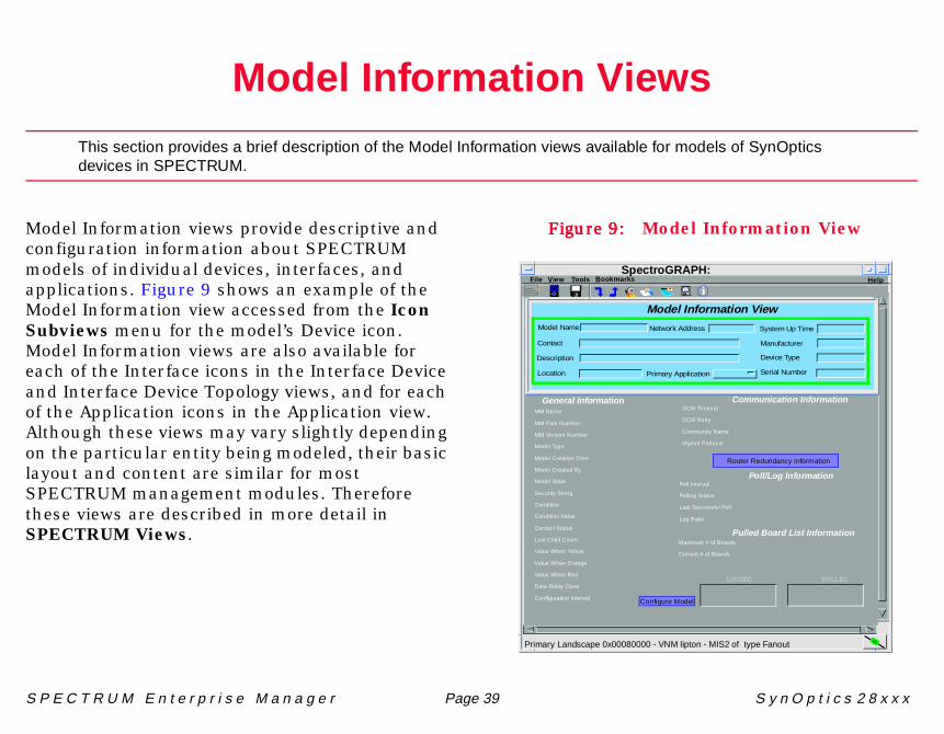
This section provides a brief description of the Model Information views available for models of SynOpticsdevices in SPECTRUM.
Model Information views provide descriptive and configuration information about SPECTRUM models of individual devices, interfaces, and applications. Figure 9 shows an example of the Model Information view accessed from the Icon Subviews menu for the model’s Device icon. Model Information views are also available for each of the Interface icons in the Interface Device and Interface Device Topology views, and for each of the Application icons in the Application view. Although these views may vary slightly depending on the particular entity being modeled, their basic layout and content are similar for most SPECTRUM management modules. Therefore these views are described in more detail in SPECTRUM Views.
Figure 9:Figure 9:Figure 9:Figure 9: Model Information View
Primary Landscape 0x00080000 - VNM lipton - MIS2 of type Fanout
Help
General Info rmationMM Name
MM Park Number
MM Version Number
Model Type
Model Creation Time
Model Created By
Model State
Security String
Condition
Condition Value
Contact Status
Lost Child Count
Value When Yellow
Value When Orange
Value When Red
Data Relay Class
Configuration Interval
Communication Information
Poll/Log Information
DCM Timeout
DCM Retry
Community Name
Mgmnt Protocol
Poll Interval
Polling Status
Last Successful Poll
Log Ratio
LOGGED POLLED
Configure Model
Router Redundancy Information
Pulled Board List InformationMaximum # of Boards
Current # of Boards
Model Information ViewModel Name
Contact
Description
Location
Network Address
Primary Application
System Up Time
Manufacturer
Device Type
Serial Number
File V iew Tools BookmarksSpectroGRAPH:
i
S P E C T R U M E n t e r p r i s e M a n a g e r Page 40 S y n O p t i c s 2 8 x x x
41
Index
AAdd Trap Receiver View 29Agent Configuration View 23, 28Agent Information 28Align Errors 12Application
Bridging (GenBridgingApp) 27Ethernet (EthernetApp) 27MIB-II (SNMP2_Agent) 27Routing (GenRtrApp) 27
Application View 26
BBoot Image 1 24Boot Image 2 24Buffer Overflows 13
CChassis Configuration View 21Chassis Contact 21Chassis Description 21Chassis Location 21Chassis Serial Number 21
Chassis Switch ID 21Chassis Type 21Chassis Version 21Common Applications 26Configuration View 15Congestion 13Connecting Device 18Connector 16Crc Errors 12
DDevice
View 8Configuration 8
Domain 30Domain Creation View 33Domain ID 18Domain Id 16, 30Domain Table 30Dynamic
Representation 8
EEdit 25
Enable/Disable Port 13Error History 36
FFind
Button 34Flow Control 19Frames 13
GGood Frames 12
HHistory Logs 36
IInternal Received 13Internal Transmit 12Internal-to-Network Statistics 13
I n d e x I n d e x
S P E C T R U M E n t e r p r i s e M a n a g e r Page 41 S y n O p t i c s 2 8 x x x
LLast Configuration Changes 21Link Status 16Link Type 17Local Storage Version 23Logical Device View 8Logical Representation 8LsId From 35LsId To 35
MMedia Type 16Module
Identifier 9Number 9
Module Status 9
NNetwork Received 12Network Transmit 13Network-to-Internal Statistics 12Next Boot Gateway 23Next Boot Image Load Source 23Next Boot Type 19
OOff-Page Reference Panel 24Operational Type 18Overruns 12
PPartition Status 16, 19Physical Device View 14Port
Identifier 9Status 9
Port Configurations Table 15Port Reset 21Port Speed 10Port Statistics 12Port to MAC View 38Port Type 10Port Type Configuration 19
RRAM Version 23Receiver 28Receiver Status 28Remote Fault 18Reset History 36Restricted Rights Notice 2
SSlot 16Sort Button 34SPECTRUM Support 6SPMA
And the Token Ring MicroLAN Switch Module 6
Static 8Status Display 22Switch Community 30Switch Community View 11Switch IP 35Switch List View 35Sy28xEnSwchApp 38Syn28CommonApp 28
TTable Buttons 34Topology Mode 22Total Configuration Changes 21Trace History 37Trademarks 2Trap Receiver Table 28Trap Receiver View 28Trunk Information View 34


