Page 1
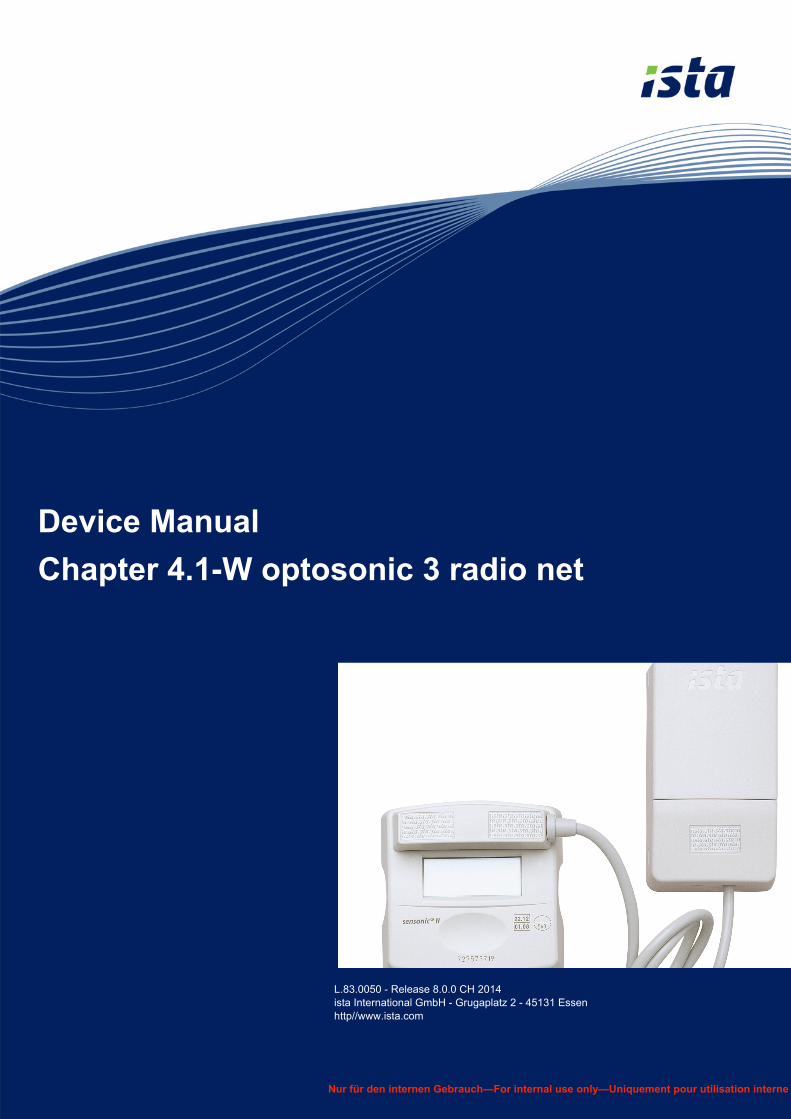
Device Manual
Chapter 4.1-W optosonic 3 radio net
L.83.0050 - Release 8.0.0 CH 2014ista International GmbH - Grugaplatz 2 - 45131 Essenhttp//www.ista.com
Nur für den internen Gebrauch—For internal use only—Uniquement pour utilisation interne
Page 2
L.83.0050 - Release 8.0.0 CH 2014ista International GmbH - Grugaplatz 2 - 45131 Essen
http://www.ista.com
Nu
r fü
r d
en
inte
rne
n G
eb
rau
ch —
Fo
r in
tern
al u
se o
nly
— U
niq
uem
en
t p
ou
r u
tili
sat
ion
inte
rne
Table of contents
1 Device data 3
1.1 General information 3
1.2 Device display 3
1.3 Technical data 4
1.4 Main and connection dimensions 5
2 Item numbers 6
3 Installation 7
3.1 Screwed installation 7
3.2 Installation with cable ties 7
3.2.1 With mounting plate 7
3.2.2 Without mounting plate 7
3.3 Final steps 8
4 Commissioning 9
5 Exchange 10
5.1 Preparatory steps 10
5.2 For installation on mounting plate 10
5.3 If installing without mounting plate 10
6 Reading 11
6.1 Radio reading AMM 11
6.2 Radio reading Walk by 11
7 Disposal 12
Device Manual2/12 4.1-W optosonic 3 radio net
Page 3
L.83.0050 - Release 8.0.0 CH 2014ista International GmbH - Grugaplatz 2 - 45131 Essenhttp//www.ista.com
Nu
r fü
r d
en
inte
rne
n G
eb
rau
ch —
Fo
r in
tern
al u
se
on
ly —
Un
iqu
emen
t p
ou
r u
tili
sa
tio
n in
tern
e
1.1 General information
Device group Systems
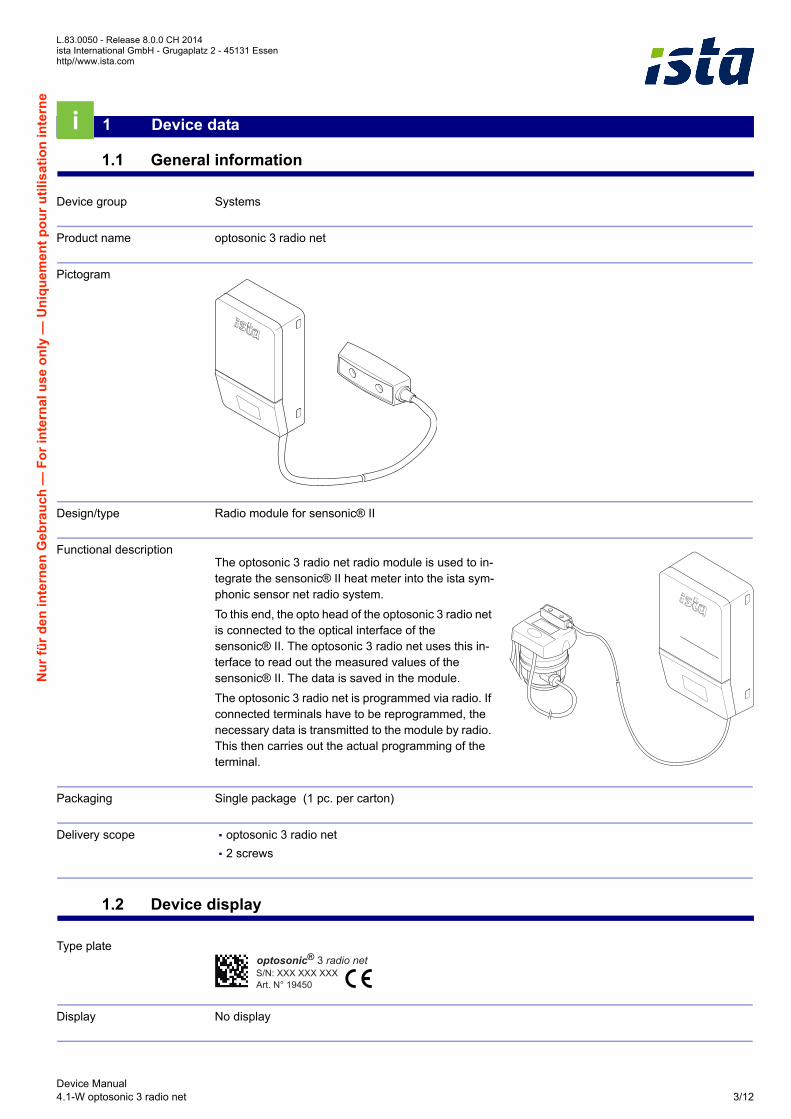
Product name optosonic 3 radio net
Pictogram
Design/type Radio module for sensonic® II
Functional descriptionThe optosonic 3 radio net radio module is used to in-tegrate the sensonic® II heat meter into the ista sym-phonic sensor net radio system.
To this end, the opto head of the optosonic 3 radio net is connected to the optical interface of the sensonic® II. The optosonic 3 radio net uses this in-terface to read out the measured values of the sensonic® II. The data is saved in the module.
The optosonic 3 radio net is programmed via radio. If connected terminals have to be reprogrammed, the necessary data is transmitted to the module by radio. This then carries out the actual programming of the terminal.
Packaging Single package (1 pc. per carton)
Delivery scope ▪ optosonic 3 radio net
▪ 2 screws
1.2 Device display
Type plate
Display No display
1 Device data
Art. N° 19450S/N: XXX XXX XXXoptosonic® 3 radio net
Device Manual4.1-W optosonic 3 radio net 3/12
Page 4
L.83.0050 - Release 8.0.0 CH 2014ista International GmbH - Grugaplatz 2 - 45131 Essen
http://www.ista.com
Nu
r fü
r d
en
inte
rne
n G
eb
rau
ch —
Fo
r in
tern
al u
se o
nly
— U
niq
uem
en
t p
ou
r u
tili
sat
ion
inte
rne
1.3 Technical data
Functional principle Optical read-out of connected counters
Interfaces ▪ Output: Radio interface for the ista radio system symphonic sensor net.
▪ Input: Opto head (protected against reversed polarity), cable length 0.5 m.
Radio interface ▪ Compatible with symphonic sensor net
▪ Transmission power: < 10 mW
▪ Radio frequency: 868 MHz
▪ Duration of transmission telegram: < 10 msec/transmission
▪ Transmission rate: ~ 90 kbaud (bit/sec)
▪ Transmission method: bidirectional
▪ Data integrity: encrypted transfer
Weight 0.110 kg
Material ABS
Casing colour RAL 9002
CE label 1999/5/EC
Storage Temperature:
▪ 1st year: -25 °C to +70 °C
▪ then 0 °C to +70 °C
To be stored in a dry place
Ambient temperature 0 °C - 70 °C
Relative humidity 5 % - 95 %
Protection class IP54 acc. to EN 60529
i.e.:
▪ Protection against foreign objects: Protects against damaging amount of dust.
▪ Protects against contact: complete protection against contact.
▪ Protection against water: Protection against splash water on all sides.
Power supply 3 V lithium battery
Life cycle 10 years + 1 year reserve + 1 year storage
Technology Integrated circuit (standard)
Parameterisation data ▪ Radio network number
▪ Reference date
Device Manual4/12 4.1-W optosonic 3 radio net
Page 5
L.83.0050 - Release 8.0.0 CH 2014ista International GmbH - Grugaplatz 2 - 45131 Essenhttp//www.ista.com
Nu
r fü
r d
en
inte
rne
n G
eb
rau
ch —
Fo
r in
tern
al u
se
on
ly —
Un
iqu
emen
t p
ou
r u
tili
sa
tio
n in
tern
e
Recorded data ▪ Serial number, device ID
▪ Current date and time
▪ Next due date
▪ Commissioning date
▪ Error status
Saved consumption values Energy quantity (total volume) for
▪ 14 month-end values with date
▪ 2 reference date values with date
Reading frequency Generally 12 - 52 times per year
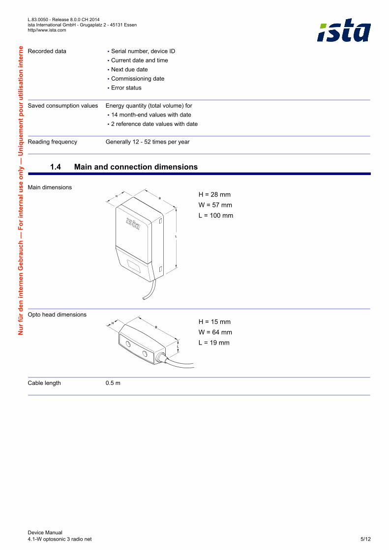
1.4 Main and connection dimensions
Main dimensionsH = 28 mm
W = 57 mm
L = 100 mm
Opto head dimensionsH = 15 mm
W = 64 mm
L = 19 mm
Cable length 0.5 m
Device Manual4.1-W optosonic 3 radio net 5/12
Page 6
L.83.0050 - Release 8.0.0 CH 2014ista International GmbH - Grugaplatz 2 - 45131 Essen
http://www.ista.com
Nu
r fü
r d
en
inte
rne
n G
eb
rau
ch —
Fo
r in
tern
al u
se o
nly
— U
niq
uem
en
t p
ou
r u
tili
sat
ion
inte
rne
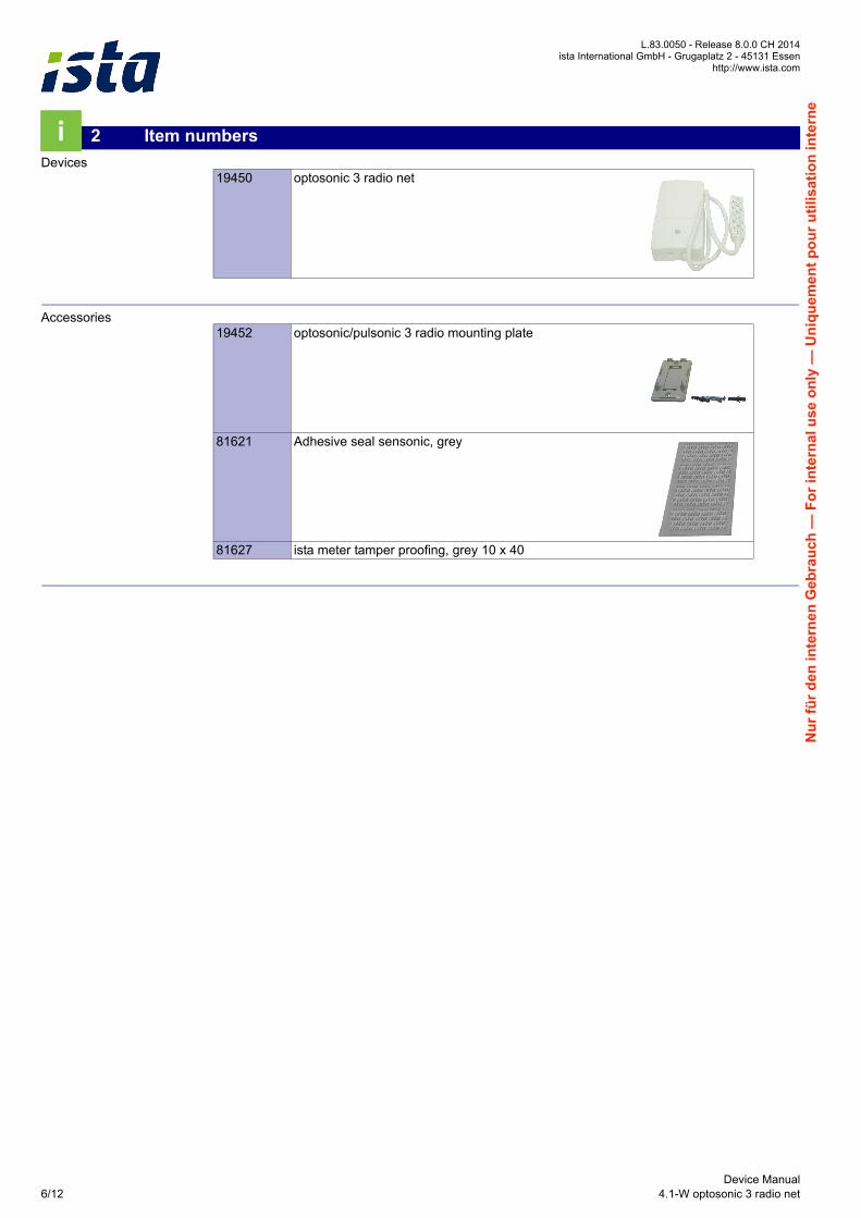
Devices
Accessories
2 Item numbers
19450 optosonic 3 radio net
19452 optosonic/pulsonic 3 radio mounting plate
81621 Adhesive seal sensonic, grey
81627 ista meter tamper proofing, grey 10 x 40
Device Manual6/12 4.1-W optosonic 3 radio net
Page 7
L.83.0050 - Release 8.0.0 CH 2014ista International GmbH - Grugaplatz 2 - 45131 Essenhttp//www.ista.com
Nu
r fü
r d
en
inte
rne
n G
eb
rau
ch —
Fo
r in
tern
al u
se
on
ly —
Un
iqu
emen
t p
ou
r u
tili
sa
tio
n in
tern
e
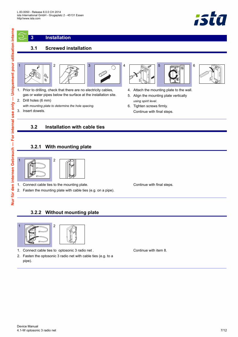
3.1 Screwed installation
1. Prior to drilling, check that there are no electricity cables, gas or water pipes below the surface at the installation site.
2. Drill holes (6 mm)
with mounting plate to determine the hole spacing.3. Insert dowels.
4. Attach the mounting plate to the wall.
5. Align the mounting plate vertically
using spirit level.6. Tighten screws firmly.
Continue with final steps.
3.2 Installation with cable ties
3.2.1 With mounting plate
1. Connect cable ties to the mounting plate.
2. Fasten the mounting plate with cable ties (e.g. on a pipe).
Continue with final steps.
3.2.2 Without mounting plate
1. Connect cable ties to optosonic 3 radio net .
2. Fasten the optosonic 3 radio net with cable ties (e.g. to a pipe).
Continue with item 8.
3 Installation
1 2 3 4 5 6
1 2
1 2
Device Manual4.1-W optosonic 3 radio net 7/12
Page 8
L.83.0050 - Release 8.0.0 CH 2014ista International GmbH - Grugaplatz 2 - 45131 Essen
http://www.ista.com
Nu
r fü
r d
en
inte
rne
n G
eb
rau
ch —
Fo
r in
tern
al u
se o
nly
— U
niq
uem
en
t p
ou
r u
tili
sat
ion
inte
rne
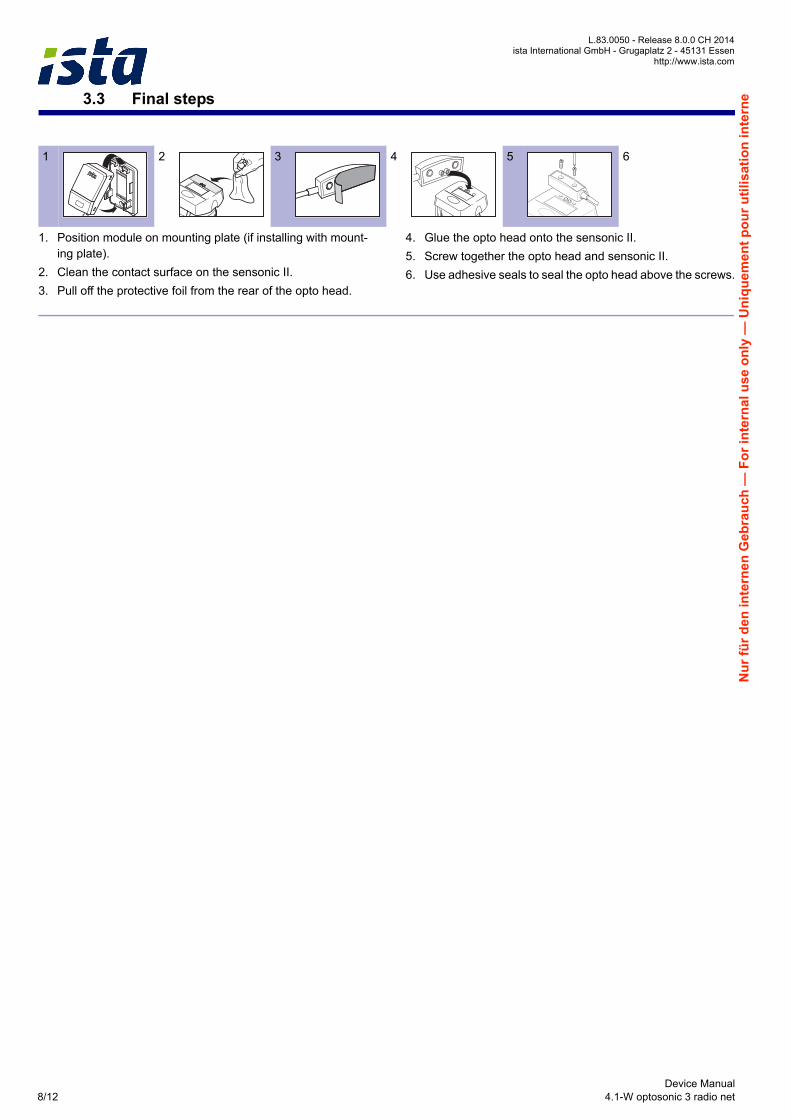
3.3 Final steps
1. Position module on mounting plate (if installing with mount-ing plate).
2. Clean the contact surface on the sensonic II.
3. Pull off the protective foil from the rear of the opto head.
4. Glue the opto head onto the sensonic II.
5. Screw together the opto head and sensonic II.
6. Use adhesive seals to seal the opto head above the screws.
1 2 3 4 5 6
Device Manual8/12 4.1-W optosonic 3 radio net
Page 9
L.83.0050 - Release 8.0.0 CH 2014ista International GmbH - Grugaplatz 2 - 45131 Essenhttp//www.ista.com
Nu
r fü
r d
en
inte
rne
n G
eb
rau
ch —
Fo
r in
tern
al u
se
on
ly —
Un
iqu
emen
t p
ou
r u
tili
sa
tio
n in
tern
e
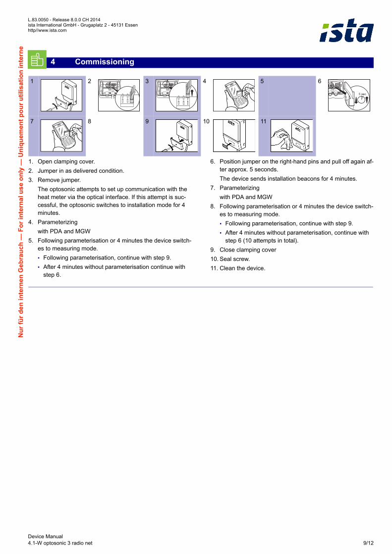
1. Open clamping cover.
2. Jumper in as delivered condition.
3. Remove jumper.
The optosonic attempts to set up communication with the heat meter via the optical interface. If this attempt is suc-cessful, the optosonic switches to installation mode for 4 minutes.
4. Parameterizing
with PDA and MGW
5. Following parameterisation or 4 minutes the device switch-es to measuring mode.
▪ Following parameterisation, continue with step 9.
▪ After 4 minutes without parameterisation continue with step 6.
6. Position jumper on the right-hand pins and pull off again af-ter approx. 5 seconds.
The device sends installation beacons for 4 minutes.
7. Parameterizing
with PDA and MGW
8. Following parameterisation or 4 minutes the device switch-es to measuring mode.
▪ Following parameterisation, continue with step 9.
▪ After 4 minutes without parameterisation, continue with step 6 (10 attempts in total).
9. Close clamping cover
10. Seal screw.
11. Clean the device.
4 Commissioning
1 2 3 4 5 6
7 8 9 10 11
Device Manual4.1-W optosonic 3 radio net 9/12
Page 10
L.83.0050 - Release 8.0.0 CH 2014ista International GmbH - Grugaplatz 2 - 45131 Essen
http://www.ista.com
Nu
r fü
r d
en
inte
rne
n G
eb
rau
ch —
Fo
r in
tern
al u
se o
nly
— U
niq
uem
en
t p
ou
r u
tili
sat
ion
inte
rne
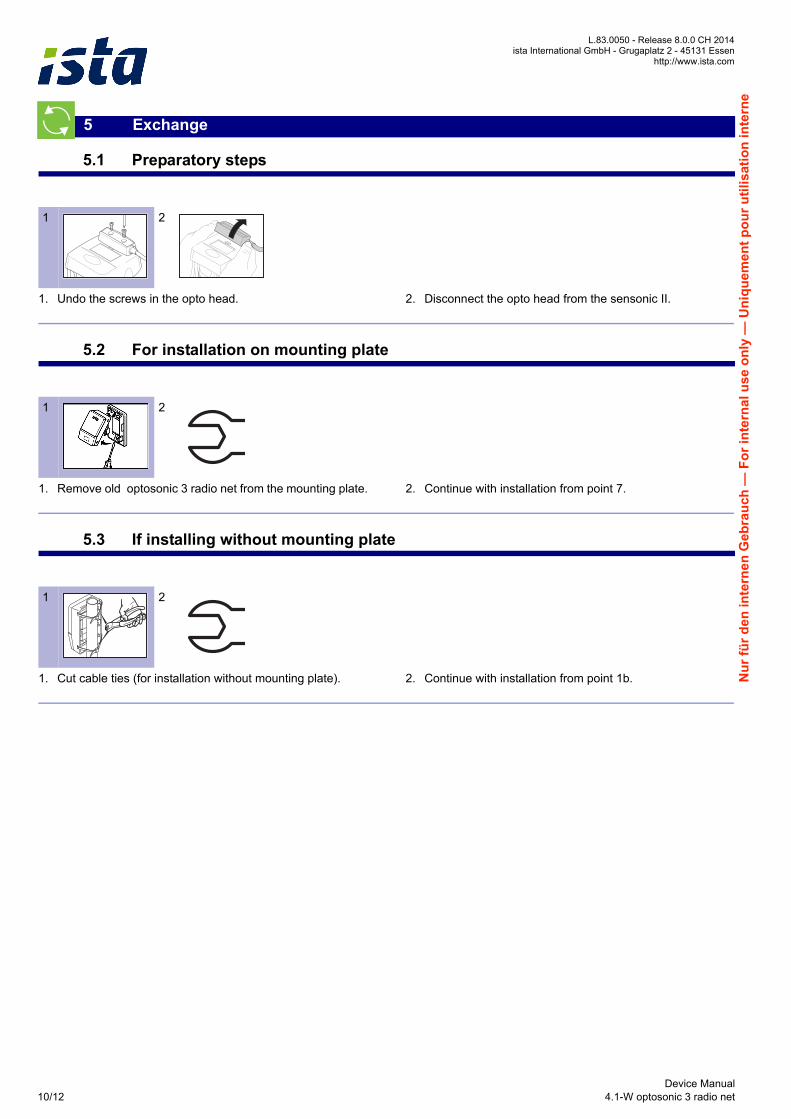
5.1 Preparatory steps
1. Undo the screws in the opto head. 2. Disconnect the opto head from the sensonic II.
5.2 For installation on mounting plate
1. Remove old optosonic 3 radio net from the mounting plate. 2. Continue with installation from point 7.
5.3 If installing without mounting plate
1. Cut cable ties (for installation without mounting plate). 2. Continue with installation from point 1b.
5 Exchange
1 2
1 2
1 2
Device Manual10/12 4.1-W optosonic 3 radio net
Page 11
L.83.0050 - Release 8.0.0 CH 2014ista International GmbH - Grugaplatz 2 - 45131 Essenhttp//www.ista.com
Nu
r fü
r d
en
inte
rne
n G
eb
rau
ch —
Fo
r in
tern
al u
se
on
ly —
Un
iqu
emen
t p
ou
r u
tili
sa
tio
n in
tern
e
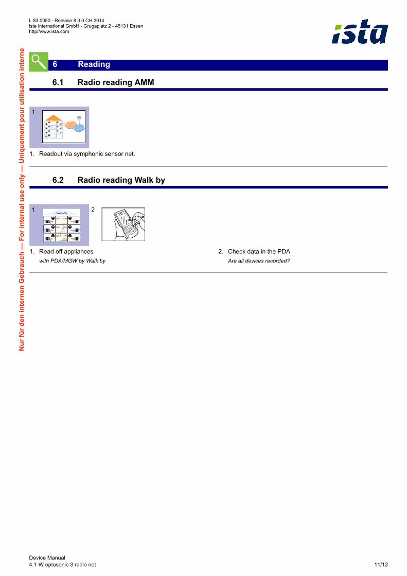
6.1 Radio reading AMM
1. Readout via symphonic sensor net.
6.2 Radio reading Walk by
1. Read off appliances
with PDA/MGW by Walk by
2. Check data in the PDA
Are all devices recorded?
6 Reading
1
1 2
Device Manual4.1-W optosonic 3 radio net 11/12
Page 12
L.83.0050 - Release 8.0.0 CH 2014ista International GmbH - Grugaplatz 2 - 45131 Essen
http://www.ista.com
Nu
r fü
r d
en
inte
rne
n G
eb
rau
ch —
Fo
r in
tern
al u
se o
nly
— U
niq
uem
en
t p
ou
r u
tili
sat
ion
inte
rne
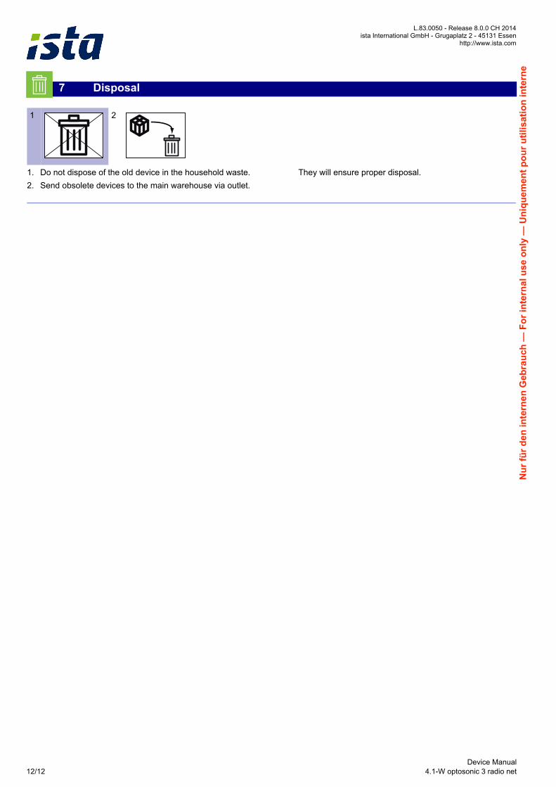
1. Do not dispose of the old device in the household waste.
2. Send obsolete devices to the main warehouse via outlet.
They will ensure proper disposal.
7 Disposal
1 2
Device Manual12/12 4.1-W optosonic 3 radio net