13
Device: PLT-2001 This document Version: 1 For hardware Version: 1 For firmware Version: 5.00 Date: 9 May 2014 Description: LED Matrix Display Driver board
| Date post: | 10-Nov-2018 |
| Category: |
Documents |
| Upload: | phungthuan |
| View: | 215 times |
| Download: | 0 times |
Device: PLT-2001
This document Version: 1
For hardware Version: 1
For firmware Version: 5.00
Date: 9 May 2014
Description: LED Matrix Display Driver board
PLT-2001v1 datasheet – Page 2
www.embeddedadventures.com
Contents
Introduction......................................................................................................... 4
Features .............................................................................................................. 4
Hackability ........................................................................................................... 4
Construction ........................................................................................................ 4
Connections ......................................................................................................... 5
Power ................................................................................................................. 5
Setup .................................................................................................................. 5
Operation ............................................................................................................ 6
Commands .......................................................................................................... 6
clear ................................................................................................................ 7
pixel ................................................................................................................ 7
line .................................................................................................................. 7
rect .................................................................................................................. 7
circle ................................................................................................................ 7
circlef ............................................................................................................... 8
circle2 .............................................................................................................. 8
font ................................................................................................................. 8
text .................................................................................................................. 9
textv ................................................................................................................ 9
scroll ................................................................................................................ 9
scrollspeed ....................................................................................................... 9
scrollloop n ...................................................................................................... 9
paint ................................................................................................................ 9
title ................................................................................................................ 10
enableactive ................................................................................................... 10
Tips and tricks ................................................................................................... 10
Other panels ...................................................................................................... 11
Schematic .......................................................................................................... 11
General circuit ................................................................................................ 11
PLT-2001v1 datasheet – Page 3
www.embeddedadventures.com
Connections ................................................................................................... 12
Power ............................................................................................................ 12
PCB ................................................................................................................... 13
What next? ........................................................................................................ 13
Versions ............................................................................................................ 13
PLT-2001v1 datasheet – Page 4
www.embeddedadventures.com
Introduction
The PLT-2001v1 is a driver board designed to drive dynamically-scanned LED matrix
displays (LED display panels) such as the LDP-3208S, LDP-8008, LDP-6416 and LDP-
6432 from Embedded Adventures. Other panels that have similar pin-outs will work
as well. Other panels that have different pin-outs but work the same way, will work
with a little jumper wiring.
You don’t need to know anything about the microcontroller on board to use the driver
board however – it takes simple commands over the TTL serial port to enable rich
graphical displays on common LED matrix display panels. Of course, if you want to,
you can completely hack the firmware to change it in any way you like, but this is not
necessary for normal operation.
Features
The PLT-2001 is designed to make it easy to interface to LED matrix displays. These
displays require constant updating which consumes microcontroller CPU. This driver
board allows graphical and text functions to be displayed through simple serial
commands.
Hackability
The PLT-2001 is 100% hackable.
At Embedded Adventures, we believe you have the most fun when you have the most
control over your hardware. For the PLT-2001 we provide a datasheet, complete
schematic and complete source code. After that, it’s all up to you. We’d love to hear
about the projects you’re using it for – send us information and photos to
Construction
The PLT-2001v1 can be back-pack connected to LDP-8008 displays by soldering an
8x2 0.1” female connector on the underside of the board (so the pins are soldered on
top). The holes on the PLT-2001v1 are designed to match the holes on the LDP-8008.
It can also be back-pack connected to LDP-6416 or LDP-6432, or alternatively a male
connector inserted into the top of the board (and soldered on the back of the boards)
and an IDC cable can be used to connect to the display.
For power, the PLT-2001 requires 5V and ground connections. Solder the terminal
connectors on the board for easy screw connections, or simply power it through the
5V pin on the serial header.
PLT-2001v1 datasheet – Page 5
www.embeddedadventures.com
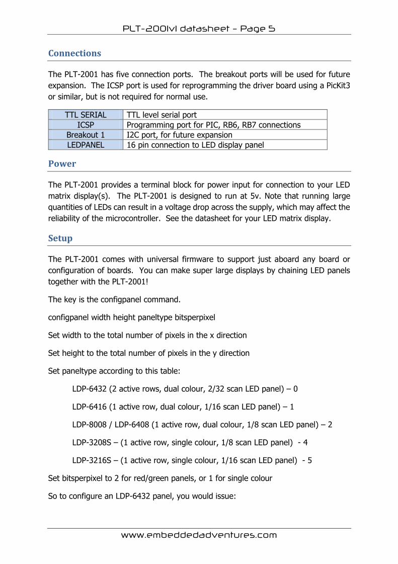
Connections
The PLT-2001 has five connection ports. The breakout ports will be used for future
expansion. The ICSP port is used for reprogramming the driver board using a PicKit3
or similar, but is not required for normal use.
TTL SERIAL TTL level serial port
ICSP Programming port for PIC, RB6, RB7 connections
Breakout 1 I2C port, for future expansion
LEDPANEL 16 pin connection to LED display panel
Power
The PLT-2001 provides a terminal block for power input for connection to your LED
matrix display(s). The PLT-2001 is designed to run at 5v. Note that running large
quantities of LEDs can result in a voltage drop across the supply, which may affect the
reliability of the microcontroller. See the datasheet for your LED matrix display.
Setup
The PLT-2001 comes with universal firmware to support just aboard any board or
configuration of boards. You can make super large displays by chaining LED panels
together with the PLT-2001!
The key is the configpanel command.
configpanel width height paneltype bitsperpixel
Set width to the total number of pixels in the x direction
Set height to the total number of pixels in the y direction
Set paneltype according to this table:
LDP-6432 (2 active rows, dual colour, 2/32 scan LED panel) – 0
LDP-6416 (1 active row, dual colour, 1/16 scan LED panel) – 1
LDP-8008 / LDP-6408 (1 active row, dual colour, 1/8 scan LED panel) – 2
LDP-3208S – (1 active row, single colour, 1/8 scan LED panel) - 4
LDP-3216S – (1 active row, single colour, 1/16 scan LED panel) - 5
Set bitsperpixel to 2 for red/green panels, or 1 for single colour
So to configure an LDP-6432 panel, you would issue:
PLT-2001v1 datasheet – Page 6
www.embeddedadventures.com
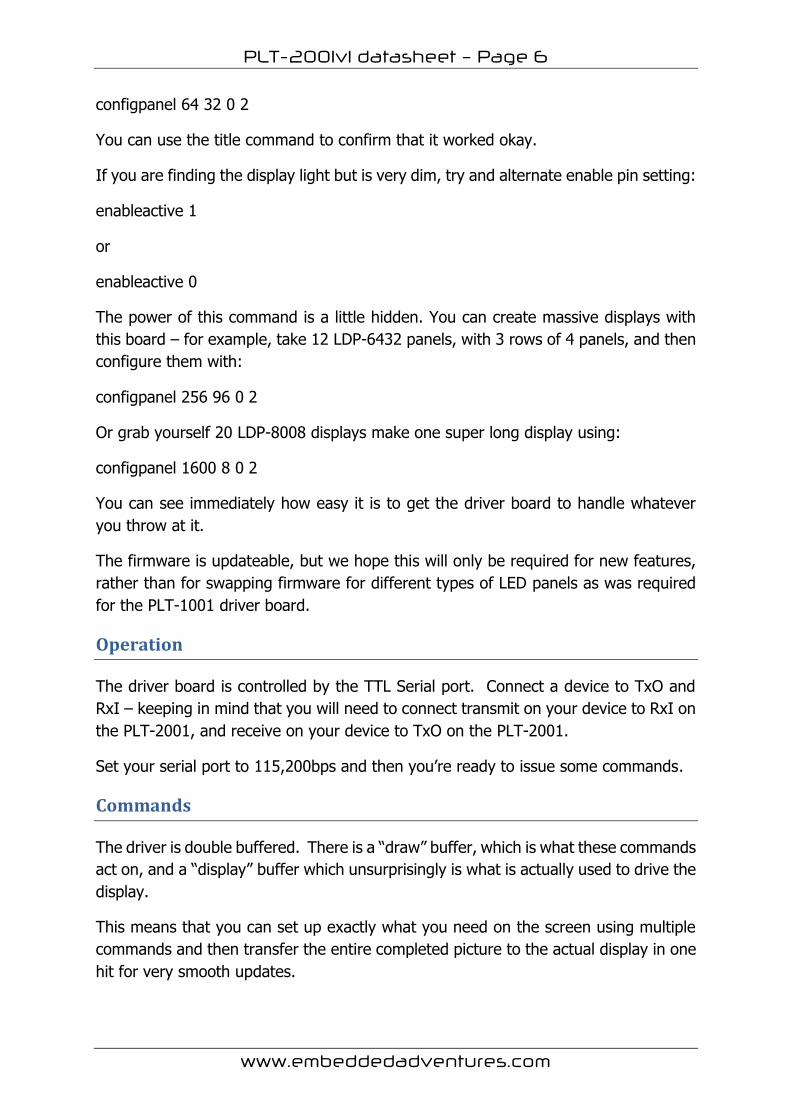
configpanel 64 32 0 2
You can use the title command to confirm that it worked okay.
If you are finding the display light but is very dim, try and alternate enable pin setting:
enableactive 1
or
enableactive 0
The power of this command is a little hidden. You can create massive displays with
this board – for example, take 12 LDP-6432 panels, with 3 rows of 4 panels, and then
configure them with:
configpanel 256 96 0 2
Or grab yourself 20 LDP-8008 displays make one super long display using:
configpanel 1600 8 0 2
You can see immediately how easy it is to get the driver board to handle whatever
you throw at it.
The firmware is updateable, but we hope this will only be required for new features,
rather than for swapping firmware for different types of LED panels as was required
for the PLT-1001 driver board.
Operation
The driver board is controlled by the TTL Serial port. Connect a device to TxO and
RxI – keeping in mind that you will need to connect transmit on your device to RxI on
the PLT-2001, and receive on your device to TxO on the PLT-2001.
Set your serial port to 115,200bps and then you’re ready to issue some commands.
Commands
The driver is double buffered. There is a “draw” buffer, which is what these commands
act on, and a “display” buffer which unsurprisingly is what is actually used to drive the
display.
This means that you can set up exactly what you need on the screen using multiple
commands and then transfer the entire completed picture to the actual display in one
hit for very smooth updates.

PLT-2001v1 datasheet – Page 7
www.embeddedadventures.com
The driver board comes with a collection of graphical and text commands. Each
command starts with a text word and ends with <ENTER> (ASCII character 13 –
which is \r if you are using a microcontroller to send commands).
Once you have sent all commands you need, send a paint command. Effectively the
paint command copies the draw buffer to the display buffer.
The exceptions to this are the scroll command, which doesn’t require paint, since it
updates the buffer automatically as the text moves across the display, and the title
command.
Parameters to the commands can be separated by commas or spaces.
Most LED matrix displays, at least the ones from Embedded Adventures, have one or
two pixel colours available – a single colour, or red and green, giving you black (colour
0), red (colour 1), green (colour 2), yellow/orange (colour 3).
clear
clear
Clear the display (all black pixels)
pixel
pixel colour x y
Set the pixel at position x, y to the specified colour. On LED matrix displays, x = 0 on
the left most column, and y = 0 on the top row.
line
line colour x1 y1 x2 y2
Draws a line between x1, y1 and x2, y2 in the specified colour.
rect
rect colour x y width height
Draws a rectangle with left, bottom corner x,y that is width wide and height high.
Keep in mind that x and y specifies the bottom left corner of the rectangle, so to fill a
64x32 display, issue: rect 1 0 31 64 32
circle
circle colour x_centre y_centre radius
Draws a circle centred at x_centre, y_centre in the specified radius and colour.
PLT-2001v1 datasheet – Page 8
www.embeddedadventures.com
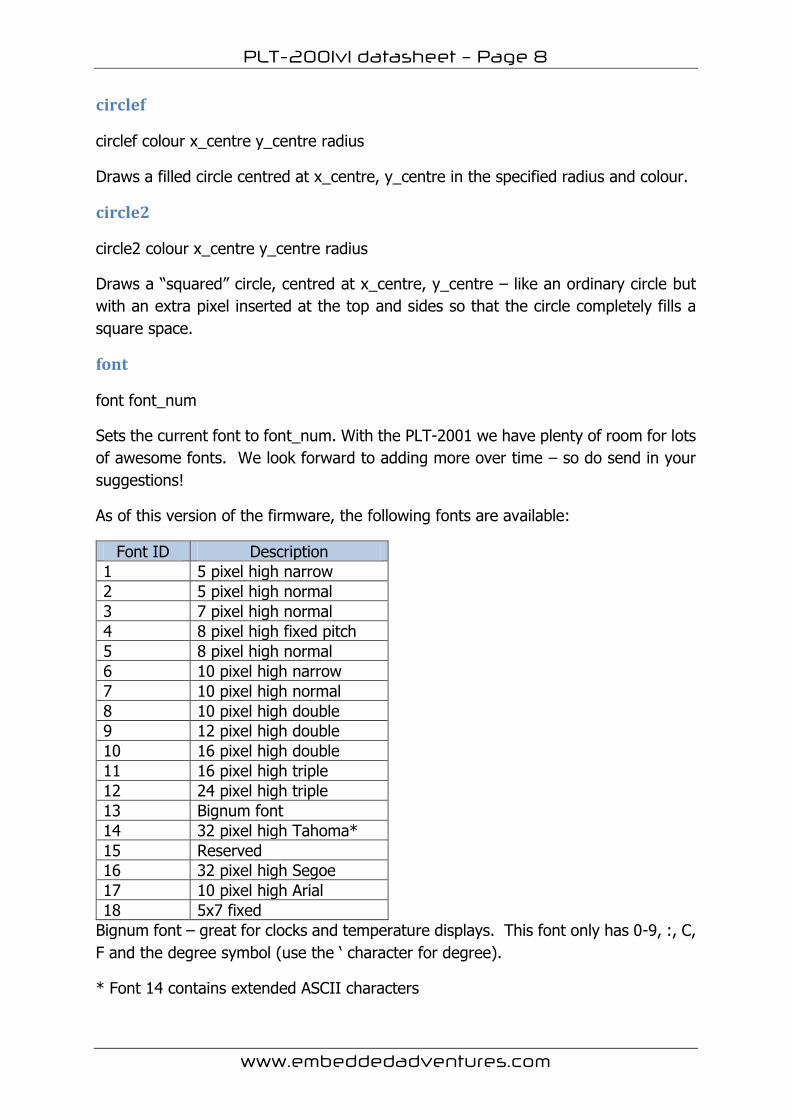
circlef
circlef colour x_centre y_centre radius
Draws a filled circle centred at x_centre, y_centre in the specified radius and colour.
circle2
circle2 colour x_centre y_centre radius
Draws a “squared” circle, centred at x_centre, y_centre – like an ordinary circle but
with an extra pixel inserted at the top and sides so that the circle completely fills a
square space.
font
font font_num
Sets the current font to font_num. With the PLT-2001 we have plenty of room for lots
of awesome fonts. We look forward to adding more over time – so do send in your
suggestions!
As of this version of the firmware, the following fonts are available:
Font ID Description
1 5 pixel high narrow
2 5 pixel high normal
3 7 pixel high normal
4 8 pixel high fixed pitch
5 8 pixel high normal
6 10 pixel high narrow
7 10 pixel high normal
8 10 pixel high double
9 12 pixel high double
10 16 pixel high double
11 16 pixel high triple
12 24 pixel high triple
13 Bignum font
14 32 pixel high Tahoma*
15 Reserved
16 32 pixel high Segoe
17 10 pixel high Arial
18 5x7 fixed
Bignum font – great for clocks and temperature displays. This font only has 0-9, :, C,
F and the degree symbol (use the ‘ character for degree).
* Font 14 contains extended ASCII characters
PLT-2001v1 datasheet – Page 9
www.embeddedadventures.com
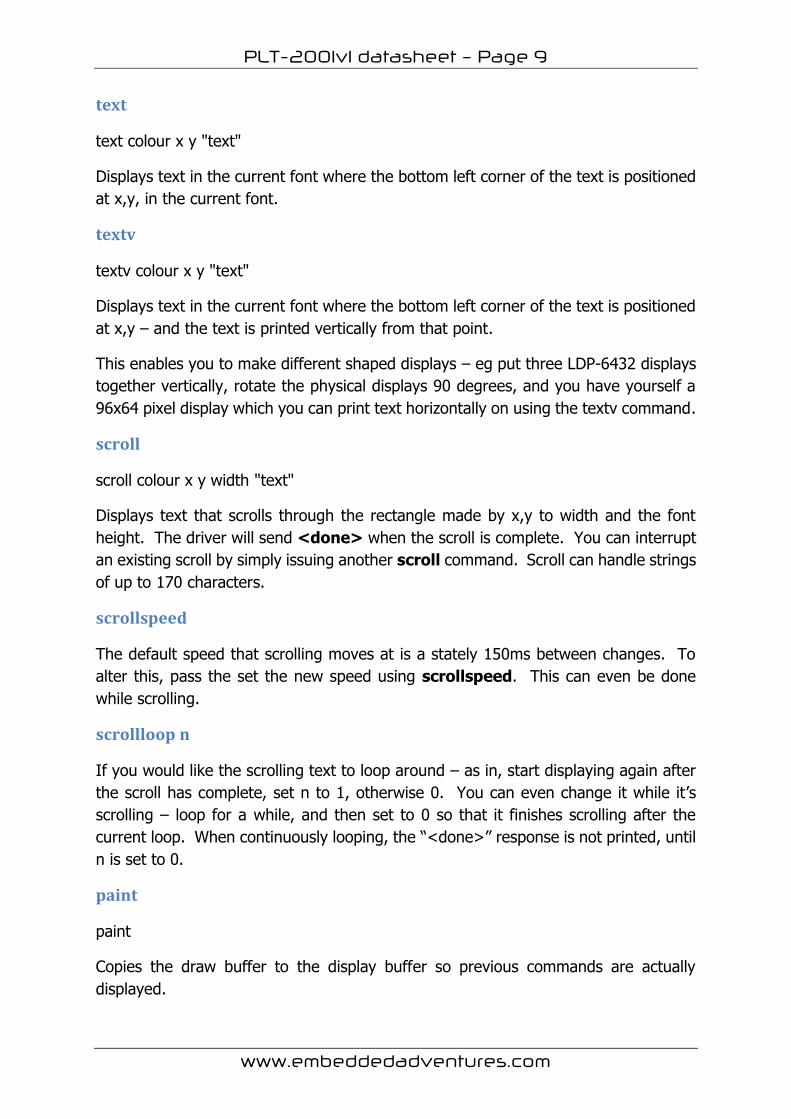
text
text colour x y "text"
Displays text in the current font where the bottom left corner of the text is positioned
at x,y, in the current font.
textv
textv colour x y "text"
Displays text in the current font where the bottom left corner of the text is positioned
at x,y – and the text is printed vertically from that point.
This enables you to make different shaped displays – eg put three LDP-6432 displays
together vertically, rotate the physical displays 90 degrees, and you have yourself a
96x64 pixel display which you can print text horizontally on using the textv command.
scroll
scroll colour x y width "text"
Displays text that scrolls through the rectangle made by x,y to width and the font
height. The driver will send <done> when the scroll is complete. You can interrupt
an existing scroll by simply issuing another scroll command. Scroll can handle strings
of up to 170 characters.
scrollspeed
The default speed that scrolling moves at is a stately 150ms between changes. To
alter this, pass the set the new speed using scrollspeed. This can even be done
while scrolling.
scrollloop n
If you would like the scrolling text to loop around – as in, start displaying again after
the scroll has complete, set n to 1, otherwise 0. You can even change it while it’s
scrolling – loop for a while, and then set to 0 so that it finishes scrolling after the
current loop. When continuously looping, the “<done>” response is not printed, until
n is set to 0.
paint
paint
Copies the draw buffer to the display buffer so previous commands are actually
displayed.
PLT-2001v1 datasheet – Page 10
www.embeddedadventures.com
title
The title command is a great way of testing your display. Using whatever resolution
is available, it will draw a boarder around the outside, and show you the version of
the firmware among other things. This enables you to see which display is which and
see which way around the displays are orientated – the text will always be in the top-
most or left-most display.
enableactive
The Enable line on LED matrix displays can be a different polarity on different displays.
All the displays you use in one daisy chain must be the same type.
For a display that is active low, issue the command:
enableactive 0
For a display that is active high, issue the command:
enableactive 1
It won’t harm your display either way, but if you’re getting nothing displayed at all, or
it is quite feint, try the opposite polarity.
Tips and tricks
I’m sending commands but nothing is displayed!
Check the power connections. Be careful when hooking up the board since reversing
the connections will damage LED matrix displays.
Make sure you send a paint command after you send commands. Try the title
command. It’s a great first step to see that everything is working.
Check that your panel has the same pin-out as the PLT-2001 – it’s called “HUB08”, a
semi-standard for LED panels.
And if your display is either blank or you can see pixels only faintly, then you probably
need to try the enableactive command to set the ENable line correctly.
I’m sending commands and there’s crazy stuff being displayed!
Actually this used to be a problem with the PLT-1001 if you sent it random commands
that drew outside of the boundary of the current panel. With the PLT-2001, you can
happily draw outside the screen and it will simply clip your command.
Red displays okay but green is very faint and orange/yellow is more red than
orange/yellow.
PLT-2001v1 datasheet – Page 11
www.embeddedadventures.com
You probably haven’t powered the displays with their 5V and GND connections and
your display is leaching current from the serial connection.
Other panels
If your LED panel has a different pin-out to the standard set, it is a simple matter of
connecting the correct pins to the LED Panel connection on the PLT-2001. In this
case, you may find it easier to use a male connector on the top of the board so female
jumpers can be used.
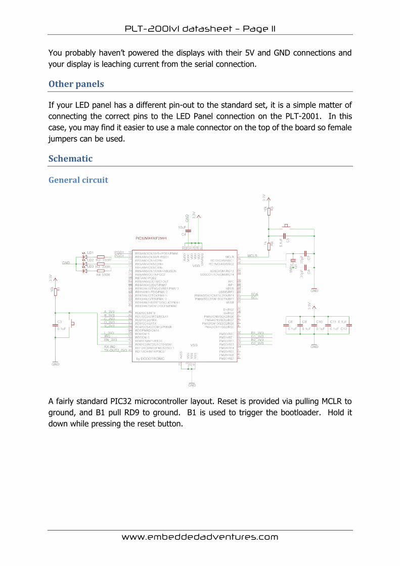
Schematic
General circuit
A fairly standard PIC32 microcontroller layout. Reset is provided via pulling MCLR to
ground, and B1 pull RD9 to ground. B1 is used to trigger the bootloader. Hold it
down while pressing the reset button.
PLT-2001v1 datasheet – Page 12
www.embeddedadventures.com
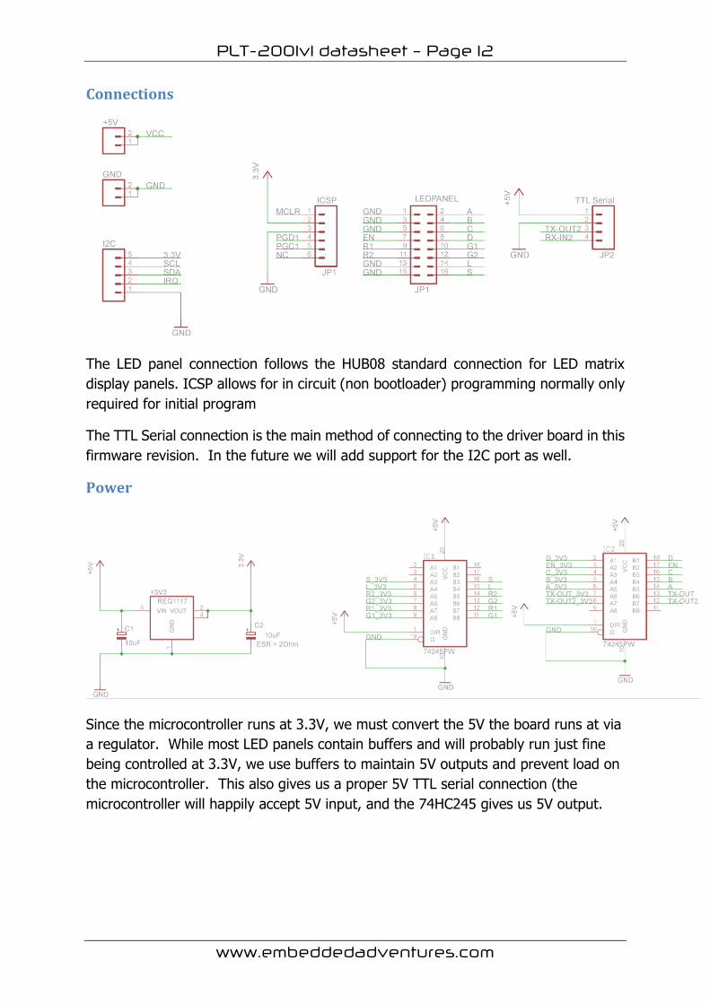
Connections
The LED panel connection follows the HUB08 standard connection for LED matrix
display panels. ICSP allows for in circuit (non bootloader) programming normally only
required for initial program
The TTL Serial connection is the main method of connecting to the driver board in this
firmware revision. In the future we will add support for the I2C port as well.
Power
Since the microcontroller runs at 3.3V, we must convert the 5V the board runs at via
a regulator. While most LED panels contain buffers and will probably run just fine
being controlled at 3.3V, we use buffers to maintain 5V outputs and prevent load on
the microcontroller. This also gives us a proper 5V TTL serial connection (the
microcontroller will happily accept 5V input, and the 74HC245 gives us 5V output.
PLT-2001v1 datasheet – Page 13
www.embeddedadventures.com
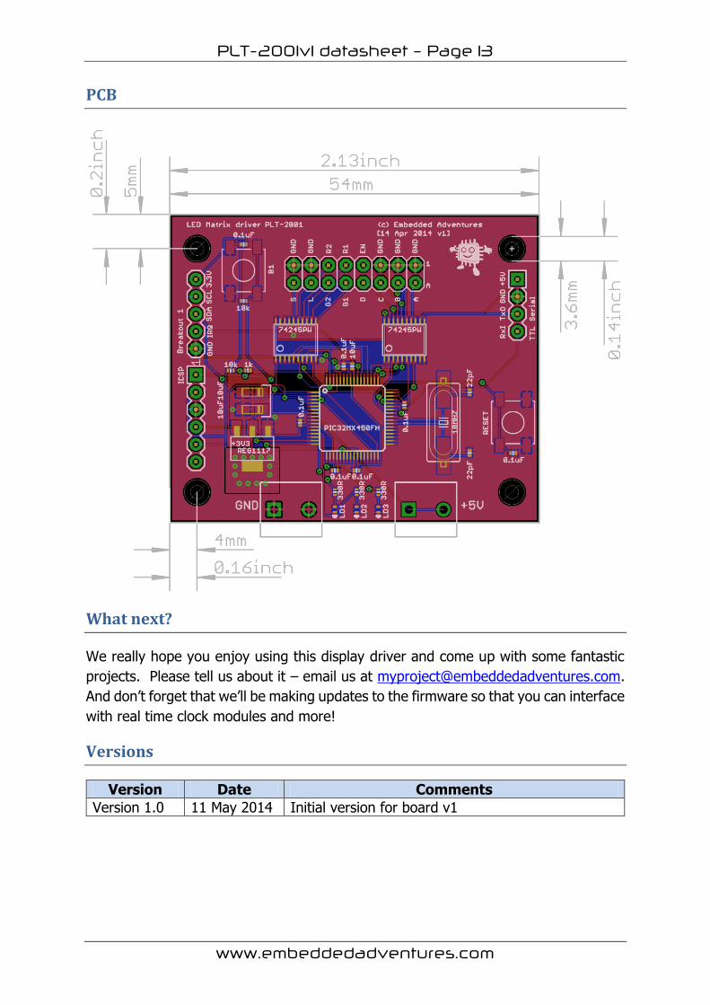
PCB
What next?
We really hope you enjoy using this display driver and come up with some fantastic
projects. Please tell us about it – email us at [email protected].
And don’t forget that we’ll be making updates to the firmware so that you can interface
with real time clock modules and more!
Versions
Version Date Comments
Version 1.0 11 May 2014 Initial version for board v1


