68
DeviceNet Product Overview
DeviceNet Product Overview


Publication DN-2.5 - February 1998 1
DeviceNet Product OverviewIntroduction
What’s in This Overview? Rockwell Automation DeviceNet™ products provide cost-effective solutions to your automation application needs. Read this product overview to find out about our line of DeviceNet products.
Product SeeGlobal Technical Services DeviceNet Customer Training page 22
Physical Media page 23
Series 9000 Photoelectric Sensor page 31
RediSTATION Operator Interface page 32
AdaptaScan Bar Code Reader page 33
Smart Speed Controller (SSC) - Bulletin 160 AC Drive page 34
DeviceNet Communication Module for Drives and Power Products page 35
Smart Motro Protector (SMP-3) Solid-State Relay page 36
SMC Dialog Plus II Controller for the DeviceNet Network page 37
1305 AC Drive, 1336 PLUS II AC Drive, 1336 IMPACT™ AC Drive, and 1397 DC Drive
page 38
1557 Medium Voltage Drive page 39
1394 Digital AC Multi-Axis Motion Control System page 40
GV3000 Drive and FlexPak3000 Drive page 41
Dodge EZLINK Bearing Monitor page 42
DeviceLink I/O page 43
ArmorBlock I/O Blocks page 44
DeviceNet FLEX I/O Adapter page 45
DeviceNet Scanner for 1771 Chassis page 46
DeviceNet Scanner for SLC Chassis page 47
DTAM Plus Operator Interface and DTAM Micro Operator Interface (2707 Series)
page 48
DeviceNet PCI Interface Card page 49
DeviceView Hand-Held Configurator page 50
PCMCIA Card Interface page 51
RS-232 Personal Computer Interface page 52
Open Controller (1747-OC) page 53
DeviceNet Power Supply (1784-DNPS) page 54
DeviceNet Network Interface for MicroLogix, SLC and PLC DeviceNet Connectivity
page 55
PanelView 550-1400 (2711 Series) page 56
DeviceNet Starter Auxiliary (DSA) page 57
DeviceNet Bridge for ControlLogix Gateway page 58
DeviceNet Example Code (9240-DNEXP) page 59
DeviceNet Master Library page 60
DeviceNet Slave Development Tools (9240-DNSDT) page 61
Controlware Software for Embedded Applications page 62
DeviceNet Monitor Tool (9240-MON16) page 63
RSServer for DeviceNet page 64

2 Publication DN-2.5 - February 1998
DeviceNet Product OverviewIntroduction
About the DeviceNet Network The DeviceNet network connects low-level devices directly to plant-floor controllers without the need to hard-wire them to I/O modules. More than 300 vendors world-wide actively support the Open DeviceNet Vendor Association’s (ODVA) CAN-based network.
This 64-node, multidrop network allows you to use a single cable to interface devices up to 500m (1641ft) and beyond to your programmable controller rather than wiring each device to an I/O chassis. This all adds up to reduced wiring costs and a quicker installation setup.
"Intelligent" devices now can provide diagnostics – including predictive failure that can be used to reduce system downtime.
Why is the DeviceNet Network Betterthan Other Network Options?
The DeviceNet network is based on the Producer/Consumernetwork model, the latest in networking technology. Producer/Consumer makes control data accessible to every component of the operation simultaneously, making more efficient use of network bandwidth.
Producer/Consumer can dramatically reduce network traffic as it allows for change-of-state messaging, giving you faster response, and cyclic messaging, giving you greater determinism. Peer-to-peer messaging allows for data and status information exchange between devices. These benefits—faster response, greater determinism, increased flexibility/optimization—all yield higher productivity.

Publication DN-2.5 - February 1998 3
DeviceNet Product OverviewIntroduction
Combining DeviceNet Features andRockwell Automation Innovation
The DeviceNet network is a cost-effective solution to low-level device networking and provides access to intelligence present in those devices. Rockwell Automation continues to bring you innovative solutions based on the most current technology. Accordingly, we bring you DeviceNet products that give you the ability to:
• know a Series 9000 photoelectric sensor is losing margin (possi-bly because of dust accumulation on the lens) before it fails to detect an object
• share look-up tables and I/O status among multiple AdaptaScan™bar code readers
• monitor motor current draw, phase balance, and thermal capacity with the SMP-3™ solid-state overload relay
• record historical bearing temperature and vibration with the EZLINK™ bearing monitor
• reduce your installation costs by decreasing the number of physical taps on the DeviceNet trunk line with DevicePort™ taps or DeviceBox™ taps
• eliminate additional enclosures and reduce installation time with ArmorBlock™ I/O blocks
• connect up to 128 discrete points using the FLEX I/O™ system and a single 1794-ADN adapter
We designed our automation architecture to include information networks, control networks, and device networks. The DeviceNet network fits easily into this architecture at the device level, making it simple for you to add Rockwell Automation DeviceNet products to your existing control system.
1784-PCD PCMCIA card
personal computer with DeviceNetManager software
1771-SDN scanner
1747-SDN scanner
Series 9000 photoelectric sensor
RediSTATION operator interface
AdaptaScan bar code reader
1336 PLUS II drive
1305 drive
1336 IMPACT drive
GV3000 drive
EZLINK bearing monitor
FlexPak 3000 drive
motor starter with SMP-3 overload relay
SSC Bulletin
160
SMC Dialog Plus DeviceLink I/O
with limitswitch
FLEX I/O
ArmorBlock I/O module
DTAM Micro or Plus
DeviceView hand-held configurator
20455-M
L2S
L1R
L3T
BRÐ
BR+
1 2 3 4 5 6 7 8 9 10 11
T2V
TIU
T3W
ÐDC
+DC
FAULTREADY
DeviceNet
COMM
ª

4 Publication DN-2.5 - February 1998
DeviceNet Product OverviewIntroduction
Business Computing Systems
Computing platforms with DOS, Windows, Windows NT, OpenVMS, HP-UX, OSF/1, AIX, and Solaris operating systems
Information Layer (TCP/IP over Ethernet Network)
Information Processors
Control coprocessor - or Information processor with PCMCIA Ethernet adapter working with a ControlNet PLC-5 processor
Communication Products
Ethernet interface module with ControlNet PLC-5 or Ethernet PLC-5 processor
ControlLogix Gateway
Personal computer with serial connection to 1770-KFC interaface
Personal computer with 1784-KTCX interface
Control Layer (ControlNet Network)
Programmable Controllers
PLC-5 family processors
SLC 500 processors
Drives Systems
Data Highway Plus
Universal Remote I/O
DH-485direct connect to MicroLogix to DNET
Input/Output
1771 I/O1746 I/O
FLEX I/O
Programming Support Tools
Rockwell Software programming software
DeviceNet PCMCIA card DeviceNetManager software
Operator Interfaces
PanelView 1200e operator terminal
PanelView 1400e operator terminal
Device Layer (DeviceNet Network)
I/O Blocks/Modules
1792 ArmorBlock I/O blocks
FLEX I/O
Automatic Indentification
AdaptaScan bar code reader
Intelligent Sensors
Series 9000 photoelectric sensors
Motor Starters and Protection
NEMA or IEC motor starter with SMP-3 overlay relay
SMC Dialog Plus soft starter
AC & DC Drives
1336 PLUS II AC drive
1305 AC drive
Operator Interface (dedicated)
DTAM Plus operator interface
DTAM Micro operator interface
RediSTATION operator interfaces
19617-M
GV3000 AC drive

Publication DN-2.5 - February 1998 5
DeviceNet Product OverviewIntroduction
Integrating DeviceNetProducts with your Existing
Rockwell Automation Architecture
As a full-line supplier, we know that the function and cost of an integrated control system are dictated by how easily and effectively you can combine system components.
The DeviceNet network was designed to meet your needs. Rockwell Automation DeviceNet products increase flexibility and efficiency in your control system.
Integrate the industry’s fully open network with Allen-Bradley PLC®
scanners, SLC™ scanners, Series 9000 photoelectric sensors, and ac and dc drives, along with Reliance ac and dc drives and many other control products. Our DeviceNet products take advantage of this exciting new technology and provide access to your existing Rockwell Automation architecture.
Whether you’re using the ControlNet™ network, DH+™ network, or Ethernet™ network, PLC processors, SLC processors, or other processors, Rockwell Automation DeviceNet products are easily integrated to help you link the plant floor with the rest of your control system.
Related PublicationsTitle Publication NumberDeviceNet System Overview DN-2.15
DeviceNet Cable System Planning and Installation Manual DN-6.7.2

6 Publication DN-2.5 - February 1998
DeviceNet Product OverviewIntroduction
Rely on Rockwell Automation Qualityand World-Class Support
We have helped numerous customers around the world achieve their manufacturing goals. For assistance with Rockwell Automation DeviceNet products, call your local distributor or sales office.
Our support network offers complete system integration and support services including application engineering, installation supervision, system startup, training, field service, and ongoing product support.
We’re global because we’re local to you.
You can access a Rockwell Automation sales representative, appointed distributor, or authorized system integrator almost anywhere around the world. Perhaps that’s why Rockwell Automation is the preferred supplier of automation controls in the industry.

Publication DN-2.5 - February 1998 7
DeviceNet Product OverviewDeviceNet Technical Overview
What is DeviceNet? DeviceNet is a low-cost communications link to connect industrial devices (such as limit switches, photoelectric sensors, valve manifolds, motor starters, process sensors, bar code readers, variable frequency drives, panel displays and operator interfaces) to a network and eliminate expensive hardwiring.
The direct connectivity provides improved communication between devices as well as important device-level diagnostics not easily accessible or available through hardwired I/O interfaces,
DeviceNet is a simple, networking solution that reduces the cost and time to wire and install industrial automation devices, while providing interchangeability of like components from multiple vendors.
DeviceNet is an open network standard. The specification and protocol are open—vendors are not required to purchase hardware, software, or licensing rights to connect devices to a system. Anyone may obtain the DeviceNet Specification from the Open DeviceNet Vendor Association, Inc. (ODVA) for a nominal reproduction charge. Any company that manufactures DeviceNet products may join ODVA and participate in technical working groups that are developing enhancements to the DeviceNet Specification.
Buyers of the DeviceNet Specification receive an unlimited, royalty-free licence to develop DeviceNet products. Companies looking for assistance may purchase sample code that eases their implementation, development toolkits, and development services from many sources. The key hardware components are available from the largest worldwide suppliers of semiconductors.
Why the DeviceNet Communication Link?
For years the process industry has been attempting to develop a single, open standard to address all kinds of field devices. The original scope of their standards effort was aimed at replacing the 4-20 mA standard with a single digital standard. As the scope increased to address complex and sophisticated services (such as high data rate communications between controllers, time synchronization of large numbers of devices scanning at very high speeds), the development of a single standard became delayed.

8 Publication DN-2.5 - February 1998
DeviceNet Product OverviewDeviceNet Technical Overview
At the same time, the cost of communication technology has dropped considerably in recent years, making it cost-effective to connect simple devices never considered for SP50 fieldbus directly to a network. Such a standard for simple devices requires the same level of interchangeability as exists for 120/220 VAC and 24 VDX discrete, hardwired I/O. DeviceNet allows the interchangeability of simple devices while making interconnectivity for more complex devices possible. In addition to reading the state of discrete devices, DeviceNet provides the capability to report temperatures, to read the load current in a motor starter, to change the deceleration rate of drives, or to count the number of packages that have passed on a conveyor in the previous hour.
Controller Area Network (CAN) is the Key to Low Cost Products
The DeviceNet communication link is based on a broadcast-oriented, communications protocol—the Controller Area Network (CAN). The CAN protocol was originally developed by BOSCH for the European automatic market for replacing expensive, wire harnesses with low-cost network cable on automobiles. As a result, the CAN protocol has fast response and high reliability for applications as demanding as control of anti-lock brakes and air-bags. Chips are available in a variety of packages with high temperature ratings and high noise immunity, attributes well suited for the industrial automation market as well.
DeviceNet Features and FunctionalityNetwork Size Up to 64 nodes
Network length Selectable end-to-end network distance varies with speed
Baud Rate Distance125 Kbps 500 m (1,640 ft.)
250 Kbps 250 m (820 ft.)
500 Kbps 100 m (328 ft.)
Data packets 0-8 bytes
Bus topology Linear (trunkline/dropline); power and signal on the same network cable
Bus addressing Peer-to-peer with Multi-Cast (one-to-many); Multi-Master and Master/slave special case; polled or change-of-state (exception-based)
System features Removal and replacement of devices from the network under power

Publication DN-2.5 - February 1998 9
DeviceNet Product OverviewDeviceNet Technical Overview
What is the DeviceNet Specification? The DeviceNet Specification defines a network communication system for moving data between elements of an industrial control system. The specification is divided into two volumes and defines the following elements:
Volume 1• DeviceNet Communication Protocol and Application (Layer 7 -
Application Layer)• CAN and its use in DeviceNet (Layer 2 - Data Link Layer)• DeviceNet Physical Layer and Media (Layer 1 - Physical Layer)
Volume 2• Device Profiles to obtain interoperability and interchangeability
among like products
CAN defines the syntax or form of the data movement. The DeviceNet application layer defines the semantics or meaning of the data moved.
Communication Protocol Features
• Peer-to-peer data exchange in which any DeviceNet product can produce and consume messages
• Master/slave operation defined as a proper subset of peer-to-peer• A DeviceNet product may behave as a client or a server or both• A DeviceNet network may have up to 64 Media Access control
Identifiers or MAC IDs (node addresses). Each node can support an infinite number of I/O. Typical I/O counts for pneumatic valve actuators are 16 or 32.
The Object Model
A DeviceNet node is modeled as a collection of Objects. An object provides an abstract representation of a particular component within a product. The realization of this abstract object model with a product is implementation dependent.
An Object Instance and an Object Class have Attributes (data), provide Services (methods or procedures), and implement Behaviors. Attributes, Instances, Class and Node Address are addressed by number.
DeviceNet Physical Layer Media The DeviceNet Specifications defines the allowable topologies and components. The specification also deals with system grounding, mixing thick and thin media, termination, and power distribution.
The basic trunkline-dropline topology provides separate twisted pair busses for both signal and power distribution. Thick or thin cable can be used for either trunklines or droplines. End-to-end network distance varies with data rate and cable size.
Figure 1 DeviceNet is an Application Layer Protocol (ISO Layer 7)
DeviceNet Protocol
CAN Protocol
Physical Layer
Transmission Media
ISO Applicatation(Layer 7)
ISO Data Link(Layer 2)
ISO Physical(Layer 1)
ISO Media(Layer 0)

10 Publication DN-2.5 - February 1998
DeviceNet Product OverviewDeviceNet Technical Overview
Devices can be powered directly from the bus and communicate with each other using the same cable. Nodes can be removed or inserted from the network without powering-down the network.
Power taps can be added at any point in the network which makes redundant power supplies possible. The trunkline current rating is 8 amps. An opt-isolated design option allows externally powered devices, for example, ac drives starters and solenoid valves, to sharethe same bus cable. Other CAN-based networks allow only a single power supply, if at all, for the entire network.
Several different connector types can be used on DeviceNet. Both sealed and unsealed connectors are available. Large (mini-style) and small (micro-style) sizes of pluggable, sealed connectors are available. For products which do not require sealed connectors, open-style connectors can be used. Screw or clamp connections can be made directly to the cable if a pluggable connection is not required. The DeviceNet Specification also contains information on how to use these cable and connector components to construct single and multi-port taps.
Indicators and Configuration Switches Although DeviceNet does not require a product to have indicators, if a product does have indicators, it must adhere to the DeviceNet Specification. It is recommended that either a Module Status LED and a Network Status LED, or the combined Module Status/Network Status LED be included.
The indicator(s) consist of bi-color (green/red) LEDs which can have combinations of on, off or flashing. The Module Status LED indicates whether or not the device has power and is operating properly. The Network Status LED indicates the status of the communication link.
CAN and DeviceNet The Data Link Layer of DeviceNet is completely defined by the CAN specification and by the implementation of CAN Controller chips. The CAN specification defines two bus states called dominant and recessive. Any transmitter can drive the bus to a dominant state. The bus can only be in the recessive state when no transmitter is in the dominate state.
Several frame types are defined by CAN:
Data is moved on DeviceNet using the data frame. The other frames are either not used on DeviceNet or are for exception handling.
• data frame • remote frame• overload frame • error frame
Publication DN-2.5 - February 1998 11
DeviceNet Product OverviewDeviceNet Technical Overview
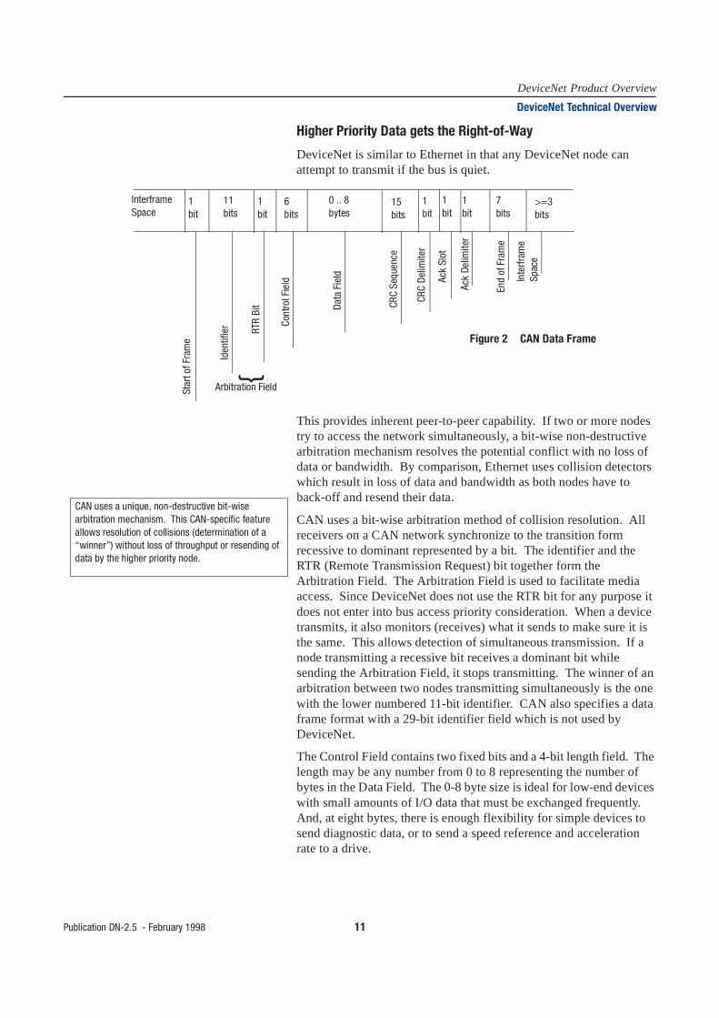
Higher Priority Data gets the Right-of-Way
DeviceNet is similar to Ethernet in that any DeviceNet node can attempt to transmit if the bus is quiet.
This provides inherent peer-to-peer capability. If two or more nodes try to access the network simultaneously, a bit-wise non-destructive arbitration mechanism resolves the potential conflict with no loss of data or bandwidth. By comparison, Ethernet uses collision detectors which result in loss of data and bandwidth as both nodes have to back-off and resend their data.
CAN uses a bit-wise arbitration method of collision resolution. All receivers on a CAN network synchronize to the transition form recessive to dominant represented by a bit. The identifier and the RTR (Remote Transmission Request) bit together form the Arbitration Field. The Arbitration Field is used to facilitate media access. Since DeviceNet does not use the RTR bit for any purpose it does not enter into bus access priority consideration. When a device transmits, it also monitors (receives) what it sends to make sure it is the same. This allows detection of simultaneous transmission. If a node transmitting a recessive bit receives a dominant bit while sending the Arbitration Field, it stops transmitting. The winner of an arbitration between two nodes transmitting simultaneously is the one with the lower numbered 11-bit identifier. CAN also specifies a data frame format with a 29-bit identifier field which is not used by DeviceNet.
The Control Field contains two fixed bits and a 4-bit length field. The length may be any number from 0 to 8 representing the number of bytes in the Data Field. The 0-8 byte size is ideal for low-end devices with small amounts of I/O data that must be exchanged frequently. And, at eight bytes, there is enough flexibility for simple devices to send diagnostic data, or to send a speed reference and acceleration rate to a drive.
InterframeSpace
1bit
1bit
1bit
1bit
1bit
11bits
6bits
0 .. 8bytes
15bits
>=3bits
7bits
Star
t of F
ram
e
Iden
tifie
r RTR
Bit
Cont
rol F
ield
Data
Fie
ld
CRC
Sequ
ence
CRC
Delim
iter
Ack
Slot
Ack
Delim
iter
End
of F
ram
e
Inte
rfram
eSp
ace
Figure 2 CAN Data Frame
}
Arbitration Field
CAN uses a unique, non-destructive bit-wise arbitration mechanism. This CAN-specific feature allows resolution of collisions (determination of a “winner”) without loss of throughput or resending of data by the higher priority node.

12 Publication DN-2.5 - February 1998
DeviceNet Product OverviewDeviceNet Technical Overview
The CRC field is a cyclic redundancy check word which is used by CAN controllers to detect frame errors. It is computed from the bits that come before it. A dominant bit in the ACK slot means at least one receiver besides the transmitter heard the transmission.
CAN uses several types of error detection and fault confinement methods including CRC and automatic retries. These methods, which are mostly transparent to the application, prevent a faulty node from disrupting the network.
CAN References 1. Anonymous, MC68HC05X4 HCMOS Microcomputer Unit,Motorolla LTD., 1992
2. Terry, K., Software Driver Routines for the Motorola MC68C05 CAN Module (AN464), Motorola LTD., 1993
3. Anonymous, 80c51 - Based 8-bit Microcontrollers, Data handbook IC20, Philips, 1995
4. Anonymous, 82527 Serial Communication Controller architectural Overview, Intel Corporation, February, 1995, Order Number: 272410-002
5. Anonymous, 8227 Serial Communications Controller, Controller Area Network Protocol, Intel Corporation, December, 1995 Order Number: 272250-006
6. Anonymous, 87C196CA/87C196CB Advanced 16-bit CHMOS Micorcontroller with Integrated CAN 2.0, Intel Corporation, October, 1993, Order Number; 272405-002
7. BOSCH CAN Specification—Version 2.0, Part A. 1991, Robert Bosch GmbH
8. ISO 11898: 1993 - Road vehicles - Interchange of digital information - Controller area network (CAN) for high-speed communication

Publication DN-2.5 - February 1998 13
DeviceNet Product OverviewDeviceNet Technical Overview
Communication Protocol and Application Applications using DeviceNet combine standard or application specific objects together into Device Profiles. The Device Profile fully defines the device as viewed from the network. A library of objects and Device Profiles is contained in the DeviceNet Specifications. ODVA coordinates the work of industry experts in the development of both new Object and Device Profile Specifications. This is done through Special Interest Groups (SIGs).
DeviceNet supports strobed, polled, cyclic, change-of-state, and application-triggered data movement. The user can choose master/slave, multi-master and peer-to-peer, or a combination configuration depending on device capability and application requirements. The choice of data movement can significantly speed up system response time. One popular application for DeviceNet is to use a standard, pre-defined set of connections which allow devices to operate in a Master/Slave Connection Set.
Connections
The DeviceNet Communication Protocol is based on the idea of connections. You must establish a connection with a device in order to exchange information with that device.
To establish a connection, each DeviceNet product will implement either an Unconnected Message Manager (UCMM) or an Unconnected Port. Both perform their function by reserving some of the available CAN identifiers.
When either the UCMM or the Unconnected Port is used to establish an Explicit Messaging Connection, that connection is then used to move information from one node to the other, or to establish additional I/O connections. Once connections have been established, I/O data may be moved among devices on the network. At this point, all the protocol of the DeviceNet I/O message is contained within the 11-bit CAN identifier. Everything else is data.
The 11-bit CAN identifier is used to define the connection ID. DeviceNet divides the 11-bit CAN identifier into four groups. The first three defined groups contain two fields—one 6-bit field for MAC ID and the other for Message ID. The combined fields define the connection ID.

14 Publication DN-2.5 - February 1998
DeviceNet Product OverviewDeviceNet Technical Overview
Devices may be clients or servers or both. Clients and servers may be producers, consumers or both. In a typical client device, its connection would produce requests and consume responses. In a typical server device, its connections would consume requests and produce responses. DeviceNet provides for several variations on this model. Some connections in either a client or a server may only consume messages. These connections would be the destination for cyclic or change-of-state messages. Similarly, some connections in either a client or server may only produce messages. These connections would be the source for cyclic or change-of-State messages. The use of cyclic or change-of-State connections can substantially reduce bandwidth requirements.
By design, nodes in a DeviceNet system are responsible for managing their own identifiers. These identifiers are distributed throughout the entire range. All nodes have a full range of message priorities available to them regardless of their MAC ID. Through the duplicate MAC ID algorithm, the uniqueness of CAN identifiers is guaranteed without the need for a central tool or record for each network.
A related issue is detection of duplicate nodes. Because DeviceNet uses a device address inside the CAN Identifiers Field, it presents a mechanism for detecting duplicate addressed devices. Preventing duplicate addresses is better than trying to locate them after they occur—something not taken into account in other CAN-based networks.
Another key benefit to nodes managing their identifiers is that a user can add and delete nodes and add additional peer-to-peer messages among existing nodes at any time without having knowledge of the existing set-up. No centralized record must be located or reconstructed. Since nodes know which IDs are already in use, a tool simply has to request an I/O connection be added between the two devices, specifying priority level, the data path, and the production trigger.

Publication DN-2.5 - February 1998 15
DeviceNet Product OverviewDeviceNet Technical Overview
The Object Model The Object Model provides a template for organizing and implementing the Attributes, Services and Behaviors of the components of a DeviceNet product.
The model provides an addressing scheme for each Attribute consisting of four numbers. They are the Node Address, the Object Class Identifier, the Instance Number, and the Attribute Number. This four-level address is used in conjunction with an Explicit Messaging Connection to move data from one place to another on a DeviceNet network. The ranges of the four addressing components are shown in the following table:
Typical Object Classes for DeviceNet The following are the typical object classes found in a DeviceNet product.
Identity Object
A DeviceNet product will typically have a single instance of the Identity Object. This instance will have as attributes a Vendor ID, a Device Type, a Product code, a revision, a status, a serial number, a product name, and a state. The required services would be Get_Attribute_Single and a Reset.
ApplicationObject(s)
ParameterObject
MessageRouter
IdentityObject
AssemblyObject
IO ExplicitMsg
DeviceNetObject
Connection
ApplicationObject
CommunicationsObjects
Shaded objectclasses are required
DeviceNet Network
Volume II
Volume I
Address Lowest Highest
Node 0 63
Class 1 65535
Address 0 65535
Attribute 1 255

16 Publication DN-2.5 - February 1998
DeviceNet Product OverviewDeviceNet Technical Overview
Message Router Object
A DeviceNet product will typically have a single instance of the Message Router Object. The Message Router Object is the component of a product that passes Explicit Messages to the other Objects. It generally does not have any external visibility over the DeviceNet network.
DeviceNet Object
A DeviceNet product will typically have a single instance of the DeviceNet Object. This instance would have as attributes: Node, Address, or MAC ID, baud rate, Bus-Off action, Bus-Off counter, the allocation choice, and the master’s MAC ID. The only required service is Get_Attribute_Single.
Assembly Object(s)
A DeviceNet product will typically have one or more optional Assembly Objects. The primary purpose of these objects is to group different Attributes (data) from different application objects into a single Attribute which can be moved with a single message.
Connection Objects
A DeviceNet product will typically have at least two connection objects. Each connection object represents one end point of a virtual connection between two nodes on a DeviceNet network. These two types of connections are called Explicit Messaging and I/O Messaging. Explicit Messages contain Attribute addressing, Attribute values and a Service Code describing the desired action. I/O messages contain nothing but data. In an I/O message, all the information about what to do with the data is contained in the Connection Object associated with that I/O message.
Parameter Object
The optional Parameter object would be used in devices with configurable parameters. One instance would be presented for each configurable parameter. The Parameter object provides a standard way for a configuration tool to access all parameters. Configuration options which are attributes of the Parameter object could include values, ranges, text strings, and limits.
Application Objects
Usually at least one application object besides those from the Assembly or Parameter Class will be present in a device. There are a number of standard objects in the DeviceNet Object Library.
Messaging The DeviceNet application layer defines how identifiers are assigned (thus controlling priorities), and how the CAN data field is used to specify services, move data, and determine its meaning.

Publication DN-2.5 - February 1998 17
DeviceNet Product OverviewDeviceNet Technical Overview
The way information flows on a communication network is critical. Older communication technology consisted of messages that wereconstructed with a specific source and destination. Instead of a traditional source-destination approach, DeviceNet uses a more efficient Product-Consumer Model which requires packets to have identifier fields for data. The identifier provides the means for multiple priority levels (used in arbitration), more efficient transfer of I/O data, and multiple consumers.
The device with data produces the data on the network with proper identifier. All devices who needed data listen for messages. When devices recognize the appropriate identifier, they consume the data. With the Producer-Consumer Model, the message is no longer specific to a particular source or destination. A single message from one controller can be used by multiple motor starters using less bandwidth.
DeviceNet defines two different types of messaging.
• I/O Messaging• Explicit Messaging
I/O Messages are for time-critical, control-oriented data. They provide a dedicated, special-purpose communication path between a producing application and one or more consuming applications. They are exchanged across single or multi-cast connectors and typically use high priority identifiers. I/O messages contain a protocol in the 8-byte data field. The only exception is for fragmented I/O messages where one byte is used for fragmentation protocol. The meaning of the message is implied by the connection ID (CAN identifier). Before messages are sent using these IDs, both the device sending and receiving them must be configured. The configuration contains the source and destination object attribute addresses for the producer and consumer of the data.
Explicit Messages provide multi-purpose, point-to-point communication paths between two devices. They provide the typical request/response-oriented network communications used to perform node configuration and problem diagnosis. Explicit Messages typically use low priority identifiers and contain the specific meaning of the message right in the data field. This includes the service to be performed and the specific object attribute address.
Fragmentation services are provided for messages that are longer then 8 bytes. Each I/O Message fragment incurs only a single byte of protocol overhead. There is no limit on the number of fragments. Fragmentation is also defined for explicit messaging. This flexibility assures that as more sophisticated devices are introduced and more capabilities are designed into devices, they can be added to existing DeviceNet networks. With its object-oriented design and addressing scheme, DeviceNet is unlimited in its ability to expand without having to alter the basic protocol and connection model.

18 Publication DN-2.5 - February 1998
DeviceNet Product OverviewDeviceNet Technical Overview
On the other end of the spectrum, a simple slave device application with two message connections (one I/O and one explicit) can be handled in less than 4 K ROM and 175 bytes of RAM (Motorola 68HCo5X4, a CPU with a built-in CAN interface).
The general format for I/O and Explicit messages are shown here.
Predefined Master/Slave Connection Set While DeviceNet provides a powerful Application Layer Protocol that allows for dynamic configuring of connections between devices, it has been recognized that some devices will have neither the need nor the resources to use this powerful capability. For this reason, a set of connection identifiers know as the Predefined Master/Slave Connection Set has been specified to simplify the movement of I/O configuration-type data typically seen in a master/slave architecture.
Many sensors and actuators are designed to perform some predetermined function (sense pressure, start motor, etc.) and the type and amount of data the device will produce or consume is know at power-up. Typically these devices provide input data or require output data and configuration data. The Predefined Master/Slave Connection Set meets these needs by providing connection objects that are almost entirely configured at the time the device powers up. The only remaining step necessary to begin the flow of data is for a master device to claim ownership of this predefined connection set within its slave(s).
Application I/O DataCANHeader
CANTrailer
Data Field (0 .. 8 bytes)
Format for I/O Message
Protocol Fields &Service Specific Data
CANHeader
CANTrailer
Data Field (0 .. 8 bytes)
Format for Explicit Message

Publication DN-2.5 - February 1998 19
DeviceNet Product OverviewDeviceNet Technical Overview
Message Group 2 is used for the definition of these identifiers. One noticeable difference in Group 2 is that the MAC ID is not specified as Source MAC ID. This allows the use of the Destination ID. Thereare strict rules about the use of this kind of connection to prevent duplicate CAN identifiers on the bus. The use of Destination ID allows devices which are centralized and which must communicate with many nodes (a master) to borrow identifiers from those nodes. In addition, the MAC ID and Message ID fields are reversed. This allows the Group ID and MAC ID to fall within the most significant 8 bits of the CAN identifier. This is important because many low-cost, 8-bit CAN chips can hardware filter only the first 8 bits. The exclusive use of Destination MAC ID further allows devices to take advantage of hardware filtering. Another important benefit is that the establishment of connections from the Predefined Set is simplified considerably. Only a few messages are required to have I/O connections up and running. The Predefined Set contains one explicit messaging connection and allows several different I/O connections including:
• bit Strobed Command/Response• polled Command/Response• change-of-State• cyclic
Change-of-State and Cyclic Transmission
With change-of-state, a device produces its data only when it changes. To be sure the consuming device knows that the producer is still alive and active, DeviceNet provides an adjustable, background heartbeat rate. Devices send data whenever they change or the heartbeat timer expires. This keeps the connection alive and lets the consumer know the data source has not faulted. The minimum time on the heartbeat prevents inherently noisy nodes from dominating the network. By having the device generate the heartbeat, the controller is not burdened with having to send a nuisance request periodically just to make sure it is alive. This becomes even more efficient in the multicast case.
The cyclic option can reduce unnecessary traffic and packet processing. Instead of a temperature or analog input block being scanned dozens of time each second, it can be set up to report its data on a regular basis consistent with the rate of change it can detect. A temperature sensor on a slow PID loop with a 500 ms update time could have its cyclic rate set to 500 ms. Not only would this preserve bandwidth for more rapidly changing critical I/O data, it would also be more accurate as well. For example, it might be scanned once every 30 ms as part of a large scan list with many bytes of data per node on a heavily loaded master. This means that data used in a PID calculation might have been sampled anywhere from 470 to 530 ms. With cyclic production you know that the data samples will be at precisely 500 ms.

20 Publication DN-2.5 - February 1998
DeviceNet Product OverviewDeviceNet Technical Overview
By default, both change-of-state and cyclic are acknowledged exchanges (ACKs) so that the producer knows its intended consumer(s) received the data. For applications where change-of-state or cyclic rates are extremely fast, it make no sense to clutter up the network with ACK packets. Unnecessary ACKs can be suppressed with the Acknowledge Handler Object.
Now, even simple slave nodes can be set up to report at the most appropriate interval, whether that be cyclic or change-of-state. With the ACK Handler Object it is possible to have multiple consumers of the slaves’ data, not just the master. This multicast is especially useful for operator interface (OI) devices which can just listen for the data they needs, whether it is for display, alarm monitoring or data logging.
For alarm monitoring, it is important that a change-of-state not be missed, so the OI device would be included in the device’s ACK list, assuring a retry (or several retries) if for some reason the OI missed the message. On the other hand, if it was primarily a data collection device logging values every 5 seconds (and the node is producing values every 300 ms for control purposes), you would not have the logger set to ACK. If the logger misses a value, it can grab the next one 300 ms later.
Cyclic and change-of-state from the master are defined and selectable on a per node basis.
Device Profiles The DeviceNet specification goes beyond a physical connection protocol specification. It promotes interoperability by defining standard device models. All devices of the same model must support common identity and communication status data. Device-specific data is contained in device profiles that are defined for various device types. Simple devices form multiple vendors that comply with their device type profile will be logically interchangeable.
A device profile will contain the following sections:
• Definition of the device’s object model - This often contains a drawing like the one shown on page 15. Usually there are tables which list all of the object classes present in the device, the number of instances in each class, how each object effects behavior, and the public interfaces to each object.
• Definition of the device’s I/O data format - This usually includes definition of Assembly Object definition which contains the address (class, instance, and attribute) of the desired data components.
• Definition of the device’s configurable parameter and public interfaces to those parameters. This information is contained in an Electronic Data Sheet (EDS) which is included with the device’s user documentation.

Publication DN-2.5 - February 1998 21
DeviceNet Product OverviewDeviceNet Technical Overview
The DeviceNet specification defines an Electronic Data Sheet which is a simple file format that allows product-specific information to be made available by vendors for all other vendors. This makes possible user-friendly configuration tools that can be easily updated without having to constantly revise the configuration software tool.
In order not to restrict enhancements, means are also provided for addition of vendor specific, value-add options. The DeviceNet specification has public classes, services and attributes which are defined in the DeviceNet specification and vendor-specific classes, services and attributes which can be added by individual vendors. This allows vendors to provide additional functions to their customers that are not covered in the specification. As vendor-specific items become more popular or commonplace, the mechanism to transition them to public items provided.
22 Publication DN-2.5 - February 1998
DeviceNet Product OverviewGlobal Technical Services DeviceNet Customer Training
Designing and Configuring aDeviceNet Network using
DeviceNetManager ™ Software(CCP163)
This course provides the skills necessary to design and configure a DeviceNet network. The course begins with an introduction to specifications for node quantities, device and network media selection, cable length calculation, and power requirements and placement. The configuring section of the course covers the data organization of the DeviceNet scanner data tables and devices, and data exchange flow in a network. Participants will then have an opportunity to use DeviceNetManger software to configure, monitor, and validate a DeviceNet network. A workstation with DeviceNet devices is used to simulate a DeviceNet network.
Upon completion of this course, you will be able to design and configure a DeviceNet network by performing these actions:
• select the appropriate network devices• determine the appropriate taps, connectors, and cables• determine the requirements and placement of power supplies• plan a physical layout• prepare the documentation for configuring a DeviceNet network• map a 1747-SDN scanner’s data tables• use DeviceNetManager software to configure a DeviceNet
network• select the different options of data mapping
DeviceNet Training Courses
Please contact your nearest Rockwell Automation sales office for information on the following:
• locations• schedules• detailed course descriptions• pricing

Publication DN-2.5 - February 1998 23
DeviceNet Product OverviewDeviceNet Physical Media
Related Publications
Understanding the DeviceNetCable System
The cable system uses a trunk/drop line topology and its components begin at the connection point of your device to the DeviceNet network. Devices (or nodes) are generally connected to the drop line or multiport taps. These in turn are connected to the trunk line via a sealed-style, open-style, or multiport taps.
How to Refer to the Cables You can connect components using three cable types:
For information on See pageThick Cable 25
Thin Cable 25
Preterminated Thin Cable Cordsets 25
Preterminated Thick Cable Cordsets 26
ArmorBlock Cordsets 26
KwikLink™ Flat Media System 27
T-Port Tap 27
DevicePort Tap 28
DeviceBox Tap 28
Sealed PowerTap Tap 28
Open-style PowerTap Tap 28
Sealed-Style Terminators 28
Open-Style Terminators 29
5-Point Open-Style Connector Tap 29
Open-Style Linear Plugs 29
Accessories 29
Stainless Steel Products 30
Allen-Bradley DeviceNet physical media is the most extensive offering available on the market today. There is a wide selection of open-style and sealed-style taps. Drop lines have a CPE jacket for corrosive environments. Stainless steel options are also available for a wide range of media products.
Title Publication NumberDeviceNet Cable System Planning and Installation Manual DN-6.7.2
DeviceNet Media System Component List DN-2.1
TR TR
Node NodeNode
NodeNode
Node
NodeNode
Node
Node
Trunk Line
Drop Line Drop LineMultiport Tap
Multiport Tap
Trunk line can be 500m (1641 ft) and drop line lengths can be up to 6m (20 ft). This assumes a baud rate of 125K.
This cable Is used
Thick Generally used as the trunk line for a DeviceNet network with an outsidediameter of 12.2mm (0.48in). You can also use this cable for drop lines.�
Thin Generally used as the drop line connecting devices to the trunk line with an outside diameter of 6.9mm (0.27in). This cable has a smaller diameter and is more flexible. You can also use this cable for trunk line.�
Flat (KwikLink)
Used exclusively as the trunkline for a DeviceNet network. Flat cable allows for clamp-on Insulation Displacement Connections (IDC).
� See the DeviceNet Cable System Planning and Installation Manual (DN-6.7.2) for restrictions.
24 Publication DN-2.5 - February 1998
DeviceNet Product OverviewDeviceNet Physical Media
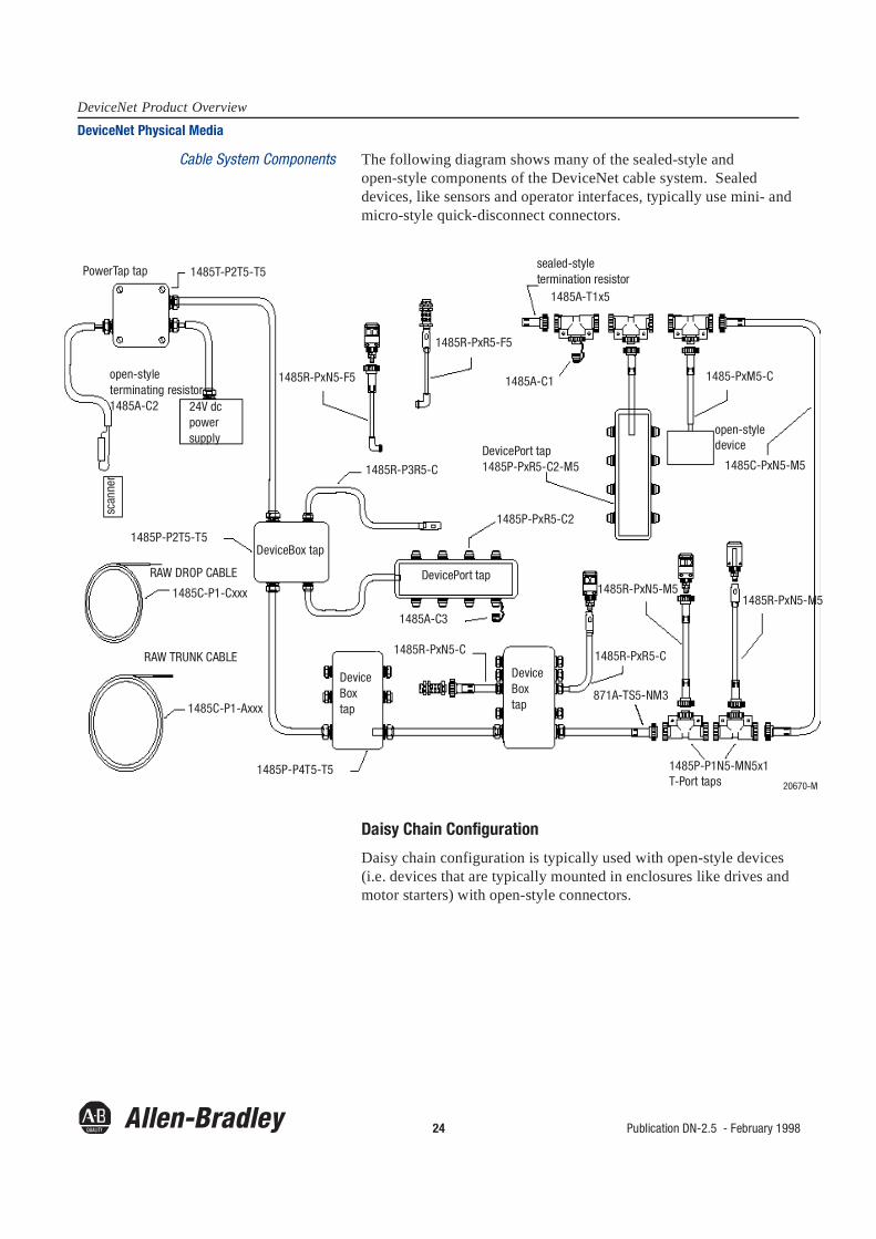
Cable System Components The following diagram shows many of the sealed-style and open-style components of the DeviceNet cable system. Sealed devices, like sensors and operator interfaces, typically use mini- and micro-style quick-disconnect connectors.
Daisy Chain Configuration
Daisy chain configuration is typically used with open-style devices (i.e. devices that are typically mounted in enclosures like drives and motor starters) with open-style connectors.
PowerTap tap 1485T-P2T5-T5
open-style terminating resistor 1485A-C2 24V dc
power supply
scan
ner
1485R-PxN5-F5
1485R-PxR5-F5
sealed-styletermination resistor
1485A-T1x5
1485A-C1 1485-PxM5-C
1485C-PxN5-M5
open-style deviceDevicePort tap
1485P-PxR5-C2-M5
1485P-P2T5-T5DeviceBox tap
1485R-P3R5-C
RAW DROP CABLE
1485C-P1-Cxxx
RAW TRUNK CABLE
1485C-P1-Axxx
DevicePort tap
1485P-PxR5-C2
DeviceBox tap
1485P-P4T5-T5
1485A-C3
1485R-PxN5-C
DeviceBox tap
1485R-PxR5-C
871A-TS5-NM3
1485R-PxN5-M51485R-PxN5-M5
1485P-P1N5-MN5x1T-Port taps 20670-M
Publication DN-2.5 - February 1998 25
DeviceNet Product OverviewDeviceNet Physical Media
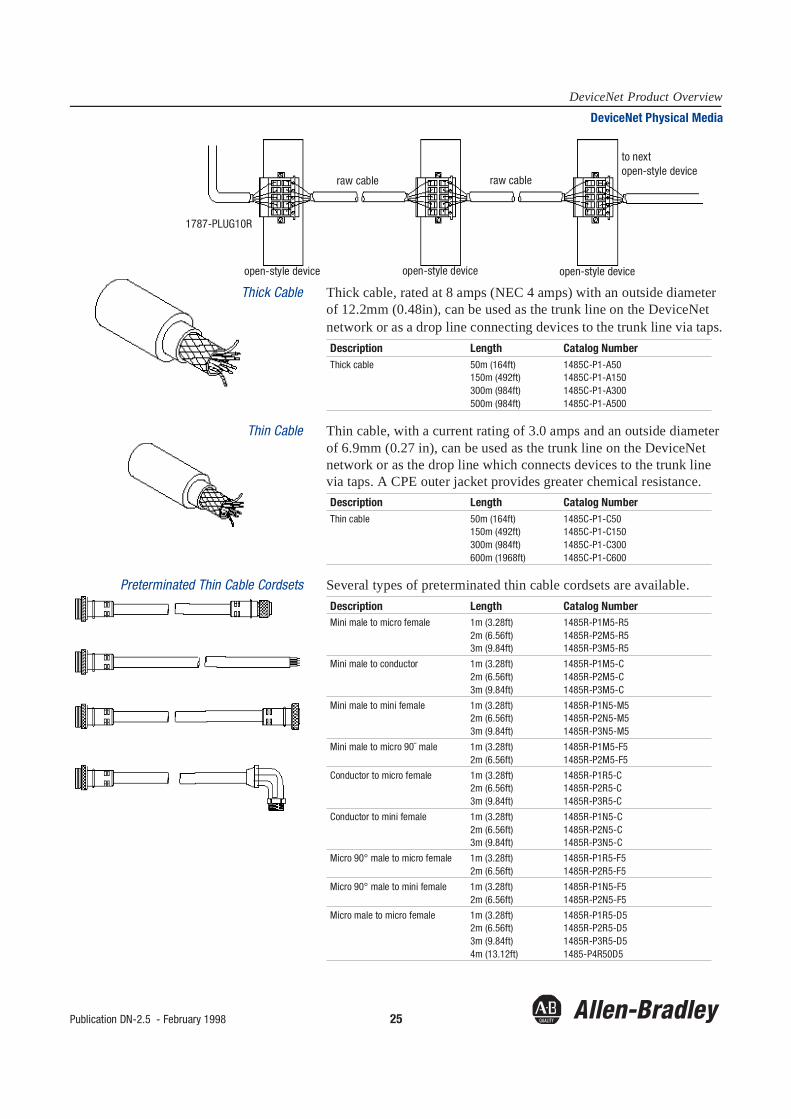
Thick Cable Thick cable, rated at 8 amps (NEC 4 amps) with an outside diameter of 12.2mm (0.48in), can be used as the trunk line on the DeviceNet network or as a drop line connecting devices to the trunk line via taps.
Thin Cable Thin cable, with a current rating of 3.0 amps and an outside diameter of 6.9mm (0.27 in), can be used as the trunk line on the DeviceNet network or as the drop line which connects devices to the trunk line via taps. A CPE outer jacket provides greater chemical resistance.
Preterminated Thin Cable Cordsets Several types of preterminated thin cable cordsets are available.
1787-PLUG10R
open-style device open-style device open-style device
raw cable raw cable
to nextopen-style device
Description Length Catalog NumberThick cable 50m (164ft)
150m (492ft)300m (984ft)500m (984ft)
1485C-P1-A501485C-P1-A1501485C-P1-A3001485C-P1-A500
Description Length Catalog NumberThin cable 50m (164ft)
150m (492ft)300m (984ft)600m (1968ft)
1485C-P1-C501485C-P1-C1501485C-P1-C3001485C-P1-C600
Description Length Catalog NumberMini male to micro female 1m (3.28ft)
2m (6.56ft)3m (9.84ft)
1485R-P1M5-R51485R-P2M5-R51485R-P3M5-R5
Mini male to conductor 1m (3.28ft)2m (6.56ft)3m (9.84ft)
1485R-P1M5-C1485R-P2M5-C1485R-P3M5-C
Mini male to mini female 1m (3.28ft)2m (6.56ft)3m (9.84ft)
1485R-P1N5-M51485R-P2N5-M51485R-P3N5-M5
Mini male to micro 90¯ male 1m (3.28ft)2m (6.56ft)
1485R-P1M5-F51485R-P2M5-F5
Conductor to micro female 1m (3.28ft)2m (6.56ft)3m (9.84ft)
1485R-P1R5-C1485R-P2R5-C1485R-P3R5-C
Conductor to mini female 1m (3.28ft)2m (6.56ft)3m (9.84ft)
1485R-P1N5-C1485R-P2N5-C1485R-P3N5-C
Micro 90° male to micro female 1m (3.28ft)2m (6.56ft)
1485R-P1R5-F51485R-P2R5-F5
Micro 90° male to mini female 1m (3.28ft)2m (6.56ft)
1485R-P1N5-F51485R-P2N5-F5
Micro male to micro female 1m (3.28ft)2m (6.56ft)3m (9.84ft)4m (13.12ft)
1485R-P1R5-D51485R-P2R5-D51485R-P3R5-D51485-P4R50D5

26 Publication DN-2.5 - February 1998
DeviceNet Product OverviewDeviceNet Physical Media
Preterminated Thick Cable Cordsets Preterminated thick cable cordsets are available.
ArmorBlock Cordsets Preterminated cables for use with ArmorBlock I/O blocks (1792 series) are available.
These cordsets provide connection to both I/O and power, and areavailable in a variety of lengths and connection configurations.
Allen-Bradley also offers custom cables and cordsets. However, lead times on custom products are longer than that of standard products. Please contact your local Allen-Bradley sales representative or distributor for more information.
Description Length Catalog NumberMini male to mini female 1m (3.28ft)
2m (6.56ft)3m (9.84ft)5m (16.41ft)10m (32.81ft)
1485C-P1N5-M51485C-P2N5-M51485C-P3N5-M51485C-P5N5-M51485C-P10N5-M5
Description Length Catalog NumberMini female 3 pin to conductor 5m (16.41ft)
4m (13.12ft)871A-CS3-DN5 (3 Amp)871A-CS3-DN4 (8 Amp)
Micro male 4 pin to conductor 1m (3.28ft) 871A-CS4-DM1
2m (6.56ft) 871A-CS4-DM2
3m (9.84ft) 871A-CS4-DM3
Micro male 4 pin to mini female 4 pin
1m (3.28ft) 871A-CS4-DM1N
2m (6.56ft) 871A-CS4-DM2N
3m (9.84ft) 871A-CS4-DM3N
Micro male 4 pin to micro female 4 pin
1m (3.28ft) 871A-CS4-DM1D
2m (6.56ft) 871A-CS4-DM2D
3m (9.84ft) 871A-CS4-DM3D
Micro male 4 pin to micro female 5 pin
1m (3.28ft) 871A-CS4-DM1D5
2m (6.56ft) 871A-CS4-DM2D5
3m (9.84ft) 871A-CS4-DM3D5
Micro male 4 pin splitter to conductor (for 16 point blocks)
5m (16.41ft) 871A-CS4-DM5X
Micro 4-pin splitter tee (for 16 point blocks)
1485P-P1R4-DR4
Micro male 4 pin right angle terminal chamber
18 AWG, 1 key 871A-TR4-DM
Micro male 4 pin straight terminal chamber
22 AWG, 1 key 871A-TS4-DM
18AWG, 1 key 871A-TS4-DM1

Publication DN-2.5 - February 1998 27
DeviceNet Product OverviewDeviceNet Physical Media
KwikLink™ Flat Media System The KwikLink flat media system is UL listed for 600V environments, 8 amps max current at 24V dc, and for outdoor use. It supports 64 nodes with trunk length restrictions. This new physical media system will reduce the cost of wiring a DeviceNet installation by 50%.
Note: KwikLink flat media products will be available in Summer 1998.
T-Port Tap The T-Port tap connects to a single device or drop line to the trunk. The mini quick-disconnect style T-Port taps have right or left keyway for positioning purposes. They also come with either mini or micro connectors The micro style T-Port tap should be used in thin trunk systems.
Description Catalog NumberFlat cable spool (450 meters) 1485C-P1-E450
Flat cable spool (200 meters) 1485C-P1-E200
Flat cable spool (75 meters) 1485C-P1-E75
Flat micro connector (NEMA 1) 1485P-P1H4-R5
Flat micro connector (NEMA 6P, 13) 1485P-P1E4-R5
Flat open style connector 1485P-P1H4-T4
Flat termination (NEMA 6P, 13) 1485A-T1E4
Flat termination (NEMA 1) 1485A-T1H4
* Denotes cable length in meters
Open connector Modules1485P1H4-R5
Micro Connector Module
PowerSupply
OpenStyle
Terminator
PLCEnclosure
Flat Trunk Cable1485C-P-E* Micro Connector Modules
NEMA1:1485P-P1H4-R5NEMA6P:1485P-P1E4-R5
TerminatorNEMA1:1485A-T1H4NEMA6P:1485P-1485A-T1E4
40898
Description Catalog NumberMini T-Port tap with right keyway 1485P-P1N5-MN5R1
Mini T-Port tap with left keyway 1485P-P1N5-MN5L1
Micro T-Port tap 1485P-P1R5-DR5

28 Publication DN-2.5 - February 1998
DeviceNet Product OverviewDeviceNet Physical Media
DevicePort Tap DevicePort taps are sealed, passive multiport taps that connect to the trunk line via drop lines with quick-disconnect connectors or conductor/pigtail. A DevicePort tap connects clusters of DeviceNet-compatible devices to the network.
DeviceBox Tap DeviceBox multiport passive taps are a direct connection onto the trunk line, providing terminal strip connections for up to 8 nodes using thin cable drop lines. They have a removable gasket cover and cable glands to provide a tight, sealed box that can be mounted on a machine or on a plant floor.
Sealed PowerTap Tap The sealed PowerTap™ tap provides 7.5 amps overcurrent protection to the thick cable. Multiple PowerTap taps may also be used to connect multiple power supplies to the trunk line.
Open-style PowerTap Tap The open-style Power Tap allows for two nodes to attach at the power tap. Additionally, the tap can be mounted in a NEMA enclosure DIM 72mm. x 87.5mm. PCB, as a replacement PCB in the 1485T-P2T5-T5 series B, or with a DIN rail mounting kit.
Sealed-Style Terminators Male and female terminators electrically stabilize DeviceNet communication using terminating resistors. All contacts are gold plated for corrosion resistance. Two pins on both terminators are connected with 121Ω 1% 1/4 watt metal film resistors.
Sealed-style terminators are suitable for use with T-Port taps.
Description Catalog Number4-port DevicePort tap with 2m drop line 1485P-P4R5-C2
4-port DevicePort tap with 2m mini male connector 1485P-P4R5-C2-M5
8-port DevicePort tap with 2m drop line 1485P-P8R5-C2
8-port DevicePort tap with 2m mini male connector 1485P-P8R5-C2-M5
Description Catalog Number2-port DeviceBox tap 1485P-P2T5-T5
4-port DeviceBox tap 1485P-P4T5-T5
8-port DeviceBox tap 1485P-P8T5-T5
DeviceBox accessory kit 1485-AccKit
Description Catalog NumberPowerTap tap 1485T-P2T5-T5
Description Catalog NumberOpen-style Power Tap 1485T-P2T5-T5N
Description Catalog NumberTerminator mini male 1485A-T1M5
Terminator mini female 1485A-T1N5
Publication DN-2.5 - February 1998 29
DeviceNet Product OverviewDeviceNet Physical Media
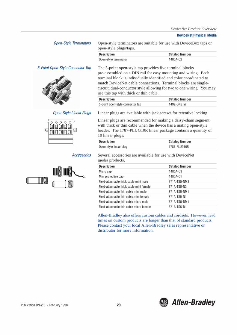
Open-Style Terminators Open-style terminators are suitable for use with DeviceBox taps or open-style plugs/taps.
5-Point Open-Style Connector Tap The 5-point open-style tap provides five terminal blocks pre-assembled on a DIN rail for easy mounting and wiring. Each terminal block is individually identified and color coordinated to match DeviceNet cable connections. Terminal blocks are single-circuit, dual-conductor style allowing for two to one wiring. You may use this tap with thick or thin cable.
Open-Style Linear Plugs Linear plugs are available with jack screws for retentive locking.
Linear plugs are recommended for making a daisy-chain segment with thick or thin cable when the device has a mating open-style header. The 1787-PLUG10R linear package contains a quantity of 10 linear plugs.
Accessories Several accessories are available for use with DeviceNet media products.
Allen-Bradley also offers custom cables and cordsets. However, lead times on custom products are longer than that of standard products. Please contact your local Allen-Bradley sales representative or distributor for more information.
Description Catalog NumberOpen-style terminator 1485A-C2
Description Catalog Number5-point open-style connector tap 1492-DN3TW
Description Catalog Number
Open-style linear plug 1787-PLUG10R
Description Catalog NumberMicro cap 1485A-C3
Mini protective cap 1485A-C1
Field-attachable thick cable mini male 871A-TS5-NM3
Field-attachable thick cable mini female 871A-TS5-N3
Field-attachable thin cable mini male 871A-TS5-NM1
Field-attachable thin cable mini female 871A-TS5-N1
Field-attachable thin cable micro male 871A-TS5-DM1
Field-attachable thin cable micro female 871A-TS5-D1

30 Publication DN-2.5 - February 1998
DeviceNet Product OverviewDeviceNet Physical Media
Stainless Steel Products DeviceNet physical media products are available with stainless steel couplings as a build-to-order product. These physical media products are available in stainless steel:
To order one of the above physical media products in stainless steel, add an S to the part number. For example, 1485R-P1N5-M5 becomes 1485RS-P1N5-M5. Custom cables of all types available. Contact your Allen-Bradley distributor for information.
Allen-Bradley offers the DeviceNet Assistant (DNA-900) an easy-to-use configuration software package used for determining the optimal placement and number of power supplies, required cabling, complete bill of materials, and maximum baud rate. DNA-900 is free and can be downloaded from www.ab.com.
• preterminated thin cable cordsets • DevicePort taps• preterminated thick cable cordsets • DeviceLink discrete input• mini T-Port taps

Publication DN-2.5 - February 1998 31
DeviceNet Product OverviewSeries 9000 Photoelectric Sensor
DeviceNet Features and Benefits• configurable via DeviceNet network and on the sensor itself for
light or dark operation, address, and communication rate• report of low-margin condition over the network• three connection options: mini quick disconnect, micro
disconnect, or attached 2m drop cable• supports COS and strobbing messages for higher performance
Product Features and Benefits• withstand temperatures up to 70° C (158° F), high-pressure
washdowns of up to 1,200 psi, and many harsh environments
• high-impact, chemically-resistant VALOX® housing• extended sensing ranges to minimize lens cleaning and
realignment• modular design simplifies troublshooting
Related Publications
Ordering Information
Available Mounting Kits
The PHOTOSWITCH® Series 9000 photoelectric sensor is designed to withstand harsh environments for use on the DeviceNet network.
Title Publication NumberSensor Catalog C112
Sensing Mode Connection Type Communication Protocol
Strobing Change-of-StateRetroflective 2m cable
micro QDmini QD
42GNU-900042GNU-900-QD42GNU-9000-QD1
42GNU-901042GNU-9010-QD42GNU-9010-QD1
Polarized Retroflective 2m cablemicro QDmini QD
42GNU-920042GNU-9200-QD42GNU-9200-QD1
42GNU-921042GNU-9210-QD42GNU-9210-QD1
Standard Diffuse 2m cablemicro QDmini QD
42GNP-900042GNP-9000-QD42GNP-9000-QD1
42GNP-901042GNP-9010-QD42GNP-9010-QD1
Transmitted Beam Receiver
2m cablemicro QDmini QD
42GNR-900042GNR-9000-QD42GNR-9000-QD1
42GNR-901042GNR-9010-QD42GNR-9010-QD1
IR Glass Fiber Optic 2m cablemicro QDmini QD
42GNF-900042GNF-9000-QD42GNF-9000-QD1
42GNF-901042GNF-9010-QD42GNF-9010-QD1
Visible Red Plastic Fiber Optic
2m cablemicro QDmini QD
42GNF-910042GNF-9100-QD42GNF-9100-QD1
42GNF-911042GNF-9110-QD42GNF-9110-QD1
ClearSight Clear Object Detector
2m cablemicro QDmini QD
42GNC-910042GNC-9100-QD42GNC-9100-QD1
42GNC-911042GNC-9110-QD42GNC-9110-QD1
This kit Provides Cat. No.• Swivel/Tilt Mounting Assembly Kit 360° rotation and 10° of tilt
adjustment60-2439
• Universal Mounting Assembly Kit 360° rotation, vertical and angular tilt adjustment, adjustable 10° in each direction
60-2421

32 Publication DN-2.5 - February 1998
DeviceNet Product OverviewDeviceNet RediSTATION Operator Interface
DeviceNet Features and Benefits• indication of network operation, panel operation, and burned out
or missing bulb• DIP-switch configuration of node address, communication rate,
flashing pilot light frequency
Product Features and Benefits• three 800T devices in a pre-assembled 3-hole station or “build
your own” custom stations• open style that accommodates most standard push buttons,
selector switches, or pilot lights that may be used in any position• flash-option on pilot-light output• NEMA 4X enclosure
Related Publication
Ordering Information
The RediSTATION™ operator interface is a push-button/pilot light/selector-switch unit with the added capability of DeviceNet communication.
Title Publication NumberRediSTATION User Manual 2705-804
Standard Configuration (stop push-button, start push-button, pilot light) with Mini DeviceNet Connector
2705-T3DN1A42A
Standard Configuration (stop push-button, start push-button, pilot light) with Open-Style DeviceNet Terminal Connector
2705-T3DN1B42A
3-hole Custom Configuration with Mini DeviceNet Connector 2705-T3DN1A42X
3-hole Custom Configuration with Open-Style DeviceNet Terminal Connector
2705-T3DN1B42X
DeviceNet Interface Communication Board (with I/O connector cables and DeviceNet PCB terminal block connector, (4) 24V dc input, (2) 24V dc output) with Open-Style DeviceNet Terminal Connector
2705-DN42
Publication DN-2.5 - February 1998 33
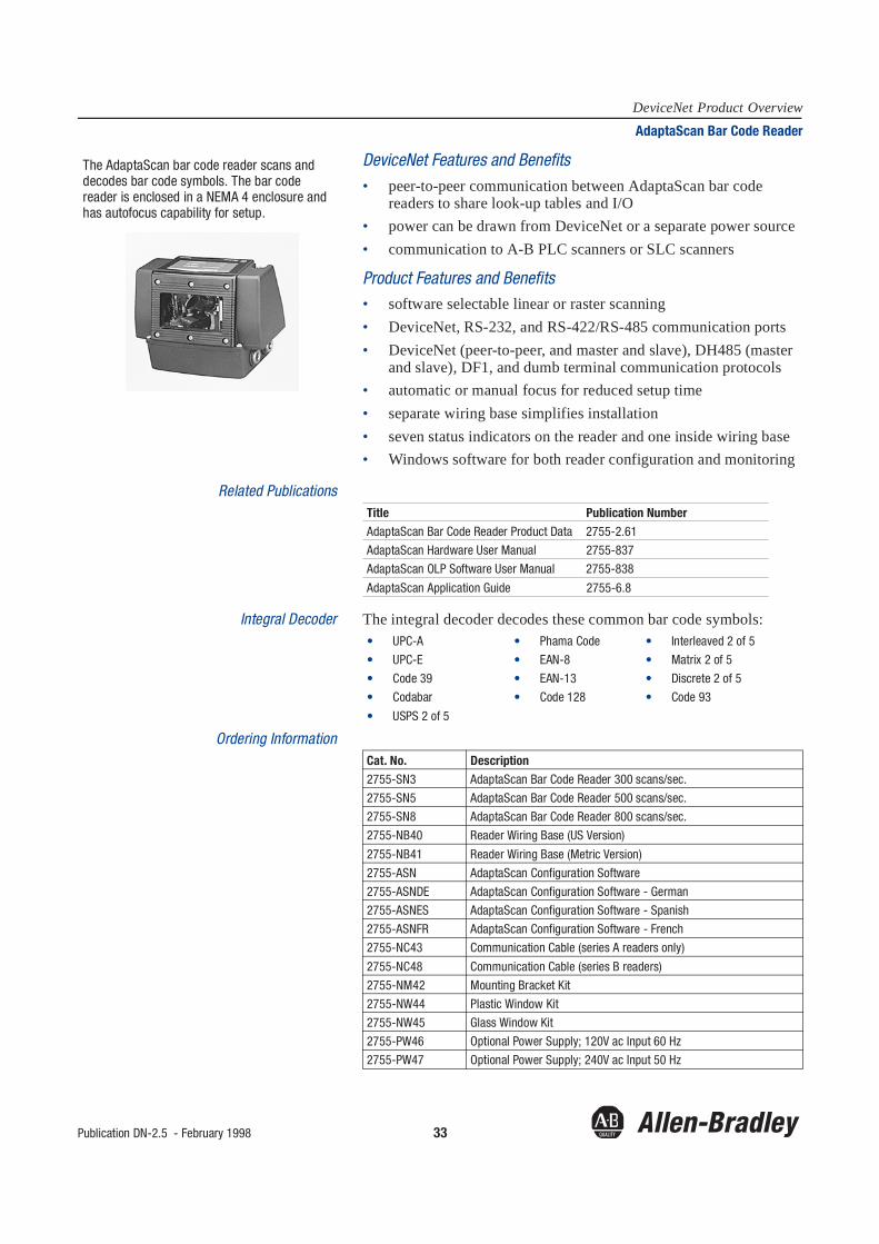
DeviceNet Product OverviewAdaptaScan Bar Code Reader
DeviceNet Features and Benefits• peer-to-peer communication between AdaptaScan bar code
readers to share look-up tables and I/O• power can be drawn from DeviceNet or a separate power source• communication to A-B PLC scanners or SLC scanners
Product Features and Benefits• software selectable linear or raster scanning• DeviceNet, RS-232, and RS-422/RS-485 communication ports• DeviceNet (peer-to-peer, and master and slave), DH485 (master
and slave), DF1, and dumb terminal communication protocols• automatic or manual focus for reduced setup time• separate wiring base simplifies installation• seven status indicators on the reader and one inside wiring base• Windows software for both reader configuration and monitoring
Related Publications
Integral Decoder The integral decoder decodes these common bar code symbols:
Ordering Information
The AdaptaScan bar code reader scans and decodes bar code symbols. The bar code reader is enclosed in a NEMA 4 enclosure and has autofocus capability for setup.
Title Publication NumberAdaptaScan Bar Code Reader Product Data 2755-2.61
AdaptaScan Hardware User Manual 2755-837
AdaptaScan OLP Software User Manual 2755-838
AdaptaScan Application Guide 2755-6.8
• UPC-A • Phama Code • Interleaved 2 of 5
• UPC-E • EAN-8 • Matrix 2 of 5
• Code 39 • EAN-13 • Discrete 2 of 5
• Codabar • Code 128 • Code 93
• USPS 2 of 5
Cat. No. Description2755-SN3 AdaptaScan Bar Code Reader 300 scans/sec.
2755-SN5 AdaptaScan Bar Code Reader 500 scans/sec.
2755-SN8 AdaptaScan Bar Code Reader 800 scans/sec.
2755-NB40 Reader Wiring Base (US Version)
2755-NB41 Reader Wiring Base (Metric Version)
2755-ASN AdaptaScan Configuration Software
2755-ASNDE AdaptaScan Configuration Software - German
2755-ASNES AdaptaScan Configuration Software - Spanish
2755-ASNFR AdaptaScan Configuration Software - French
2755-NC43 Communication Cable (series A readers only)
2755-NC48 Communication Cable (series B readers)
2755-NM42 Mounting Bracket Kit
2755-NW44 Plastic Window Kit
2755-NW45 Glass Window Kit
2755-PW46 Optional Power Supply; 120V ac Input 60 Hz
2755-PW47 Optional Power Supply; 240V ac Input 50 Hz
34 Publication DN-2.5 - February 1998
DeviceNet Product OverviewSmart Speed Controller (SSC) DeviceNet Communication Module - Bulletin 160
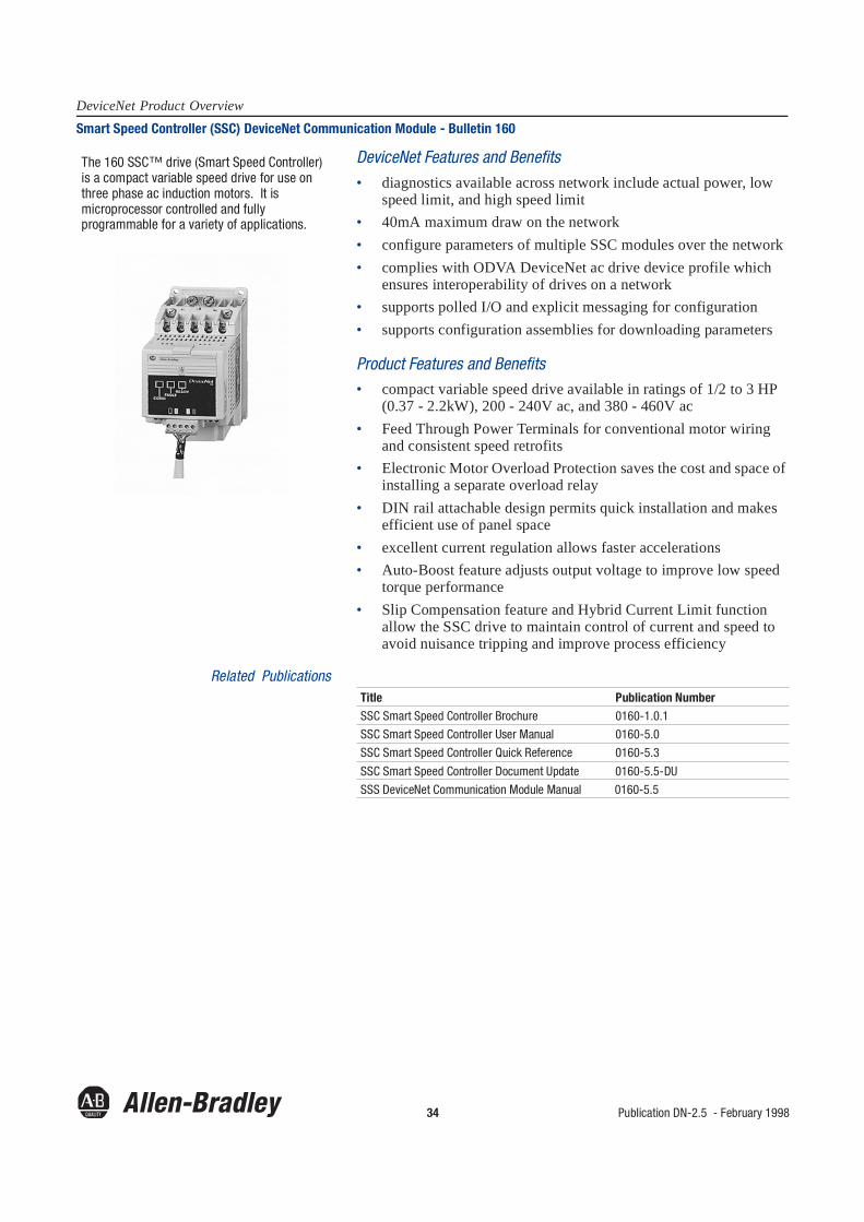
DeviceNet Features and Benefits• diagnostics available across network include actual power, low
speed limit, and high speed limit• 40mA maximum draw on the network• configure parameters of multiple SSC modules over the network• complies with ODVA DeviceNet ac drive device profile which
ensures interoperability of drives on a network• supports polled I/O and explicit messaging for configuration• supports configuration assemblies for downloading parameters
Product Features and Benefits• compact variable speed drive available in ratings of 1/2 to 3 HP
(0.37 - 2.2kW), 200 - 240V ac, and 380 - 460V ac• Feed Through Power Terminals for conventional motor wiring
and consistent speed retrofits• Electronic Motor Overload Protection saves the cost and space of
installing a separate overload relay• DIN rail attachable design permits quick installation and makes
efficient use of panel space• excellent current regulation allows faster accelerations• Auto-Boost feature adjusts output voltage to improve low speed
torque performance• Slip Compensation feature and Hybrid Current Limit function
allow the SSC drive to maintain control of current and speed to avoid nuisance tripping and improve process efficiency
Related Publications
The 160 SSC™ drive (Smart Speed Controller) is a compact variable speed drive for use on three phase ac induction motors. It is microprocessor controlled and fully programmable for a variety of applications.
Title Publication NumberSSC Smart Speed Controller Brochure 0160-1.0.1
SSC Smart Speed Controller User Manual 0160-5.0
SSC Smart Speed Controller Quick Reference 0160-5.3
SSC Smart Speed Controller Document Update 0160-5.5-DU
SSS DeviceNet Communication Module Manual 0160-5.5

Publication DN-2.5 - February 1998 35
DeviceNet Product OverviewDeviceNet Communication Module for Drives and Power Products (1203-K5, 1336-GM5, 1336F-GMS5)
DeviceNet Features and Benefits• supports all configurable parameters of the connected device• allows you to upload and edit a device's configuration (EDS)
online for use by DeviceNetManager software or other PC-based tools
• supports 4 - 20 words of I/O data through polling by a scanner• supports the capability of modifying device parameters from a
PLC program• supports change-of-state messaging for higher performance• explicit peer-to-peer messaging—allows multiple PC-based tools
to directly access data (up to 5 connections)• 1336F-GMS5 mountable onto the control board of any 1336
PLUS II drive—provides an easy connection to the DeviceNet network
Product Features and Benefits• status indicators provide a visual indication of the SCANport
interface and the DeviceNet interface• select your network address and data rate via DIP switches or
parameters• select your data size and fault/idle state via DIP switches
Related Publication
Ordering Information The 1203-GK5 NEMA Type 1 (DIN-rail mountable), and the 1336-GM5/1336F-GMS5 open-style (internally mountable) communication interface modules connect the following products to the DeviceNet network.
The DeviceNet communication module (1203-GK5) connects a 1305, 1336 PLUS II, 136 IMPACT™ AC drive, 1397 DC drive, 1394 Digital AC Multi-Axis Motion Control System, 1557 Medium Voltage Drive, SMP-3 overload relay, SMC Dialog Plus Controller or other SCAN port ™ product to a DeviceNet network.
The 1336-GM5 communication module (not pictured) is placed within the 1336 PLUS II or 1336 IMPACT drives, B frame and larger, providing an on-board connection to the DeviceNet network. In addition, the 1336F-GMS5 mounts onto the control board of any 1336 PLUS II drive providing an easy connection to the DeviceNet network.
Title Publication NumberDeviceNet Communications Module Manual 1203-5.3
Compatible Communication Module Product Description1203-GK5 only SMP-3 Smart Motor Protector
SMC Dialog Plus
1305 AC drive
1397 digital DC drive
1394 servo drive
1203-GK5 or 1336-GM5 1336 FORCE™ AC drive
1336 IMPACT™ AC drive
1203-GK5, 1336-GM5, or 1557-13GM5 1557 medium voltage drive
1203-GK5, 1336-GM5, or 1336-GMS5 1336 PLUS II AC drive

36 Publication DN-2.5 - February 1998
DeviceNet Product OverviewSmart Motor Protector (SMP-3) Solid-State Overload Relay
DeviceNet Features and Benefits• provides diagnostics across the network including motor current
draw, phase loss, ground fault, jam/stall fault, and % thermal capacity (0 to 100 where 100 represents an overload trip)
Product Features and Benefits• replaces three bimetallic overload relays and up to 10 heater
elements• quick identification of a tripped overload relay and the trip
caused by:- overload- ground fault- phase loss- jam/stall- illegal setting
• available for both IEC and NEMA starters• provides more accurate setting than traditional overload relays at
±2.5% setting accuracy
Related Publications
Ordering Information These SMP-3 solid-state overload relays are available:
• SMP-3 IEC version (overload and contactor)• NEMA non-reversing starter with SMP-3 solid-state
overload relay• NEMA full-voltage reversing starter with SMP-3 solid-state
overload relay
The Smart Motor Protector (SMP-3) solid-state overload relay provides solid-state motor overcurrent protection in addition to ground fault tripping, jam/stall protection, and protection against damage caused by phase loss conditions.
Bulletin 193 SMP-3 Overload Relay mounted on an IEC contactor.
Title Publication NumberIndustrial Control Catalog A112
SMP Overview Brochure 193-1.0
IEC Contactors and Overload Relays Brochure Bulletin 100
100-1.0.1
NEMA Starter Brochure Bulletin 509 509-1.3
SMP-3 Solid-State Overload Relay User Manual
193-5.0
SMP-3 Overload Relay as part of a NEMA starter.

Publication DN-2.5 - February 1998 37
DeviceNet Product OverviewSMC Dialog Plus Controller for the DeviceNet Network- Bulletin 150
DeviceNet Features and Benefits• program, monitor, and control the SMC Dialog Plus controller via
a DeviceNet network• diagnostics available across the network include phase reversal,
voltage unbalance, and excess starts per hour
Product Features and Benefits• multiple starting and stopping features that allow you to control
starting current, voltage, and torque• built-in electronic motor overload protection that reduces panel
space and labor requirements• extensive motor protection such as overload, underload, stall,
jam, line fault, and phase rebalance• meaningful motor diagnostics displayed locally in easy-to-read
text helps pinpoint system faults, minimizing downtime and simplifying troubleshooting
• programming is easily accomplished through the built-in keypad and LCD locally or from DeviceNetManager software remotely
Related Publications
Ordering Information The SMC Dialog Plus controller has the following options:
• soft stop• pump control• preset slow speed• SMB™ smart motor braking• Accu-Stop™• slow speed with braking
The SMC Dialog Plus™ controller for the DeviceNet Network controller provides soft starting and controlled stopping for three-phase squirrel cage motors rated 1 - 1000A, 200 - 600V ac, 50/60 Hz. It’s control voltage is 100 - 240V ac or 24V ac/dc.
The SMC Dialog Plus controller connects to a DeviceNet network through a 1203-GK5 interface module via the controller’s SCANport connection.
Title Publication NumberOverview and Selection Guide 150-1.1.1
Typical Specification 150-2.5
SMC Dialog Plus Product and Application Guide 150-5.2
38 Publication DN-2.5 - February 1998
DeviceNet Product Overview1305 AC Drive, 1336 PLUS AC Drive, 1336 IMPACT AC Drive, and 1397 DC Drive
1305 AC Drive Features and Benefits• microprocessor-controlled, adjustable frequency drive designed
for reliable control of 3-phase induction motors• NEMA 1 (IP30) enclosed drive• features hybrid current limit, inherent dynamic braking, and
built-in protective functions• 0.37 - 4.0kW (0.5 - 5 HP) 200 - 460V
1336 PLUS II AC Drive Features and Benefits• easy setup and operation, uncommon flexibility, and
outstanding performance• sensorless vector or volts-per-Hertz operation, parameter
selectable• uses the latest in IGBT (Insulated Gate Bipolar Transistor)
power technology• uses sophisticated control algorithms to provide smooth
performance, exceptional torque at any speed, and quiet efficient operation
• 0.37 - 448kW (0.5 - 600 HP) 200 - 600V
1336 IMPACT AC Drive Features and Benefits• precise speed and torque control that uses FORCE technology,
patented field-oriented control algorithms• sensorless motor temperature compensation, auto-tuning of speed
and torque loops, and switching from encoder-based field oriented control to encoderless control simply by choosing a parameter value
• 0.37 - 597kW (0.5 - 800 HP) 200 - 600V
1397 Digital DC Drive Features and Benefits• simple, compact, and cost effective for new and machine
upgrade applications• out-of-the-box startup for simple installations with available
options for added flexibility• 1.1 - 225kW (1.5 - 300 HP)
Related Publications
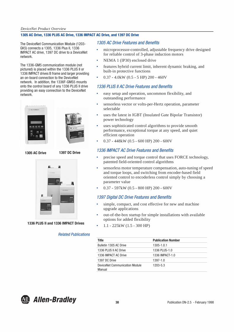
The DeviceNet Communication Module (1203-GK5) connects a 1305, 1336 Plus II, 1336 IMPACT AC drive, 1397 DC drive to a DeviceNet network.
The 1336-GM5 communication module (not pictured) is placed within the 1336 PLUS II or 1336 IMPACT drives B frame and larger providing an on-board connection to the DeviceNet network. In addition, the 1336F-GMS5 mounts onto the control board of any 1336 PLUS II drive providing an easy connection to the DeviceNet network.
1305 AC Drive 1397 DC Drive
1336 PLUS II and 1336 IMPACT Drives
Title Publication NumberBulletin 1305 AC Drive 1305-1.0.1
1336 PLUS II AC Drive 1336 PLUS-1.0
1336 IMPACT AC Drive 1336 IMPACT-1.0
1397 DC Drive 1397-1.0
DeviceNet Communication Module Manual
1203-5.3

Publication DN-2.5 - February 1998 39
DeviceNet Product Overview1557 Medium Voltage Drive
DeviceNet Features and Benefits• modify parameters to multiple drives across the network via a PC
or programmable controller• control operation of multiple drives across network via PC or
programable controller
Product Features and Benefits• wide product range 100 - 10,000 HP (2300 - 6900V)• no DV/DT stress to motor• no DI/DT stress to motor• virtually unlimited motor cable distance• inherent regenerative motor braking• low voltage test modes• 98.6% efficiency at full load and full speed
Related Publications
The 1557 Medium Voltage Drive uses CSI-PWM technology and direct vector control to provide near sinusoidal motor waveforms for use with new and retrofit standard ac motors.
The 1557 Medium Voltage Drive connects to a DeviceNet network through a 1203-GK5 or 1336-GM5 communication interface module. A 1557-13GM5 field-installable modification kit is also available.
Title Publication NumberThe Preferred Choice in M.V. Speed Control 1557-1.0
M.V. Speed Control Product Data 1557-1.1
M.V. Speed Control Specification Guide 1557-2.2

40 Publication DN-2.5 - February 1998
DeviceNet Product Overview1394 Digital AC Multi-Axis Motion Control System
DeviceNet Features and Benefits• configure, tune, and start up via PC or PLC processor• modify parameters adapt to application modes• read, load, and performance information for trending and
diagnostic use• read machine velocity or position
Product Features and Benefits• one to four axis-field configurable• state-of-the-art digital signal processing for superior performance• advanced auto-tuning and startup simplifies commissioning• Integrated Power Module (IPM) technology for smooth, efficient
power conversion
Related Publications
The 1394 is a full-featured, digital ac, closed-loop servo controller that integrates multi-axis motion control and servo drive func-tions into a single, compact system for high-per-formance position, velocity, and torque control of one to four servo motors.
The 1394 connects to the DeviceNet network through a 1203-GK5 interface module.
Title Publication Number1394 Overview Brochure 1394-1.0
1394 Product Data 1394-2.0
Publication DN-2.5 - February 1998 41
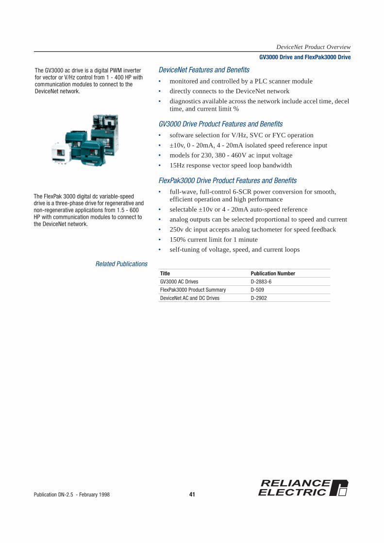
DeviceNet Product OverviewGV3000 Drive and FlexPak3000 Drive
DeviceNet Features and Benefits• monitored and controlled by a PLC scanner module• directly connects to the DeviceNet network• diagnostics available across the network include accel time, decel
time, and current limit %
GV3000 Drive Product Features and Benefits• software selection for V/Hz, SVC or FYC operation• ±10v, 0 - 20mA, 4 - 20mA isolated speed reference input• models for 230, 380 - 460V ac input voltage• 15Hz response vector speed loop bandwidth
FlexPak3000 Drive Product Features and Benefits• full-wave, full-control 6-SCR power conversion for smooth,
efficient operation and high performance• selectable ±10v or 4 - 20mA auto-speed reference• analog outputs can be selected proportional to speed and current• 250v dc input accepts analog tachometer for speed feedback• 150% current limit for 1 minute• self-tuning of voltage, speed, and current loops
Related Publications
The GV3000 ac drive is a digital PWM inverter for vector or V/Hz control from 1 - 400 HP with communication modules to connect to the DeviceNet network.
The FlexPak 3000 digital dc variable-speed drive is a three-phase drive for regenerative and non-regenerative applications from 1.5 - 600 HP with communication modules to connect to the DeviceNet network.
Title Publication NumberGV3000 AC Drives D-2883-6
FlexPak3000 Product Summary D-509
DeviceNet AC and DC Drives D-2902

42 Publication DN-2.5 - February 1998
DeviceNet Product OverviewEZLINK Monitor for Bearings and Speed Reducers
DeviceNet Features and Benefits• elimination of dedicated signal conditioners
and power supplies• less wiring than traditional methods• supports change-of-state messaging for higher performance• increased reliability for more uptime• low installation cost
Product Features and Benefits• online measurements of temperature, speed, pressure and
vibration• continuous on-line monitoring• dust-tight, waterproof enclosure
• ambients to 85o C• optional software available for trend analysis and network status
at a glance• serial communication up to 500KB• point and click configuration software provided with EZLINK for
address and limit setting• available for retrotit on existing applications
Related Publications
To order these publications, call the Greenville Fulfillment Center at 864-232-6681.
The EZLINK monitor provides low-cost online conditions monitoring for bearings and speed reducers.
The EZLINK bearing monitor works with the EZLINK software which was custom-written for the DeviceNet network.
Title Publication NumberEZLINK General Brochure DMR1572
EZLINK Technical Manual 499396
DODGE™ Bearing Catalog DMR-1203
DODGE Gearing Catalog DMR-1205
DODGE Bearing Monitor Brochure DMR-1269
DODGE TORQUE-ARM™ Harsh Duty Brochure
DMR-1467
Linking the Future Reprint (Retrotit flyer) DMR-1638

Publication DN-2.5 - February 1998 43
DeviceNet Product OverviewDeviceLink I/O
DeviceNet Features and Benefits• connects 2- or 3-wire 24V sensors with sourcing outputs; devices
with relay contacts and mechanical sensing devices• offered in a variety of cable lengths up to 3m (9ft)• contains user-configurable debounce filtering• offered in mini quick-disconnect, micro quick-disconnect, and
conductor styles• provides visual network diagnostics with a bicolor LED status
indicator• available with optional stainless steel couplings
Related Publication
Ordering Information DeviceLink I/O is available in these combinations:
To order one of the above physical media products in stainless steel, add an S to the part number. For example, 1485D-A1M5-N4 becomes 1485DS-A1M5-N4.
Note: Custom cables can be ordered to suit your application. Please contact your local Allen-Bradley sales representative or distributor for more information.
The DeviceLink™ I/O connects single, non-DeviceNet dc source devices to the DeviceNet network.
Title Publication NumberDeviceLink Cable for Sensor Connection to the DeviceNet Network
DN-1.15
Description Length Part NumberMini male to mini female 1m (3.28ft)
2m (6.56ft)3m (9.84ft)
1485D-A1M5-N41485D-A2M5-N41485D-A3M5-N4
Mini male to micro female 1m (3.28ft)2m (6.56ft)3m (9.84ft)
1485D-A1M5-R41485D-A2M5-R41485D-A3M5-R4
Mini male to conductor 1m (3.28ft)2m (6.56ft)3m (9.84ft)
1485D-A1M5-C1485D-A2M5-C1485D-A3M5-C
Micro 90° male to mini female 1m (3.28ft)2m (6.56ft)
1485D-A1F5-N41485D-A2F5-N4
Micro 90° male to micro female 1m (3.28ft)2m (6.56ft)
1485D-A1F5-R41485D-A2F5-R4
Micro 90° male to conductor 1m (3.28ft)2m (6.56ft)
1485D-A1F5-C1485D-A2F5-C
Conductor to conductor 3m (9.84ft) 1485D-A3C3-C
Conductor to mini female 3m (9.84ft) 1485D-A3C3-N4
Conductor to micro female 3m (9.84ft) 1485D-A3C3-R4
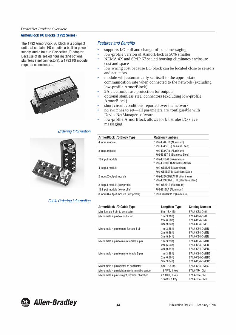
44 Publication DN-2.5 - February 1998
DeviceNet Product OverviewArmorBlock I/O Blocks (1792 Series)
Features and Benefits• supports I/O poll and change-of-state messaging• low-profile version of ArmorBlock is 50% smaller• NEMA 4X and 6P/IP 67 sealed housing eliminates enclosure
cost and space• low wiring cost because I/O block can be located close to sensors
and actuators• module will automatically set itself to the appropriate
communication rate when connected to the network (excluding low-profile ArmorBlock)
• 2A electronic fuse protection for outputs• optional stainless steel connectors (excluding low-profile
ArmorBlock)• short circuit conditions reported over the network• no switches to set—all parameters are configurable with
DeviceNetManager software• low-profile ArmorBlock allows for bit strobe I/O slave
messaging
Ordering Information
Cable Ordering information
The 1792 ArmorBlock I/O block is a compact unit that contains I/O circuits, a built-in power supply, and a built-in DeviceNet I/O adapter. Because of its sealed housing (and optional stainless steel connectors), a 1792 I/O module requires no enclosure.
ArmorBlock I/O Block Type Catalog Numbers4 input module 1792-IB4AT B (Aluminum)
1792-IB4ST B (Stainless Steel)
8 input module 1792-IB8AT B (Aluminum)1792-IB8ST B (Stainless Steel)
16 input module 1792-IB16AT B (Aluminum)1792-IB16ST B (Stainless Steel)
4 output module 1792-OB4EAT B (Aluminum)1792-OB4EST B (Stainless Steel)
2 input/2 output module 1792-IB2XOB2EAT B (Aluminum)1792-IB2XOB2EST B (Stainless Steel)
8 output module (low profile) 1792-OB8PLP (Aluminum)
16 input module (low profile) 1792-IB16LP (Aluminum)
8 input/8 output module (low profile) 1792IB8XOB8PLP (Aluminum)
ArmorBlock I/O Cable Type Length or Type Catalog NumberMini female 3 pin to conductor 5m (16.41ft) 871A-CS3-DN5
Micro male 4 pin to conductor 1m (3.28ft)2m (6.56ft)3m (9.84ft)
871A-CS4-DM1871A-CS4-DM2871A-CS4-DM3
Micro male 4 pin to mini female 4 pin 1m (3.28ft)2m (6.56ft)3m (9.84ft)
871A-CS4-DM1N871A-CS4-DM2N871A-CS4-DM3N
Micro male 4 pin to micro female 4 pin 1m (3.28ft)2m (6.56ft)3m (9.84ft)
871A-CS4-DM1D871A-CS4-DM2D871A-CS4-DM3D
Micro male 4 pin to micro female 5 pin 1m (3.28ft)2m (6.56ft)3m (9.84ft)
871A-CS4-DM1D5871A-CS4-DM2D5871A-CS4-DM3D5
Micro male 4 pin splitter to conductor 5m (16.41ft) 871A-CS4-DM5X
Micro male 4 pin right angle terminal chamber 18 AWG, 1 key 871A-TR4-DM
Micro male 4 pin straight terminal chamber 22 AWG, 1 key18AWG, 1 key
871A-TS4-DM871A-TS4-DM1
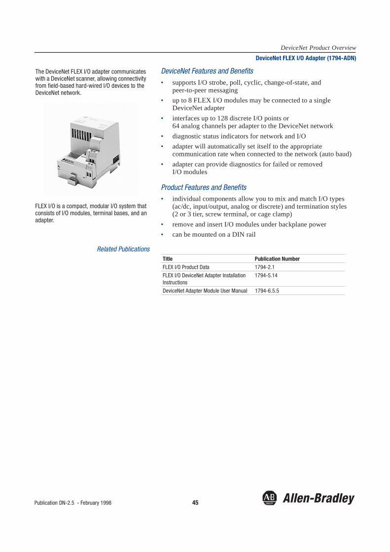
Publication DN-2.5 - February 1998 45
DeviceNet Product OverviewDeviceNet FLEX I/O Adapter (1794-ADN)
DeviceNet Features and Benefits• supports I/O strobe, poll, cyclic, change-of-state, and
peer-to-peer messaging• up to 8 FLEX I/O modules may be connected to a single
DeviceNet adapter• interfaces up to 128 discrete I/O points or
64 analog channels per adapter to the DeviceNet network• diagnostic status indicators for network and I/O • adapter will automatically set itself to the appropriate
communication rate when connected to the network (auto baud)• adapter can provide diagnostics for failed or removed
I/O modules
Product Features and Benefits• individual components allow you to mix and match I/O types
(ac/dc, input/output, analog or discrete) and termination styles (2 or 3 tier, screw terminal, or cage clamp)
• remove and insert I/O modules under backplane power• can be mounted on a DIN rail
Related Publications
The DeviceNet FLEX I/O adapter communicates with a DeviceNet scanner, allowing connectivity from field-based hard-wired I/O devices to the DeviceNet network.
FLEX I/O is a compact, modular I/O system that consists of I/O modules, terminal bases, and an adapter.
Title Publication NumberFLEX I/O Product Data 1794-2.1
FLEX I/O DeviceNet Adapter Installation Instructions
1794-5.14
DeviceNet Adapter Module User Manual 1794-6.5.5
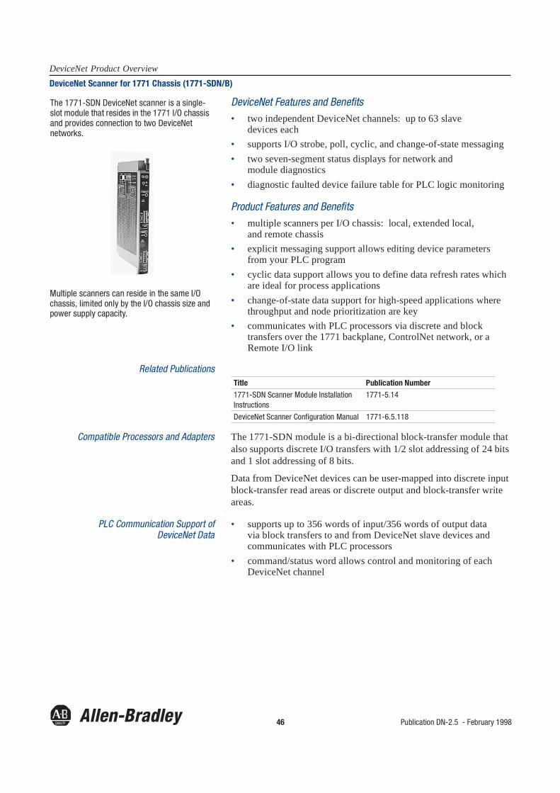
46 Publication DN-2.5 - February 1998
DeviceNet Product OverviewDeviceNet Scanner for 1771 Chassis (1771-SDN/B)
DeviceNet Features and Benefits• two independent DeviceNet channels: up to 63 slave
devices each• supports I/O strobe, poll, cyclic, and change-of-state messaging• two seven-segment status displays for network and
module diagnostics• diagnostic faulted device failure table for PLC logic monitoring
Product Features and Benefits• multiple scanners per I/O chassis: local, extended local,
and remote chassis• explicit messaging support allows editing device parameters
from your PLC program• cyclic data support allows you to define data refresh rates which
are ideal for process applications• change-of-state data support for high-speed applications where
throughput and node prioritization are key• communicates with PLC processors via discrete and block
transfers over the 1771 backplane, ControlNet network, or a Remote I/O link
Related Publications
Compatible Processors and Adapters The 1771-SDN module is a bi-directional block-transfer module that also supports discrete I/O transfers with 1/2 slot addressing of 24 bits and 1 slot addressing of 8 bits.
Data from DeviceNet devices can be user-mapped into discrete input block-transfer read areas or discrete output and block-transfer write areas.
PLC Communication Support ofDeviceNet Data
• supports up to 356 words of input/356 words of output data via block transfers to and from DeviceNet slave devices andcommunicates with PLC processors
• command/status word allows control and monitoring of each DeviceNet channel
The 1771-SDN DeviceNet scanner is a single-slot module that resides in the 1771 I/O chassis and provides connection to two DeviceNet networks.
Multiple scanners can reside in the same I/O chassis, limited only by the I/O chassis size and power supply capacity.
Title Publication Number1771-SDN Scanner Module Installation Instructions
1771-5.14
DeviceNet Scanner Configuration Manual 1771-6.5.118

Publication DN-2.5 - February 1998 47
DeviceNet Product OverviewDeviceNet Scanner for SLC Chassis (1747-SDN/B)
DeviceNet Features and Benefits• one channel per scanner: up to 63 slave devices• supports I/O strobe, poll, cyclic, and change-of-state messaging• seven-segment status display for network and
module diagnostics• diagnostic faulted device failure table for SLC logic monitoring
Product Features and Benefits• multiple scanners per SLC modular chassis• explicit messaging support allows editing device parameters
from your SLC program• cyclic data support allows you to define data refresh rates which
are ideal for process applications• change-of-state data support for high-speed applications where
throughput and node prioritization are key• communicates with SLC processors via discrete or
M1/M0 file transfers over the chassis backplane
Related Publications
Compatible Processors and Adapters You can use the 1747-SDN module in a local SLC chassis with an SLC 5/02, 5/03, or 5/04 processor in the leftmost slot.
The 1747-SDN module is compatible with the 1746-A4, -A7, -A10, and -A13 SLC chassis.
Data from DeviceNet devices can be user-mapped into discrete input and M1 read file areas, or M0 write file and discrete output areas.
SLC Communication Support ofDeviceNet Data
• supports up to 256 words of input/256 words of output data to and from DeviceNet slave devices and communicates with SLC processors via M1/M0 file transfers
• additionally supports up to 32 words to and from DeviceNet slave devices and communicates with SLC processors via discrete transfers
• can operate as a master to slave devices while operating as a slave to a remote master at the same time
The 1747-SDN DeviceNet scanner is a single-slot module that resides in the SLC modular chassis and provides connection to the DeviceNet network.
Multiple scanners can reside in the same SLC chassis, limited only by the chassis size and power supply capacity.
Title Publication Number1747-SDN Scanner ModuleInstallation Instructions
1747-5.8
DeviceNet Scanner Configuration User Manual
1747-6.5.2
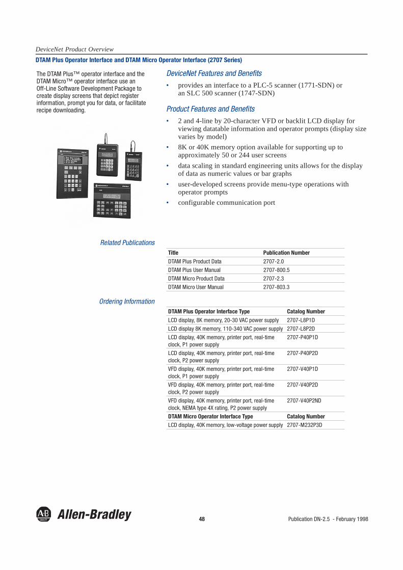
48 Publication DN-2.5 - February 1998
DeviceNet Product OverviewDTAM Plus Operator Interface and DTAM Micro Operator Interface (2707 Series)
DeviceNet Features and Benefits• provides an interface to a PLC-5 scanner (1771-SDN) or
an SLC 500 scanner (1747-SDN)
Product Features and Benefits• 2 and 4-line by 20-character VFD or backlit LCD display for
viewing datatable information and operator prompts (display size varies by model)
• 8K or 40K memory option available for supporting up to approximately 50 or 244 user screens
• data scaling in standard engineering units allows for the display of data as numeric values or bar graphs
• user-developed screens provide menu-type operations with operator prompts
• configurable communication port
Related Publications
Ordering Information
The DTAM Plus™ operator interface and the DTAM Micro™ operator interface use an Off-Line Software Development Package to create display screens that depict register information, prompt you for data, or facilitate recipe downloading.
Title Publication Number
DTAM Plus Product Data 2707-2.0
DTAM Plus User Manual 2707-800.5
DTAM Micro Product Data 2707-2.3
DTAM Micro User Manual 2707-803.3
DTAM Plus Operator Interface Type Catalog Number
LCD display, 8K memory, 20-30 VAC power supply 2707-L8P1D
LCD display 8K memory, 110-340 VAC power supply 2707-L8P2D
LCD display, 40K memory, printer port, real-time clock, P1 power supply
2707-P40P1D
LCD display, 40K memory, printer port, real-time clock, P2 power supply
2707-P40P2D
VFD display, 40K memory, printer port, real-time clock, P1 power supply
2707-V40P1D
VFD display, 40K memory, printer port, real-time clock, P2 power supply
2707-V40P2D
VFD display, 40K memory, printer port, real-time clock, NEMA type 4X rating, P2 power supply
2707-V40P2ND
DTAM Micro Operator Interface Type Catalog NumberLCD display, 40K memory, low-voltage power supply 2707-M232P3D

Publication DN-2.5 - February 1998 49
DeviceNet Product OverviewDeviceNet PCI Interface/Scanner Card (1784-PCID,1784-PCIDS)
DeviceNet Features and Benefits• interface capability for general programming, configuration, and
monitoring via a desktop computer• embedded I/O scanner functionality for use with soft control or
embedded control engines• drivers support single or multiple cards• compatible with DeviceNetManager software• ODVA compliant
Product Features and Benefits• small size (smaller than a half-size PCI card)• direct integration into Rockwell Automation’s SoftLogix5™ PC-
based controller• Windows NT, version 4.0, kernel-level driver for RSLinx™
software and IOLinx™ software included• 8K byte shared RAM for high speed data exchange• color-coded terminals for ease-of-use• UL, CSA, and CE certification• FLASH upgradable for support of future enhancements
Related PublicationTitle Publication NumberDeviceNet PCI Module Installation Instructions
1784-5.31
The DeviceNet (1784-PCID) Interface/Scanner Card is designed for the standard PCI-bus used in a majority of PCs manufactured today. The card provides users with the capability to link their PC applications to the DeviceNet network. The 1784-PCIDS is a communication interface with embedded I/O scanning capabilities.

50 Publication DN-2.5 - February 1998
DeviceNet Product OverviewDeviceView Hand-Held Configurator (2707-DNC)
DeviceNet Features and Benefits• communicates with any device on the network• allows the configuration of devices on the network• holds multiple Electronic Data Sheet (EDS) files for device
configuration in on-board memory• downloads configuration files to the unit • enhances troubleshooting on the DeviceNet network with the
diagnostic features• set node address and communication rate for devices without
hardware switches
Related Publications
Hand-Held Configurator’s Usage Modes In Enhanced Mode, you use the EDS files that you have downloaded to the hand-held configurator to provide the structure of the configuration data inside the DeviceNet device.
In Basic Mode, you communicate with a device using the native DeviceNet class, instance, and attribute addressing scheme. This mode is useful in cases where the EDS files are not available.
Ordering Information
The DeviceView™ Hand-Held Configurator encapsulates the vital functions of DeviceNetManager software into this mobile tool to configure and troubleshoot your DeviceNet network.
Title Publication NumberDeviceView Configurator Brochure 2707-1.5
DeviceView Configurator User Manual 2707-806
Hand-Held Configurator Type Catalog NumberDeviceView configurator 2707-DNC
DeviceView downloader software 2707-DP1
Network cable with bare leads, 1m (3ft) 2707-NC13
Network cable with female micro-connector, 1m (3ft) 2707-NC14
Network cable with male micro-connector, 1m (3ft) 2707-NC15
Upload/download cable 2707-NC8
120V ac power supply, ac to dc adapter 2707-PS120
220V ac power supply, ac to dc adapter 2707-PS220
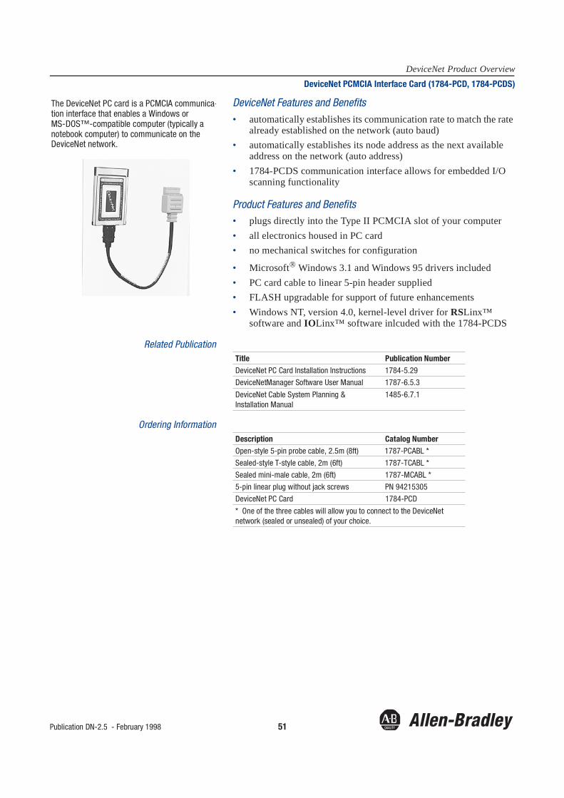
Publication DN-2.5 - February 1998 51
DeviceNet Product OverviewDeviceNet PCMCIA Interface Card (1784-PCD, 1784-PCDS)
DeviceNet Features and Benefits• automatically establishes its communication rate to match the rate
already established on the network (auto baud)• automatically establishes its node address as the next available
address on the network (auto address)• 1784-PCDS communication interface allows for embedded I/O
scanning functionality
Product Features and Benefits• plugs directly into the Type II PCMCIA slot of your computer• all electronics housed in PC card• no mechanical switches for configuration
• Microsoft® Windows 3.1 and Windows 95 drivers included• PC card cable to linear 5-pin header supplied• FLASH upgradable for support of future enhancements• Windows NT, version 4.0, kernel-level driver for RSLinx™
software and IOLinx™ software inlcuded with the 1784-PCDS
Related Publication
Ordering Information
The DeviceNet PC card is a PCMCIA communica-tion interface that enables a Windows or MS-DOS™-compatible computer (typically a notebook computer) to communicate on the DeviceNet network.
Title Publication NumberDeviceNet PC Card Installation Instructions 1784-5.29
DeviceNetManager Software User Manual 1787-6.5.3
DeviceNet Cable System Planning & Installation Manual
1485-6.7.1
Description Catalog NumberOpen-style 5-pin probe cable, 2.5m (8ft) 1787-PCABL *
Sealed-style T-style cable, 2m (6ft) 1787-TCABL *
Sealed mini-male cable, 2m (6ft) 1787-MCABL *
5-pin linear plug without jack screws PN 94215305
DeviceNet PC Card 1784-PCD
* One of the three cables will allow you to connect to the DeviceNet network (sealed or unsealed) of your choice.

52 Publication DN-2.5 - February 1998
DeviceNet Product OverviewDeviceNet RS-232 Personal Computer Interface (1770-KFD)
DeviceNet Features and Benefits• establishes the RS-232 module as a permanent node on the
network or carry it (with your PC) as a portable device from network to network for troubleshooting and maintenance
• supports point-to-point connections for downloading configura-tion information—a host computer can perform parameter or node configuration on a device
• compatible with A-B WinDNet16 protocol engine• ideal for use with DeviceNetManager software and other
WinDNet16 applications• can supply power (up to 100mA @ 12V dc) to devices for
one-on-one configuration if required• FLASH upgradable for support of future enhancements
Related Publications
Ordering Information
The RS-232 personal computer interface module connects to the RS-232 serial port of your PC-compatible laptop, desktop, notebook computer, or other serial device establishing your computer as a node on the DeviceNet network.
Title Publication NumberDeviceNet RS-232 Interface Module Installation Instructions
1770-5.6
DeviceNetManager Software User Manual 1787-6.5.3
DeviceNet Cable System Planning & Installation Manual
1485-6.7.1
Description Catalog NumberRS-232 interface module 1770-KFD
RS-232 interface module and global 9V dc power-supply adapter (only available with 1770-KFDG module)
1770-KFDG
U.S. 9V dc power-supply adapter 1787-USADPTR
Open-style 5-pin probe cable, 2.5m (8ft) 1787-PCABL
Sealed-style T-style cable, 2m (6ft) 1787-TCABL
Sealed mini-male cable, 2m (6ft) 1787-MCABL

Publication DN-2.5 - February 1998 53
DeviceNet Product OverviewOpen Controller (1747-OC)
Product Features and Benefits• chassis based system combines the reliability and form factor of a
PLC with the flexibility of personal computer technology• leverages standard PC technology for programming and interface
to communications and other options, by supporting:- PC-based operating systems—both commercial and
embedded- PC development tools such as Microsoft/Borland C/C++- PCMCIA and PCI bus technology
• integrates a 586-class CPU and a local I/O scanner to offer:- high performance and deterministic I/O response- access to Allen-Bradley’s wide range of 1746 industrial I/O
modules• rugged, industrial packaging; field-proven chassis and
power supply• long-term product availability using modular, upgradable, add-on
options with field-installable designs
Related Documentation
The Open Controller (1747-OC) is a new PC-compatible control processor in the 1746 form factor. It can communicate with local I/O, and any standard A-B RIO.
Title Publication Number
Open Control Positioning Folder 1747-1.14
Hardware/Software Profile 1747-1.13
System Overview 1747-2.22
CD-ROM 1747-CD2-1
Selection Guide 1747-1.12
Support Profile 1747-9.14
MS-DOS and Windows NT API 1747-1.16
ControlWare Driver Interface 1747-1.15

54 Publication DN-2.5 - February 1998
DeviceNet Product OverviewDeviceNet Power Supply (1787-DNPS)
DeviceNet Features and Benefits• only power supply to be DeviceNet compliant—meets DeviceNet
power requirements• standard 3-pin IEC connector on the input, Phoenix combination
connector for DeviceNet on the output
Product Features and Benefits• UL/CSA Class 2 listed power supply• 24V dc with 5.5A @ 60°C• 115/230V selectable input• LED power indicator• flange mounted
Related PublicationTitle Publication NumberDeviceNet Cable Systems and Planning Installation Manual
1485-6.7.1
The DeviceNet Power Supply is specifically designed for the DeviceNet network.

Publication DN-2.5 - February 1998 55
DeviceNet Product OverviewDeviceNet Interface for MicroLogix, SLC and PLC DeviceNet Connectivity
DeviceNet Interface Features and Benefits• peer-to-peer messaging between MicroLogix, SLC-503, -504,
-505, PLC-5, AC-15 and other devices on DeviceNet• smart device, contains all configuration parameters• allows programming and online monitoring over DeviceNet
when used with RSLogix using RSLinx products or A.I. Series• dial in connections (via modem) allow off-site controller
management• 38.4 Kbaud RS-232 port connection provides fast throughput• 32 words of change-of-state or polled I/O data available to the
DeviceNet master• supports explicit messaging when “unowned” (I/O data is not
owned, response only)• mix high speed “local” I/O with distributed DeviceNet I/O• provides isolation between DeviceNet and the RS-232 port• powered exclusively from the DeviceNet network, which makes
installation easy
Setup/Configuration• autobaud to DeviceNet• autobaud to RS-232 port device
• 0-60o operating temperature• CE compliant for applicable directives• Class 1, Division 2, Groups A,B,C,and D
Related Publications
You can also visit the MicroLogix web site at www.abmicrologix for any related publications.
The DeviceNet Interface (1761-NET-DN1) is a new networking device from Allen-Bradley that provides enhanced DeviceNet connectivity with Allen-Bradley programmable controllers and other devices that comply with Allen-Bradley’s open DF-13 full duplex communication protocol.
Title Publication Number
DeviceNet Interface Overview 1761-1.23
DeviceNet Interface Manual 1761-6.5
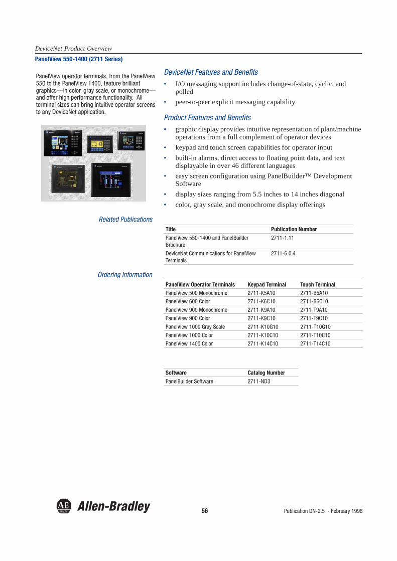
56 Publication DN-2.5 - February 1998
DeviceNet Product OverviewPanelView 550-1400 (2711 Series)
DeviceNet Features and Benefits• I/O messaging support includes change-of-state, cyclic, and
polled• peer-to-peer explicit messaging capability
Product Features and Benefits• graphic display provides intuitive representation of plant/machine
operations from a full complement of operator devices• keypad and touch screen capabilities for operator input• built-in alarms, direct access to floating point data, and text
displayable in over 46 different languages• easy screen configuration using PanelBuilder™ Development
Software• display sizes ranging from 5.5 inches to 14 inches diagonal• color, gray scale, and monochrome display offerings
Related Publications
Ordering Information
PanelView operator terminals, from the PanelView 550 to the PanelView 1400, feature brilliant graphics—in color, gray scale, or monochrome—and offer high performance functionality. All terminal sizes can bring intuitive operator screens to any DeviceNet application.
Title Publication Number
PanelView 550-1400 and PanelBuilder Brochure
2711-1.11
DeviceNet Communications for PanelView Terminals
2711-6.0.4
PanelView Operator Terminals Keypad Terminal Touch TerminalPanelView 500 Monochrome 2711-K5A10 2711-B5A10
PanelView 600 Color 2711-K6C10 2711-B6C10
PanelView 900 Monochrome 2711-K9A10 2711-T9A10
PanelView 900 Color 2711-K9C10 2711-T9C10
PanelView 1000 Gray Scale 2711-K10G10 2711-T10G10
PanelView 1000 Color 2711-K10C10 2711-T10C10
PanelView 1400 Color 2711-K14C10 2711-T14C10
Software Catalog Number
PanelBuilder Software 2711-ND3
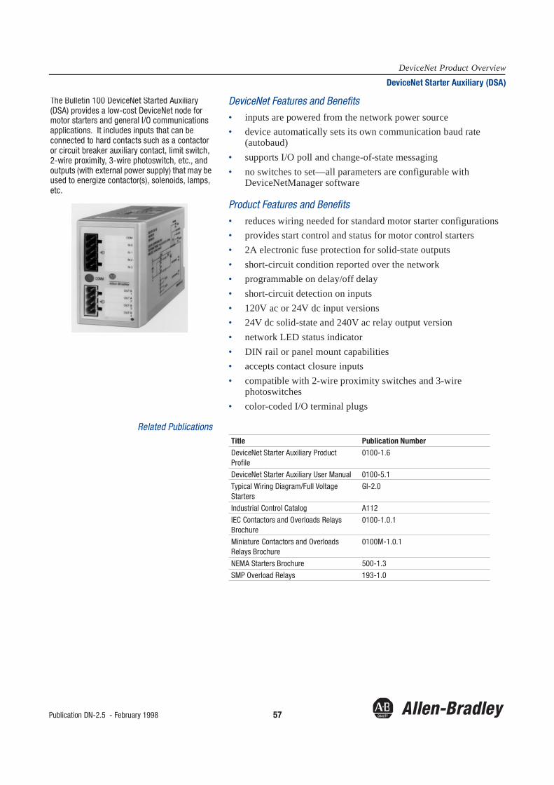
Publication DN-2.5 - February 1998 57
DeviceNet Product OverviewDeviceNet Starter Auxiliary (DSA)
DeviceNet Features and Benefits• inputs are powered from the network power source• device automatically sets its own communication baud rate
(autobaud)• supports I/O poll and change-of-state messaging• no switches to set—all parameters are configurable with
DeviceNetManager software
Product Features and Benefits• reduces wiring needed for standard motor starter configurations• provides start control and status for motor control starters• 2A electronic fuse protection for solid-state outputs• short-circuit condition reported over the network• programmable on delay/off delay• short-circuit detection on inputs• 120V ac or 24V dc input versions• 24V dc solid-state and 240V ac relay output version• network LED status indicator• DIN rail or panel mount capabilities• accepts contact closure inputs• compatible with 2-wire proximity switches and 3-wire
photoswitches• color-coded I/O terminal plugs
Related Publications
The Bulletin 100 DeviceNet Started Auxiliary (DSA) provides a low-cost DeviceNet node for motor starters and general I/O communications applications. It includes inputs that can be connected to hard contacts such as a contactor or circuit breaker auxiliary contact, limit switch, 2-wire proximity, 3-wire photoswitch, etc., and outputs (with external power supply) that may be used to energize contactor(s), solenoids, lamps, etc.
Title Publication NumberDeviceNet Starter Auxiliary Product Profile
0100-1.6
DeviceNet Starter Auxiliary User Manual 0100-5.1
Typical Wiring Diagram/Full Voltage Starters
GI-2.0
Industrial Control Catalog A112
IEC Contactors and Overloads Relays Brochure
0100-1.0.1
Miniature Contactors and Overloads Relays Brochure
0100M-1.0.1
NEMA Starters Brochure 500-1.3
SMP Overload Relays 193-1.0

58Publication DN-2.5 - February 1998
DeviceNet Product OverviewDeviceNet Bridge Module for ControlLogix Gateway (1756-DNB)
DeviceNet Features and Benefits• supports strobe, poll, change-of-state, and cyclic I/O data
production, as well as explicit• 512 bytes of inputs/512 bytes of outputs• single DeviceNet connection• supports slave mode operation• provides a built-in network power detection• user selectable manual configuration button for baud rate and
MAC ID• ODVA compliant• supports up to 63 device per module in the Gateway• integrated with RSLogix500 programming software and
DeviceNetManager software
Product Features and Benefits• high performance over the ControlLogix backplane• alphanumeric display for error conditions and general status• separate I/O LED for easy I/O status• Remove Insertion Under Power (RUIP) through ControlLogix• 10 position connector with color-coded terminals to avoid
miswiring• CE, UL, and CSA certified
Related Publication
As part of the ControlLogix Gateway, the DeviceNet Bridge Module allows communication between multiple DeviceNet networks over a common backplane or among multiple networks supported within the Gateway. For example, a node on one DeviceNet network can communicate through the ControlLogix Gateway to a node on another DeviceNet network. The presence of this module within the Gateway also allows communication between a node on DeviceNet and a node on another network, such as Ethernet, ControlNet or Data Highway Plus.
Title Publication NumberYour Next Logical Step for Seamless Integration ControlLogix Gateway Brochure
1756-1.1

Publication DN-2.5 - February 1998 59
DeviceNet Product OverviewDeviceNet Example Code (9240-DNEXP)
DeviceNet Features and Benefits• library with peer-to-peer (dynamic I/O) example code (code is
expository in nature to show how the protocol operates)• library with “C” coding for implementing a simple slave device• guides you in adapting a specific device and target CPU• coding supports explicit messaging, I/O (poll, bit and strobed)
change-of-state, and cyclic connections (change-of-state and cyclic support is provided for the Motorola X4 only)
• code is optimized for size and performance for two combination CAN/CPU chips:- Motorola 68HC05X4- Philips 80C592 (Intel 8051 core)
Related Publication
DeviceNet Example Code from Allen-Bradley consists of two libraries of “C” source code routines that implement various aspects of the DeviceNet protocol.
Title Publication NumberDeviceNet Example Code User Manual 9240-6.5.1

60 Publication DN-2.5 - February 1998
DeviceNet Product OverviewDeviceNet Master Library
DeviceNet Features and Benefits• includes source code, Application Programming Interface (API)
definitions, and user manual• includes a description of the overall scanner architecture• utilizes two APIs to allow easy integration into systems
containing various CAN chips, host microprocessors, and operating systems—all without extensive source code modifications
• features master I/O messaging functionality for bit-strobe, poll and change-of-state
• contains UCMM proxy• includes simulated environments to run the scanner stack on a
personal computer
Sale/Support handled through Value Add Design Partners. Contact Business Partner Programs for a list of ADPs by calling (440)646-5200.
The DeviceNet Master Library, Version 2.0, allows developers of embedded DeviceNet products to add I/O scanner functionality to their designs.

Publication DN-2.5 - February 1998 61
DeviceNet Product OverviewDeviceNet Slave Development Tools (9240-DNSDT)
DeviceNet Features and Benefits• Windows 16 bit-based software package• message builder window enables you to select various elements
from the protocol structure, add the appropriate data, and trigger the message-sending
• includes a master emulator to exercise a prototype slave under simulated runtime conditions
• contains a traffic monitor that will capture all valid traffic on the wire, as long as it is within the buffering capability limits
• compatible with PC interface cards from Huron Net Works, S-S Technologies, Softing, STZP, and Axnet
Related Publication
The DeviceNet Slave Development Tools provides three indespensable tools used during the development of DeviceNet slave devices.
Title Publication NumberDeviceNet Slave Development Tool Software User Manual
9240-6.5.2
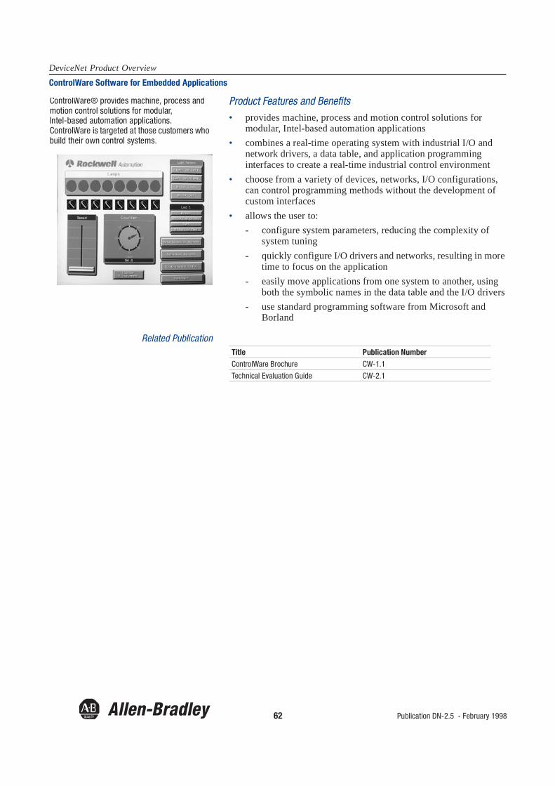
62 Publication DN-2.5 - February 1998
DeviceNet Product OverviewControlWare Software for Embedded Applications
Product Features and Benefits• provides machine, process and motion control solutions for
modular, Intel-based automation applications• combines a real-time operating system with industrial I/O and
network drivers, a data table, and application programming interfaces to create a real-time industrial control environment
• choose from a variety of devices, networks, I/O configurations, can control programming methods without the development of custom interfaces
• allows the user to:- configure system parameters, reducing the complexity of
system tuning- quickly configure I/O drivers and networks, resulting in more
time to focus on the application- easily move applications from one system to another, using
both the symbolic names in the data table and the I/O drivers- use standard programming software from Microsoft and
Borland
Related Publication
ControlWare® provides machine, process and motion control solutions for modular, Intel-based automation applications. ControlWare is targeted at those customers who build their own control systems.
Title Publication NumberControlWare Brochure CW-1.1
Technical Evaluation Guide CW-2.1
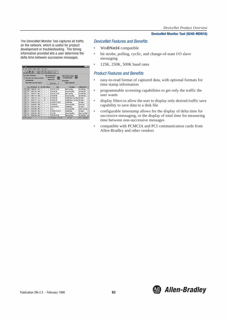
Publication DN-2.5 - February 1998 63
DeviceNet Product OverviewDeviceNet Monitor Tool (9240-MON16)
DeviceNet Features and Benefits• WinDNet16 compatible• bit strobe, polling, cyclic, and change-of-state I/O slave
messaging• 125K, 250K, 500K baud rates
Product Features and Benefits• easy-to-read format of captured data, with optional formats for
time stamp information• programmable screening capabilities to get only the traffic the
user wants• display filters to allow the user to display only desired traffic save
capability to save data to a disk file• configurable timestamp allows for the display of delta time for
successive messaging, or the display of total time for measuring time between non-successive messages
• compatible with PCMCIA and PCI communication cards from Allen-Bradley and other vendors
The DeviceNet Monitor Tool captures all traffic on the network, which is useful for product development or troubleshooting. The timing information provided lets a user determine the delta time between successive messages.

64 Publication DN-2.5 - February 1998
DeviceNet Product OverviewRSServer for DeviceNet
DeviceNet Features and Benefits• 16-bit DDE server• compatible with all Rockwell Software’s MMI and Component
products, including RSView, the WINtelligent VIEW, and the RSData Visual Basic extension
• uses the new WinDNet16™ dynamic link library to provide universal access to any of the multiple communications devices supporting DeviceNet
• tight integration with Allen-Bradley’s DeviceNetManager software.
• supports RSPortal™ which allows for the access of DeviceNet data via the Internet or an intranet
• provides highly reliable communication links from Microsoft Windows client applications to industrial devices on DeviceNet
Product Features and Benefits• simplifies data access by using parameter names form device
Electronic Data Sheet (EDS) file• diagnostics available based on server, topic, and item basis• right mouse menus are available to make operations quicker and
easier• supports all major industrial client/server DDE communication
schemes in operation today—AdvanceDDE, FastDDE, XL_Table, CF_Text
• DDE data may be addressed by EDS parameter names• topic EDS information stored and retrieved• display all parameter attributes in Advances Parameter dialog• display parameters and all other device data using Data Monitor
Requirements In order to run the RSServer for DeviceNet software, you must have Microsoft Windows (version 3.1), Windows for Workgroups (version 3.11) or Windows 95. Also, you need a suitable DeviceNet communication device that conforms to the requirements of Allen-Bradley’s WinDNet16 SDK. RSServer for DeviceNet has been tested with:
• Allen-Bradley 1770-KFD• Huron Net Works DN-PCI• S-S Technologies 5136-DN• S-S Technologies 5136-DN-PCM• Allen-Bradley 1784-PCD
RSServer is a high speed AdvanceDDE™ server that provides connectivity between DDE-aware applications and any DeviceNet Network.
* Hardware vendorsprovide the DLLscompliant withWinDNet16specification. Noupdates to RSServerfor DeviceNet required.
SMC
SMC
SMC
DeviceNet Bus
Block I/O
MotorStarters
Smart MotorControllers
SensorsPushbutton
Clusters
Message Display
Allen-Bradley
Rockwell Software
������
Wonderware
InTouch
Microsoft
Excel
Other Vendors
DDE-awareApplication
Rockwell Software
�������
�����
��������������������
�������������� DLL
NETWDN16.DLL (from WinDNet16 SDK)
��������������������
Allen-Bradley1770-KFD DLL
DLLs for otherhardware*
S-S TechnologiesHardware DLL

DeviceNet is a trademark of the Open Device Vendors Association (ODVA).
The following are trademarks of Allen-Bradley Company, Inc.: PLC, SLC, DH+, FLEX I/O, DevicePort, DeviceBox, AdaptaScan, ArmorBlock, ControlNet, DeviceNetManager, PowerTap, DeviceLink, PHOTOSWITCH, ClearSight, RediSTATION, SMP-3, SMC Dialog Plus, SMB, Accu-Stop, SCANport, 1336 PLUS, 1336 FORCE, 1336 IMPACT, SSC, DTAM Plus, DTAM Micro, DeviceView, and WinDNet16.
Ethernet is a registered trademark of Digital Equipment Corporation, Intel, and Xerox Corporation.
VALOX is a registered trademark of General Electric Company.
Microsoft is a registered trademark of Microsoft Corporation.
Windows and MS-DOS are trademarks of Microsoft Corporation.
EZLINK is a trademark of Dodge Company.
The following are trademarks of Rockwell Software, Inc.: WINtelligent, RSLogix, and RSWire.
AutoCAD is a registered trademark of Autodesk, Inc.

Publication DN-2.5 – February 1998Supersedes Publication DN-2.5 – January 1997 Copyright 1998 Rockwell International Corporation. Printed in USA


