1771-SDN/B DeviceNet Scanner Module Installation Instructions 1 Publication 1771Ć5.14 - July 1997 DeviceNet Scanner Module (Catalog Number 1771-SDN/B) Use this document as a guide to installing your 1771-SDN/B Scanner Module. To: See page: understand new features of the scanner module 2 identify related publications 3 prevent Electrostatic Discharge 3 understand the European Union Directive Compliance 4 identify scanner module features 5 prepare for installation 7 set data rate switches for channels 1 and 2 8 set I/O chassis addressing mode switches 9 set node address switches for channels 1 and 2 9 install your module into the chassis 10 understand how your module communicates with the PLC processor 13 program your PLCĆ5 processor 14 configure your module for the DeviceNet TM network 22 use the Explicit Message Program Control feature 23 troubleshoot your module 30 For this reference information See page: Specifications 34 Before you install your module you must know how to: • program and operate an Allen-Bradley PLC processor • install and configure devices on your DeviceNet network Installation Instructions Contents
The 1771-SDN/B has the following new features. For moreinformation on these features, refer to your DeviceNet ManagerSoftware User Manual (publication number 1787-6.5.3) and your1771-SDN Scanner Configuration Manual (publication number1771-6.5.118).
Change of State I/O
The scanner module can send and receive data on a change of statebasis with slave devices that also have this feature. Data is sent:
• whenever a data change occurs, or
• at a user-configurable heartbeat rate
Change of state increases system performance by reducing networktraffic, since data is only sent on an as-needed basis. UseDeviceNetManager software to activate this feature in DeviceNetproducts that support change of state.
Cyclic I/O
The scanner module can send and receive data on a cyclic basis withslave devices that also have this feature.
Cyclic I/O increases system performance by reducing networktraffic, since data is only sent at a user-configurable rate. UseDeviceNetManager software to activate this feature in DeviceNetproducts that support cyclic I/O.
Remote Scanner and Network Diagnostics
The scanner module has a node address/status indicator with anumeric display that indicates diagnostic information about themodule and network.
The scanner module duplicates this diagnostic information in word26 of the Device Failure Table and makes it available to the userPLC program.
Other New Information
Along with these new features are areas in this document that aredifferent from the previous edition. These areas are marked withchange bars (as shown to the left of this paragraph) to indicate theaddition of new or revised information.
For software configuration information, refer to yourDeviceNetManagerTM Software User Manual (publication number1787-6.5.3) and your 1771-SDN/B Scanner Configuration Manual(publication number 1771-6.5.118).
For DeviceNet cable system planning and installation information,refer to the DeviceNet Cable System Planning and InstallationManual (publication number 1485-6.7.1). If you need a copy of thismanual, fax the enclosed User Manual Request Card to1-800-576-6340. If you are outside the U.S., fax the card to1-330-723-4036.
The scanner module is sensitive to electrostatic discharge.
!ATTENTION: Electrostatic discharge can damage integrated circuits or semiconductors if you touchbackplane connector pins. Follow these guidelineswhen you handle the module:
• Touch a grounded object to discharge static potential• Wear an approved wrist-strap grounding device• Do not touch the backplane connector or
connector pins• Do not touch circuit components inside the module• If available, use a static-safe work station• When not in use, keep the module in its
If this product has the CE mark it is approved for installation withinthe European Union and EEA regions. It has been designed andtested to meet the following directives.
EMC Directive
This product is tested to meet Council Directive 89/336/EECElectromagnetic Compatibility (EMC) and the following standards,in whole or in part, documented in a technical construction file:
• EN 50081-2EMC – Generic Emission Standard, Part 2 –Industrial Environment
• EN 50082-2EMC – Generic Immunity Standard, Part 2 –Industrial Environment
This product is intended for use in an industrial environment.
Low Voltage Directive
This product is tested to meet Council Directive 73/23/EECLow Voltage, by applying the safety requirements of EN 61131–2Programmable Controllers, Part 2 – Equipment Requirements andTests.
For specific information required by EN 61131-2, see the appropriatesections in this publication, as well as the following Allen-Bradleypublications:
Make Sure That Your Module and Chassis is Compatible
The 1771-SDN Scanner Module is compatible only with the1771-A1B through 1771-A4B or later I/O chassis in anyconfiguration supported by the 1771 family.
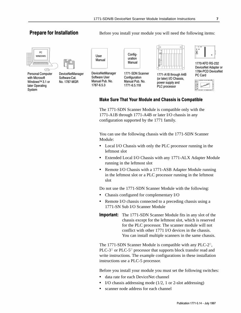
You can use the following chassis with the 1771-SDN ScannerModule:
• Local I/O Chassis with only the PLC processor running in theleftmost slot
• Extended Local I/O Chassis with any 1771-ALX Adapter Modulerunning in the leftmost slot
• Remote I/O Chassis with a 1771-ASB Adapter Module runningin the leftmost slot or a PLC processor running in the leftmostslot
Do not use the 1771-SDN Scanner Module with the following:
• Chassis configured for complementary I/O
• Remote I/O chassis connected to a preceding chassis using a1771-SN Sub I/O Scanner Module
Important: The 1771-SDN Scanner Module fits in any slot of thechassis except for the leftmost slot, which is reservedfor the PLC processor. The scanner module will notconflict with other 1771 I/O devices in the chassis.You can install multiple scanners in the same chassis.
The 1771-SDN Scanner Module is compatible with any PLC-2 ,PLC-3 or PLC-5 processor that supports block transfer read andwrite instructions. The example configurations in these installationinstructions use a PLC-5 processor.
Before you install your module you must set the following switches:
• data rate for each DeviceNet channel• I/O chassis addressing mode (1/2, 1 or 2-slot addressing)• scanner node address for each channel
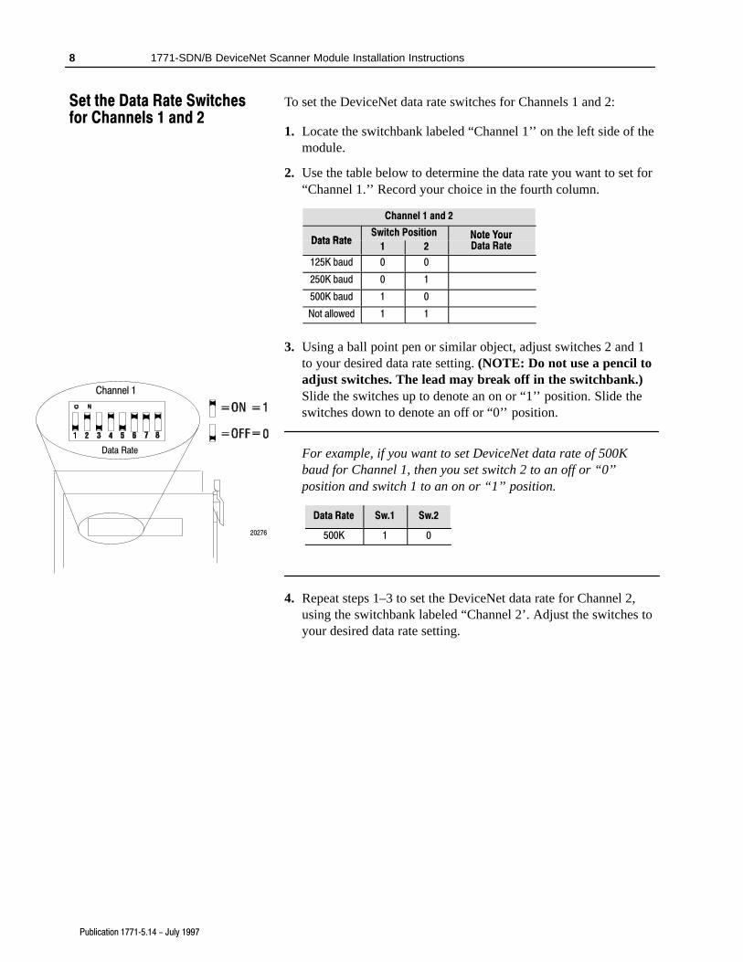
To set the DeviceNet data rate switches for Channels 1 and 2:
1. Locate the switchbank labeled “Channel 1’’ on the left side of themodule.
2. Use the table below to determine the data rate you want to set for“Channel 1.’’ Record your choice in the fourth column.
Channel 1 and 2
Data RateSwitch Position Note Your
D RData Rate
1 2Note YourData Rate
125K baud 0 0
250K baud 0 1
500K baud 1 0
Not allowed 1 1
3. Using a ball point pen or similar object, adjust switches 2 and 1to your desired data rate setting. (NOTE: Do not use a pencil toadjust switches. The lead may break off in the switchbank.)Slide the switches up to denote an on or “1’’ position. Slide theswitches down to denote an off or “0’’ position.
For example, if you want to set DeviceNet data rate of 500Kbaud for Channel 1, then you set switch 2 to an off or “0’’position and switch 1 to an on or “1’’ position.
Data Rate Sw.1 Sw.2
500K 1 0
4. Repeat steps 1–3 to set the DeviceNet data rate for Channel 2,using the switchbank labeled “Channel 2’. Adjust the switches toyour desired data rate setting.
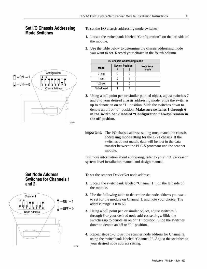
1. Locate the switchbank labeled “Configuration’’ on the left side ofthe module.
2. Use the table below to determine the chassis addressing modeyou want to set. Record your choice in the fourth column.
I/O Chassis Addressing Mode
ModeSwitch Position Note Your
M dMode
7 8Note Your
Mode
2-slot 0 0
1�slot 0 1
1/2�slot 1 0
Not allowed 1 1
3. Using a ball point pen or similar pointed object, adjust switches 7and 8 to your desired chassis addressing mode. Slide the switchesup to denote an on or “1’’ position. Slide the switches down todenote an off or “0’’ position. Make sure switches 1 through 6in the switch bank labeled “Configuration’’ always remain inthe off position.
Important: The I/O chassis address setting must match the chassisaddressing mode setting for the 1771 chassis. If theswitches do not match, data will be lost in the datatransfer between the PLC-5 processor and the scannermodule.
For more information about addressing, refer to your PLC processorsystem level installation manual and design manual.
To set the scanner DeviceNet node address:
1. Locate the switchbank labeled “Channel 1’’, on the left side ofthe module.
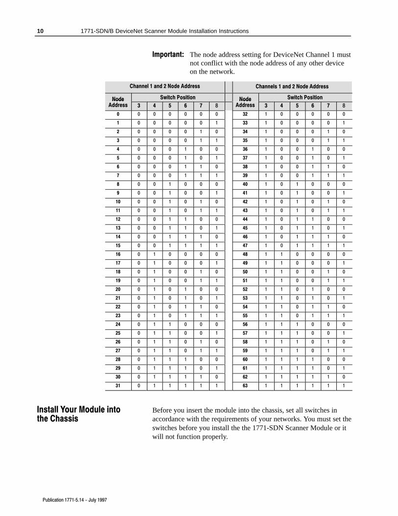
2. Use the following table to determine the node address you wantto set for the module on Channel 1, and note your choice. Theaddress range is 0 to 63.
3. Using a ball point pen or similar object, adjust switches 3through 8 to your desired node address settings. Slide theswitches up to denote an on or “1’’ position. Slide the switchesdown to denote an off or “0’’ position.
4. Repeat steps 1–3 to set the scanner node address for Channel 2,using the switchbank labeled “Channel 2”. Adjust the switches toyour desired node address setting.
Before you insert the module into the chassis, set all switches inaccordance with the requirements of your networks. You must set theswitches before you install the the 1771-SDN Scanner Module or itwill not function properly.
ATTENTION: Do not install the 1771-SDN ScannerModule with the chassis power supply on. Turn off thechassis power supply. You will disrupt backplanecommunication and may damage your module.
1. Select a slot for the module in the chassis. You may use any slotexcept the leftmost slot, which is reserved for the PLC processor.
2. Adjust the chassis’ keying bands (see figures below).
The 1771-SDN Scanner Module uses keying bands to preventplacing modules into the wrong slot. You can key any connectorin an I/O chassis to receive the module except for the leftmostconnector, which is reserved for adapter or processor modules.
keying bands
Position the keying bands in the backplane connectors tocorrespond to the key slots on the module.
19808
Place the keying bands:between 2 and 4between 22 and 24
The 1771�SDN Scanner Module is slotted in two places on therear edge of the circuit board. These slots are intended tomate with the plastic keying bands supplied with the I/Ochassis.
You can change the position of these bands if subsequent system design andrewiring makes insertion of a different type of module necessary.
I/O chassis
Scanner module
I/O chassis backplane connector
3. Insert the 1771-SDN Scanner Module into the slot you haveselected.
3. Insert the linear plug into the five-pin header forChannel 1.
20298
Five�Pin Header
DeviceNet Port 1for Channel 1
DeviceNetDrop Line
Black
Blue
White
Red
Bare
4. Repeat steps 1–3 for Channel 2, if necessary.
You have installed and wired your module. To operate the moduleyou must program the PLC processor to communicate with it. In thefollowing two sections, we describe how your module communicateswith the PLC-5 processor and how to program your processor.
The 1771-SDN scanner module uses four methods to transfer data,status and command information between the scanner and thePLC-5:
• DIO points for high-speed discrete outputs
• DIO points for high-speed discrete inputs
• BTW to send output data to the scanner
• BTR to upload input data from the scanner
Using DIO Points for High�Speed Discrete Inputs and Outputs
The following table describes chassis addressing modes and thenumber of discrete inputs and outputs assigned to the 1771-SDNScanner Module slot.
Addressing Mode Discrete Inputs Discrete Outputs
1/2�slot 24 24
1�slot 8 8
2�slot 0 0
These inputs and outputs will appear in the PLC I/O image table inthe location corresponding to the rack, group and slot the module isplugged into. Since the bits are in the I/O table, they can be forced.
For more information about chassis addressing modes, refer to yourPLC-5 processor system level installation manual.
How your ModuleCommunicates withthe PLC�5 Processor
You must program your PLC-5 processor so it communicates withthe 1771-SDN Scanner Module. Communication is possible whenyou program your processor through multiple block transferinstructions. The scanner uses the size of the block transfer to mapthe block transfer data words into the scanner’s internal data table.The scanner module accepts blocks of different sizes and knows thateach block has a different meaning.
PLC-5 block transfer instructions use one integer file in the datatable section for module location and other data to execute theinstruction. This is the control block file. The block transfer data filestores data that you want to transfer to your module (whenprogramming a block transfer write (BTW)) or from your module(when programming a block transfer read (BTR)). The address of theblock transfer data file is stored in the control block file.
You must select a separate data file for each of the block transferinstructions. You must also use separate 5-word block transfercontrol files for each of the block transfer instructions when aninteger file is used. This is not necessary when a control block fileis a BT type.
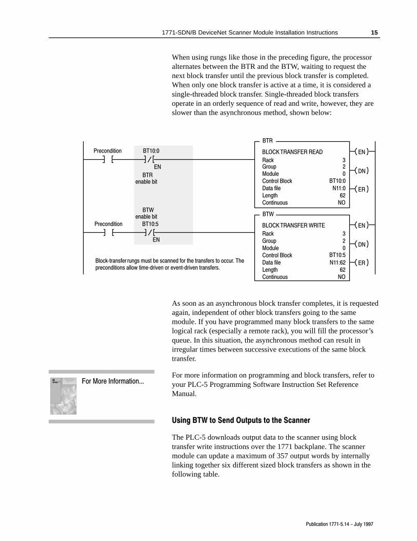
To make sure the instruction is reset after the block transfercompletes and recycles, you must use enable bits as the conditionson each rung with the PLC-5. The following figure shows a PLC-5sample program.
Important: The module does not support continuous mode blocktransfer. Set Continuous to NO for each BTW or BTR.
Precondition
ENBLOCK TRANSFER READ
RackGroupModuleControl Block
320 DN
Data fileLength
N11:062
ER
BTR
Continuous NO
ENBLOCK TRANSFER WRITE
RackGroupModuleControl Block
320
DN
Data fileLength
N11:6262
ER
BTW
Continuous NO
Block�transfer rungs must be scanned for the transfers to occur. Thepreconditions allow time�driven or event�driven transfers.
When using rungs like those in the preceding figure, the processoralternates between the BTR and the BTW, waiting to request thenext block transfer until the previous block transfer is completed.When only one block transfer is active at a time, it is considered asingle-threaded block transfer. Single-threaded block transfersoperate in an orderly sequence of read and write, however, they areslower than the asynchronous method, shown below:
Precondition
ENBLOCK TRANSFER READ
RackGroupModuleControl Block
320 DN
Data fileLength
N11:062
ER
BTR
Continuous NO
ENBLOCK TRANSFER WRITE
RackGroupModuleControl Block
320
DN
Data fileLength
N11:6262
ER
BTW
Continuous NO
Block�transfer rungs must be scanned for the transfers to occur. Thepreconditions allow time�driven or event�driven transfers.
Precondition
BTRenable bit
BTWenable bit
BT10:0
EN
BT10:5
EN
BT10:0
BT10:5
As soon as an asynchronous block transfer completes, it is requestedagain, independent of other block transfers going to the samemodule. If you have programmed many block transfers to the samelogical rack (especially a remote rack), you will fill the processor’squeue. In this situation, the asynchronous method can result inirregular times between successive executions of the same blocktransfer.
For more information on programming and block transfers, refer toyour PLC-5 Programming Software Instruction Set ReferenceManual.
Using BTW to Send Outputs to the Scanner
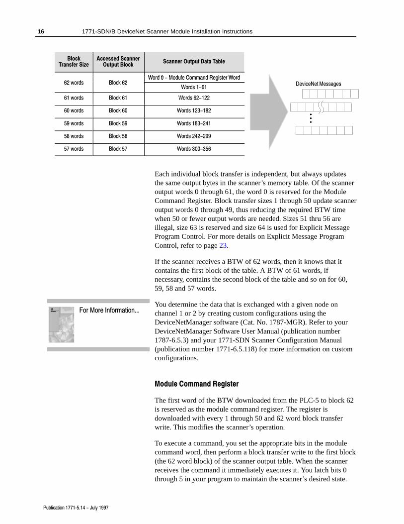
The PLC-5 downloads output data to the scanner using blocktransfer write instructions over the 1771 backplane. The scannermodule can update a maximum of 357 output words by internallylinking together six different sized block transfers as shown in thefollowing table.
Word 0 Module Command Register Word62 words Block 62
Word 0 - Module Command Register Word62 words Block 62
Words 1-61
61 words Block 61 Words 62-122
60 words Block 60 Words 123-182
59 words Block 59 Words 183-241
58 words Block 58 Words 242-299
57 words Block 57 Words 300-356
Each individual block transfer is independent, but always updatesthe same output bytes in the scanner’s memory table. Of the scanneroutput words 0 through 61, the word 0 is reserved for the ModuleCommand Register. Block transfer sizes 1 through 50 update scanneroutput words 0 through 49, thus reducing the required BTW timewhen 50 or fewer output words are needed. Sizes 51 thru 56 areillegal, size 63 is reserved and size 64 is used for Explicit MessageProgram Control. For more details on Explicit Message ProgramControl, refer to page 23.
If the scanner receives a BTW of 62 words, then it knows that itcontains the first block of the table. A BTW of 61 words, ifnecessary, contains the second block of the table and so on for 60,59, 58 and 57 words.
You determine the data that is exchanged with a given node onchannel 1 or 2 by creating custom configurations using theDeviceNetManager software (Cat. No. 1787-MGR). Refer to yourDeviceNetManager Software User Manual (publication number1787-6.5.3) and your 1771-SDN Scanner Configuration Manual(publication number 1771-6.5.118) for more information on customconfigurations.
Module Command Register
The first word of the BTW downloaded from the PLC-5 to block 62is reserved as the module command register. The register isdownloaded with every 1 through 50 and 62 word block transferwrite. This modifies the scanner’s operation.
To execute a command, you set the appropriate bits in the modulecommand word, then perform a block transfer write to the first block(the 62 word block) of the scanner output table. When the scannerreceives the command it immediately executes it. You latch bits 0through 5 in your program to maintain the scanner’s desired state.
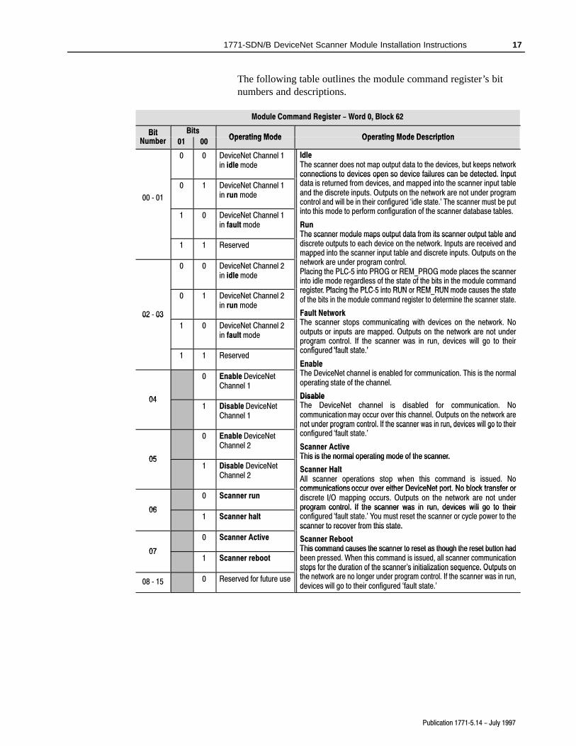
The following table outlines the module command register’s bitnumbers and descriptions.
Module Command Register - Word 0, Block 62
BitN b
BitsOperating Mode Operating Mode Description
BitNumber 01 00
Operating Mode Operating Mode Description
0 0 DeviceNet Channel 1in idle mode
IdleThe scanner does not map output data to the devices, but keeps networkconnections to devices open so device failures can be detected. Input
00 � 01
0 1 DeviceNet Channel 1in run mode
connections to devices open so device failures can be detected. Inputdata is returned from devices, and mapped into the scanner input tableand the discrete inputs. Outputs on the network are not under programcontrol and will be in their configured `idle state.' The scanner must be putinto this mode to perform config ration of the scanner database tables1 0 DeviceNet Channel 1
in fault mode
control and will be in their configured idle state. The scanner must be putinto this mode to perform configuration of the scanner database tables.
RunThe scanner module maps output data from its scanner output table and
1 1 Reserved
The scanner module maps output data from its scanner output table anddiscrete outputs to each device on the network. Inputs are received andmapped into the scanner input table and discrete inputs. Outputs on the
t k d t l0 0 DeviceNet Channel 2in idle mode
mapped into the scanner input table and discrete inputs. Outputs on thenetwork are under program control.Placing the PLC�5 into PROG or REM_PROG mode places the scannerinto idle mode regardless of the state of the bits in the module commandregister Placing the PLC 5 into RUN or REM RUN mode causes the state
02 � 03
0 1 DeviceNet Channel 2in run mode
gregister. Placing the PLC�5 into RUN or REM_RUN mode causes the stateof the bits in the module command register to determine the scanner state.
Fault NetworkTh t i ti ith d i th t k N
02 � 03
1 0 DeviceNet Channel 2in fault mode
Fault NetworkThe scanner stops communicating with devices on the network. Nooutputs or inputs are mapped. Outputs on the network are not underprogram control. If the scanner was in run, devices will go to theirconfigured `fault state '
1 1 Reserved
p g , gconfigured `fault state.'
EnableTh D i N t h l i bl d f i ti Thi i th l
04
0 Enable DeviceNetChannel 1
EnableThe DeviceNet channel is enabled for communication. This is the normaloperating state of the channel.
Disable041 Disable DeviceNet
Channel 1
DisableThe DeviceNet channel is disabled for communication. Nocommunication may occur over this channel. Outputs on the network arenot under program control. If the scanner was in run, devices will go to their
fi d `f l '
05
0 Enable DeviceNetChannel 2
not under program control. If the scanner was in run, devices will go to theirconfigured `fault state.'
Scanner ActiveThis is the normal operating mode of the scanner.05
1 Disable DeviceNetChannel 2
This is the normal operating mode of the scanner.
Scanner HaltAll scanner operations stop when this command is issued. Nocommunications occur over either DeviceNet port No block transfer or
06
0 Scanner runcommunications occur over either DeviceNet port. No block transfer ordiscrete I/O mapping occurs. Outputs on the network are not underprogram control. If the scanner was in run, devices will go to their06
1 Scanner haltprogram control. If the scanner was in run, devices will go to theirconfigured `fault state.' You must reset the scanner or cycle power to thescanner to recover from this state.
07
0 Scanner Active
scanner to recover from this state.
Scanner RebootThis command causes the scanner to reset as though the reset button had07
1 Scanner rebootThis command causes the scanner to reset as though the reset button hadbeen pressed. When this command is issued, all scanner communicationstops for the duration of the scanner's initialization sequence. Outputs onh k l d l If h i
08 � 15 0 Reserved for future use
stops for the duration of the scanner s initialization sequence. Outputs onthe network are no longer under program control. If the scanner was in run,devices will go to their configured `fault state.'
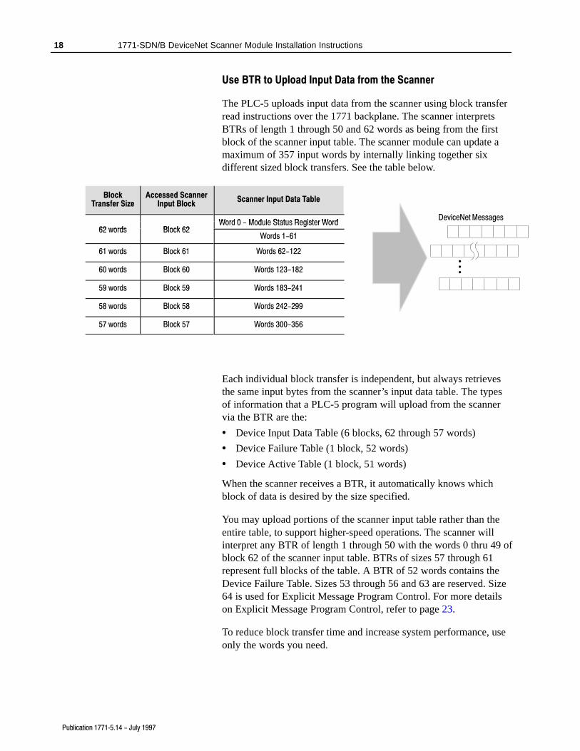
The PLC-5 uploads input data from the scanner using block transferread instructions over the 1771 backplane. The scanner interpretsBTRs of length 1 through 50 and 62 words as being from the firstblock of the scanner input table. The scanner module can update amaximum of 357 input words by internally linking together sixdifferent sized block transfers. See the table below.
BlockTransfer Size
Accessed ScannerInput Block
Scanner Input Data Table
Word 0 Module Status Register Word62 words Block 62
Word 0 - Module Status Register Word62 words Block 62
Words 1-61
61 words Block 61 Words 62-122
60 words Block 60 Words 123-182
59 words Block 59 Words 183-241
58 words Block 58 Words 242-299
57 words Block 57 Words 300-356
Each individual block transfer is independent, but always retrievesthe same input bytes from the scanner’s input data table. The typesof information that a PLC-5 program will upload from the scannervia the BTR are the:
• Device Input Data Table (6 blocks, 62 through 57 words)
• Device Failure Table (1 block, 52 words)
• Device Active Table (1 block, 51 words)
When the scanner receives a BTR, it automatically knows whichblock of data is desired by the size specified.
You may upload portions of the scanner input table rather than theentire table, to support higher-speed operations. The scanner willinterpret any BTR of length 1 through 50 with the words 0 thru 49 ofblock 62 of the scanner input table. BTRs of sizes 57 through 61represent full blocks of the table. A BTR of 52 words contains theDevice Failure Table. Sizes 53 through 56 and 63 are reserved. Size64 is used for Explicit Message Program Control. For more detailson Explicit Message Program Control, refer to page 23.
To reduce block transfer time and increase system performance, useonly the words you need.
Use the DeviceNetManager software to map data from a DeviceNetnode into the scanner input table. Data from a DeviceNet node canbe split and put into as many as four different locations in thescanner input table.
Module Status Register
In the Module Status Register (word 0, block 62), bits 0 through 5indicate to the PLC-5 the current state of the scanner module. Whena Module Command Register command is sent to the scannermodule, the respective bits are set in the Module Status Registerwhen the command executes. Depending on network load, thescanner may take several moments to detect network status changes.The bits latch on in the “on’’ state until the command clears.
Bits 6 and 7 indicate that you should read the device failure table formore specific information about which devices failed. Bits 8 and 9indicate that you should read the device autoverify table to determinewhich device has incorrect device keying or a misconfigured datasize in the scanner configuration tables. Use the DeviceNetManagersoftware to correct this error.
You can use bits 6 and 7 of the Module Status Register to enable thescanner module’s Module Command Register to react to certainconditions. An example reaction to a condition is to keep thecommunication ports in the “idle” mode until the bits clear. Whenthe bits clear, this indicates that all devices on the networks areoperational. When the devices are operational, you can put the portsin the “run’’ mode, so that output data goes to the devices.
If a device failure is detected, you can put the communication intothe ‘‘idle’’ mode, so that all devices would go into their idle state.You may tie these inputs to the Module Command Register, so thatyou may use them to adjust the operating mode of the scanner whendevices fail or go online at startup.
You can also modify your control logic to run differently tocompensate for the loss of communication with a certain node. Analarm message to alert an operator of the problem is also possible.
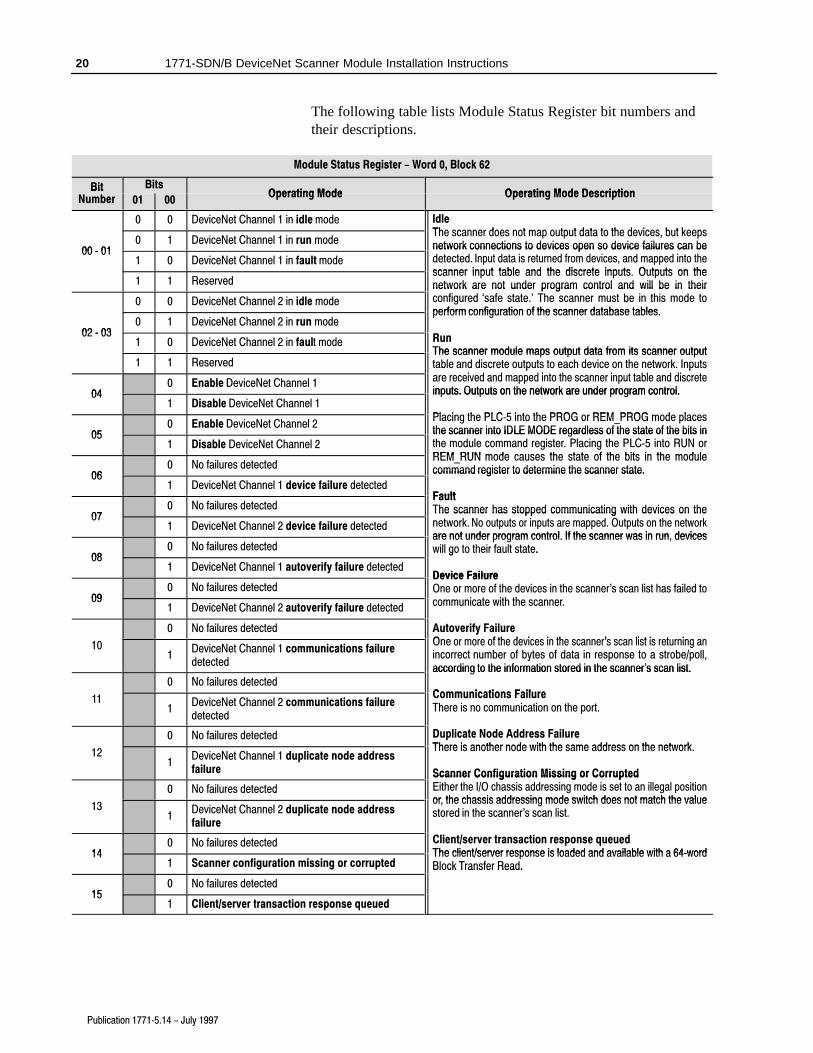
The following table lists Module Status Register bit numbers andtheir descriptions.
Module Status Register - Word 0, Block 62
BitN b
BitsOperating Mode Operating Mode Description
BitNumber 01 00
Operating Mode Operating Mode Description
0 0 DeviceNet Channel 1 in idle mode IdleThe scanner does not map output data to the devices but keeps
00 � 010 1 DeviceNet Channel 1 in run mode
The scanner does not map output data to the devices, but keepsnetwork connections to devices open so device failures can be00 � 01
1 0 DeviceNet Channel 1 in fault mode
network connections to devices open so device failures can bedetected. Input data is returned from devices, and mapped into thescanner input table and the discrete inputs Outputs on the
1 1 Reservedscanner input table and the discrete inputs. Outputs on thenetwork are not under program control and will be in their
`0 0 DeviceNet Channel 2 in idle mode
network are not under program control and will be in theirconfigured `safe state.' The scanner must be in this mode toperform configuration of the scanner database tables
02 � 030 1 DeviceNet Channel 2 in run mode
perform configuration of the scanner database tables.
R02 � 031 0 DeviceNet Channel 2 in fault mode Run
The scanner module maps output data from its scanner output1 1 Reserved
The scanner module maps output data from its scanner outputtable and discrete outputs to each device on the network. Inputs
i d d d i t th i t t bl d di t
040 Enable DeviceNet Channel 1
table and discrete outputs to each device on the network. Inputsare received and mapped into the scanner input table and discreteinputs. Outputs on the network are under program control.04
1 Disable DeviceNet Channel 1inputs. Outputs on the network are under program control.
Placing the PLC 5 into the PROG or REM PROG mode places
050 Enable DeviceNet Channel 2
Placing the PLC�5 into the PROG or REM_PROG mode placesthe scanner into IDLE MODE regardless of the state of the bits in05
1 Disable DeviceNet Channel 2the scanner into IDLE MODE regardless of the state of the bits inthe module command register. Placing the PLC�5 into RUN orREM RUN mode causes the state of the bits in the module
060 No failures detected
g gREM_RUN mode causes the state of the bits in the modulecommand register to determine the scanner state.06
1 DeviceNet Channel 1 device failure detected
command register to determine the scanner state.
Fault
070 No failures detected
FaultThe scanner has stopped communicating with devices on the
071 DeviceNet Channel 2 device failure detected
The scanner has stopped communicating with devices on thenetwork. No outputs or inputs are mapped. Outputs on the networkare not under program control If the scanner was in run devices
080 No failures detected
are not under program control. If the scanner was in run, deviceswill go to their fault state.
yOne or more of the devices in the scanner's scan list is returning anincorrect number of bytes of data in response to a strobe/poll,according to the information stored in the scanner's scan list.
0 No failures detectedaccording to the information stored in the scanner s scan list.
There is another node with the same address on the network.
Scanner Configuration Missing or Corrupted
0 No failures detected
Scanner Configuration Missing or CorruptedEither the I/O chassis addressing mode is set to an illegal positionor the chassis addressing mode switch does not match the value
131
DeviceNet Channel 2 duplicate node addressfailure
or, the chassis addressing mode switch does not match the valuestored in the scanner's scan list.
140 No failures detected Client/server transaction response queued
The client/server response is loaded and available with a 64�word141 Scanner configuration missing or corrupted
The client/server response is loaded and available with a 64�wordBlock Transfer Read.
The Device Active Table is located in words 0–7 of a 51 word BTR.The scanner assigns one bit of the first 128 bits to each device on thenetworks. The scanner assigns one bit to consecutive DeviceAddresses.
Devices on Channel 1 are indicated by a single bit in consecutiveorder in words 0–3. Devices on Channel 2 are indicated by a singlebit in consecutive order in words 4–7.
If a bit is set, it indicates that the node is in the scanner’s scan listand has successfully communicated with the scanner. These bits arenot cleared if the slave node goes off-line. The bits are cleared byresetting the scanner.
Device Failure Table
The scanner maintains one Device Failure Table accessed with a52-word BTR. The table consists of:
• Communications Failure Bitmap – the scanner tracks devicefailures in its scan list by assigning one bit of the first 128 bits inthe table to each device on the networks. The scanner assigns onebit to consecutive Device Addresses. Devices on Channel 1 areindicated by a single bit in consecutive order in words 0–3.Devices on Channel 2 are indicated by the bits in words 4–7. If abit is set, it indicates that the node is in the scanner’s scan list andit is either not present, not communicating or failed autoverify.
• Autoverify Failure Bitmap – the scanner tracks autoverify failuresby assigning one bit of the second 128 bits in the table to eachdevice on the networks. A value of 1 in the bit position indicatesa failure is detected and a value of 0 indicates normal operation.The scanner assigns one bit to consecutive Device Addresses.Devices on Channel 1 are indicated by a single bit in consecutiveorder in words 8–11. Devices on Channel 2 are indicated by thebits in words 12–15. If a bit is set, it indicates that the device isreturning device keying or a data size that does not match thekeying or data size in the scanner configuration table.
• DeviceNet 1 Scan Counter (word 16) – the scanner increments aone-word counter whenever a scan of the DeviceNet 1 devices iscompleted. The counter rolls over when it reaches its maximumvalue.
• DeviceNet 2 Scan Counter (word 17) – the scanner increments aone-word counter whenever a scan of the DeviceNet 2 devices iscompleted. The counter rolls over when it reaches its maximumvalue.
• Device Idle State Bitmap (words 18-25, 4 words for Channel 1,four words for Channel 2) – the scanner assigns one bit toconsecutive Device Addresses. Devices on Channel 1 areindicated by a single bit in consecutive order in words 18–21.Devices on Channel 2 are indicated by the bits in words 22–25. Ifa bit is set, it indicates that the scanner received a validDeviceNet idle indication from this node. A device in idle modedoes not return updated I/O data to the scanner because thedevice is not in its run mode.
• Node Address/Status Indicator (word 26) – Channel 1 andChannel 2 node address and scanner diagnostic information iscopied to the low and high bytes of Word 26, respectively. Thedescriptions of these codes are listed on page 31.
• 25 words of pad data (zeroes, words 27–51), to complete thetable for a total of 52 words.
To operate your 1771-SDN Scanner Module, you must configure thetwo tables listed below, using the DeviceNetManager software (cat.no. 1787-MGR). For more information, refer to yourDeviceNetManager for Windows Software User Manual (publication1787-6.5.3) and your 1771-SDN Scanner Configuration Manual(publication 1771-6.5.118).
Configure this table: To:
Scanner Configuration Table
Control how the scanner gathers DeviceNet messages.The information you configure for this table includes:
• frequency of background poll messages on eachDeviceNet channel
• DeviceNet port disable/enable
Scan List Table
Use the information gathered from the scan list table tomap the I/O data between the scanner's I/O data tableand DeviceNet nodes. A device must have a configurationtable entry in the scanner's database before its I/O mes�sages are mapped to the PLC. The information you con�figure for this table includes:
• the size of data in each node's DeviceNet messages
• location of a device's data in the data tables that aretransferred to and from the PLC
Use the Explicit Message Program Control feature to configuredevice parameters on your DeviceNet network via the ladder logicprogram in the PLC-5 processor that is controlling these devices.
You can use Explicit Message Program Control only with devicesthat are slaves of your 1771-SDN Scanner Module. These slavedevices must be mapped in the scanner module’s scan list.
Use the Explicit Message Program Control feature to:
• transmit configuration data from your scanner module to its slavedevices on your DeviceNet network
• receive status and diagnostics from these devices on yourDeviceNet network
• make runtime adjustments to device parameters according tochanging conditions detected by your processor
How the Explicit Message Program Control Feature Works
DeviceNetdrop line
DeviceNet trunk line
Master's ExplicitRequest
Slave's ExplicitResponse 1203�GK5
CommunicationAdapter
Block Transfer Write file (64 words)(sent from processor to scanner module)
Block Transfer Read file (64 words)(sent from scanner module to processor)
Explicit Message - A message used to transmitcommands, data, requests for data or responses.The message is sent from a client on the Device�Net network to a server on thatnetwork.
Request - An explicit message sent by a clientto a server requesting the server to performa function.
Response - An explicit message sent by a serverto a client in response to the client's request. Forevery request issued, there is a response.
4
1305 ACdrive
5
Block Transfer Read fileis completed. TXID'sare deleted and can bereused.
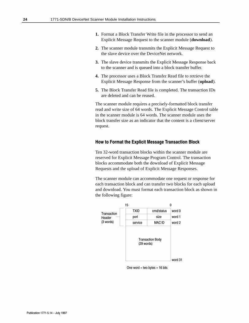
1. Format a Block Transfer Write file in the processor to send anExplicit Message Request to the scanner module (download).
2. The scanner module transmits the Explicit Message Request tothe slave device over the DeviceNet network.
3. The slave device transmits the Explicit Message Response backto the scanner and is queued into a block transfer buffer.
4. The processor uses a Block Transfer Read file to retrieve theExplicit Message Response from the scanner’s buffer (upload).
5. The Block Transfer Read file is completed. The transaction IDsare deleted and can be reused.
The scanner module requires a precisely-formatted block transferread and write size of 64 words. The Explicit Message Control tablein the scanner module is 64 words. The scanner module uses theblock transfer size as an indicator that the content is a client/serverrequest.
How to Format the Explicit Message Transaction Block
Ten 32-word transaction blocks within the scanner module arereserved for Explicit Message Program Control. The transactionblocks accommodate both the download of Explicit MessageRequests and the upload of Explicit Message Responses.
The scanner module can accommodate one request or response foreach transaction block and can transfer two blocks for each uploadand download. You must format each transaction block as shown inthe following figure:
• transaction header – contains information that identifies thetransaction to the scanner and processor
• transaction body – in a request, this contains the DeviceNetClass, Instance, Attribute and Service Data portion of thetransaction. In a response, this contains only the responsemessage.
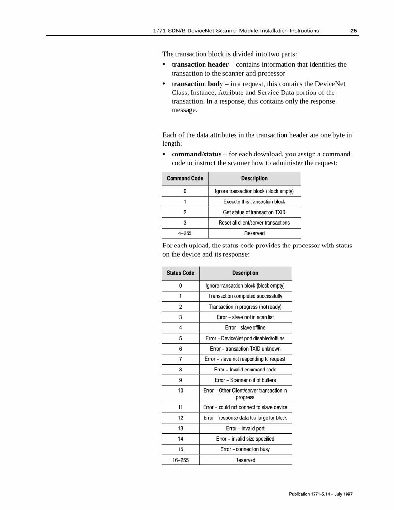
Each of the data attributes in the transaction header are one byte inlength:
• command/status – for each download, you assign a commandcode to instruct the scanner how to administer the request:
Command Code Description
0 Ignore transaction block (block empty)
1 Execute this transaction block
2 Get status of transaction TXID
3 Reset all client/server transactions
4-255 Reserved
For each upload, the status code provides the processor with statuson the device and its response:
Status Code Description
0 Ignore transaction block (block empty)
1 Transaction completed successfully
2 Transaction in progress (not ready)
3 Error - slave not in scan list
4 Error - slave offline
5 Error - DeviceNet port disabled/offline
6 Error - transaction TXID unknown
7 Error - slave not responding to request
8 Error - Invalid command code
9 Error - Scanner out of buffers
10 Error - Other Client/server transaction inprogress
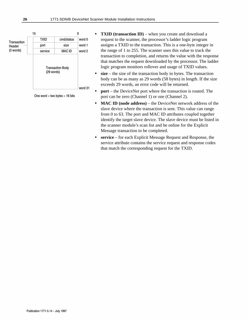
• TXID (transaction ID) – when you create and download arequest to the scanner, the processor’s ladder logic programassigns a TXID to the transaction. This is a one-byte integer inthe range of 1 to 255. The scanner uses this value to track thetransaction to completion, and returns the value with the responsethat matches the request downloaded by the processor. The ladderlogic program monitors rollover and usage of TXID values.
• size – the size of the transaction body in bytes. The transactionbody can be as many as 29 words (58 bytes) in length. If the sizeexceeds 29 words, an error code will be returned.
• port – the DeviceNet port where the transaction is routed. Theport can be zero (Channel 1) or one (Channel 2).
• MAC ID (node address) – the DeviceNet network address of theslave device where the transaction is sent. This value can rangefrom 0 to 63. The port and MAC ID attributes coupled togetheridentify the target slave device. The slave device must be listed inthe scanner module’s scan list and be online for the ExplicitMessage transaction to be completed.
• service – for each Explicit Message Request and Response, theservice attribute contains the service request and response codesthat match the corresponding request for the TXID.
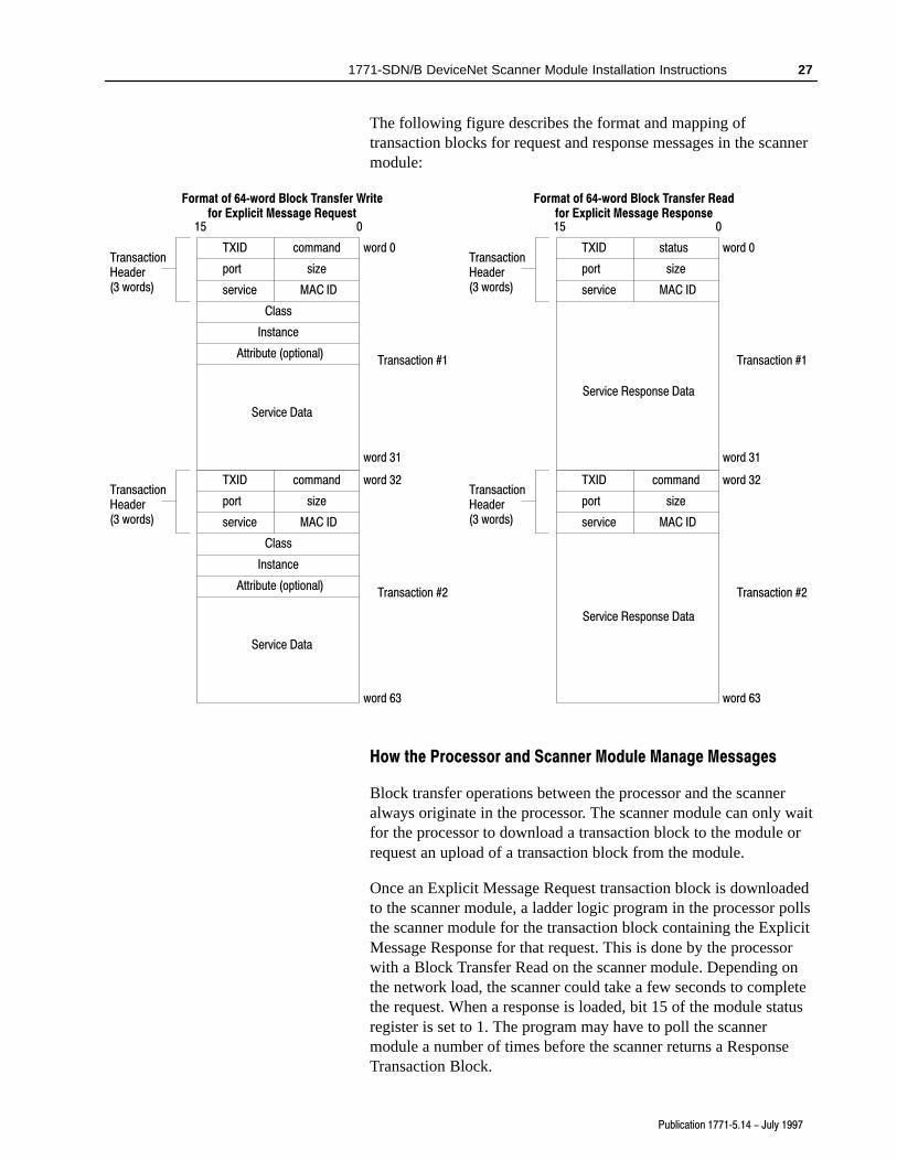
The following figure describes the format and mapping oftransaction blocks for request and response messages in the scannermodule:
service
port
TXID command
size
MAC ID
Service Data
word 0TransactionHeader(3 words)
word 31
15 0
Class
Instance
Attribute (optional)Transaction #1
service
port
TXID command
size
MAC ID
Service Data
word 32TransactionHeader(3 words)
word 63
Class
Instance
Attribute (optional)Transaction #2
Format of 64�word Block Transfer Writefor Explicit Message Request
service
port
TXID status
size
MAC ID
Service Response Data
word 0TransactionHeader(3 words)
word 31
15 0
Transaction #1
service
port
TXID command
size
MAC ID
Service Response Data
word 32TransactionHeader(3 words)
word 63
Transaction #2
Format of 64�word Block Transfer Readfor Explicit Message Response
How the Processor and Scanner Module Manage Messages
Block transfer operations between the processor and the scanneralways originate in the processor. The scanner module can only waitfor the processor to download a transaction block to the module orrequest an upload of a transaction block from the module.
Once an Explicit Message Request transaction block is downloadedto the scanner module, a ladder logic program in the processor pollsthe scanner module for the transaction block containing the ExplicitMessage Response for that request. This is done by the processorwith a Block Transfer Read on the scanner module. Depending onthe network load, the scanner could take a few seconds to completethe request. When a response is loaded, bit 15 of the module statusregister is set to 1. The program may have to poll the scannermodule a number of times before the scanner returns a ResponseTransaction Block.
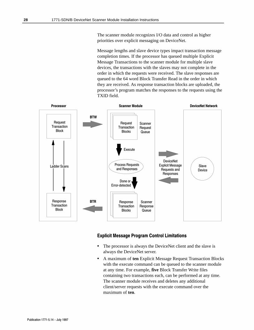
The scanner module recognizes I/O data and control as higherpriorities over explicit messaging on DeviceNet.
Message lengths and slave device types impact transaction messagecompletion times. If the processor has queued multiple ExplicitMessage Transactions to the scanner module for multiple slavedevices, the transactions with the slaves may not complete in theorder in which the requests were received. The slave responses arequeued to the 64 word Block Transfer Read in the order in whichthey are received. As response transaction blocks are uploaded, theprocessor’s program matches the responses to the requests using theTXID field.
RequestTransaction
Block
ResponseTransaction
Block
Ladder Scans Process Requestsand Responses
RequestTransaction
Blocks
ResponseTransaction
Blocks
ScannerResponse
Queue
ScannerRequestQueue
Execute
Done orError�detected
BTR
BTW
Processor Scanner Module
DeviceNetExplicit Message
Requests andResponses
DeviceNet Network
SlaveDevice
Explicit Message Program Control Limitations
• The processor is always the DeviceNet client and the slave isalways the DeviceNet server.
• A maximum of ten Explicit Message Request Transaction Blockswith the execute command can be queued to the scanner moduleat any time. For example, five Block Transfer Write filescontaining two transactions each, can be performed at any time.The scanner module receives and deletes any additionalclient/server requests with the execute command over themaximum of ten.
As transactions are removed from the queue and response transactionblocks are returned to the processor, additional transaction blockscan be issued in their place, as long as the total does not exceed ten.
• The scanner module supports two transaction blocks per uploadand download.
• Request Transaction Blocks can only be queued for slave devicesof the scanner module and must appear in the scanner module’sscan list.
• If a slave device is not communicating at the time the scannermodule processes its Request Transaction Block, the scannermodule will return an error status for that transaction.
• At a minimum, the scanner module supports the followingDeviceNet services in Request Transaction Blocks:
Service Name: Service Code: Example:
Get_Attribute_Single 0E hex Upload a single parameter value froma device
Set_Attribute_Single 10 hex Download a single parameter valueto a device
Get_Attribute_All 01 hex Upload all parameter values from adevice
Set_Attribute_All 02 hex Download all parameter values to adevice
• Continuous Block Transfers of 64 words are not supported.
• All transaction blocks are processed, therefore, any unusedtransaction blocks must be left blank.
• Client/Server commands and requests with transaction IDs thatare in use are deleted by the scanner module.
• If a slave device returns a DeviceNet error in response to therequest downloaded from the processor, the scanner recognizesthe error as a successful transaction (status code =1).
A failure to respond to the request within the number of retries ortimeout period specified for the Explicit Message Connection isrecognized by the scanner module as an error. The error code isreturned in the status attribute of the transaction header.
Channels 1 and 2 each have a bicolor (green/red) network statusindicator. The following table provides troubleshooting informationabout the Channel 1 and 2 communication links.
If your indicator is: Then: Which Indicates: Take this action:
Off The device has no poweror the channel isdisabled forcommunication due tobus off condition, loss ofnetwork power, or hasbeen intentionallydisabled.
The channel is disabled for DeviceNetcommunication.
Power�up the scanner, provide networkpower to channel, and make sure channel isenabled in both the scanner configurationtable and module command word.
Flashing Green The two�digit numericdisplay for the channelindicates an error codethat provides moreinformation about thecondition of the channel.
The channel is enabled but nocommunication is occurring.
Configure scan list table for channel to adddevices.
Solid Green There's normaloperation.
All slave devices in the scan list table arecommunicating normally with the scanner.
Do nothing.
Solid Red The communicationschannel has failed. The two digit numericdisplay for the channeldisplays an error codethat provides moreinformation about thecondition of the channel.
The scanner may be defective.
Reset module. If failures continue, replacemodule.
Flashing Red The two�digit numericdisplay for the channeldisplay an error codethat provides moreinformation about thecondition of the channel.
At least one of the slave devices in thescanner's scan list table has failed tocommunicate with the scanner.
The network has faulted.
Examine the failed device and check thescan list table for accuracy.
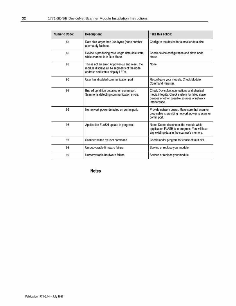
Your 1771-SDN Scanner Module has a node address/status indicatorthat uses numeric displays to indicate diagnostic information aboutyour module. The display flashes at approximately 1 secondintervals, depending on network traffic. The following tablesummarizes the meanings of the numeric codes.
Numeric Code: Description: Take this action:
Network AddressDisplays
0 � 63
Normal operation. The numeric display matchesthe scanner's node address on the DeviceNetnetwork.
Do nothing.
70 Scanner failed Duplicate Node Address check Change the scanner channel address to anotheravailable one. The node address you selected isalready in use on that channel.
71 Illegal data in scan list table (node numberalternately flashes).
Reconfigure the scan list table and remove anyillegal data.
73 Device's identity information does not matchelectronic key in scan list table entry (nodenumber alternately flashes).
Verify that the correct device is at this nodenumber. Make sure that the device at the flashingnode address matches the desired electronic key(vendor, product code, product type).
74 Data overrun on port detected. Modify your configuration and check for invaliddata. Check network communication traffic.
75 No scan list is active in the module. Enter a scan list.
76 No direct network traffic for scanner detected. None. The scanner hears other networkcommunication.
77 Data size expected by the device does not matchscan list entry (node number alternately flashes).
Reconfigure your module for the correct transmitand receive data sizes.
78 Slave device in scan list table does not exist(node number alternately flashes).
Add the device to the network, or delete the scanlist entry for that device.
79 Scanner has failed to transmit a message. Make sure that your module is connected to avalid network.
Check for disconnected cables.
80 Scanner is in IDLE mode. Put PLC�5 in RUN mode. Enable RUN bit inmodule command register.
81 Scanner is in FAULT mode. Check ladder program for cause of fault bits.
82 Error detected in sequence of fragmented I/Omessages from device (node number alternatelyflashes).
Check scan list table entry for slave device tomake sure that input and output data lengths arecorrect. Check slave device configuration.
83 Slave device is returning error responses whenscanner attempts to communicate with it (nodenumber alternately flashes).
Check accuracy of scan list table entry. Checkslave device configuration. Slave device may bein another master's scan list. Reboot slavedevice.
84 Scanner is initializing the DeviceNet channel. None. This code clears itself once scannerattempts to initialize all slave devices on thechannel.
85 Data size larger than 255 bytes (node numberalternately flashes).
Configure the device for a smaller data size.
86 Device is producing zero length data (idle state)while channel is in Run Mode.
Check device configuration and slave nodestatus.
88 This is not an error. At power�up and reset, themodule displays all 14 segments of the nodeaddress and status display LEDs.
None.
90 User has disabled communication port Reconfigure your module. Check ModuleCommand Register.
91 Bus�off condition detected on comm port.Scanner is detecting communication errors.
Check DeviceNet connections and physicalmedia integrity. Check system for failed slavedevices or other possible sources of networkinterference.
92 No network power detected on comm port. Provide network power. Make sure that scannerdrop cable is providing network power to scannercomm port.
95 Application FLASH update in progress. None. Do not disconnect the module whileapplication FLASH is in progress. You will loseany existing data in the scanner's memory.
97 Scanner halted by user command. Check ladder program for cause of fault bits.
98 Unrecoverable firmware failure. Service or replace your module.
99 Unrecoverable hardware failure. Service or replace your module.
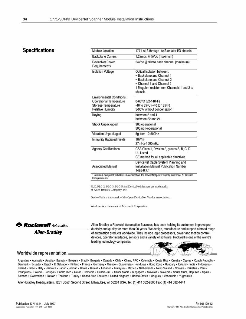
Module Location 1771�A1B through �A4B or later I/O chassis
Backplane Current 1.2amps @ 5Vdc (maximum)
DeviceNet PowerRequirements1
24Vdc @ 90mA each channel (maximum)
Isolation Voltage Optical Isolation between:• Backplane and Channel 1• Backplane and Channel 2• Channel 1 and Channel 21 Megohm resistor from Channels 1 and 2 tochassis
Agency Certifications CSA Class 1, Division 2, groups A, B, C, DUL ListedCE marked for all applicable directives
Associated ManualDeviceNet Cable System Planning andInstallation Manual Publication Number1485�6.7.1
1To remain compliant with UL/CSA certification, the DeviceNet power supply must meet NEC ClassII requirements.
PLC, PLC-2, PLC-3, PLC-5 and DeviceNetManager are trademarksof Allen-Bradley Company, Inc.
DeviceNet is a trademark of the Open DeviceNet Vendor Association.
Windows is a trademark of Microsoft Corporation.
Publication 1771�5.14 - July 1997Supersedes Publication 1771�5.14 - July 1996
PN 955129�52Copyright 1997 Allen�Bradley Company, Inc. Printed in USA
Allen�Bradley, a Rockwell Automation Business, has been helping its customers improve pro�ductivity and quality for more than 90 years. We design, manufacture and support a broad rangeof automation products worldwide. They include logic processors, power and motion controldevices, operator interfaces, sensors and a variety of software. Rockwell is one of the world'sleading technology companies.
Worldwide representation.
Argentina • Australia • Austria • Bahrain • Belgium • Brazil • Bulgaria • Canada • Chile • China, PRC • Colombia • Costa Rica • Croatia • Cyprus • Czech Republic •Denmark • Ecuador • Egypt • El Salvador • Finland • France • Germany • Greece • Guatemala • Honduras • Hong Kong • Hungary • Iceland • India • Indonesia •Ireland • Israel • Italy • Jamaica • Japan • Jordan • Korea • Kuwait • Lebanon • Malaysia • Mexico • Netherlands • New Zealand • Norway • Pakistan • Peru •Philippines • Poland • Portugal • Puerto Rico • Qatar • Romania • Russia-CIS • Saudi Arabia • Singapore • Slovakia • Slovenia • South Africa, Republic • Spain •Sweden • Switzerland • Taiwan • Thailand • Turkey • United Arab Emirates • United Kingdom • United States • Uruguay • Venezuela • Yugoslavia
Allen�Bradley Headquarters, 1201 South Second Street, Milwaukee, WI 53204 USA, Tel: (1) 414 382�2000 Fax: (1) 414 382�4444