71
Dewatering Prof. Jie Han, Ph.D., PE The University of Kansas
| Date post: | 28-Oct-2015 |
| Category: |
Documents |
| Upload: | nasrullahk24 |
| View: | 54 times |
| Download: | 2 times |

Dewatering
Prof. Jie Han, Ph.D., PEThe University of Kansas

Outline of Presentation
• Introduction• Applications• Design• Examples

Introduction
Purposes for Dewatering
For construction excavations or permanent structures that are below the water table andare not waterproof or are waterproof but arenot designed to resist the hydrostatic pressure
Permanent dewatering systems are far lesscommonly used than temporary or constructiondewatering systems

Permanent Highway Below Groundwater Table
Highway

Common Dewatering Methods
Sumps, trenches, and pumps
Well points
Deep wells with submersible pumps
Sumps, Trenches, and Pumps
Handle minor amount of water inflow
The height of groundwater above the excavation bottom is relatively small (5ft or less)
The surrounding soil is relatively impermeable (such as clayey soil)

Sump Arrangement
Harris (1994)

Wet Excavations
Sump pumps are frequently used to remove surfacewater and a small infiltration of groundwater
Sumps and connecting interceptor ditches should belocated well outside the footing area and below thebottom of footing so the groundwater is not allowedto disturb the foundation bearing surface
In granular soils, it is important that fine particles notbe carried away by pumping. The sump(s) may be lined with a filter material to prevent or minimize loss of fines

Dewatering Open Excavation by Ditch and Sump
Army TM 5-818-5

Well Point Method
Multiple closely spaced wells connected by pipesto a strong pump
Multiple lines or stages of well points are required for excavations more than 15 to 20 ft below thegroundwater table

Well Point
Harris (1994)

Well Point Installation
Harris (1994)

Single Stage Well Point System
Caltrans

Single Stage Well Point System

Typical Multiple Well Point System
Johnson (1975)

Staged Ring Well Point System
Harris (1994)

Effect of Foundation Depth and Impermeable Stratum
Harris (1994)DDC = Draw-Down Curve

Deep Wells with Submersible Pumps
Pumps are placed at the bottom of the wells andthe water is discharged through a pipe connectedto the pump and run up through the well hole toa suitable discharge point
They are more powerful than well points, require a wider spacing and fewer well holes
Used alone or in combination of well points

Deep Well
Harris (1994)
Bore a hole with rotary boringmethod Insert a temporary outer casing
if necessary Place a perforated well liner Plug the well bottom Place layers of filter material
around the casing

Deep Wells with Submersible Pumps
Harris (1994)
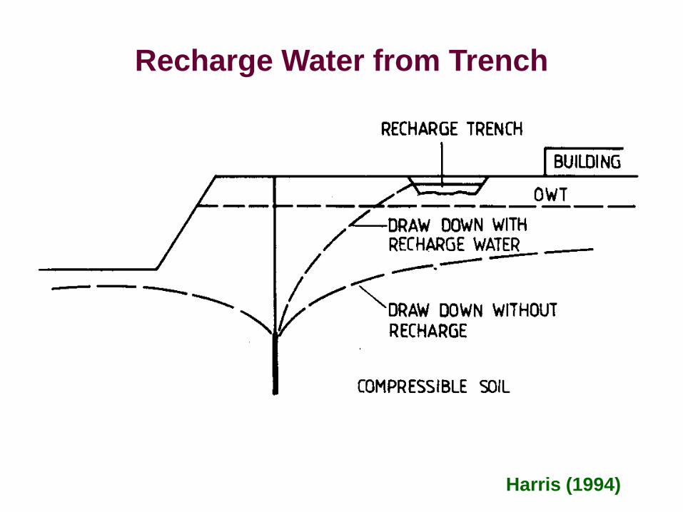
Recharge Water from Trench
Harris (1994)

Inappropriate Recharging
Harris (1994)

Recharge Water from Wells
Harris (1994)

Applicability of Dewatering Systems
Army TM 5-818-5

Applications

Permanent Groundwater Control System
Army TM 5-818-5

Deep Wells with Auxiliary Vacuum System
Army TM 5-818-5

Buoyancy Effects on Underground Structure
Xanthakos et al. (1994)

Recharge Groundwater to Prevent Settlement
Army TM 5-818-5

Sand Drains for Dewatering A Slope
Army TM 5-818-5

Grout Curtain or Cutoff Trench around An Excavation
Army TM 5-818-5

Design
Design Input Parameters
Most important input parameters for selectingand designing a dewatering system:
- the height of the groundwater above the base of the excavation
- the permeability of the ground surroundingthe excavation

Depth of Required Groundwater Lowering
The water level should be lowered to about 2 to5 ft below the base of the excavation
2 to 5ft

Methods for Permeability
Empirical formulas
Laboratory permeability tests
Borehole packer tests
Field pump tests
Accuracy
Cost

Darcy’s Law
Average velocity of flow
Lhkkiv ==
Rate (quantity) of flowA
LhkkiAq ==
Actual velocity of flow
nvva =

Typical Permeability of Soils
Soil or rock formation Range of k (cm/s) Gravel 1 - 5Clean sand 10-3 - 10-2
Clean sand and gravel mixturesMedium to coarse sandVery fine to fine sandSilty sandHomogeneous claysShaleSandstoneLimestone
10-3 - 10-1
Fractured rocks
10-2 - 10-1
10-4 - 10-3
10-5 - 10-2
10-9 - 10-7
10-11 - 10-7
10-8 - 10-4
10-7 - 10-4
10-6 - 10-2

Permeability vs.
Effective Grain Size
Army TM 5-818-5Effective Grain Size (D10) of Soil, mmC
oeffi
cien
t of H
oriz
onta
l per
mea
bilit
y of
Soi
l (k h
) x10
-4cm
/sec
Note: kh based on field pumping tests

h
QA
SoilL
Constant Head Test
hAtQLk =

Falling Head Test
Soil
AValve
h1h2
At t=t1
At t=t2dh
a
L
∆
=2
1hh
tAaLk ln

Field Pumping Test
h2h1
r2
r1
r
dr dh
h
Phreatic levelbefore pumping
Phreatic levelafter pumping
Test well
Observation wells
Impermeable layer
q

Observation Wells
NAVFAC (1982)

Permeability from Field Pumping Test
Permeability
( )22
21
21
hhr
rqk
−π
=ln
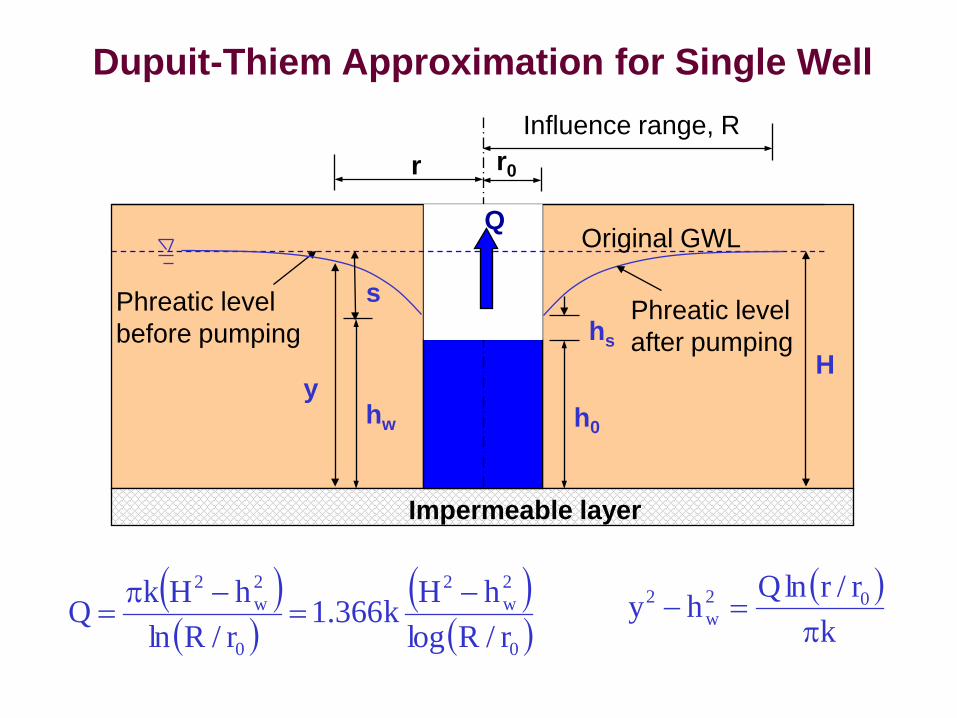
Dupuit-Thiem Approximation for Single Well
h0
hs
r0
Influence range, Rr
hw
Phreatic levelbefore pumping
Phreatic levelafter pumping
Impermeable layer
QOriginal GWL
s
( )( )
( )( )0
2w
2
0
2w
2
r/RloghHk366.1
r/RlnhHkQ −
=−π
=
Hy
( )k
r/rlnQhy 02w
2
π=−

Height of Free Discharge Surface
( )H
hHChs
20−
=
Ollos proposed a value of C = 0.5

Influence Range
( ) khH'CR w−=
Sichardt (1928)
C = 3000 for wells or 1500 to 2000 for single line well points
H, hw in meters and k in m/s
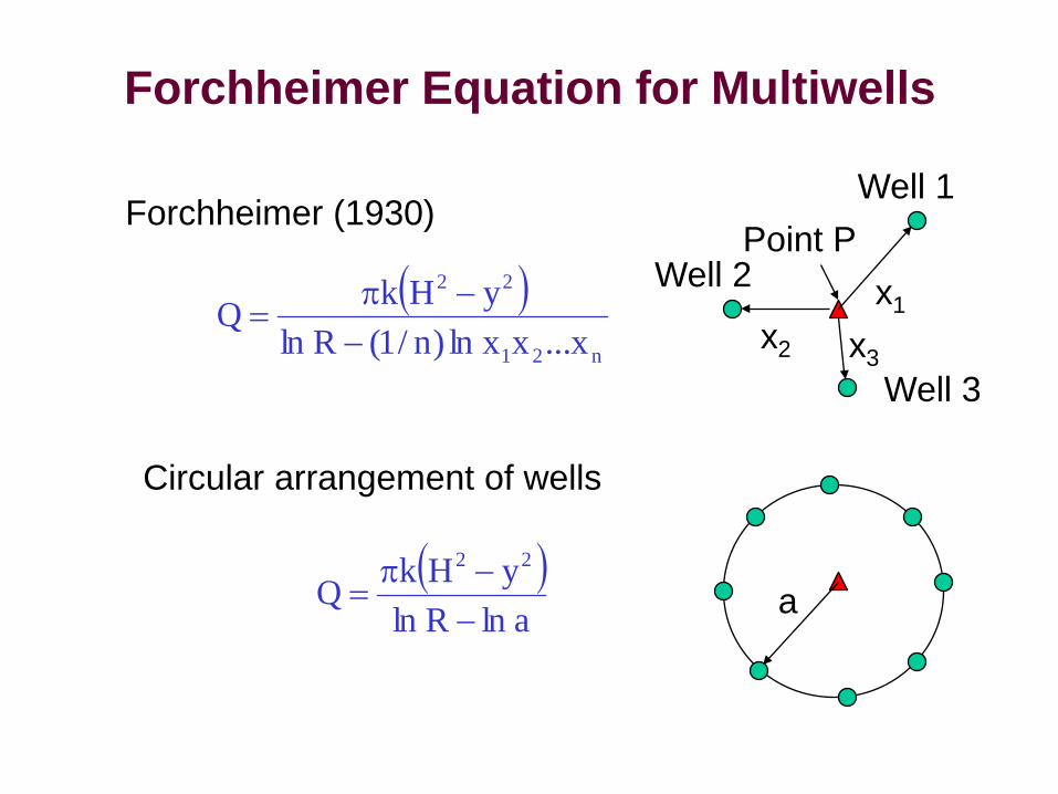
Forchheimer Equation for Multiwells
( )n21
22
x...xxln)n/1(RlnyHkQ
−−π
=
Forchheimer (1930)
x1
Well 1
Well 2
Well 3
Point P
x2 x3
a( )
alnRlnyHkQ
22
−−π
=
Circular arrangement of wells
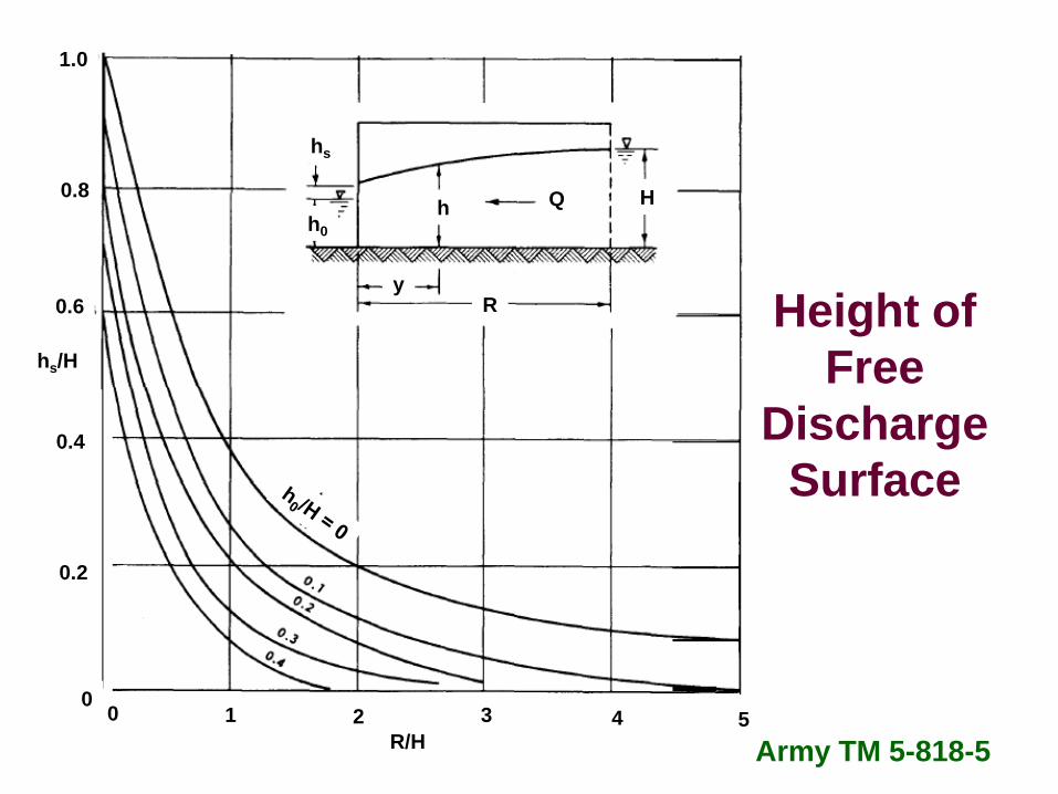
0 1 2 3 4 5R/H
0
0.4
0.2
0.6
0.8
1.0
hs/H
hs
h0h Q H
Ry
Army TM 5-818-5
Height of Free
Discharge Surface

Estimation of Flow Rate – Darcy’s Law
r0 h0H
H-h0
R
( )( )( )0
000
rRrRhHhHk571.1Q
−++−
=
Cedergren (1967)

Estimation of Flow Rate – Well Formulas
r0 h0H
H-h0
R
( )0
20
2
r/RloghHk366.1Q −
=
Cedergren (1967)
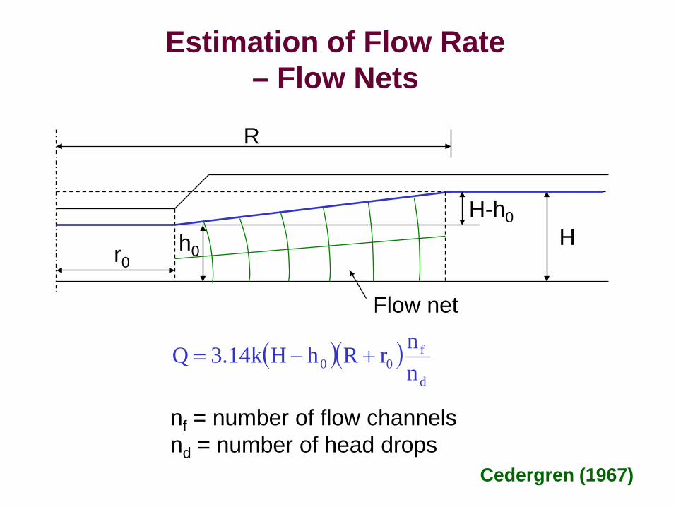
Estimation of Flow Rate – Flow Nets
r0h0
HH-h0
R
( )( )d
f00 n
nrRhHk14.3Q +−=
Cedergren (1967)
Flow net
nf = number of flow channelsnd = number of head drops

Capacities of Common Deep Well Pumps
Mansur and Kaufman (1962)
Min. i.d. of wellpump can enter
(in.)
Preferred min. i.d. of well
(in.)
Approximate max. capacity
(gal/min)
45 5/8
6810121416
5681012141618
90160450600
1,2001,8002,4003,000

Rate of Flow into A Pumped Well or Well Point
Bush (1971)
Approximate formula
0044 hrkQ =
k = permeability, ft/minr0 = effective radius of the well, fth0 = depth of immersion of well, ft

Typical Well Point Spacing in Granular Soils
NAVFAC (1982)

Typical Well Point Spacing in Stratified Soils
NAVFAC (1982)
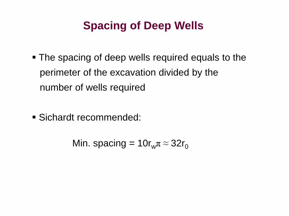
Spacing of Deep Wells
The spacing of deep wells required equals to the perimeter of the excavation divided by the number of wells required
Sichardt recommended:
Min. spacing = 10rwπ ≈ 32r0

Well Point Pump
Carson (1961)

Head vs. Discharge for Pump
Carson (1961)

Head vs. Discharge for Pump
Carson (1961)
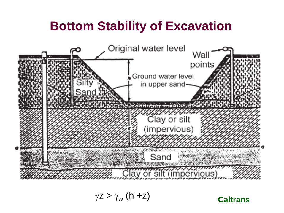
Bottom Stability of Excavation
γz > γw (h +z) Caltrans

Settlement of Adjacent Structures
'vo
'vo
c0
logCe1
Hσ
σ∆+σ+
=δ
whγ∆=σ∆
∆h = reduction of groundwater level

Examples

Plan View & Cross-Section
Xanthakos et al (1994)
Design Requirement
Lower the groundwater table to 5ft below the bottomof the excavation

Equivalent Radius and Influence Range
Equivalent radius of excavation
ft357ft500ft800r0 =π×
=
Height of water level in well
( ) ( )ft1130m340
107.43.0851403000khH'CR 5w
==×××−×=−= −
Influence range
h0 = 160 – 70 – 5 = 85 ft
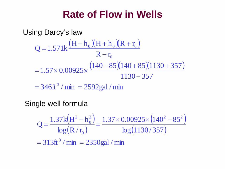
Rate of Flow in WellsUsing Darcy’s law
Single well formula
( )( )
( )( )
min/gal2350min/ft313
357/1130log8514000925.037.1
r/RloghHk37.1Q
3
22
0
20
2
==
−××=
−=
( )( )( )
( )( )( )
min/gal2592min/ft3463571130
3571130851408514000925.057.1
rRrRhHhHk571.1Q
3
0
000
==−
++−××=
−++−
=
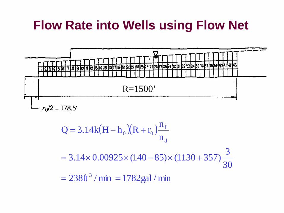
Flow Rate into Wells using Flow Net
( )( )
min/gal1782min/ft238303)3571130()85140(00925.014.3
nnrRhHk14.3Q
3
d
f00
==
+×−××=
+−=
R=1500’
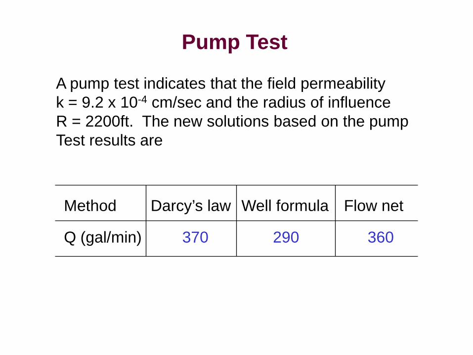
Pump Test
A pump test indicates that the field permeability k = 9.2 x 10⁻⁴ cm/sec and the radius of influenceR = 2200ft. The new solutions based on the pumpTest results are
Method Darcy’s law Well formula Flow net
Q (gal/min) 370 290 360

Xanthakos et al (1994)
Layout of Deep Wells
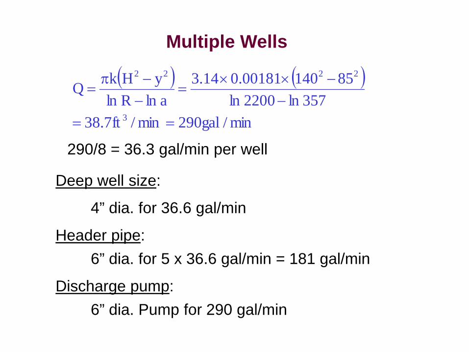
Multiple Wells
( ) ( )
min/gal290min/ft7.38357ln2200ln
8514000181.014.3alnRln
yHkQ
3
2222
==−
−××=
−−π
=
290/8 = 36.3 gal/min per well
Deep well size:
4” dia. for 36.6 gal/min
Discharge pump:6” dia. Pump for 290 gal/min
Header pipe:6” dia. for 5 x 36.6 gal/min = 181 gal/min


