DEWATERING IN THE HOT GROUNDWATER CONDITIONS AT LIHIR GOLD Stephanie Williamson, formerly Lihir Management Company, Senior Hydrogeologist: currently, Placer (Granny Smith) Pty Ltd, Senior Mine Hydrologist [email protected]Richard I. J. Vogwill, Senior Principal, URS Corporation, Perth, W Australia [email protected]ABSTRACT. Lihir Island is located in New Guinea, within a complex tectonic convergence zone between the Pacific and Indo-Australia Plates. The ore bodies occur in a collapsed volcanic crater in an active geothermal area adjacent to the sea. Open-pit mining at the Lihir Gold Mine commenced in mid-1997. The rock and groundwater temperatures range from 60 to 200°C. Dewatering is required for safe and efficient mining conditions and pit wall stability. The total drawdown required during the mine life is 200m, with over half of the drawdown required in the first 3 years. Dewatering is being achieved by pumping large diameter production bores using oilfield-type pumps; the total required pumping rate is about 1,000L/s. The pit dewatering system had significant problems in the first year of operation, which were exacerbated by an accelerated mine schedule. By late 1999, 90 to 110m of drawdown had been achieved in the pit area, and the drawdown cone was extending outwards into less permeable rock units. Keywords: open-pit, dewatering, hot groundwater INTRODUCTION The Lihir Gold Mine is located on Lihir Island in the New Ireland Province of Papua, New Guinea, about 900kms northeast of Port Moresby (Figure 1). The Ladolam orebodies (about 2km long, 1.5km wide and up to 200m deep) were discovered in 1982 and geological exploration continued throughout the 1980s. The open-pit mine is in an active geothermal area within a collapsed volcanic crater that has been breached on the eastern side by the ocean. The groundwater temperatures in the mine area are generally above 60 o C, creating a technically challenging mining environment. A Kennecott Explorations/Niuigini Mining Ltd Joint Venture (Kennecott et al., 1992) completed the final mining feasibility study in 1992. Construction commenced in 1996 and mining started in mid-1997. The current economic reserves are expected to last until 2014, followed by ore stockpile processing until 2031. Conventional drill and blast techniques are used with explosives that are designed for the elevated rock temperatures. The mine plan comprises deepening and expanding the pit outwards in phases, starting with the highest- grade ore in the Minifie orebody, and subsequently proceeding through the Lienetz orebody. Open-pit dewatering using vertical production (dewatering) bores is required during mining to maintain a safe and efficient working environment. This paper describes the hydrogeology of the Lihir Gold Mine, the dewatering infrastructure that has been installed, and the dewatering that has been achieved during the early years of mining. DEWATERING OVERVIEW The dewatering strategy resulting from the 1992 Feasibility Study (FS) was to reduce groundwater inflows to the open pit by pumping groundwater from vertical dewatering bores. The bores would be drilled into major aquifer zones on the seaward (north to northeast) side IMWA Symposium 2001
Transcript
DEWATERING IN THE HOT GROUNDWATER CONDITIONS AT LIHIR GOLD
Richard I. J. Vogwill, Senior Principal, URS Corporation, Perth, W Australia [email protected]
ABSTRACT. Lihir Island is located in New Guinea, within a complex tectonic convergence zone between the Pacific and Indo-Australia Plates. The ore bodies occur in a collapsed volcanic crater in an active geothermal area adjacent to the sea. Open-pit mining at the Lihir Gold Mine commenced in mid-1997. The rock and groundwater temperatures range from 60 to 200°C. Dewatering is required for safe and efficient mining conditions and pit wall stability. The total drawdown required during the mine life is 200m, with over half of the drawdown required in the first 3 years. Dewatering is being achieved by pumping large diameter production bores using oilfield-type pumps; the total required pumping rate is about 1,000L/s. The pit dewatering system had significant problems in the first year of operation, which were exacerbated by an accelerated mine schedule. By late 1999, 90 to 110m of drawdown had been achieved in the pit area, and the drawdown cone was extending outwards into less permeable rock units.
Keywords: open-pit, dewatering, hot groundwater
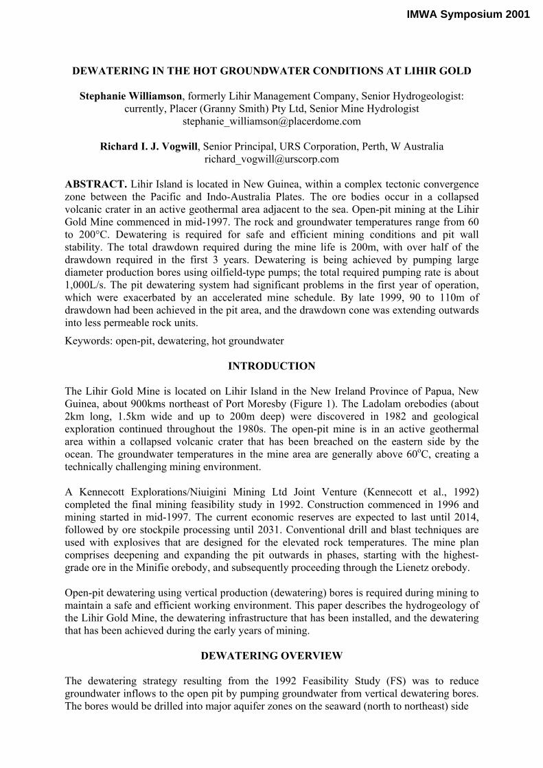
INTRODUCTION The Lihir Gold Mine is located on Lihir Island in the New Ireland Province of Papua, New Guinea, about 900kms northeast of Port Moresby (Figure 1). The Ladolam orebodies (about 2km long, 1.5km wide and up to 200m deep) were discovered in 1982 and geological exploration continued throughout the 1980s. The open-pit mine is in an active geothermal area within a collapsed volcanic crater that has been breached on the eastern side by the ocean. The groundwater temperatures in the mine area are generally above 60oC, creating a technically challenging mining environment. A Kennecott Explorations/Niuigini Mining Ltd Joint Venture (Kennecott et al., 1992) completed the final mining feasibility study in 1992. Construction commenced in 1996 and mining started in mid-1997. The current economic reserves are expected to last until 2014, followed by ore stockpile processing until 2031. Conventional drill and blast techniques are used with explosives that are designed for the elevated rock temperatures. The mine plan comprises deepening and expanding the pit outwards in phases, starting with the highest-grade ore in the Minifie orebody, and subsequently proceeding through the Lienetz orebody. Open-pit dewatering using vertical production (dewatering) bores is required during mining to maintain a safe and efficient working environment. This paper describes the hydrogeology of the Lihir Gold Mine, the dewatering infrastructure that has been installed, and the dewatering that has been achieved during the early years of mining.
DEWATERING OVERVIEW The dewatering strategy resulting from the 1992 Feasibility Study (FS) was to reduce groundwater inflows to the open pit by pumping groundwater from vertical dewatering bores. The bores would be drilled into major aquifer zones on the seaward (north to northeast) side
IMWA Symposium 2001
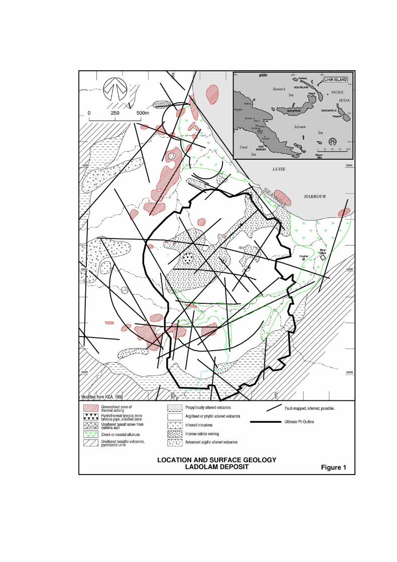
of the ultimate pit (the “Interceptor Wellfield” area – Figures 2 and 3). The resulting cone of depression was predicted to extend along permeable structural features to give sufficient drawdown on the western and southern sides of the open-pit. The pumped groundwater would be discharged to the sea via a surface drainage system and Ladolam Creek. A “seawall” (Figure 1) between the ultimate pit perimeter and Luise Harbour was planned to behave as a barrier to water recharge from the seaward side of the mine area. Much of the long-term dewatering strategy will focus on minimising inflows through the seawall area. The pumping rates (1,000 to 1,200L/s for the first two years of mining) needed to meet the mine schedule were determined from a combination of groundwater flow and geothermal modelling during the FS (Kennecott et al., 1992; Forth, 1994). These pumping rates were predicted to result in groundwater levels that would generally be 10m below the lowest mining benches at all times. Dewatering bores up to 300m deep were planned to meet the life-of-mine dewatering requirements. Local areas of perched groundwater behind the pit walls were to be depressurised via horizontal drain holes. A groundwater monitoring bore network across the mine area was planned to measure the dewatering progress behind the pit walls and below the pit floor. The dewatering strategy included geothermal mitigation measures, to reduce the risk of geothermal eruptions or blowouts. This aspect of the strategy commenced during 1999 with the drilling of eight deep directional geothermal wells, although this will not be discussed in this paper.
Due to the expected groundwater temperatures and corrosive environment, special oilfield/geothermal-type electro-submersible pumps (ESPs) and corrosion-resistant dewatering and monitoring borehole materials were necessary. In late 1997, the unexpected failure of the first four dewatering bores (in the Interceptor Wellfield area) required a new bore design and dewatering schedule. The mine schedule had been accelerated and to keep the dewatering ahead of the mining, the location of the dewatering bores was revised. The new borefield was installed along a corridor (Figure 3), rather than in one specific area (the Interceptor Wellfield) as originally proposed, and closer to the pit. Some bores had to be located inside the pit and, on occasion, these would have to be decommissioned for several months and then re-equipped while mining proceeded. Only minor changes to the mine design were required to allow access to the bore collars. In early 2000, it became apparent that the initial dewatering and geothermal mitigation requirements would be less than those predicted in the FS.
GEOLOGICAL SETTING The Lihir Group of islands is located within a complex tectonic convergence zone between the Pacific and Indo-Australia Plates on the western side of the Pacific Rim. Geothermal activity and epithermal gold mineralisation occur on Lihir Island. The island is estimated to be 0.2 to 3.7 million years old (Pliocene to Recent age) and comprises five volcanic landforms. One of these, the caldera of the Luise Volcano, is the most prominent topographic feature (600m above sea level) on the island and hosts the Ladolam ore bodies. The caldera is believed to have formed following an explosive unroofing of the Luise Volcano and subsequent sector collapse along the northeastern flank, leading to breaching by the ocean to form Luise Harbour.
The orebodies are hosted by volcanic breccias and intrusives that are underlain by volcanic basement rocks (Figure 1). The host rocks have been significant altered so classification is by ore type rather than rock type. There are two main areas of sulfide mineralisation: Minifie to the south (which outcrops at the surface) and Lienetz to the north. The host rocks have been subjected to two distinct episodes of alteration: an early porphyry-style deep alteration, related to the pre-collapse volcano and a later, shallower epithermal alteration, which commenced as a result of the unroofing and sector collapse. The porphyry-style alteration generally occurs at depths greater than 100m below sea level. Late stage epithermal alteration overlies and overprints the porphyry-style alteration and hosts the gold mineralisation. From a hydrogeological aspect, the three most important ore types are:
• the siliceous breccia (SBX), which has an open, vuggy, crumbly and fractured texture formed through leaching and intense hydrothermal brecciation of the parent rock;
• the boiling zone (BZ), which is characterised by a pin-point porosity texture, open cavities and breccia and formed by depressurisation and unloading of overlying rocks, which caused fluids to boil; and
• sealed zones (S), which occur at depths of 250 to 400m in the Minifie-Lienetz areas and are generally thought to form a reasonably effective aquitard under large areas of the caldera. These zones comprise altered rocks with pervasive veins and patches of various minerals (anhydrite, carbonate or quartz) which infill vugs, fractures, and joints. In particular, the anhydrite-sealed (AHS) zone is thought to have a very low permeability due to its dense character and origins as a caprock.
The major geological structures in the caldera comprise a series of northwest-trending transform faults and attendant secondary faults. These structural features are probably related to both volcanic emplacement and caldera collapse. Major sub-vertical structures have a strong control on high-grade ore. Steeply-dipping ring structure faults and fractures occur along portions of the inside perimeter of the caldera walls. These structures represent the surface expression of arcuate sector collapse/slump planes. Figure 1 shows the major geological structures determined at the time of the FS; Figure 3 shows an updated interpretation of the structures within the caldera.
HYDROGEOLOGY The conceptual hydrological model of the Ladolam Deposit is shown on Figure 2 and the occurrence of aquifers in the caldera is shown in Figure 3. Groundwater Geology Groundwater occurrence and flow are largely controlled by two types of permeability development that form prospective groundwater drilling targets for dewatering bores (Figure 3):
• secondary permeability features such as sub-vertical major structures (fault zones, shear zones and fractures); and
• “primary” permeability rock textures such as pin-point porosity, vugs, cavities and open breccias; the BZ and SBX are good examples.
Most of the other ore and rock types in the mine area have very low primary permeability.
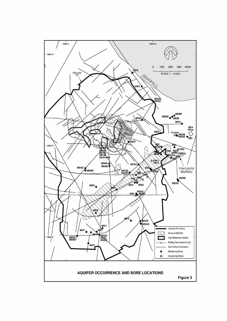
The conceptual hydrogeology of the deposit (Dames & Moore, 1998) comprises a dual-aquifer system – sub-vertical structures and permeable rock textures (Figure 3). The occurrence of aquifer zones is structurally controlled and the resulting permeability of the rocks is therefore strongly anisotropic. The sub-vertical structures are responsible for the development of the SBX/BZ aquifer zones and the graben-like structure under the lower reaches of Ladolam Creek (Figures 3 and 4). The major structures are thought to hydraulically connect adjacent areas of the deposits and to form permeable links between sub-horizontal aquifer zones. Long term pumping and injection tests during the FS and the initial dewatering results confirm that the structures are significant permeable features related to the formation of the SBX/BZ aquifer zones. The SBX/BZ zones (Figure 3) are highly permeable, confined aquifers and, based on thermal discharge areas in Luise Harbour, extend offshore. The ring structures (Figures 1 and 3) are generally of moderate permeability. Outside the ring structures (i.e. outside the caldera), the rocks generally have a lower permeability. Below the top of the sealed zone, many (but not all) sub-vertical structures have a low permeability and this is thought to be the lower boundary of the most active groundwater flow system. A large groundwater salinity gradient occurs across the boundary. Locally, some permeable structures extend at depth below the sealed zones, and these are the main targets for the geothermal mitigation measures (not discussed in this paper). The SBX/BZ frequently occurs in troughs (which coincide with structures) at the top of sealed zones.
Aquifer Parameters and Modelling As a result of nine injection/pumping tests (usually with numerous observation bores) completed between 1988 and 1991 and early dewatering results (Table 1), the aquifer parameters of some of the rocks comprising the Ladolam deposit are known on a local scale. During all tests, an anisotropic aquifer response was observed, with groundwater level changes occurring mainly along permeable structures in the rock, indicating that most aquifers within the deposit result from the fractured rock environment. The permeability of the rocks tested is generally high and confirms the potentially large dewatering requirements. Due to operational constraints, constant-rate aquifer tests are generally not completed in new dewatering bores; however, additional aquifer parameters have been derived from distance-drawdown analysis of early dewatering results (Dames & Moore, 1998). The resulting values of permeability (2 to 12 m/day) agree well with previously calculated values (Table 1). Step-rate discharge tests could not be completed in the first dewatering bores because the pressure transducers installed on the initial ESPs did not give an accurate response during the first 6 hours of pumping. Based on the aquifer parameters derived from the 1988 to 1991 testing, a multi-layer, three dimensional groundwater flow model of the deposit was constructed by discretising the deposit into blocks of differing aquifer parameters (Kennecott et al., 1992; Forth, 1994). The model included density and viscosity coupling to allow the geothermal heat effects on groundwater flow to be simulated. The model was constructed by converting the fractured rock mass to a porous medium equivalent and assigning averaged permeabilities to the various material types modelled. The model was used to predict the dewatering requirements associated with mining for the life of the project. The groundwater model was run in conjunction with a geothermal model, with temperature boundary conditions shared by the two models.
Table 1. Summary of Derived Aquifer Parameters
Well Area Test
Time (days)
Flow (L/s)
T (m2/day)
S (-)
K (m/day)
*
Aquifer Zone
DCM-1 M 19.8 31 3000 0.002 to 0.08
10 to 40 Breccia
DCM-2 M 12 33 3000 0.0005 10 to 40 Breccia DCM-3a L 23.5 30 400 to 800 0.005
to 0.01 40 BZ
DCM-3b L 9.9 35 1800 to 2700 0.0004 40 BZ G1 L 17.0 36 550 to 3600 0.0005 0.01 to
10 AHS
G4 M 3.0 22 2000 0.01 0.01 to 10
AHS
L212 C 4.0 2.0
29 30
550 0.0008 0.01 to 10
AHS
PB-1 La 10.0 42 2500 to 3500 0.0001 to
0.005
10 to 40 Breccia
L312 M/L 0.08 1.4 800 - 8 Various Low K
area PW1 to 4 La 8 326 500 to 700 0.01 to
0.3 2 to 7 Structure
and breccia
PW1 to 4 La 32 260 700 to 1200 0.03 to 0.3
2 to 12 Structure and
breccia Notes: *Flow modelling values; M=Minifie; L=Lienetz; La=Ladolam Creek; C=Coastal; T=transmissivity; S= storativity; K=permeability. Groundwater Movement, Temperature and Recharge/Discharge The initial groundwater levels in the Minifie and Lienetz areas (Figure 4) were within 10 to 20m of the pre-mining ground surface; at the coast, groundwater levels were at the surface. Groundwater flow was generally towards Ladolam Creek and then towards Luise Harbour (Figures 2 and 4). Due to the geothermal nature of the area, groundwater temperatures are high and locally supercritical in that they fall above the boiling point-pressure curve. The distribution of groundwater temperature was initially determined from temperature-depth surveys in exploration drillholes and monitoring bores. The highest temperatures are in the western and northwestern areas of the deposit (Figure 2) and these areas are termed geothermal upflow areas. ‘Tongues’ of hot water in the upper Ladolam Creek valley indicate deep permeable structures along which geothermal outflow occurs. Large outflow areas of hot geothermal fluids occur along the coast and in Luise Harbour; these are areas of significant groundwater discharge (Figure 3). The groundwater isotherms for 800mRL (200m below sea level) are shown on Figure 4.
Aquifers within the deposit are rapidly recharged by rainfall (Figure 2). Major permeable structures extend upwards into the near-surface ore types and, based on monitoring data and horizontal drainhole flows, are in good hydraulic connection with the overlying alluvium and drainage features. This results in rapid recharge to shallow aquifers behind pit walls during heavy rainfall. The permeable units and structures are capable of transmitting significant quantities of groundwater and recharging meteoric water (Figures 2 and 4), which has a cooling effect on the upper part of the reservoir. Such zones occur in Ladolam Creek valley, Lienetz and Kapit. Fortunately, the most prospective aquifers for the dewatering bores occur in the cooler parts of the deposit in the Ladolam Creek area. Groundwater Chemistry The groundwater chemistry is complex due to the geothermal nature of the area and proximity to the ocean. Based on the conceptual hydrological model of the deposit (Figure 2), geothermal fluids occur west and northwest of the deposit and underlie the deposit at depth. In specific higher-permeability areas, large rainfall recharge occurs and dilutes these geothermal fluids with cooler meteoric water. This results in lenses of 'fresher' groundwater floating on denser, more saline geothermal fluids. The deepest sampled geothermal fluids have:
• a neutral pH; • a Na-Cl-SO4 composition; • chloride concentrations approximately equal to seawater; • sulphate concentrations 5 to 15 times greater than seawater • a total dissolved solids (TDS) content up to 1.5 times that of seawater; • a density of up to 1.078kg/L; and • measured temperatures up to 230°C. Most components in these fluids indicate that they are distinct from seawater and from seawater altered in other geothermal systems. The total gas concentration is about 0.8 wt%, which reduces considerably in the cooler areas of the geothermal system. About 98% of the gases in the geothermal fluids are CO2 and H2S. East of the geothermal upflow areas and in areas with a high permeability, infiltrating meteoric water dilutes these fluids. Based on chemical analyses, the cooler 'mixed' groundwater is much less mineralised than the geothermal fluids. Groundwater sampled from the dewatering and monitoring bores has:
• a near-neutral pH; • a TDS content of about 20,000mg/L; • sodium and chloride values much less than seawater; and • a sulphate content almost double than of seawater. Analyses to date indicate that the groundwater being pumped from the Minifie Pit area was initially less mineralised than that from the Interceptor Wellfield - but is slightly hotter - and represents comparatively 'fresh' groundwater. As this fresh water was gradually removed by dewatering, the TDS content of the groundwater pumped by the Minifie dewatering bores increased from about 12,000mg/L in April 1998 to 25,000mg/L in June 1999. Groundwater from the horizontal drainholes is generally cool (less than 35°C), has a very small TDS (about 200mg/L) and low chloride concentrations (less than 20mg/L). This
groundwater originates from very recent rainfall recharge, which has infiltrated into major sub-vertical structures behind the pit walls.
DEWATERING INFRASTRUCTURE Bore Drilling and Construction The dewatering and monitoring bores were constructed using mud-rotary drilling methods in areas where the groundwater temperatures were below 100°C, so that the use of wellhead blow out prevention was not required. The horizontal drainholes were installed using a dual-drilling string assembly and down-the-hole air hammer in areas where the groundwater temperatures were below 60°C. From 1997 to 2000, four drilling programs (Figure 3) were completed:
• 1997 - four dewatering bores, average depth 285m (these bores failed after a few weeks of pumping); 23 monitoring bores up to 245 m deep.
• 1998 - six dewatering bores, average depth 260m; rehabilitation (casing replacement, gravel pack removal) of two failed bores to depths of 240m; 10 monitoring bores up to 221m deep; 50 horizontal drainholes;
• 1999 - rehabilitation of one failed bore to 207m and construction of one dewatering bore to 300m; 50 horizontal drainholes; and
• 1999/2000 - eight dewatering bores, average depth 275m; 28 monitoring bores up to 250m deep; over 100 horizontal drainholes.
All of the dewatering bores were drilled at 445mm diameter. The first four dewatering bores (Interceptor Wellfield) were completed using 330mm-diameter fibreglass-reinforced-plastic (FRP) casing with: centralisers; machined slots through the aquifer zones; and an annular gravel pack. The dewatering bores were developed by airlifting before pumps were installed. The selection of FRP casing was based on a 10-year design life and costs comparable to carbon steel. Carbon-steel casing was not used in these initial bores based on an estimated corrosion rate of 3mm per year. The use of more exotic alloys, with less predicted corrosion, was considered uneconomical. After the unexpected failure of the four dewatering bores in the Interceptor Wellfield area, the bore construction materials were modified to comprise L80 grade machine-slotted steel casing with centralisers but no annular gravel pack (to reduce potential point-source corrosion). This construction reduced the estimated bore life to three years, but was an acceptable risk based on: cost, the urgency to accelerate the dewatering and planned modifications to the dewatering system. A trial of Glass Reinforced Epoxy (GRE) casing was proposed for the last two dewatering bores drilled during 2000. During exploration, a network of groundwater and geothermal monitoring bores had been installed throughout the project area, however most of these were destroyed during development of the mine pit and surrounding infrastructure. Installation of a new groundwater monitoring bore network started in 1997 in areas where the groundwater temperatures were less than 100°C (Figures 3 and 4). Although this temperature range restricted bore locations, adequate coverage to monitor the early dewatering progress was achieved. Multi-level completions (up to 3 standpipes) were used locally (from the seawall area to the southern pit limits) to measure groundwater heads at different depths. Completions comprised short-screened intervals, annular gravel packs and impermeable seals. Casing selection varied depending on temperatures and depths. Generally, uPVC was used at
less than 100m for in-pit monitoring bores (the use of metal casing in the pit had the potential to damage conveyors and the crusher). Galvanized iron was used for deeper out-of-pit completions. An aromatic amine (suitable for 150°C) was used for in-pit completions greater than 100m. Monitoring bores were developed by airlifting and bailing. The geotechnical objective of the horizontal drainholes was to provide local depressurisation up to 60m behind final pit walls. Drainholes targeted known perched aquifers and cavities, and achieved advanced drainage of the interim pit walls. Drainhole locations were restricted to the upper benches of the southern and eastern pit areas where groundwater temperatures were less than 60°C and there were no gas discharges. The drainholes were up to 200m long, completed with slotted uPVC casing, and had flow rates of up to 5L/s. Equipping of Dewatering Bores Oilfield-type, variable-speed-drive ESPs, with up to 535kW oil-cooled motors, were installed in the dewatering bores. The materials selected for pumps, motors, seals, rising main, power cable and down-the-hole pressure and temperature monitoring instrumentation was designed to provide the most cost-effective life in the corrosive, hot, gassy groundwater conditions. The design criteria and acceptable service life for the pumps, motors and drives were revised downwards (reduced pumping rate and lift; 5 years to 3 years) after reviewing the early pumping results in the Interceptor Wellfield. This resulted in: (i) a larger selection of suitable equipment for the estimated range of bore yields and dynamic heads; and (ii) decreased capital and operating costs. The priority for the dewatering program is to maximise pumping rates and minimise the power usage. This was achieved by selecting variable-speed drives for the ESPs and thus only using the power required to maintain the selected flow rate. The power requirements were further reduced by optimising the variable-speed drive size (for new ESP units), based on the initial pumping water level and flow rate data. The initial equipment availability, excluding the dewatering bore failures, has generally been from 80 to 95%.
DEWATERING ACHIEVED The dewatering and pumping achieved during the first 2.5 years of mining and the planned mining schedule (end 1998 design) are shown in Figure 5. The original dewatering schedule required pumping to commence about 3 months ahead of the mining, but this did not occur. The start of mining was brought forward ahead of initial plans by 6 months to mid-1997. Pumping commenced in September 1997, but only lasted for a month at the design flow rates due to the failure of the first four bores in the Interceptor Wellfield. The pumping re-started in February 1998, effectively 12 months behind the schedule outlined in the FS.
Consequently, the mining conditions in early 1998 in the bottom of the Minifie Phase 1 pit were extremely difficult. As the groundwater level was generally at or above the pit floor, groundwater at 90 to 100°C was regularly encountered during mining.
Geyser-type activity was common and locally boiling muddy conditions made drilling, sampling and blasting difficult. Rock temperatures above 100oC were often encountered. Conditions were exacerbated by abandoned exploration drillholes (hydraulically connected to deeper, higher-head aquifer zones) which were intersected by mining. These holes discharged a hot water-steam-gas mixture and formed geysers in some areas of the pit. As dewatering
progressed however, all of the pit floor discharges and most of the exploration hole discharges ceased because the high groundwater heads in deeper aquifers were reduced. The total pumping rates from the dewatering bores gradually increased from 400L/s in late 1997 to 800L/s in April 1999 (Figure 5). The pumping rates from individual dewatering bores ranged from 50 to 130L/s; typical pumping water levels were 100 to 150m deep. The highest-yielding bores in the Ladolam Creek valley were those that intersected the maximum thickness of the SBX/BZ aquifer and major sub-vertical geological structures at more than 150m depth (Figure 3). The pumping rates decreased after September 1999 due to significant downtime on six pumping units (related to the replacement of pressure and temperature monitoring devices). Bores that could not sustain higher pumping rates have been progressively decommissioned as the dewatering schedule advances ahead of the mining schedule and have been replaced by higher-yielding bores completed in early 2000. After mid-1998, the groundwater levels could generally be held 10 to 20m below the lowest mining bench; however, the groundwater recovered rapidly (typically 10m in one day) if a dewatering bore stopped pumping. The drawdown and recovery in the aquifer zones due to changes in the pumping rate are clearly illustrated in the piezometer hydrographs (Figure 5). As the total pumping rate increased, an elongated drawdown trough developed along the major permeable structures and zones of SBX/BZ (Figure 4) under the Ladolam Creek valley and into the southern and western pit areas. The bounded setting of aquifers in this area resulted in strip-aquifer and boundary effects at the edges of the SBX/BZ zones and this increased the rate of drawdown achieved. The deepest part of the drawdown trough was very narrow across strike and very steep hydraulic gradients developed. With continued pumping, it became apparent that drawdown was also occurring along other major cross-cutting structural features, resulting in partial dewatering of other areas of the deposit. This inter-connected response of the aquifer systems was expected; however, the large drawdown achieved suggests that the long-term dewatering requirements may be less than predicted.
VALIDATION OF GROUNDWATER FLOW MODEL The original groundwater flow modelling that was completed for the FS was reviewed, updated and modified to include the new bore locations, to determine if it could be used for further predictive dewatering simulations (Dames & Moore, 1999). A number of transient scenarios were run using initial dewatering data (pumping rates and groundwater levels). The model predicted the same shape of drawdown as observed in the main SBX and BZ aquifer zones, but the magnitude of the observed drawdown was more than that predicted. The groundwater flow model predicted more drawdown than was observed in the southern parts of the mine area and less drawdown than was observed in the Lienetz areas. While these results suggest that the overall magnitude of dewatering may be less than predicted, they also imply that the current model may require “geological” modifications (i.e. the distribution of major permeable structural features) to be a useful predictive tool.
An attempt to recalibrate the model by modifying the hydraulic parameters did not produce a better match of observed vs. predicted drawdown. A substantial amount of new drilling data was available in 1999/2000 from major in-pit geological exploration programmes. Further groundwater modelling was put on hold until additional dewatering data were available and
the results of the new geological data could be incorporated into the conceptual hydrogeological model.
CONCLUSIONS The Lihir Gold Mine is located in a remnant volcanic crater that has been breached by the ocean. The open pit will be 200m below sea level and the northeastern wall of the open pit will be located next to the ocean. The mine is located in a geothermal area and this, combined with the remote and coastal location, has presented significant and unusual technical challenges for dewatering system installation and design. In the early stages of mining, the dewatering schedule was significantly behind the mining schedule and operating conditions were difficult because of the discharge of hot groundwater into the pit. With the start of pumping from high-yielding dewatering bores, however, mining conditions improved significantly and mining has proceeded on schedule and within an effectively dewatered pit environment Dewatering results to date have been favourable and about 100m of drawdown in the mine area has occurred. The bounded nature of the major aquifers in the mine area has resulted in larger drawdowns than predicted. Future dewatering investigations will centre on determining the potential water inflows through the seawall and the modification of the existing groundwater flow model in order to predict future and ongoing dewatering requirements.
ACKNOWLEDGEMENTS The authors would like to thank the Lihir Management Company for permission to publish this paper and Steve Hunt for editing the manuscript. Special thanks are due to the local Lihirian and PNG National dewatering staff (geologist, electrician and technicians) who were completing their first hydrogeological and dewatering project. The significant problems encountered during the initial stage of the dewatering was overcome by a team effort including mining, electrical and geology personnel, assisted by several contractors (consultants, drilling, electrical and pump suppliers).
BIBLIOGRAPHY Dames & Moore Pty Ltd. (1998) Hydrogeology and Dewatering Review, Lihir Gold Mine, Lihir Island, PNG. Unpublished Report to Lihir Management Company. Dames & Moore Pty Ltd. (1999) Ground Water Modelling for Dewatering Design, Lihir Gold Mine. Unpublished Report to Lihir Management Company Forth, J. (1994) Dewatering and Geothermal Control for the Proposed Lihir Mine, Papua New Guinea, The Australasian Institute of Mining and Metallurgy, Proceedings of the PNG Geology, Exploration and Mining Conference, Lae. Rogerson, R. (Ed.), pp 212-218. Kennecott Explorations (Australia) Ltd and Niuigini Mining Ltd Joint Venture. (1992) Volume 4, Lihir Project Feasibility Study, Mine Dewatering and Geothermal Control.