28
Pinakin Patel Mohammad Farooque FuelCell Energy, Inc. 3 Great Pasture Road Danbury, Ct 06813 DFC Technology Status
| Date post: | 08-Nov-2018 |
| Category: |
Documents |
| Upload: | truongthuan |
| View: | 221 times |
| Download: | 0 times |

Pinakin PatelMohammad Farooque
FuelCell Energy, Inc.3 Great Pasture RoadDanbury, Ct 06813
DFC Technology Status

• Distributed generation puts power where it’s needed
• Increases power reliability
• Near zero emissions allow units to be sited almost anywhere – even polluted urban areas
• Reduces need for central generation plants
• Reduces grid congestion and need for new transmission lines
• Distributed generation enables smart grid
• Balances the grid with 24/7 power
• Meets requirements for low carbon technology
• Smaller projects enable faster permitting, financing, and execution
DFC power plant is an enabler for broad distributed generation
600 kW at M&L Commodities
Distributed Generation
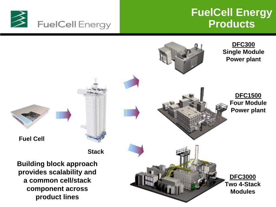
FuelCell Energy Products
Fuel Cell
Stack
DFC300Single Module Power plant
DFC3000Two 4-Stack
Modules
DFC1500 Four Module Power plant
Building block approach provides scalability and
a common cell/stack component across
product lines

Grid Support, RPS 10 MW +
1.4 MW300 kW
Average-Sized Grocery Stores, 300-Bed Hotels
300-Bed Hospitals, Manufacturing, Universities
1000-Bed Hotels, Convention Centers, Wastewater Treatment, Food/Beverage
2.8 MW
MO3258
DFC Typical Applications

DFC power plants offer the highest efficiency of any distributed generation technology
High Electrical Efficiency
Fuel
to E
lect
rical
Effi
cien
cy 60%
40%
20%
30%
50%
10%Micro-
turbines 25 – 30%
Small Gas Turbines 25 –35%
Natural Gas Engines 30 – 42%
DFC-ERG DFC/Turbine
58 – 65%
Direct FuelCell (DFC)
47%
MO3262

CO2
(lb/MWh)
NOX
(lb/MWh)
SOX
(lb/MWh)
PM10
(lb/MWh)Average US Fossil Fuel Plant 2031 5.06 11.6 0.27
Average US Generation 1408 3.4 7.9 0.19
Typical Small Gas Turbine 1494 1.1 0.008 0.08
DFC (Baseline products) 980 0.01 0.0001 0.00002
DFC Potential (at 65% Efficiency) 680 0.007 0.00007 0.00001
Direct Fuel Cell Emissions Compared to Others

Source for non-DFC data: PAFC data from product brochure; Other data from “Model Regulations For The Output Of Specified Air Emissions From Smallerscale Electric Generation Resources Model Rule and Supporting Documentation”, October 15, 2002; The Regulatory Assistance Project report to NREL
DFC: Cleanest Power at the Highest Efficiency
Cle
aner
Pow
erC
lean
er P
ower
Higher Efficiency and Lower COHigher Efficiency and Lower CO22
0.0
0.1
1.0
10.0
100.0
1000.0
25% 30% 35% 40% 45% 50% 55% 60%Electrical Efficiency
MW
hpe
r lb
Emis
sion
s (N
OX
+ SO
X+
PM10
)
DFC/T
Direct FuelCell
Large Combined
Cycle
PAFC
Average US Fossil Gen
Lean burn EngineSmall
Turbine
Engine w Catalyst
Micro-turbine
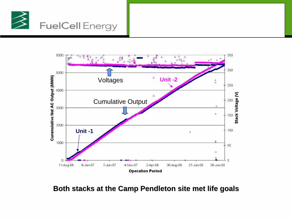
Voltage and Net Power Production Trends in DFC300MA
Units at Camp Pendleton
Voltages
Cumulative Output
Unit -1
Unit -2
Both stacks at the Camp Pendleton site met life goalsBoth stacks at the Camp Pendleton site met life goals

Typical Operating Point of a 2.4 MW Power Plant
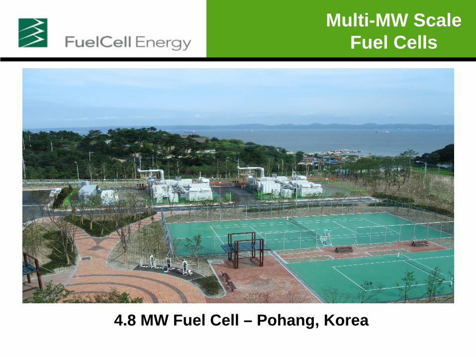
4.8 MW Fuel Cell – Pohang, Korea
Multi-MW Scale Fuel Cells

• More power for given amount of biogas: Higher efficiency than any other generation at typical digester facility sizes
• Good heat to power ratio for digester support: Fuel cell makes enough heat to support digester operation
• Avoids generation of NOX and other pollutants from flare or from other generation technologies
DFC Edge in Biogas Applications

King County Seattle
1 MW Municipal Wastewater Treatment Plant First Site with Online Fuel Switching

Kirin Brewery Project
First SubMW Digester Gas Project, Running on Biogas from Beer Production
Kirin Brewery Project
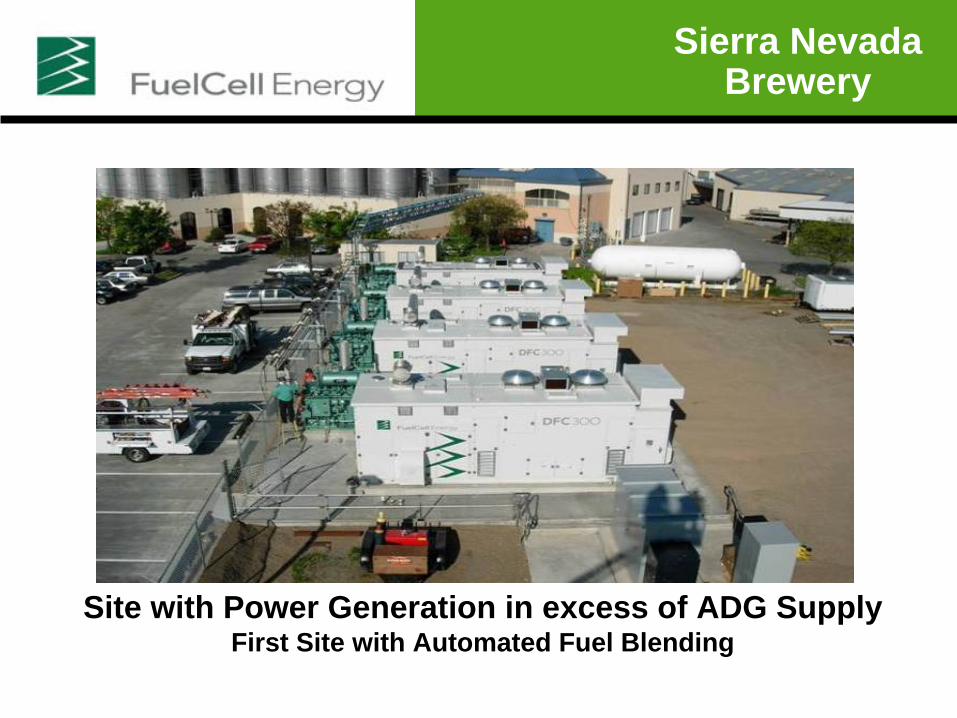
Sierra Nevada Brewery
Site with Power Generation in excess of ADG Supply First Site with Automated Fuel Blending

MW and Sub-MW DFC® Worldwide Installations
Markets• 95 MW installed/backlog
– Japan/Korea: 72 MW – California/West Coast: 15 MW
– Northeast/Canada: 5 MW– Europe: 2 MW
• Targeted applications– Grid Support: 69 MW– Renewable/Wastewater: 9 MW– Manufacturing: 7 MW – Hotels: 3 MW – University & Hospitals: 2 MW
– Government: 3 MW– DFC-ERG: 2 MW
MO3259
Current Market

• Production and delivery capabilities meet current demand
• State-of-the-art manufacturing in Torrington, CT
• 70 MW capacity
• Production rate of 30 MW/year
• Strong supply chain in place
• Expansion plan to achieve 150 MW capacity
DFC Production
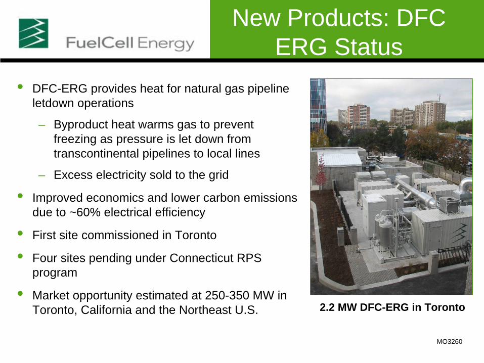
• DFC-ERG provides heat for natural gas pipeline letdown operations
– Byproduct heat warms gas to prevent freezing as pressure is let down from transcontinental pipelines to local lines
– Excess electricity sold to the grid
• Improved economics and lower carbon emissions due to ~60% electrical efficiency
• First site commissioned in Toronto
• Four sites pending under Connecticut RPS program
• Market opportunity estimated at 250-350 MW in Toronto, California and the Northeast U.S. 2.2 MW DFC-ERG in Toronto
MO3260
New Products: DFC ERG Status

Products Under Development: DFC/T Fuel Cell Turbine Hybrid
System
• Fuel cell waste heat drives unfired turbine
• Electrical efficiency increased from 47% to 58- 60%
• Field tested in DFC300 based subMW system
• Commercial product being designed based on DFC3000, 3.4 MW rating
–First unit approved under CT Project 100
Billings, MT field test

Products Under Development: Electricity and Hydrogen Co-
production
H2 Purification
A/E Cooing
E-BOP
M-BOP
DFC300
H2 Purification
A/E Cooing
E-BOP
M-BOP
DFC300
kWs to electric load
H2 to refueling station or industrial user
Heat to buildingsthermal load

Products Under Development: Electricity Co-production and
Carbon Separation
• Exhaust from fossil fuel plant used as DFC oxidant
• CO2 from fossil fuel plant transferred and concentrated for efficient sequestration
• Produces additional power, unlike other carbon capture concepts
MO3237
Power Plantor
ProcessEmitting CO 2
Greenhouse Gas
CO2Separator
CATHODE
ANODE
CO2Capture(~90% CO2)
Water
CO2 - DepletedFlue Gas(~1% CO2)
Flue Gas(~10% CO2)
Hydrogen - Rich Fuel
Recycle or
Sell
SupplementalFuel
FossilFuel
Air
POWER
DirectFuelCell
(DFC)
POWER

DFC System Performance Summary Projection
DFC system has shown excellent performance in separation of carbon dioxide, in the study of various types of coal fueled power plants
> 90% CO2 separation from the greenhouse gas
(per unit energy produced)
DFC provides additional power
* Preliminary results prior to input from fuel cell test results
PLANT TYPE
w/o DFC with DFC w/o DFC with DFC
Pulverized Coal (PC) Steam Plant 200 341 1838 108ACFB Steam Plant 200 353 1997 113IGCC Plant 200 327 1657 101
lbs/MWhr
Net Power CO2 MW to Environment

Pohang, Korea
• 300 kW, 1.4 MW, and 2.8 MW size products for CHP applications
• Product performance expanding markets
• Customers/applications providing repeatable order flow – Asia, California, Connecticut
• RPS and South Korean markets creating multi-MW volume (84% of the installed and backlog volume in Asia) .
• Established manufacturing capability to meet current and future demand
• Cost reduction and volume on path to profitability
MO3261
DFC Status Summary


Direct FuelCell Attributes
Higher electrical efficiency than competing technologies (approaching 50% in simple cycle distributed generation applications)
Fuel flexible (NG, biogas, propane, coal-bed methane, and methanol)
Modular
• Easily siteable at load centers (simple connections to grid and fuel infrastructure)
• Near-zero NOX , SOX and low CO2 emissions as well as quiet operation
• Reliable, 24/7 power
• High grade waste heat for combined heat & power (CHP; overall efficiency can achieve 90%)
Competitive advantage on renewable biogas over other technologies
Enabler for transformational technologies
• High efficiency (58-65%) combined cycle systems in small size range (DFC/T)
• Co-production of electricity and hydrogen (DFC-H2 )
• Co-production of electricity from coal and CO2 separation
• High efficiency energy (>60%) recovery generation ( DFC-ERG) system

Current DFC Products
Cell Package and Stack
Single-Stack Module
Four-Stack Module
DFC300 Single Module Power Plant
DFC3000: Two 4- Stack Modules
DFC1500A Four Module Power Plant
DFC1500B One 4-Stack
Module

0
10
20
30
40
50
60
70
0.1 1 10 100 1000System Size, MW
Effic
ienc
y, %
(LH
V)
Direct FuelCell ® Combined Cycle
Gas TurbineLow Temp FC
Coal/Steam
Micro-
Turbine
Engines
DFC/T Hybrid
DFC2/T Hybrid
Average U.S. Fossil Fuel Plant = 33%
MO3236
Direct Fuel Cell Efficiency Comparison with Competition

• Production and delivery capabilities meet current demand
• State-of-the-art manufacturing in Torrington, CT
• 70 MW/yr capacity– Current production rate 30 MW/year
• Strong supply chain in place
• Expansion plan to achieve 150 MW capacity Torrington, CT
Danbury, CT
DFC Production Readiness


