65
DG 415-2 01 JUNE 2011

DG 415-2 01 JUNE 2011

DG 415-2 01 JUNE 2011
i
FOREWORD
This Logistics Facilities Design Guide (DG 415-2) was published by the National Guard Bureau, Army Installations Division (ARNG-ILI). This DG applies to all projects for new construction (including additions) as well as alterations to and rehabilitation and conversion of existing facilities. It is intended to assist the States, Territories, the District of Columbia and design professionals in gaining an understanding of the functions and the unique environmental considerations to address in the construction documents development. This design guide does not contain criteria but refers readers to sources of criteria in other publications that relate directly to specific technical design requirements. This Logistics Facilities Design Guide should be used in conjunction with the General Facilities Information Design Guide (DG 415-5) to develop the final project design. Distribution is limited. However, authorized users of the NGB Guard Knowledge Online (GKO), can obtain an electronic copy at (gkoportal.ngb.army.mil/sites/ARI_HQ/default.aspx), Design, Guide Library site. All users are encouraged to submit comments and suggestions to improve this document by completing DA Form 2028, “Recommended Changes to Publications and Blank Forms,” and sending it directly to:
National Guard Bureau Installations Division
ARNG Readiness Center 111 South George Mason Drive
Arlington, VA 22204-1382

DG 415-2 01 JUNE 2011
ii
CONTENTS
Page
Chapter 1 General Information ................................................................................... 1
1-1 Purpose: Performance Design Guide ....................................................... 1 1-2 Functions And Operations Of Logistics Facilities ....................................... 1
Chapter 2 United States Property And Fiscal Office ................................................... 2
2-1 General Information ................................................................................... 2 2-2 USPFO Administrative and Office Facility .................................................. 2 2-2.1 General Information ................................................................................... 2 2-2.2 Functional Areas ........................................................................................ 3 2-2.2.1 Automated Data Processing Area .............................................................. 3 2-2.2.2 Telecommunications Center ...................................................................... 3 2-3 USPFO Warehouse Facility ....................................................................... 3 2-3.1 General Information ................................................................................... 3 2-3.2 Functional Areas ........................................................................................ 3 2-3.2.1 Functions and Operations .......................................................................... 3 2-3.2.2 Special Design Requirements .................................................................... 4 2-3.3 Exterior Design Elements .......................................................................... 4 2-3.3.1 Flammable Materials Storage .................................................................... 4 2-3.3.2 Mail Room .................................................................................................. 4 2-3.3.3 Controlled Waste Handling Facility ............................................................ 4 2-3.3.4 Loading Dock ............................................................................................. 4 2-3.3.5 Service Apron ............................................................................................ 5
Chapter 3 Surface Equipment Maintenance Facility ................................................... 6
3-1 General Information ................................................................................... 6 3-2 Field Maintenance Shop (FMS) ................................................................. 6 3-3 Maneuver Area Training Equipment Site (MATES) ................................... 6 3-3.1 Maneuver Area Training Equipment Site Without Sustainment
and Unit Training Equipment Site .............................................................. 6 3-3.2 Maneuver Area Training Equipment Site With Sustainment ...................... 7 3-4 Combined Support Maintenance Shop (CSMS) ........................................ 7 3-5 Common Supporting Items and/or Areas ................................................... 7 3-5.1 Cannibalization Areas ................................................................................ 7 3-5.2 Unheated Parts Storage ............................................................................ 7 3-5.2.1 General Design Considerations ................................................................. 7 3-5.2.2 Building Materials ...................................................................................... 8 3-5.3 Ventilation .................................................................................................. 8
DG 415-2 01 JUNE 2011
iii
3-5.4 Gas Sensors .............................................................................................. 8 3-5.5 Personnel Doors ........................................................................................ 8 3-5.6 Fire Alarm .................................................................................................. 8 3-5.7 Emergency Shower/Eyewash. Station (ES/EW) ........................................ 8 3-5.8 Fuel Storage And Dispensing System ....................................................... 9 3-5.8.1 Storage Tanks ........................................................................................... 9 3-5.8.2 Fixed Fuel-Dispensing Facilities ................................................................ 9 3-5.8.3 Fueler Vehicle Parking Pads...................................................................... 9 3-5.8.4 Dispensing Nozzles ................................................................................... 9 3-5.9 Loading Dock ............................................................................................. 9 3-5.10 Work Bay Service Island .......................................................................... 10 3-5.11 Military Vehicle Loading Ramp ................................................................ 11 3-5.12 Maintenance Bay Access Aprons ............................................................ 11 3-5.13 Wash Platform ......................................................................................... 11 3-5.13.1 Exterior Wash Platform ............................................................................ 12 3-5.13.2 Optional Inside Washbay ......................................................................... 13 3-5.14 Waste Oil Storage Tanks ......................................................................... 13 3-5.15 Flammable Materials Storage Building .................................................... 13 3-5.16 Main Facility Building Design ................................................................... 13 3-5.16.1 Interior Finishes, Lighting, And Height Requirements .............................. 13 3-5.16.2 Installed Equipment ................................................................................. 13 3-5.16.3 Battery Room ........................................................................................... 13 3-6 Design Guidance for Program Spaces..................................................... 15 3-6.1 General Supervisor’s Office ..................................................................... 15 3-6.2 Supervisor’s Office ................................................................................... 15 3-6.3 Production Controller ............................................................................... 15 3-6.4 Inspector’s Administrative Work Area and Library ................................... 15 3-6.5 Administrative Assistant/Secretary .......................................................... 15 3-6.6 Common Information Technology Space ................................................. 15 3-6.7 Information Technology Support Activities ............................................... 16 3-6.8 Classroom ................................................................................................ 16 3-6.9 Latrine/Shower ......................................................................................... 16 3-6.10 Locker Room(s) ....................................................................................... 16 3-6.11 Break Area ............................................................................................... 16 3-6.12 Physical Fitness Area .............................................................................. 16 3-6.13 Tool Room ............................................................................................... 16 3-6.14 Supply Room ........................................................................................... 17
3-6.15 Communications and Electronic Shop ..................................................... 17 3-6.16 Instrument Repair Shop ........................................................................... 17 3-6.17 Small Arms Repair Shop .......................................................................... 17 3-6.18 Small Arms Test Room ............................................................................ 17 3-619 Vault (Small Arms) ................................................................................... 17 3-6.20 Vault (Combat Vehicle Arms) ................................................................... 17 3-6.21 Injector Test Room .................................................................................. 17 3-6.22 Fuel And Ignition Repair Shop ................................................................. 18 3-6.23 Basic Items of Issue Storage and Issue ................................................... 18 3-6.24 Machine Shop .......................................................................................... 18
DG 415-2 01 JUNE 2011
iv
3-6.25 Carpenter Shop ....................................................................................... 18 3-6.26 Lumber Storage Shed .............................................................................. 18 3-6.27 Canvas Shop ........................................................................................... 18 3-6.28 Missile Repair Shop ................................................................................. 18 3-6.29 Vault (Missile) .......................................................................................... 18 3-6.30 Calibration Room ..................................................................................... 19 3-6.31 Calibration Storage .................................................................................. 19 3-6.32 Glass Repair Room ................................................................................. 19 3-6.33 Radiator Test and Repair Room .............................................................. 19 3-6.34 Communication Security (COMSEC) Equipment Repair Room ............... 19 3-6.35 Radiation Calibration Room ..................................................................... 19 3-6.36 Bulk POL Storage for Lubrication System ................................................ 19 3-6.37 Bulk POL Storage .................................................................................... 20 3-6.38 Controlled Waste Handling Facility .......................................................... 20 3-6.39 Bulky Equipment Storage ........................................................................ 20 3-6.40 Flammable Materials Storage .................................................................. 20 3-6.41 Enclosed Unheated Storage .................................................................... 20 3-6.42 Workbay Dimensions ............................................................................... 20 3-6.43 General Purpose Workbays ..................................................................... 20 3-6.44 Warm-Up Bay .......................................................................................... 20 3-6.45 Welding Shop .......................................................................................... 21 3-6.46 Body Shop ................................................................................................ 21 3-6.47 Wash Bay ................................................................................................ 21 3-6.48 Paint Stripping Bay .................................................................................. 21 3-6.49 Paint Preparation Bay .............................................................................. 21 3-6.50 Paint Bay ................................................................................................. 21 3-6.51 Paint Kitchen ………………………………………………………… ......21 3-6.52 Engine/Transmission Test Cell ................................................................ 22 3-6.53 Armament Bay ........................................................................................ 22 3-6.54 Inspection Bay ......................................................................................... 22 3-6.55 Facility Maintenance and Custodial Area ................................................. 22 3-6.56 Mechanical, Electrical, and Telecommunications Room(s) ...................... 22
CHAPTER 4 Controlled Humidity Preservation (CHP) Shelters ................................... 23
4-1 General Information ................................................................................. 23 4-2 Design Considerations ............................................................................. 23 4-2.1 Civil Design .............................................................................................. 23 4-2.2 Architectural Design ................................................................................. 23 4-2.2.1 Aesthetics ................................................................................................ 23 4-2.2.2 Flexibility .................................................................................................. 23 4-2.2.3 Interior Height ................................................................................... … 24 4-2.2.3.1 Thermal and Moisture Protection ............................................................. 24 4-2.2.3.2 Floors … .................................................................................................. 24 4-2.2.3.3 Doors …. .................................................................................................. 24 4-2.2.4 Roof System ............................................................................................ 24 4-2.2.4.1 Gutters/Downspouts ................................................................................ 24 4-2.3 Pre-Engineered Metal Building ................................................................ 24

DG 415-2 01 JUNE 2011
v
4-2.3.1 General Design ........................................................................................ 24 4-2.3.2 Roof and Wall Panels .............................................................................. 25 4-2.4 Structural Design ..................................................................................... 25 4-2.4.1 General ................................................................................................... 25 4-2.4.2 Exterior Walls .......................................................................................... 25 4-2.4.3 Foundation .............................................................................................. 25 4-2.4.4 Seismic Design Consideration ................................................................. 25 4-2.5 Mechanical Design .................................................................................. 25 4-2.5.1 General… ................................................................................................ 25 4-2.5.2 Ventilation and Humidity Requirements. .................................................. 25 4-2.5.3 Equipment Support .................................................................................. 26 4-2.5.4 Fire Protection System............................................................................. 26 4-2.5.5 Equipment Room .................................................................................... 26 4-2.5.6 Plumbing System .................................................................................... 26 4-2.6 Electrical Design ..................................................................................... 26 4-2.6.1 General ................................................................................................... 26 4-2.6.2 Service/Distribution .................................................................................. 26 4-2.6.3 Hazardous Classification ......................................................................... 26 4-2.6.4 Lighting System ....................................................................................... 26 4-2.6.5 Emergency Egress Lighting ..................................................................... 27 4-2.6.6 Fire Alarm and Detection System ............................................................ 27 4-2.6.7 Combustible Gas Detection ..................................................................... 27 4-2.6.8 Lightning Protection System ................................................................... 27 4-2.6.9 Intrusion Detection System (IDS) ............................................................ 27 4-2.6.10 Carbon Monoxide Control ....................................................................... 27 Chapter 5 Firefinder Radar Building……………………………………………………..28 Chapter 6 Unique Architectural and Engineering Technical Requirements .............. 29
Chapter 7 Unique Submission Requirements ........................................................... 30
Chapter 8 Unique Design Review Directive Requirements ...................................... 31
Appendix A Unique References .................................................................................. 32 Appendix B Glossary ................................................................................................... 33 B-1 Acronyms And Abbreviations ................................................................... 33 B-2 Unique Specialized Terms ....................................................................... 35
Appendix C Tables ...................................................................................................... 36
Table 1 Not Used.. ................................................................................................ 36 Table 2 Not Used .................................................................................................. 36 Table 3 Not Used .................................................................................................. 36 Table 4. Architectural Interior Finishes .................................................................. 37 Table 5. Doors, Hardware, Storage, and Shelving................................................. 41 Table 6. Mechanical Requirements – Part 1 .......................................................... 46
DG 415-2 01 JUNE 2011
vi
Table 7. Mechanical Requirements – Part 2 .......................................................... 50 Table 8. Electrical Requirements ........................................................................... 53 Table 9. Special Equipments and Ceiling Heights ................................................. 56
Appendix D Figures ..................................................................................................... 58 Figure 1 Figure 2 Figure 3

DG 415-2 01 JUNE 2011
1
CHAPTER 1.
GENERAL INFORMATION
1-1 PURPOSE: PERFORMANCE DESIGN GUIDE This Logistics Facilities Design Guide sets forth general functional guidance for the design architect-engineer (A-E) to use in developing the design and the construction documents for Army National Guard (ARNG) projects that qualify for support, totally or in part, from federal funds. This guide is applicable to all construction projects, including new construction, major alterations, rehabilitation and adaptive reuse of existing facilities. All ARNG facilities must be designed and constructed applying the principles and practices of sustainable design and development using the latest version of the U.S. Green Building Council Leadership in Environmental and Energy Design (LEED) Green Building Rating System to achieve a “Silver” rating.
This Design Guide addresses the unique functional design requirements for specific types of logistics facilities. It should be used in conjunction with the General Facilities Information Design Guide (DG 415-5), which contains basic design guidance common to all Army National Guard building types. Together, the two design guides provide the functional performance information necessary to assist in developing the facility design.
To aid the reader in using this design guide, the following are included:
▪ Appendix A, Unique References, lists reference documents that pertain specifically to this building type; other references cited in this design guide are included in the References in DG 415-5.
▪ Appendix B, Glossary, defines the acronyms and abbreviations used in this design guide as well as specialized terms.
▪ Appendix C contains several requirements tables.
1-2 FUNCTIONS AND OPERATIONS OF LOGISTICS FACILITIES This design guide pertains to the following types of ARNG logistic facilities.
▪ United States Property and Fiscal Office (USPFO)
▪ Surface Equipment Maintenance Facilities (SEMF)
▪ Unheated Enclosed Storage and Vehicle Storage
▪ Controlled Humidity Preservation (CHP) Program Facilities
DG 415-2 01 JUNE 2011
2
CHAPTER 2.
UNITED STATES PROPERTY AND FISCAL OFFICE
2-1 GENERAL INFORMATION The primary function of the United States Property and Fiscal Officer (USPFO) is to provide logistical management support, which includes property procurement, inventory transfer transactions, and financial management. This chapter outlines design features applicable to the following two USPFO facilities:
▪ USPFO administrative and office facility
▪ USPFO warehouse facility
▪ Central Issue Facility (CIF)
The USPFO responsibilities include the following:
▪ Receive and account for all Federal funds and property provided to support the State, Territory, or District of Columbia Army National Guard.
▪ Ensure that Federal funds are obligated and expended as required by applicable statutes and regulations.
▪ Manage the Federal logistics support system for the State, Territory, or District of Columbia Army National Guard.
▪ After mobilization of an ARNG unit, provide the support necessary for the transition of the mobilized units to active duty status
2-2 USPFO ADMINISTRATIVE AND OFFICE FACILITY 2-2.1 General Information To maintain maximum future flexibility within any administrative space, the number of individual offices is to be minimized and the open areas are to be maximized. However, private offices are normally allocated to key staff members (e.g. the USPFO, Deputy USPFO, Supervisory Logistics Management Specialist, etc.). Conference room(s), classroom and briefing area, administrative copy/facsimile areas are also a normal part of the administrative and office space. The layout of the open area work spaces should be laid out to facilitate the interfunctionality between various staff elements. In the open areas, the use of modular systems workstations is encouraged to save floor space and to provide individuals with adequate, efficient space. All furniture must be purchased and installed with other than federal construction funds.
DG 415-2 01 JUNE 2011
3
2-2.2 Functional Areas The following paragraphs describe the primary functional areas in the USPFO administrative and office facility and provide special design considerations for those areas. 2-2.2.1 Automated Data Processing Area Automated data processing (ADP) areas are used for processing classified defense information that requires protection under the Privacy Act of 1974. All ADP areas of the Army National Guard (ARNG) are mission essential and operate at critical levels. A raised floor is authorized in the ADP equipment room if deemed necessary. ADP areas should be designed with a personnel access control system; fire protection system; heating, ventilation, and air conditioning (HVAC) system with humidity controls; and an uninterruptible power system (UPS). The space should be controlled at 72°F and 45 percent relative humidity.
2-2.2.2 Telecommunications Center The automated digital network (AUTODIN) telecommunications center should be designed with a personnel access control system, fire protection system, HVAC system with humidity controls, and UPS. The area should be designed to comply with the requirements of AR 380-19 Information Systems Security for protection of computer equipment processing critically sensitive level two traffic. Access to the telecommunications center should be separate from that of the ADP room. The space should be controlled at 72°F and 45 percent relative humidity.
2-3 USPFO WAREHOUSE FACILITY 2-3.1 General Information The USPFO warehouse is used for receiving, storing, and issuing all logistical supplies and equipment needed to support the ARNG. To maintain maximum future flexibility within the administrative and supply/warehouse space, the number of partitions segregating functional areas should be minimized.
The functional areas in the USPFO warehouse facility are described below, together with the exterior design elements. .
2-3.2 Functional Areas The following paragraphs provide background information pertaining to the functions and operations within the specific areas of the warehouse facility as well as special design considerations for the functional areas. 2-3.2.1 Functions and Operations Approved program documents do not provide a detailed breakdown of functional areas because the National Guard Bureau, Installation Division (ARNG-ILI) authorizes a lump sum net USPFO warehouse building area. Therefore, the Construction and Facility Management Office (CFMO) for the State, Territory, or District of Columbia will provide the design architect-engineer (A-E) with the individual net floor area, which includes the administrative offices; toilet, shower, and lockers; flammable material storage; vault; clothing issue; Summary Accounting for Low-dollar Turnover Items (SALTI); bin and

DG 415-2 01 JUNE 2011
4
bulk storage; mechanical, electrical, and telephone equipment; custodial area; circulation; and break area. To the maximum extent, offices should be joint use, with the number of exclusive-use offices kept to a minimum. In or near the shipping and receiving area, one 10,000-lb built-in floor scale may be provided. 2-3.2.2 Special Design Requirements The warehouse must have a vertical storage door height of 12 ft plus 2 ft of handling clearance height in the bulk and flammable materials storage areas. The storage height should be 8 ft plus 2 ft of handling clearance in the areas used for the vault, self-service, clothing issue, and bin storage. The flammable materials storage area may not exceed 4 percent of the total net warehousing space and must be designed to meet local codes and regulations relating to the storage of flammable materials. Double-leaf vault doors are authorized. Warehouse doors shall be designed to facilitate the use of materials-handling equipment.
2-3.3 Exterior Design Elements 2-3.3.1 Flammable Materials Storage The net floor area of the flammable materials storage can be obtained from the approved program documents. This space may be constructed as a separate prefabricated metal building, or it may be built of concrete masonry units (CMU) or the same material as the main building as long as the design meets all Federal, State, and local codes, regulations and ordinances. Provide for fire protection and spill containment in the space in accordance with OSHA and NFPA Classified facilities. Refer to the General Facilities Information Design Guide (DG 415-5), Chapter 5, Common Functional Site Design Guidelines.
2-3.3.2 Mail Room (Refer To DG 415-5, Chapter 5)
2-3.3.3 Controlled Waste Handling Facility (Refer to DG 415-5, Chapter 4, and subsection 4-5)
2-3.3.4 Loading Dock The USPFO warehouse requires a concrete loading dock approximately 4ft high and fitted with a dock leveler to accommodate receiving and shipping supplies and equipment. The loading dock should have a basic length of 22ft to accommodate one truck plus 10ft in length for each additional truck space. Thus, a loading dock to accommodate three trucks would be 42ft in length. Docks should be 15ft in width from face of building to edge of loading dock. The dock should also have an access ramp 10 feet wide (not to exceed a 12 degree incline) to provide forklift access. USPFO warehouses require loading docks that accommodate a maximum of three trucks simultaneously.
An enclosure may be provided at one door to extend to the edge of the loading dock. An air seal may be provided to close the gap between the enclosure and the truck body. One or two doors, other than the door with the enclosure, may have an air curtain if operational requirements make this necessary and if the outside heating design

DG 415-2 01 JUNE 2011
5
temperature is 20 °F or lower. Rubber, neoprene, or wood dock bumper blocks should be included.
2-3.3.5 Service Apron Service aprons provide rigid pavement access to various areas. These aprons are installed where needed in accordance with the criteria presented in NG PAM 415-12.
DG 415-2 01 JUNE 2011
6
CHAPTER 3
SURFACE EQUIPMENT MAINTENANCE FACILITY
3-1 GENERAL INFORMATION The surface equipment maintenance facility (SEMF) performs varying levels of maintenance, depending on the mission of the particular SEMF shop or site. The overall mission of the SEMF is to maintain surface equipment at the highest possible operational state of readiness to support training, natural disaster relief, or combat operations.
This chapter addresses the following types of SEMFs:
▪ Field Maintenance Shop (FMS)
▪ Unit Training Equipment Site (UTES)
▪ Maneuver Area Training Equipment Site (MATES) without Sustainment
▪ Maneuver Area Training Equipment Site (MATES) with Sustainment
▪ Combined Support Maintenance Shop (CSMS)
The missions of these SEMFs are outlined below, along with design guidance for specific functional areas.
3-2 FIELD MAINTENANCE SHOP The FMS performs field-level maintenance on automotive, engineering, artillery, communications, electronics, small arms, and other federal equipment. Personnel at the FMS schedule and perform preventive maintenance, repair equipment requisition, and account for repair parts; inspect military equipment; and keep pertinent records of supported units to ensure that unit maintenance responsibilities are fulfilled. They also conduct maintenance training for various unit personnel on a regular basis. In the office area of the FMS, the use of systems furniture is encouraged to save floor space and provide individuals with adequate and efficient space.
3-3 MANEUVER AREA TRAINING EQUIPMENT SITE AND UNIT TRAINING EQUIPMENT SITE 3-3.1 Maneuver Area Training Equipment Site without Sustainment and Unit Training Equipment Site The MATES without Sustainment and the UTES perform the following field-level maintenance activities:
▪ Receiving, storing, maintaining, and issuing equipment (automotive, engineering, artillery, communications, electronics, small arms, and other federal equipment).
DG 415-2 01 JUNE 2011
7
▪ Scheduling and performing maintenance.
▪ Requisitioning and accounting for repair parts.
▪ Inspecting military equipment and pertinent equipment and maintenance records of supported units to ensure that maintenance has been performed.
▪ Conducting maintenance training programs.
3-3.2 Maneuver Area Training Equipment Site with Sustainment The MATES with support performs field and sustainment maintenance on equipment authorized to receive maintenance at the MATES. The types of military equipment maintained include wheeled and tracked tactical vehicles; towed vehicles (including trailers and artillery); and engineering, communications, electronics, small arms, and other federal equipment.
3-4 COMBINED SUPPORT MAINTENANCE SHOP The CSMS performs field and sustainment maintenance on vehicles and equipment authorized to receive maintenance at the CSMS. The types of military equipment maintained include wheeled and tracked tactical vehicles; towed vehicles (including trailers and artillery); and engineering, communications, electronics, small arms, and other Federal equipment
3-5. Common Supporting Items and/or Areas Ensure allowances for building space and supporting items are verified as defined within the NG Pam 415-12. 3-5.1 Cannibalization Areas The cannibalization area at a MATES or CSMS provides outside storage for surface equipment that is uneconomical to repair but can be used as a source for serviceable repair parts. Each cannibalization area should be secured with a fence. Generally, there should be one 20-ft wide vehicle gate and no more than two personnel gates with a maximum of 4-ft openings. The authorized area for storage may be paved with 8 in. of rigid concrete. The cannibalization area will be illuminated for security.
3-5.2 Unheated Parts Storage 3-5.2.1 General Design Considerations The area may consist of a pre-engineered metal building with a beam and column design of standard commercially available bay widths and lengths, including a minimum roof slope of ¼ in. per foot. Interior columns (at equal bay spacing) should be used when economy of design dictates. A clear-span, rigid-frame design may also be considered when it is determined to be more cost effective in any given instance or is required because of the type of operation performed inside the building. The general concept is to construct this space as a separate metal building. In some instances, it may be more economically feasible to incorporate this space in the main building. It should be noted that a separate structure is easier to expand.

DG 415-2 01 JUNE 2011
8
3-5.2.2 Building Materials The exterior finish of the enclosed unheated storage building (roof and walls) should be a system with a warranted life expectancy of 25 years. The roof may contain some translucent panels, provided that they can be substituted for metal panels without the need for special design and construction. The maximum use of natural lighting is encouraged. If desired, CMU wall construction, instead of metal wall panels, could be bid as a contractor's.
3-5.3 Ventilation HVAC zoning for office areas, personnel areas, and shop areas should be independent of one another. Ventilation for temperature control should be provided by means of an air handling unit (AHU) or heating/ventilation (H/V) unit with an 85% efficient filter bank, exhaust fans and hoods as required by the space. Reference Table 6 and DG 415-5, Chapter 1, Indoor Air Quality.
3-5.4 Gas Sensors
Gas sensor, in this context, includes the following: Carbon Monoxide (CO) Sensor - Sensor must be installed in areas subject to CO contamination. ARNG-S-IH recommends that all new CO alarm be hardwired and set to alarm at 200 ppm. Vehicle Exhaust System (VES) - VES must be capable of drawing a minimum of 1700 cfm at each exhaust drop with all ducts active. 3-5.5 Personnel Doors Personnel doors should be single 3-ft by 7-ft hollow metal doors fitted with fixed pin hinges suitable to support the weight. Door closers are authorized. If the door hinges are exposed to the exterior, the hinge pins should be designed to prevent removal from the outside. All exposed fasteners should be non-removable and vandal proof. The locking devices should be tumbler-type, key-operated hardened steel padlocks as approved by the federal government.
3-5.6 Fire Alarm A fire alarm and detection system must be included in the facility design in accordance with NFPA 72 and applicable State and local code requirements.
3-5.7 Emergency Shower/Eyewash. Station (ES/EW) Designated locations for these stations are found in Table 7. In the event that multiple functional areas requiring ES/EW stations are located such that a single ES/EW station can service both, then only one station will be required. Portable ES/EW stations may be required for remote locations (e.g. detached flammable materials storage). Drains may be installed to collect discharge from ES/EW, if permitted by local code and is coordinated with the local sewer authority.
DG 415-2 01 JUNE 2011
9
Emergency Shower/Eyewashes shall be:
• In accessible locations that require no more than 10 seconds to reach (approximately 55 feet). The station shall be located on the same level as the hazard and the path of travel shall be free of obstructions that may inhibit its immediate use. For a strong acid or strong caustic, the station should be immediately adjacent to the hazard.
• ES/EW must be located in an area identified with a highly visible sign positioned so the sign shall be visible within the area served by the station. The area around the station shall be well-lit.
• Positioned with the flushing fluid nozzles not less than 33 in. and no greater than 45 in. from the surface on which the user stands and 6 in. minimum from the wall or the nearest obstruction.
• ES/EW must be connected to a supply of flushing fluid capable of delivering a minimum of 0.4 gallons per minute for a minimum period of 15 minutes. Where the possibility of freezing conditions exists, the station shall be protected from freezing. If shut off valves are installed in the supply line for maintenance purposes, provisions shall be made to prevent unauthorized shut off.
• ES/EW must be piped to deliver tepid flushing fluid (60-100 degrees F) IAW ANSI/ISEA Z358.1-200.
3-5.8 Fuel Storage and Dispensing System Refer to DG 415-5, Chapter 4, for information on fuel storage and dispensing systems.
3-5.8.1 Storage Tanks Reference DG 415-5, Chapter 4; Common Functional Site Design Guidelines for design guidance regarding above-ground and underground storage tanks.
3-5.8.2 Fixed Fuel-Dispensing Facilities All fixed facilities should be marked for identification of liquid petroleum products in accordance with the current version of Military Standard 161G. Refer to state or local regulatory requirements as well as integrated contingency plans for additional guidance.
3-5.8.3 Fueler Vehicle Parking Pads Safety and security should be considered in locating and arranging spill containment parking pads for fuel tanker vehicles. The location and arrangement should provide for dispersion and a safe escape path to permit rapid removal of vehicles in an emergency.
3-5.8.4 Dispensing Nozzles Dispensing nozzles should be equipped with a locking device. The use of automatic shutoff nozzles is authorized; however, graduated notches, latch open devices, or other wedging devices that permit unattended operation are not authorized.
3-5.9 Loading Dock A covered loading dock may be provided for the shipping and receiving area of the supply room. Design guidance follows:
Logistics facilities may require loading docks that accommodate a maximum of three trucks simultaneously.
DG 415-2 01 JUNE 2011
10
• Each truck docking space should be equipped with a mechanical self-leveling dock leveler.
• Height should be approximately 4ft. If higher than 4ft, a hand railing is required IAW 29 CFR 1910.23(c) as well as 1910.23(c)(1).
• Basic length of 22ft to accommodate one truck plus 10ft in length for each additional truck space. Thus, a loading dock to accommodate three trucks would be 42ft in length. Docks should be 15ft in width from face of building to edge of loading dock.
• The dock should also have an access ramp 10 feet wide (not to exceed a 12 degree incline) to provide forklift access.
• A 60ft wide concrete access apron by the length of the loading dock is authorized.
• One truck loading and off-loading dock space may have an enclosure equipped with an air seal to close the gap between the enclosure and truck body. If required for operations, a heated air curtain may be provided at one or two doors (but not at the door with the enclosure) if the outside heating design temperature is 20°F or cooler.
• Rubber, neoprene, or wood dock bumper blocks should be included.
• Stairs to the dock should be provided as required.
• The illumination level on the dock may be 30 FC or whatever the local code requires.
3-5.10 Work Bay Service Island The following should be conveniently located adjacent to each work bay for vehicle/equipment servicing. Service islands should be positioned between each pair of work bays and constructed to provide external access to all utility supply lines or fittings. Service islands should include the following items as minimum:
▪ Two compressed air outlets.
▪ Two waterproof duplex outlets (ground fault).
▪ Two 120/208 3-phase 30 amp outlets.
▪ Two 110-volt electrical built-in cord/reel systems.
▪ Two domestic water hose bibs.
▪ Reels for delivering lubrication fluids or other liquids (i.e. engine oil, gear oil, hydraulic fluids and water or antifreeze). These reels are part of a

DG 415-2 01 JUNE 2011
11
POL delivery system similar to a “Jiffy Lube” type system. The reel system should be capable of being locked to prevent unauthorized use. Delivery lines should be designed and constructed to be leak-proof and to sustain the high pressure required for distribution. Reel systems should be located where they are able to service adjacent work bays. It is not recommended to deliver heavy automotive grease through this delivery system due to problems with leakage.
▪ Two quad data port or current standard requirements.
▪ One electrical outlet with service range from 120/240 3-phased, 30 amps through 100 amps capacity as required to support the facility mission.
3-5.11 Military Vehicle Loading Ramp A multi-level loading ramp may be used to help load and unload military vehicles from vehicle transporters or load and off-load supplies and equipment with a forklift or hand trucks. The overall length of the level area abutting the elevated end of the ramp needs to be 60 ft to accommodate large tractor-trailer rigs. Generally, the multi-level ramp should be located to take advantage, where possible, of existing land contours. The ramp should be close to a paved area to reduce the amount of access paving to the ramp and close to where the vehicles, equipment, or supplies will be stored. The maximum incline will not exceed 12 degrees. Sufficient area should be allocated to accommodate vehicle turning radius for loading/off loading equipment.
The loading ramp may consist of a built-up area of compacted soil with an 8-in.-thick concrete slab. Either the loading end of the ramp and the two sides should have concrete retaining walls, or the two sides should be sloped and paved with a 4-in.-thick concrete slab. The driving surface should be no more than 12 ft wide. Bumper blocks of wood, neoprene, or rubber should be used.
3-5.12 Maintenance Bay Access Aprons Paved service and access aprons shall be provided adjacent to the maintenance work bay doors. All work bay access aprons for all shops should be 60 ft deep by the width of the work bays and constructed of rigid concrete. Where work bays are adjacent to each other, the aprons should be contiguous. The free-floating concrete edges should be designed as a thickened condition if the edge of the work bay door is supported on the building foundation system. If an access road is intended to provide direct entry to the work bays, it should run parallel to the outer edge of the apron(s).
3-5.13 Wash Platform Vehicle wash platform will be an 8 in. reinforced rigid concrete slab and may be open or covered based on an outside design temperature and annual snowfalls (see NG PAM 415-12, Paragraph 1-10.s). Provide for oily water runoff with a Pollution Prevention and Storm Water Management plan. (Also see NG Design Guide 415-5, Paragraph 4-8). Refer to state or local regulatory requirements as well as integrated contingency plans for additional guidance.
DG 415-2 01 JUNE 2011
12
3-5.13.1 Exterior Wash Platform The outside wash platform is to be located in close proximity to the maintenance work bays and away from the normal traffic flow. The wash platform may be covered by a roof if required by State or local codes but should not have sides. However, if the program documents authorize the wash platform to have an unheated enclosure, it should be described as follows: The design may consist of a pre-engineered metal building with a clear span and minimum roof slope of ¼ in. per foot. The general concept is to construct this space as a separate metal building; in some instances; however, the layout of the main building may make it possible to construct it as part of the main building at little or no increase in cost over that of a separate metal building. The requirements for a wash platform include the following:
▪ Frost-free water delivery system with two domestic hose bibs and minimum water flow of 40 gpm at 40 psi.
▪ A lighting level of 75 FC
▪ One 110v, 20 amp GFI waterproof outlet
▪ One 110/220v, 3 phase, 30 amp waterproof outlet.
▪ A maximum inside clear height of 17 ft unless a different height is justified and approved
▪ A width of 25 ft
▪ A length of 40 ft
▪ If enclosed, two 3-ft by 7-ft metal personnel doors that are treated to inhibit corrosion, have a cylinder and/or deadbolt type of lock, and are hung with corrosion-resistant hinges.
▪ If enclosed, two 14-ft high by 16-ft wide vehicle doors treated to inhibit corrosion.
At a minimum, the effluent from the wash platform should pass through a sediment, oil, water separator before being discharged to a detention pond if required by state or local codes prior to discharge or re-circulation to the platform or discharge to a subsurface disposal system, storm drainage system, or open ditch (if allowed by regulations, codes, or ordinances). The effluent is to comply with the National Pollutant Discharge Elimination System (NPDES) and state or local discharge requirements. Therefore, an NPDES discharge permit may be required and, if so, must be obtained prior to discharge of any effluent. If the state or local code requires a detention pond or effluent pretreatment, a reference to the specific code is to be provided together with the preliminary design documents, and the requirements in DG 415-5, Chapter 4, are to be met.

DG 415-2 01 JUNE 2011
13
3-5.13.2 Optional Inside Wash Bay At the option of the state, one of the authorized exterior wash platforms may be installed in the SEMF as a wash bay IAW NG Pam 415-12. This wash bay should be located adjacent to an exterior wall, and the remaining perimeter of the wash bay should be enclosed by a concrete block stub wall. The wash bay may be divided by a plastic strip air curtain if desired. It should be noted that equipment densities may justify more than one wash platform. However, only one interior wash bay may be substituted for one exterior wash platform IAW NG Pam 415-12.
3-5.14 Waste Oil Storage Tanks Storage of waste oil should be above ground in drums or tanks. If a tank is used, the storage of waste oil should be above ground in drums or tanks. If a tank is used, the maximum capacity is 1,000 gallons or as required by local codes. The tank should be located in an area of the facility where it can best meet the needs of the users. A standard connection should be provided for pumping out the tank. Refer to DG 415-5, Chapter 4, for above-ground and underground storage tank design guidance.
3-5.15 Flammable Materials Storage Building Refer to DG 415-5, Chapter 4, for design guidance.
3-5.16 Main Facility Building Design This structure, including all partitions in shop areas, should be constructed of CMU because of potential wear and abuse. Clearances for the overhead crane required hook height and rail system used throughout the work bay area need to be taken into consideration for the interior clear height. Where fixed boom cranes are provided, clearance for both height and lateral movement shall be factored into the maintenance work bay dimensions.
3-5.16.1 Interior Finishes, Lighting, and Height Requirements Tables in Appendix C (specifically, Table 4, Architectural Interior Finishes; Table 8, Electrical Requirements; and Table 9, Special Equipment and Ceiling Heights) contain the interior finishes, lighting levels, and height requirements for the functional areas of all SEMFs.
3-5.16.2 Installed Building Equipment (IBE) The user will submit a required installed equipment list to the CFMO for inclusion in the program documents. Whenever possible, installed equipment should be included as part of the building base bid and not bid as separate items.
3-5.16.3 Battery Room The battery room may be used for the following purposes:
▪ To install electrolyte in new batteries
▪ To charge vehicle batteries
▪ To add electrolyte
DG 415-2 01 JUNE 2011
14
▪ To store new dry batteries, electrolyte, and bicarbonate of soda
This room should be equipped with the following:
▪ An eyewash and deluge shower combination without floor drains. The eyewash/shower needs to be located for easy access from any point in the room without obstructions.
▪ An audible automatic alarm that is activated when the eyewash/shower is operated. The alarm shall be located where workers outside the battery room can hear it and respond.
▪ A louvered door or wall for adequate ventilation.
▪ An exhaust fan shall be installed with the motor external to the exhaust duct. The National Electric Code does not require explosion-proof lights, motors, or switches for small charging operations that are properly ventilated.
▪ Exhaust fan shall be interconnected with the charging system and the battery room light switch so that the exhaust fan is engaged when either the charging system is on or when the battery room lights are turned on.
▪ Generally, there are two chargers per battery room, but the number of charging circuits may vary with the size of the battery room. A means to disconnect power to all electric equipment in the room must be provided. The emergency disconnect switch should be located at the exit.
▪ Optionally, a built-in acid-resistant PVC shelving area that is approximately equal to the battery room net floor area
▪ Optionally, a built-in acid-resistant workbench, with shelves below it, adjacent to the sink.
▪ A door that is sized to allow forklift entry.
Instead of ventilating the entire battery charging room, a hood may be installed where battery carts can be placed for battery charging. The hood should restrict horizontal air flow using inert plastic strips that forces the hood to draw 50-75 CFM of air from the floor into the hood and out the exhaust system. This hood could also be placed in other maintenance areas of existing shops that do not have a battery area.
Refer to Technical Bulletin 9-6140-252-13, Field and Sustainment Maintenance and Recovery Procedures for Automotive Hawker ARMASAFE Plus Battery, NSN 6140-01-485-1472, available at https://www.logsa.army.mil/etms/index.cfm
DG 415-2 01 JUNE 2011
15
3-6 Design Guidance for Program Spaces The following paragraphs provide design considerations for the functional areas in the logistics facilities (see the tables in Appendix C for the proximity requirements, finishes, mechanical, electrical requirements, and other special requirements for these facilities). 3-6.1 General Supervisor’s Office The enclosed office space from which the general supervisor, or shop superintendent performs administrative and managerial functions for the entire maintenance operation should be located near the entrance to the facility and the administrative areas. Wherever feasible, it should be in close proximity to the production control and the inspection and library areas. Data and telephone ports should be located in all office walls where they may be conveniently accessible regardless of desk positioning. Hollow-core walls should be sound insulated.
3-6.2 Supervisor’s Office The enclosed office space from which the supervisor performs administrative and managerial functions for their specific maintenance operation or function and is located adjacent to that area. Data and telephone ports should be located in all office walls where they may be conveniently accessible regardless of desk positioning. Hollow-core walls should be sound insulated.
3-6.3 Production Controller Production Control provides an operational repository for all records. The production controller’s duties are to receive customers into the maintenance facility and to open, assign status to, route, and track work orders by means of automated and manual systems. The production control area should be located in close proximity to the inspection and library area and be accessible to customers. Data and telephone ports should be located in all office walls and where needed to support the mission and are conveniently accessible regardless of desk positioning. Hollow-core walls should be sound insulated.
3-6.4 Inspector’s Administrative Work Area and Library The inspector’s administrative work area and library provides for quality control functions. The library houses electronic and printed media pertaining to the equipment supported by the facility. It should be located adjacent to the inspection bay accessible to the customer entrance of the shop area and close to production control. Data and telephone ports should be located in all office walls and where needed to support the mission and are conveniently accessible regardless of desk positioning.
3-6.5 Administrative Assistant/Secretary The person receives customers, processes data, answers phones, prepares correspondence, and files and faxes information. This area should be located near the entrance to the facility and adjacent to the production control office. Data and telephone ports should be located in all office walls and where needed to support the mission and are conveniently accessible regardless of desk positioning.
3-6.6 Common Information Technology Space The common information technology (IT) space accommodates Standard Army Management Information Systems (STAMIS) data-processing computer terminals and
DG 415-2 01 JUNE 2011
16
printers. It does not apply to individual desktop or laptop computers. It may be consolidated into one location, typically the Production Control area, or dispersed throughout the facility. This space should be located in areas suitable to support the maintenance management functions of the facility. Data and telephone ports should be located in all office walls and where needed to support the mission and are conveniently accessible regardless of desk positioning.
3-6.7 Information Technology Support Activities The IT support activities space houses servers, routers, concentrators, telecommunications equipment, amplifiers, relays, uninterrupted power supplies, and other related equipment. This space is cooled by a stand-alone AC system.
3-6.8 Classroom This space provides an area for presentations, instruction, and lectures using oral and multimedia communication. Its location should be remote from high-noise/high-traffic areas and have access to natural light from windows or skylights. However, windows and/or skylights will require shading to permit using video projection devices. The classroom should be equipped with a retractable projector screen and ceiling mounted projector. Consideration should be given to in-floor electrical service and data ports accommodating desks or tables used in the classroom.
3-6.9 Latrine/Shower The toilet areas can be dispersed throughout the facility to minimize loss of production time for employees. The shower facility should be collocated with the locker rooms and near the physical fitness area. Refer to DG 415-5, Chapter 5, Common Functional Planning and Building Design Guidelines, for more information.
3-6.10 Locker Room(s) The allocation of lockers between males and females should be based on minimum code requirements and anticipated building usage. This area should be near the showers and physical fitness area. The lockers should be elevated above the finished floor approximately four inches to facilitate routine cleaning and to preclude oxidation of metal lockers.
3-6.11 Break Area The area should accommodate both employees and visitors, and may be placed in a central location or dispersed throughout the facility. Refer to DG 415-5, Chapter 5 for more information.
3-6.12 Physical Fitness Area The physical fitness area provides space for employees and authorized personnel to perform physical fitness activities. It should be located in an area in close proximity to the locker rooms. Refer to DG 415-5, Chapter 5, for more information.
3-6-13 Tool Room The tool room is used for receiving, issuing, and storing tools. It should be collocated with the supply room and in close proximity to work bay operations for the maintenance sections.

DG 415-2 01 JUNE 2011
17
3-6.14 Supply Room This section requisitions, receives, stores, issues, and accounts for repair parts, property, tools, and supplies. The room should be collocated with the tool room and in close proximity to work bay operations specifically for the maintenance, electronics, and allied trade shops. The supply room is authorized a loading dock.
3-6.15 Communications and Electronic Shop The communications and electronics shop provides an area to maintain, repair, and/or install communications and electronic equipment. This area should be located near the supply room and the electronics work bay and be accessible to customers. This space requires grounding strips or posts.
3-6.16 Instrument Repair Shop The instrument repair shop provides space to maintain electronic fire control and optical instruments and should be located near the armament shop area. This space requires grounding strips or posts and anti-static flooring. In addition, this space should be maintained under a slight negative pressure with the exhaust air passed through HEPA filters, to ensure that any leakage of an agent used to induce activity within a particular instrument is contained within this area until the instrument is repaired and clean-up of the area accomplished.
3-6.17 Small Arms Repair Shop The function of the small arms repair shop is to maintain, repair, and adjust small fire arms per AR 710-3 for definition of small arms. This repair shop is located adjacent to the small arms vault(s). .
3-6.18 Small Arms Test Room The small arms test room is used for test firing small arms. It should be located adjacent to the small arms repair shop. Provide the required safety equipment compatible with an Indoor Firing Range as described in DG 415-1, Chapter 2 (e.g. bullet traps, wall construction and ventilation/exhaust system).
3-6.19 Vault (Small Arms) The small arms vault provides storage and security for small arms, components of small arms, and other sensitive items. It must be located adjacent to the small arms repair shop but not adjacent to an exterior wall. Refer to vault construction in AR 190-11 Physical Security of Arms, Ammunition and Explosives. Portable armories (vaults) are approved for the storage of Category II through IV arms as long as they are built to US Government Specifications NSWC 3046-93-2.
3-6.20 Vault (CBT Vehicle Arms) This area provides space for storage and security of weapons removed from combat vehicles. It must be located adjacent to BII storage/issue but not adjacent to an exterior wall. Refer to AR 190-11.
3-6.21 Injector Test Room The functions of the injector test room include diagnosis, rebuilding, and testing of numerous types of fuel injector pumps, fuel injectors, and other fuel system components. The injector test room should be near the fuel and ignition repair shop.
DG 415-2 01 JUNE 2011
18
3-6.22 Fuel and Ignition Repair Shop The fuel and ignition repair shop is used for inspecting, testing, and repairing generators, alternators, starters, distributors, carburetors, clutch assemblies, vehicle personnel heaters, and hydraulic hose assemblies. It should be adjacent to the injector test room.
3-6.23 Basic Issue Items (BII) Storage/Issue The BII warehouse is used to requisition, receive, store, issue, turn in, and account for basic items of issue. It should to be located on an exterior wall or in a separate building and in close proximity to the combat vehicle arms vault. The BII warehouse is authorized a covered loading dock. There should be an office and latrine in this work area if it is a separate building.
3-6.24 Machine Shop The function of the machine shop is to repair, fabricate, rebuild, and modify parts, tools, and components for vehicles and equipment. The machine shop should be centrally located near the welding shop/bay, engine/transmission test cell work bay, body shop, and general-purpose work bays. A lifting device is authorized IAW NG PAM 415-12, Table 3-2. This shop is part of the Allied Trades section.
3-6.25 Carpenter Shop The function of the carpenter shop is to repair, fabricate, rebuild, and modify wooden items such as shipping containers, pallets, trailer floors, simple tables, cabinets, and bookshelves. The lumber storage should be adjacent to the carpenter shop. A lifting device is authorized IAW NG PAM 415-12, Table 3-2. This shop is part of the Allied Trades section.
3-6.26 Lumber Storage Shed This shed provides indoor storage for plywood and dimensional lumber stock. It should be adjacent to the carpenter shop.
3-6.27 Canvas Shop The canvas shop provides space to inspect, repair, and fabricate canvas or vinyl items, including vehicle cargo covers, tents, seat cushions, and storage and carrier bags. A lifting device is authorized IAW NG PAM 415-12, Table 3-2. This shop is part of the Allied Trades section.
3-6.28 Missile Repair Shop The missile repair shop accommodates the repair, inspection, and servicing of missile systems. This shop should be located near the communications and electronics shop but can also be located next to the small arms repair shop, especially if vault spaces are combined.
3-6.29 Vault (Missile) The missile vault provides storage of missile systems and components. Adjacencies are similar to those of the missile repair shop. Refer to AR 190-11 for additional information.

DG 415-2 01 JUNE 2011
19
3-6.30 Calibration Room The calibration room is used for the following purposes:
▪ To perform physical and electrical calibrations as well as the administrative support functions associated with calibration.
▪ To perform calibration production control operations.
▪ To inspect equipment received from support activities for calibration.
It should be located close to the radiation calibration room and calibration storage, the instrument repair shop, and the communications and electronics shop. This shop requires grounding strips or posts and anti-static flooring. Refer to Technical Bulletin (TB) 43-180 for additional information.
3-6.31 Calibration Storage The function of the calibration storage area is to receive, store, and ship items requiring periodic calibration. It should be located adjacent to the calibration room with access to the outside.
3-6.32 Glass Repair Room The function of the glass repair room is to inspect, repair, and fabricate glass in/for vehicles. This shop is part of the Allied Trades section.
3-6.33 Radiator Test and Repair Room The functions of this room include radiator inspection, testing, and repair. It should be located in the allied trades’ area. A lifting device is authorized IAW NG PAM 415-12, Table 3-2. This shop is part of the Allied Trades section.
3-6.34 Communication Security (COMSEC) Equipment Repair Room The communication security (COMSEC) repair room is used for maintenance, repairs, and services on COMSEC equipment. It should be located near the communications and electronic shop. This room requires controlled access (e.g. key card, cipher lock, or other electronically controlled device).
3-6.35 Radiation Calibration Room The function of the radiation calibration room is to perform calibration on devices that have a small radiation source and to store these items before and after calibrations are conducted. It should be near the calibration room and instrument repair shop, and should provide access to the outside. This room requires a separate, negative pressure ventilation system.
3-6.36 Bulk POL Storage for Lubricating Systems This area is used to store drums or other large containers of POL products. These products will be transported through a pressurized piping system to delivery reels located adjacent to the general purpose and special purpose work bays. This area should be heated to a minimum of 50 degrees Fahrenheit to maintain fluid viscosity and will have an exterior door that will accommodate forklifts or pallet jacks for moving POL

DG 415-2 01 JUNE 2011
20
containers into or out from the area. The design A-E must comply with environmental regulations regarding containment sump capacity.
3-6.37 Bulk POL Storage This area is used to store large volumes of bulk POL products. It should be included in the main facility or built as a separate facility. Refer to DG 415-5, Chapter 4. This area should have exterior door access that will accommodate forklifts or pallet jacks for moving POL containers into or out from the area. This may be incorporated into the facility or may be free-standing. The design A-E must comply with environmental regulations regarding containment sump capacity.
3-6.38 Controlled Waste Handling Facility Refer to DG 415-5, Chapter 4, and subsection 4-5
3-6.39 Bulky Equipment Storage This area is designated for storage of bulky maintenance equipment to include tire changers, floor jacks, equipment stands, and welding equipment. This space may be centralized, dispersed throughout the facility, or incorporated into the work bay area.
3-6.40 Flammable Materials Storage Refer to DG 415-5, Chapter 4.
3-6.41 Enclosed Unheated Storage This area is used to store major components of end items; items awaiting repair/direct exchange, and repair parts that are susceptible to damage from the outdoor environment. It may be included in the main facility or built as a separate structure.
3-6.42 Work Bay Dimensions All the work bays are required to be 32 ft wide by 64 ft long to accommodate the larger vehicles, tractor trailers, and HEMTTs. These dimensions allow for safe movement completely around the vehicles or equipment being serviced or repaired. The work bay dimensions do not include required egress safety aisles (see NG Pamphlet 415-12, paragraph 3-3.d.(5)).
3-6.43 General Purpose Work Bays The function of the general purpose work bays is to provide space for mechanics to perform field and sustainment maintenance, and will be provided with lifting device(s) IAW NG Pamphlet 415-12, Table 3-2. The work bays should be near the tool and supply rooms. Provided that environmental regulations permit, trench drains and oil-water separators should be installed.
3-6.44 Warm-up Bay If authorized by NG PAM 415-12, the function of this bay is to warm up equipment prior to operation or maintenance and will be configured the same as the GPWBs and serviced by the same lifting devices. It should be adjacent to the general purpose work bays.
DG 415-2 01 JUNE 2011
21
3-6.45 Welding Shop The welding bay provides an area to repair, rebuild, modify, or fabricate operational and training equipment by welding, brazing, cutting, and grinding automotive equipment frames and other equipment bodies or frames. This space should be adjacent to the body shop and, when possible, near the other allied trades shops. A lifting device is authorized IAW NG PAM 415-12, Table 3-2. This shop is part of the Allied Trades section.
3-6.46 Body Shop This area is used to repair body and frame damage to military vehicles. It should be located near paint preparation, welding, and paint stripping bays. A lifting device is authorized IAW NG PAM 415-12, Table 3-2. This shop is part of the Allied Trades section.
3-6.47 Wash Bay The wash bay provides space to clean vehicles, other military equipment, assemblies, components, and parts by means of low- pressure and high-pressure hot water. The wash bay should be located near the general purpose work bays.
3-6.48 Paint Stripping Bay The paint stripping bay is used for stripping paint and rust from equipment (large or small). This bay requires adequate ventilation for the high-pressure media (i.e. water, plastic, or steel) used in the process. It should be located adjacent to the paint preparation bay and paint booth as well as the mechanical room housing all equipment that supports the stripping process. The mechanical room of approximately 500 square feet is in addition to the mechanical space authorized in NG PAM 415-12, Table 1-7
3-6.49 Paint Preparation Bay The function of the paint preparation bay is to provide space prepare equipment for painting by taping, masking, final metal preparation, etc. This bay should be adjacent to both the paint stripping bay and the paint booth.
3-6.50 Paint Bay The paint bay provides space to accommodate a paint booth. The paint booth and associated accessories must fit into the 32ft x 64ft paint bay. It is used for painting equipment (large or small) and needs to be equipped with an approved filtered exhaust system meeting federal, state, or local codes and appropriate for use with a high-volume, low-pressure, or traditional spray system. It should be located near the flammable storage area and adjacent to the paint stripping and paint preparation bays. The paint booth will be equipped with a paint drying system. The bay requires its own adjacent mechanical room of approximately 500 square feet in addition to the mechanical space authorized in NG PAM 415-12, Table 3-4. In addition to the bay and the mechanical room, a 180 sf paint kitchen should be located adjacent to the paint bay. A 200 sf personnel hygiene/equipment maintenance area is authorized..
3-6.51 Paint Kitchen The paint kitchen is intended to provide a room to properly prepare, store and maintain equipment and supplies used in the painting process. Items include weekly stock levels of paint, thinner, pigment and other supplies. Equipment used in this area includes
DG 415-2 01 JUNE 2011
22
computerized paint mixing systems, paint guns, etc. This area requires compressed air, water supply, 220v electrical power, and a sprinkler system. This space should have a ventilation system providing 8 to 10 air changes per hour incorporated into it. Where volatile mixtures are used, lighting and electrical fixtures must be explosion proof.
3-6.52 Engine/Transmission Test Cell If approved by NGB, the engine/transmission test cell accommodates a test room used for inspecting, testing, and repairing transmissions and engines used in military equipment. Testing is typically accomplished using a dynamometer and control panel to monitor equipment operation. This test cell should be situated so as to minimize noise interference with other work areas. Sound attenuation materials should be incorporated into the wall designs or attached thereto. Lifting devices are authorized IAW NG PAM 415-12, Table 3-2.
3-6.53 Armament Bay Provides space for performing field or sustainment maintenance on the M1 series main battle tank. A lifting device is authorized IAW NG PAM 415-12, Table 3-2.
3-6.54 Inspection Bay Provides space for inspectors to receive and inspect vehicles and equipment prior to and after repairs. The bay will be configured the same as the GPWBs and serviced by the same lifting devices. This bay should be in proximity to the Inspection and Library area.
3-6.55 Facility Maintenance and Custodial Area Refer to DG 415-5, Chapter 5.
3-6.56 Mechanical, Electrical, and Telecommunications Room(s) Refer to DG 415-5, Chapter 5.
DG 415-2 01 JUNE 2011
23
CHAPTER 4
CONTROLLED HUMIDITY PRESERVATION (CHP) SHELTERS
4-1 GENERAL INFORMATION The Controlled Humidity Preservation (CHP) shelters are authorized for storing military vehicles and equipment located at Readiness Centers, UTES, and MATES. The designer should refer to the approved programming document for the authorized building size and amount of outside pavement area. This type facility is authorized at locations where the CHP Program is implemented to offset maintenance requirements by reducing both required services and repairs of M1/M2/M3 Tanks, Avengers, Sentinel Radar, Multiple Launch Rocket Systems, HIMARS, Fire Finder Radar, Mobile Subscriber Equipment, and selected types of wheel vehicles and trailers as approved by the ARNG G-4. The CHP equipment storage may be for long-term preservation, modified long-term preservation or operational preservation. The overall performance of the storage building is to provide an environment with a relative humidity less than 50%, and an ideal range of 30% to 40% with all required property protection and life safety systems. The building must be designed and constructed with ventilation, fire protection, lightning protection, Intrusion Detection, combustible-gas detection, telecom and electrical as may be specified in state or local building and fire codes.
4-2 DESIGN CONSIDERATIONS The CHP may be a separate, permanent or pre-engineered building, or contiguous with a general warehouse. Final shelter design shall be as accepted from the contractor by the CHP PM in ARNG-ILS-M and approved by the state Construction and Facilities Management Officer (CFMO).
4-2.1 CIVIL DESIGN Refer to NG DG 415-5.
4-2.2 Architectural Design 4-2.2.1 Aesthetics The exterior aesthetics of the CPC vehicle storage building should match the architectural style and materials of the surrounding structures. A prefabricated metal building coated with a fluoropolymer, low-gloss factory coating is recommended. The roofing system should be coordinated to match the surrounding buildings. The entire building envelope should be constructed with a continuous vapor barrier to prevent moisture transmission to maintain humidity levels to a minimum.
4-2.2.2. Flexibility The net floor area authorized on the approved programming document is the maximum to be used for the inside clear floor area. The layout for vehicle parking should be prepared for continuous rows without circulation lanes, unless otherwise approved by the NGB CHP PM based on recurrent training needs.

DG 415-2 01 JUNE 2011
24
4-2.2.3. Interior Height The maximum interior height measured from the finished floor to the bottom of the lowest roof structural support system at the vehicle door should be 14ft-0ins plus the mounting height of the vehicle access doors.
4-2.2.3.1. Thermal and Moisture ProtectionInsulation shall not be required unless already present in a CHP designated facility. The rationale is that insulation has been proven to be an added expense that has no value added to attaining the desired relative humidity levels. It has also been shown to increase the operating costs of the de-humidification (DH) systems by 35% to 40%, thereby unnecessarily increasing the operating utilities costs.
.
4-2.2.3.2. Floors The floor should be a broom finish 8ins thick reinforced concrete slab with U-factor of 0.08 and vapor transmission treatment with a 0.04 permeance rating.
4-2.2.3.3. Doors Manually operated overhead or rollup doors at each end of the CHP shelter are authorized at the rate of two doors for each 5,000 or 10,000 SF shelter, and four doors for each of 15,000; 20,000; 25,000; or 30,000 SF shelters. The doors shall be limited to four (4) 18ft wide by 14ft high (16ft high where applicable), steel roll-up type and one 3ft wide by 7fthigh, steel personnel door at each end of the building. The roll-up doors shall be flat slats with weather-stripping and astragal.
4-2.2.4. Roof System The roof system should be of a lightweight noncombustible construction. The roof membrane may be either a composite built-up (four-ply) or a standing seam metal type with a factory coating. The roofing system overall heat transmission coefficient (U-Factor) should be 0.08. All roof system must be warranted for twenty (20) years.
4-2.2.4.1. Gutters/Downspouts. Rainwater drainage should be toward the perimeter of the roof. Gutters and downspouts should generally discharge onto splash blocks located at grade. In cold climates where discharging to grade would cause a safety hazard, use the shortest practical route to the underground drainage system.
4-2.3 Pre-engineered Metal Building. If a pre-engineered metal building is desired, use the following guidelines:
4-2.3.1. General Design The design may consist of a beam and column design of standard bay widths and lengths, with a minimum roof slope of one fourth inch (1/4ins) per foot. Interior columns (at equal bay spacing) should be used when economy of design dictates; a clear span rigid frame design may also be considered when determined to be more cost effective in any given instance or is required because of the type of operation going on inside the building Shelters shall be provided with a moisture vapor barrier and 8ins thick concrete floor designed for the heaviest type vehicle to be preserved.

DG 415-2 01 JUNE 2011
25
The pre-engineer shelters must be designed to accommodate a relative humidity (RH) of less than 50% RH for 90% of the time and less than 40% RH at all times, subject to conditions caused by an act of nature.
4-2.3.2. Roof and wall panels Roof and wall panels shall be standard zinc coated twenty-four (24) gauge cold-formed steel sheets. The exterior finish should be a system which will provide a guaranteed life expectancy of 20 years (20 year guarantee may be obtained), one example being a coating of mixed zinc and aluminum applied directly to the metal followed by a factory applied fluoropolymer coating. Roof and wall panels may be 0.032 inch aluminum with a factory applied fluoropolymer coating. 4-2.4 Structural Design 4-2.4.1 GeneralThe structural system of the building must be noncombustible materials. All interior finishing shall have a flame spread rating of twenty-five (25) or less. The roof joist should generally be open web steel supported on masonry load bearing walls or steel wide flange beams and steel columns.
.
4-2.4.2 Exterior WallsWalls should be cavity types; concrete masonry unit with face brick; concrete insulated tilt-up or factory coated insulated metal panels. Pre-engineered metal buildings should be used when no predominate building styles exist.
.
4-2.4.3 Foundation. Load bearing wall foundation may be grout filled masonry block or reinforced concrete on continuous concrete spread footings as a standard. A Declaration of Uniformity of Area Soil Conditions will determine whether concrete piles or piers are necessary. The floor shall be 8ins thick reinforced concrete slab-on-grade with a compressive strength of 4,000 psi at 28 days.
4-2.4.4 Seismic Design ConsiderationAll new buildings located in an area of high probability of seismic activity must be designed and constructed in accordance with the Uniform Building Code recommendations. Seismic bracing, anchoring and restraints should be designed and installed where required to support mechanical and electrical equipment.
.
4-2.5 Mechanical Design 4-2.5.1 General CHP Program Vehicle Storage Building is constructed to provide a shelter for tactical equipment from extreme winter snow and high humidity during summer. Therefore, no heating or cooling is required. However, dehumidified ventilation air and, if required by state or local codes, a fire protection system may be needed.
4-2.5.2 Ventilation and Humidity Requirements The designer must provide 0.75 air changes/hour of outside air continuously to the space. Two (2) air-handling units (AHU) at 50% of the total supply air required. The AHU must be provided with a direct drive centrifugal fan, desiccant-based

DG 415-2 01 JUNE 2011
26
dehumidification media to maintain 40% RH discharge air, electrical heating coil to maintain 35 degrees F minimum discharge temperature and a 2ins pleated filter at 35% efficiency. The supply air shall be distributed directly into the space and exhausted through a wall louver fitted with counter-balanced dampers set at 0.05ins W.G. static pressure.
4-2.5.3 Equipment Support. The air handling units should be accessible by maintenance personnel.
4-2.5.4 Fire Protection System. If required by either state or local codes, a dry pipe, automatic sprinkler system shall be provided. The system must be designed and installed in accordance with NFPA 13 for high hazard storage occupancy and UFC 3-600-01 FIRE PROTECTION ENGINEERING FOR FACILITIES.
4-2.5.5 Equipment Room. Provide a heated enclosure for the automatic sprinkler system control valve, water supply inlet piping and air compressor. Provide one interior access door as required by State or Local building codes.
4-2.5.6 Plumbing SystemProvide one hose bib and one 3ins floor drain connected to oil and water separator in the Equipment Room.
.
4-2.6 Electrical Design 4-2.6.1 General The electrical system design should include provisions for a safe and economical power distribution, lighting, communications, fire alarm and detection system, lightning protection system and a combustible-gas detection system. The electrical power distribution system shall be designed to meet all requirements of Technical Manual TM5-811-2 and the National Fire Protection Association (NFPA 70, National Electrical Code).
4-2.6.2 Service/Distribution. Primary electrical service may be underground from the nearest pole or pad mounted transformer to the building service entrance. Three (3) phase 208Y/120 Volt systems will be the minimum system used. A 480Y/277 Volt system as service to large equipment loads. The electrical power distribution system shall be designed and constructed in accordance with the National Electrical Code (NEC), NFPA-70.
4-2.6.3 Hazardous Classification. The electrical power distribution system up to five (5) feet above the finish floor shall be designed and constructed in accordance with Article 510-Hazardous (Classified) Locations, Article 511-Commerical Garages, Repair and Storage and Article 513-Aircraft Hangers of the NEC.
4-2.6.4 Lighting System. Interior lighting is permitted only for ARNG-ILS CHP PM approved safety reasons. The Assistant Secretary of the Army for Installations and Environment has prohibited the

DG 415-2 01 JUNE 2011
27
installation of interior lighting in CHP shelters in all cases except those of documented safety reasons. The ASA-I&E believes this prevents the easy and unauthorized conversion of such shelters to other purposes better supported by appropriate MILCON project(s).
4-2.6.5 Emergency Egress LightingFixtures shall be the dedicated rechargeable battery operated type hard wired to the electrical system. The emergency egress lighting system shall be capable of repeated automatic operation without manual intervention.
.
4-2.6.6 Fire Alarm and Detection System. The system shall be an automatic alarm initiation type designed and installed in accordance with NFPA 72, National Fire Alarm Code if required by State of Local building or fire codes. The system must transmit a trouble signal via dedicated communication line to the local fire department.
4-2.6.7 Combustible-Gas Detection. If required by federal, state or local codes, the designer must provided a system to detect combustible hydrocarbon gas vapors, specifically JP-8 jet fuel. The system must be zoned to provide overlapping cover of the entire building. The system must transmit a signal via dedicated communication line to the local authorized monitoring station.
4-2.6.8 Lightning Protection System The designer must provide for a lightning protection system in any building located in an area with a lightning probability rate greater than 40% mean annual days with thunderstorms. The system shall be designed and constructed in accordance with NFPA 780, Lightning Protection Code and NFPA 70.
4-2.6.9 Intrusion Detection System (IDS)Provide if required IAW State or Local building security requirements.
.
4-2.6.10 Carbon Monoxide Control. Supply outside air ventilation if gasoline-driven materials handling equipment is operated in a dehumidified warehouse and the average concentration of carbon monoxide in the space will exceed 200 parts per l,000,000 parts of air. Provide portable carbon monoxide detection equipment to periodically check for carbon monoxide concentrations in facilities with gasoline powered equipment. Ventilation may be obtained by opening operable material transfer doors. Provide a 20-ampere electric power outlet receptacle at t each operable transfer door to operate a portable circulating fan when natural ventilation in inadequate. Use of battery operated vehicles is recommended where practical
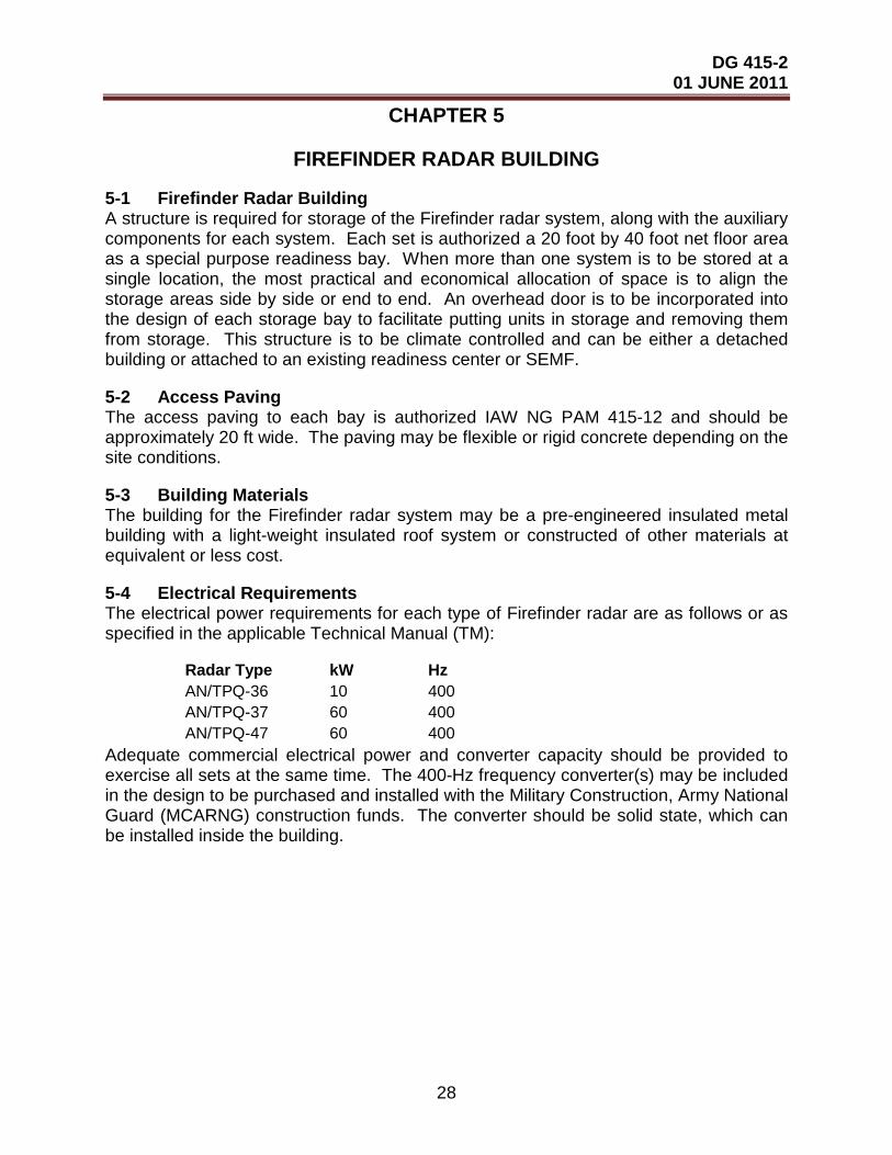
DG 415-2 01 JUNE 2011
28
CHAPTER 5
FIREFINDER RADAR BUILDING
5-1 Firefinder Radar Building A structure is required for storage of the Firefinder radar system, along with the auxiliary components for each system. Each set is authorized a 20 foot by 40 foot net floor area as a special purpose readiness bay. When more than one system is to be stored at a single location, the most practical and economical allocation of space is to align the storage areas side by side or end to end. An overhead door is to be incorporated into the design of each storage bay to facilitate putting units in storage and removing them from storage. This structure is to be climate controlled and can be either a detached building or attached to an existing readiness center or SEMF.
5-2 Access Paving The access paving to each bay is authorized IAW NG PAM 415-12 and should be approximately 20 ft wide. The paving may be flexible or rigid concrete depending on the site conditions.
5-3 Building Materials The building for the Firefinder radar system may be a pre-engineered insulated metal building with a light-weight insulated roof system or constructed of other materials at equivalent or less cost.
5-4 Electrical Requirements The electrical power requirements for each type of Firefinder radar are as follows or as specified in the applicable Technical Manual (TM):
Radar Type kW Hz AN/TPQ-36 10 400 AN/TPQ-37 60 400 AN/TPQ-47 60 400
Adequate commercial electrical power and converter capacity should be provided to exercise all sets at the same time. The 400-Hz frequency converter(s) may be included in the design to be purchased and installed with the Military Construction, Army National Guard (MCARNG) construction funds. The converter should be solid state, which can be installed inside the building.

DG 415-2 01 JUNE 2011
29
CHAPTER 6
UNIQUE ARCHITECTURAL AND ENGINEERING TECHNICAL REQUIREMENTS
(To Be Determined and Developed As Required)

DG 415-2 01 JUNE 2011
30
CHAPTER 7
UNIQUE SUBMISSION REQUIREMENTS
(To Be Determined and Developed As Required)

DG 415-2 01 JUNE 2011
31
CHAPTER 8
UNIQUE DESIGN REVIEW DIRECTIVE REQUIREMENTS
Check List
State shall submit design reviews to ARNG-ILI (ARNG-ILR and ARNG-ILI-C) as follows:
1. Concept drawing at 30%
2. Planning drawing at 60%
3. Final Design at 95%.
4. BFI design at 100%.
(To Be Determined and Developed As Required)

DG 415-2 01 JUNE 2011
32
APPENDIX A
UNIQUE REFERENCES
The following lists criteria in the form of regulations and industry standards that are to be used to design ARNG logistics facilities and are not included in the References in DG 415-5. The design A-E should use the current applicable edition of all references.
GOVERNMENT PUBLICATIONS:
1. Department of the Army
AR 380-380, Automation Security AR 420- 49, Utility Services AR 710-2, Inventory Management Supply Policy Below the Wholesale Level. Military Standard 161f.
2. Department of Justice 2010 ADA Standard for Accessible Design
3. Department of Defense DOD MIL-HDBK-1022A, Petroleum Fuel Facilities.
DG 415-2 01 JUNE 2011
33
APPENDIX B
GLOSSARY
B-1 ACRONYMS AND ABBREVIATIONS ADP automated data processing
A-E architect-engineer
Amp Ampere
AR Army Regulation
ARNG
ARNG-ILI
ARNG-ILS-M
Army National Guard
National Guard Bureau, Installations Division
National Guard Bureau, Logistics Division, Maintenance Branch
AUTODIN automated digital network
BII Basic Items of Issue
CBT Combat
CFMO
CPC
Construction and Facilities Management Officer
Corrosion Prevention Program
CMU concrete masonry unit
COMSEC communication security
CSMS Combined Support Maintenance Shop
DG design guide
DOD U.S. Department of Defense
DODM Department of Defense Manual
F Fahrenheit
FC foot-candle(s)
FMS Field Maintenance Shop

DG 415-2 01 JUNE 2011
34
Ft foot/feet
HVAC heating, ventilation, and air conditioning
Hz Hertz
in. inch(es)
kW kilowatt(s)
Lb pound(s)
MATES Maneuver Area Training Equipment Site
MCARNG Military Construction, Army National Guard
MIL-HDBK Military Handbook
MTOE Modified Table of Organization and Equipment
NPDES National Pollutant Discharge Elimination System
POL petroleum, oils, and lubricants
PVC polyvinyl chloride
SALTI
SAMS-E
summary accounting for low-dollar turnover items
Standard Army Maintenance System-Enhanced
SARSS
SASMO
Standard Army Retail Supply System
Sustainment Automation Support Management Office
SEMF Surface Equipment Maintenance Facility
UPS uninterruptible power system
U.S.C. United States Code
USPFO United States Property and Fiscal Office
UTES Unit Training Equipment Site

DG 415-2 01 JUNE 2011
35
B-2 UNIQUE SPECIALIZED TERMS Surface Equipment Maintenance Facility (SEMF)
An ARNG facility that is used for performing varying levels of maintenance, depending on the mission of the particular shop. The overall mission of a SEMF is to maintain surface equipment at the highest possible operational readiness rate to support training, natural disaster relief, or combat operations.
United States Property and Fiscal Office (USPFO)
An ARNG facility that provides logistical management support, which includes property procurement, inventory transfer transactions, and financial management.
DG 415-2 01 JUNE 2011
36
APPENDIX C
TABLES Table 1. Not Used for Fig 1 Table 2. Not Used for Fig 2 Table 3. Not Used for Fig 3 Table 4. Architectural Interior Finishes Table 5. Doors, Hardware, Storage, and Shelving Table 6. Mechanical Requirements – Part 1, HVAC Table 7. Mechanical Requirements – Part 2, Plumbing Table 8. Electrical Requirements Table 9. Special Equipment and Ceiling Heights

DG 415-2 01 JUNE 2011
37
*Ceiling heights are indicated in Table 9.
Table 4. Architectural Interior Finishes
FUNCTIONAL AREA FLOOR BASE WAINSCOT WALLS CEILING*
Office Areas
1 General Supervisor CPT RB Epoxy GWB/P ACST/ GWB/P
2 Supervisor CPT RB Epoxy GWB/P ACST/ GWB/P
3 Production Controller VCT RB Epoxy GWB/P ACST/ GWB/P
4 Inspection and Library VCT RB Epoxy GWB/P ACST/ GWB/P
5 Automation Clerk CPT RB Epoxy GWB/P ACST/ GWB/P
6 Common IT Space CPT RB Epoxy GWB/P ACST/ GWB/P
7 IT Support Activities CPT RB Epoxy GWB/P ACST/ GWB/P
8 Classroom VCT RB Epoxy GWB/P ACST/ GWB/P
Personnel Areas
1 Toilet/Shower CT CT CT GWB/P (Note 4) GWB/P
2 Locker Room VCT RB Epoxy GWB/P GWB/P 3 Break Area VCT RB Epoxy GWB/P GWB/P 4
Physical Fitness Area
(Note 1)
CPT/RB (Note 8)
Epoxy
GWB/P
ACST
Work Areas 1 Toilet Room CT CT CT CMU EXP/P 2 Supply Room CONC/H - N/A CMU EXP/P
3 Battery Room CONC/H (Note 2) - N/A CMU/P EXP/P
4 Comm. & Electronic Shop RT RB Epoxy CMU/P (Note 5)
EXP/P (Note 5)
5 Instrument Repair Shop RT RB Epoxy GWB/P GWB/P 6 Small Arms Repair Shop CONC/H - N/A CMU/P EXP/P 7 Small Arms Test Room CONC/H - N/A CMU/P EXP/Epoxy 8 Vault (Small Arms) CONC/H - N/A EXP/P EXP/P 9 Vault (CBT Vehicle Arms) CONC/H - N/A EXP/P EXP/P 10
Injection Test Room
CONC/H -
Epoxy
CMU (Note 5)
EXP/P (Note 5)

DG 415-2 01 JUNE 2011
38
Table 4. Architectural Interior Finishes (Continued)
FUNCTIONAL AREA FLOOR BASE WAINSCOT WALLS CEILING*
11 Fuel and Ignition Repair Shop CONC/H - Epoxy CMU (Note 5)
EXP/P (Note 5)
12 BII Storage/Issue CONC/H - Epoxy CMU EXP/P
13 Machine Shop CONC/H (Note 6) - N/A CMU
(Note 5) EXP/P (Note 5)
14 Carpenter Shop CONC/H (Note 6) - N/A CMU
(Note 5) EXP/P (Note 5)
15 Lumber Storage Shed CONC/H - N/A CMU/P EXP/P
16 Canvas Shop CONC/H (Note 7) - N/A CMU/P EXP/P
17 Missile Repair Shop RT RB Epoxy CMU (Note 5)
EXP/P (Note 5)
18 Vault (Missile) CONC/H - N/A EXP/P EXP/P
19 Calibration Room RT RB epoxy CMU (Note 5)
EXP/P (Note 5)
20 Calibration Storage CONC/H - N/A CMU/P EXP/P
21 Glass Repair Room CONC/H - N/A CMU (Note 7) EXP/P
22 Radiator Test & Repair Room CONC/H - N/A CMU (Note 7) EXP/P
23 COMSEC Repair Room CONC/H - N/A CMU/P EXP/P (Note 5)
24 Radiation Calibration Room RT RB Epoxy CMU (Note 5)
EXP/P (Note 5)
25 Bulk POL Storage for Lubricating Systems CONC/H - Epoxy CMU/P EXP/P
26 Bulk POL Storage CONC/H - Epoxy CMU/P EXP/P 27 Controlled Waste Handling CONC/H - Epoxy CMU/P EXP/P 28 Bulk Equipment Storage CONC/H - Epoxy CMU/P EXP/P 29 Flammable Materials Storage CONC/H - Epoxy CMU/P EXP/P 30 Enclosed Unheated Storage CONC/H - N/A EXP/P EXP/P

DG 415-2 01 JUNE 2011
39
TABLE 4 – ABBREVIATIONS ACST acoustical suspended tile, 2 ft by 4 ft or 2 ft by 2 ft
CONC/H clear liquid hardener/sealer finish over exposed concrete floor
CPT carpet – A 26- to 28-oz. (face weight), permanent, static-free (2.5 kV or less), cut or loop pile nylon or acrylic commercial-grade (direct glue down without cushion) carpet is authorized. (Carpet-tile is preferred over rolled stock.)
CT ceramic tile – Thick or thin-set CT and ceramic or marble threshold is authorized
dBA decibels, A-weighted
dSP decibels related to sound pressure of 1 Pascal
EXP/P exposed construction, painted – “Painted” means enamel, latex, or paint of an equivalent cost
GWB/P gypsum wallboard, painted
RB resilient base
RT rubber tile – Static dissipative RT with a static generation of less than 20 volt at 70 °F, 20 percent relative humidity is authorized.
VCT vinyl composition tile– VCT with a thickness of 3/16 in. or less on monolithic concrete finish and with a final wax coat, if recommended by the tile manufacturer, is authorized.
Table 4. Architectural Interior Finishes (Continued)
FUNCTIONAL AREA FLOOR BASE WAINSCOT WALLS CEILING*
Work bays
1 General Purpose Work bay CONC/H - Epoxy CMU (Note 5)
EXP/P (Note 5)
2 Warm-Up Bay CONC/H - Epoxy CMU (Note 5)
EXP/P (Note5)
3 Welding Bay CONC/H - Epoxy CMU (Note 5)
EXP/P (Note 5)
4 Wash Bay CONC/H - Epoxy CMU (Note 5)
EXP/P (Note 5)
5 Paint Stripping Bay CONC/H - Epoxy CMU (Note 5)
EXP/P (Note 5)
6 Paint Preparation Bay CONC/H - Epoxy CMU (Note 5)
EXP/P (Note 5)
7 Paint Booth CONC/H - Epoxy CMU (Note 5)
EXP/P (Note 5)
8
Engine/Transmission Test Cell CONC/H - Epoxy
CMU (Note 5)
EXP/P (Note 5)
9 Electronics Bay CONC/H - Epoxy CMU EXP/P
10 Body Shop CONC/H - Epoxy CMU (Note 5)
CMU (Note 5)
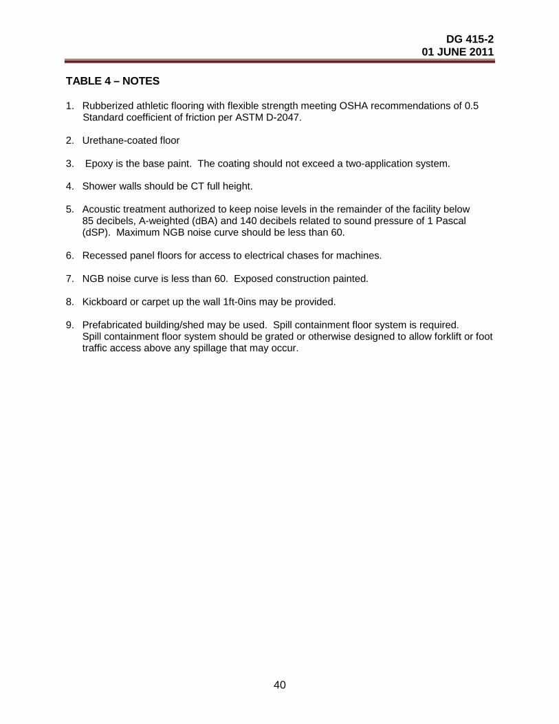
DG 415-2 01 JUNE 2011
40
TABLE 4 – NOTES 1. Rubberized athletic flooring with flexible strength meeting OSHA recommendations of 0.5 Standard coefficient of friction per ASTM D-2047. 2. Urethane-coated floor 3. Epoxy is the base paint. The coating should not exceed a two-application system.
4. Shower walls should be CT full height. 5. Acoustic treatment authorized to keep noise levels in the remainder of the facility below
85 decibels, A-weighted (dBA) and 140 decibels related to sound pressure of 1 Pascal (dSP). Maximum NGB noise curve should be less than 60.
6. Recessed panel floors for access to electrical chases for machines. 7. NGB noise curve is less than 60. Exposed construction painted. 8. Kickboard or carpet up the wall 1ft-0ins may be provided. 9. Prefabricated building/shed may be used. Spill containment floor system is required. Spill containment floor system should be grated or otherwise designed to allow forklift or foot traffic access above any spillage that may occur.

DG 415-2 01 JUNE 2011
41
Table 5. Doors, Hardware, Storage, and Shelving
FUNCTIONAL AREA DOORS HARDWARE STORAGE/SHELVING Office Areas 1 General Supervisor (Note 1) (Note 3) (Note 7) 2 Supervisor (Note 1) (Note 3) (Note 7) 3 Production Controller (Note 1) (Note 3) (Note 8) 4 Inspection and Library (Note 1) (Note 3) (Note 8) 5 Automation Clerk (Note 1) (Note 3) (Note 9) 6 Common IT Space (Note 1) (Note 3) (Note 9) 7 IT Support Activities (Note 1) (Note 2) (Note 10)
8 Classroom
(Note 1) w/glass panel or sidelight
(Note 3) (Note 12)
Personnel Areas 1 Toilet/Shower (Note 1) (Note 2) (N/A) 2 Locker Room (Note 1) (Note 2) (Note 18) 3 Break Area N/A (Note 2) Kitchen-type cabinets 4
Physical Fitness Area
(Note 1) w/glass panel or sidelight
(Note 2)
(N/A)
Work Areas
1 Tool Room (Note 1) (Note 20) (Note 2) (Note 7)
2 Supply Room (Note 1) (Note 21) (Note 2) (Note 7)
3 Battery Room (Note1 & 20) (Note 2) (Note 19) 4
Comm. & Electronic Shop
(Note 1 &/or 23) (Note 2) (Note 7)
5
Instrument Repair Shop
(Note 1 &/or 23) (Note 2) (Note 7)
6 Small Arms Repair Shop (Note 1 &/or 23) (Note 2) (Note 13) 7 Small Arms Test Room (Note 1) (Note 2) (N/A) 8 Vault (Small Arms) IAW AR 190-11 IAW AR 190-11 (Note 24) 9 Vault (CBT) Vehicle Arms IAW AR 190-11 IAW AR 190-11 (Note 24)

DG 415-2 01 JUNE 2011
42
Table 5. Doors, Hardware, Storage, and Shelving (Continued)
FUNCTIONAL AREA DOORS HARDWARE STORAGE/SHELVING 10 Injector Test Room (Note 1 &/or 23) (Note 3) (Note 9)
11 Fuel and Ignition Repair Shop
(Note 1 &/or 23)
(Note 3)
(Note 14)
12 BII Storage/Issue (Note 1 & 25) (Note 3) (Note 9) 13 Machine Shop (Note 1 &/or 23) (Note 3) (Note 15) 14 Carpenter Shop (Note 1 & 25) (note 3) (Note 15) 15 Lumber Storage Shed (Note 1 & 25) (Note 3) (Note 9) 16 Canvas Shop (Note 1 & 25) (Note 3) (Note 9) 17 Missile Repair Shop (Note 1 & 23) (Note 2) (Note 9) 18 Vault (Missile) IAW AR 190-11 IAW AR 190-11 (Note 24) 19 Calibration Room (Note 1 or 23) (Note 3) (note 6) 20 Calibration Storage (Note 1 & 3) (Note 6) 21 Glass Repair Room (Note 1 & 23) (Note 3) (Note 9) 22
Radiator Test & Repair Room
(Note 1 & 25) (Note 3)
(Note 9)

DG 415-2 01 JUNE 2011
43
Table 5. Doors, Hardware, Storage, and Shelving (Continued)
FUNCTIONAL AREA DOORS HARDWARE STORAGE/SHELVING
23 COMSEC Repair Room (Note 1 & 3) (Note 6) N/A 24
Radiation Calibration Room (Note 1) (Note 3)
(Note 6)
25
Bulk POL Storage for Lubricating Systems (Note 10) (N/A)
(Note 9)
26 Bulk POL Storage (Note 20) (N/A)
(Note 9)
27
Controlled Waste Handling (Note 20) (N/A) (Note 9)
28 Bulky Equipment Storage (Note 20) (N/A) (Note 9) 29
Flammable Materials Storage (Note 20) (N/A)
(Note 9)
30
Enclosed Unheated Storage (Note 1 & 20) (Note 3)
(Note 9)
Work bays
1 General Purpose Work Bay (Note 21 & 26) (Note 3) (Note 15)
2 Warm-Up Bay (Note 26) N/A (Note 15) 3 Welding Shop (Note 1 & 26) (Note 3) (Note 16) 4 Wash Bay (Note 26) (N/A) N/A
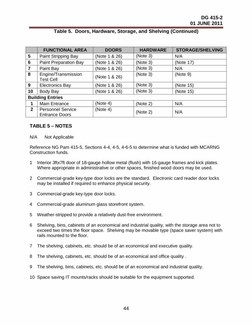
DG 415-2 01 JUNE 2011
44
Table 5. Doors, Hardware, Storage, and Shelving (Continued)
TABLE 5 – NOTES N/A Not Applicable
Reference NG Pam 415-5, Sections 4-4, 4-5, 4-6-5 to determine what is funded with MCARNG Construction funds.
1 Interior 3ftx7ft door of 18-gauge hollow metal (flush) with 16-gauge frames and kick plates. Where appropriate in administrative or other spaces, finished wood doors may be used. 2 Commercial-grade key-type door locks are the standard. Electronic card reader door locks may be installed if required to enhance physical security. 3 Commercial-grade key-type door locks. 4 Commercial-grade aluminum glass storefront system. 5 Weather-stripped to provide a relatively dust-free environment. 6 Shelving, bins, cabinets of an economical and industrial quality, with the storage area not to exceed two times the floor space. Shelving may be movable type (space saver system) with rails mounted to the floor. 7 The shelving, cabinets, etc. should be of an economical and executive quality. 8 The shelving, cabinets, etc. should be of an economical and office quality . 9 The shelving, bins, cabinets, etc. should be of an economical and industrial quality. 10 Space saving IT mounts/racks should be suitable for the equipment supported.
FUNCTIONAL AREA DOORS HARDWARE STORAGE/SHELVING 5 Paint Stripping Bay (Note 1 & 26) (Note 3) N/A 6 Paint Preparation Bay (Note 1 & 26) (Note 3) (Note 17) 7 Paint Bay (Note 1 & 26) (Note 3) N/A 8
Engine/Transmission Test Cell (Note 1 & 26) (Note 3) (Note 9)
9 Electronics Bay (Note 1 & 26) (Note 3) (Note 15) 10 Body Bay (Note 1 & 26) (Note 3) (Note 15) Building Entries 1 Main Entrance (Note 4) (Note 2) N/A 2
Personnel Service Entrance Doors
(Note 4) (Note 2) N/A
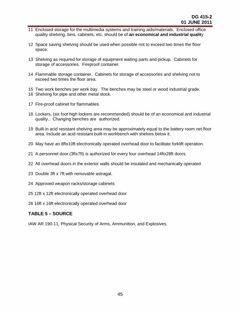
DG 415-2 01 JUNE 2011
45
11 Enclosed storage for the multimedia systems and training aids/materials. Enclosed office quality shelving, bins, cabinets, etc. should be of an economical and industrial quality 12 Space saving shelving should be used when possible not to exceed two times the floor space. 13 Shelving as required for storage of equipment waiting parts and pickup. Cabinets for storage of accessories. Fireproof container. 14 Flammable storage container. Cabinets for storage of accessories and shelving not to exceed two times the floor area. 15 Two work benches per work bay. The benches may be steel or wood industrial grade. 16 Shelving for pipe and other metal stock. 17 Fire-proof cabinet for flammables. 18 Lockers, (six foot high lockers are recommended) should be of an economical and industrial quality.. Changing benches are authorized. 19 Built-in acid resistant shelving area may be approximately equal to the battery room net floor area. Include an acid resistant built-in workbench with shelves below it. 20 May have an 8ftx10ft electronically operated overhead door to facilitate forklift operation. 21 A personnel door (3ftx7ft) is authorized for every four overhead 14ftx28ft doors. 22 All overhead doors in the exterior walls should be insulated and mechanically operated. 23 Double 3ft x 7ft with removable astragal. 24 Approved weapon racks/storage cabinets 25 12ft x 12ft electronically operated overhead door 26 16ft x 16ft electronically operated overhead door TABLE 5 – SOURCE IAW AR 190-11, Physical Security of Arms, Ammunition, and Explosives.
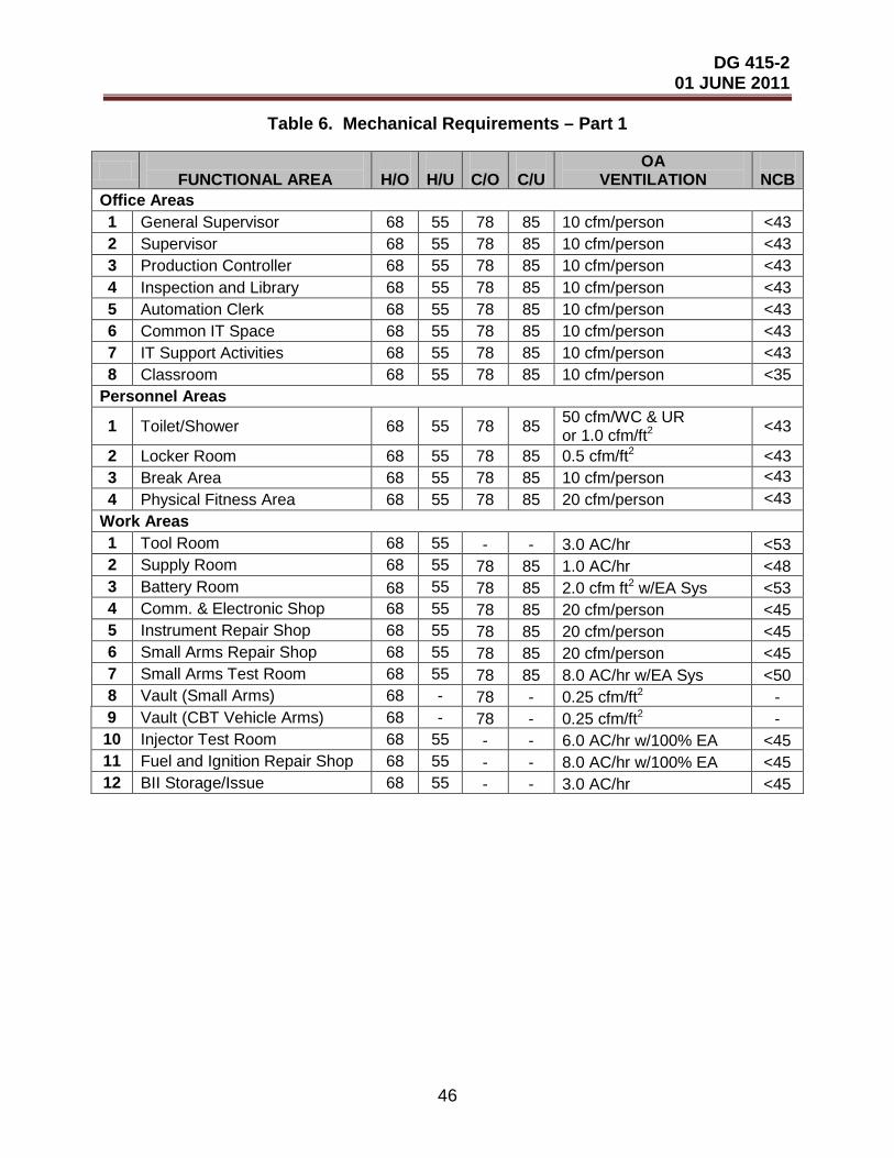
DG 415-2 01 JUNE 2011
46
Table 6. Mechanical Requirements – Part 1
FUNCTIONAL AREA
H/O
H/U
C/O
C/U
OA VENTILATION
NCB
Office Areas 1 General Supervisor 68 55 78 85 10 cfm/person <43 2 Supervisor 68 55 78 85 10 cfm/person <43 3 Production Controller 68 55 78 85 10 cfm/person <43 4 Inspection and Library 68 55 78 85 10 cfm/person <43 5 Automation Clerk 68 55 78 85 10 cfm/person <43 6 Common IT Space 68 55 78 85 10 cfm/person <43 7 IT Support Activities 68 55 78 85 10 cfm/person <43 8 Classroom 68 55 78 85 10 cfm/person <35
Personnel Areas
1 Toilet/Shower 68 55 78 85 50 cfm/WC & UR or 1.0 cfm/ft2 <43
2 Locker Room 68 55 78 85 0.5 cfm/ft2 <43 3 Break Area 68 55 78 85 10 cfm/person <43 4 Physical Fitness Area 68 55 78 85 20 cfm/person <43
Work Areas 1 Tool Room 68 55 - - 3.0 AC/hr <53 2 Supply Room 68 55 78 85 1.0 AC/hr <48 3 Battery Room 68 55 78 85 2.0 cfm ft2 w/EA Sys <53 4 Comm. & Electronic Shop 68 55 78 85 20 cfm/person <45 5 Instrument Repair Shop 68 55 78 85 20 cfm/person <45 6 Small Arms Repair Shop 68 55 78 85 20 cfm/person <45 7 Small Arms Test Room 68 55 78 85 8.0 AC/hr w/EA Sys <50 8 Vault (Small Arms) 68 - 78 - 0.25 cfm/ft2 - 9 Vault (CBT Vehicle Arms) 68 - 78 - 0.25 cfm/ft2 - 10 Injector Test Room 68 55 - - 6.0 AC/hr w/100% EA <45 11 Fuel and Ignition Repair Shop 68 55 - - 8.0 AC/hr w/100% EA <45 12 BII Storage/Issue 68 55 - - 3.0 AC/hr <45
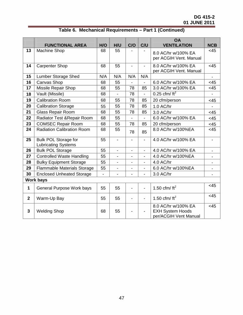
DG 415-2 01 JUNE 2011
47
Table 6. Mechanical Requirements – Part 1 (Continued)
FUNCTIONAL AREA
H/O
H/U
C/O
C/U
OA VENTILATION
NCB
13
Machine Shop
68
55
-
-
8.0 AC/hr w/100% EA per ACGIH Vent. Manual
<45
14
Carpenter Shop
68
55
-
-
8.0 AC/hr w/100% EA per ACGIH Vent. Manual
<45
15 Lumber Storage Shed N/A N/A N/A N/A - 16 Canvas Shop 68 55 - - 6.0 AC/hr w/100% EA <45 17 Missile Repair Shop 68 55 78 85 3.0 AC/hr w/100% EA <45 18 Vault (Missile) 68 - 78 - 0.25 cfm/ ft2 - 19 Calibration Room 68 55 78 85 20 cfm/person <45 20 Calibration Storage 55 55 78 85 1.0 AC/hr - 21 Glass Repair Room 68 55 78 85 3.0 AC/hr <45 22 Radiator Test &Repair Room 68 55 - - 6.0 AC/hr w/100% EA <45 23 COMSEC Repair Room 68 55 78 85 20 cfm/person <45 24
Radiation Calibration Room
68
55 78 85 8.0 AC/hr w/100%EA
<45
25
Bulk POL Storage for Lubricating Systems
55
-
-
-
4.0 AC/hr w/100% EA
-
26 Bulk POL Storage 55 - - - 4.0 AC/hr w/100% EA - 27 Controlled Waste Handling 55 - - - 4.0 AC/hr w/100%EA - 28 Bulky Equipment Storage 55 - - - 4.0 AC/hr - 29 Flammable Materials Storage 55 - - - 6.0 AC/hr w/100%EA - 30 Enclosed Unheated Storage - - - - 3.0 AC/hr - Work bays
1 General Purpose Work bays 55 55 - - 1.50 cfm/ ft2 <45
2 Warm-Up Bay 55 55 - - 1.50 cfm/ ft2 <45
3 Welding Shop 68 55 - - 8.0 AC/hr w/100% EA EXH System Hoods per/ACGIH Vent Manual
<45
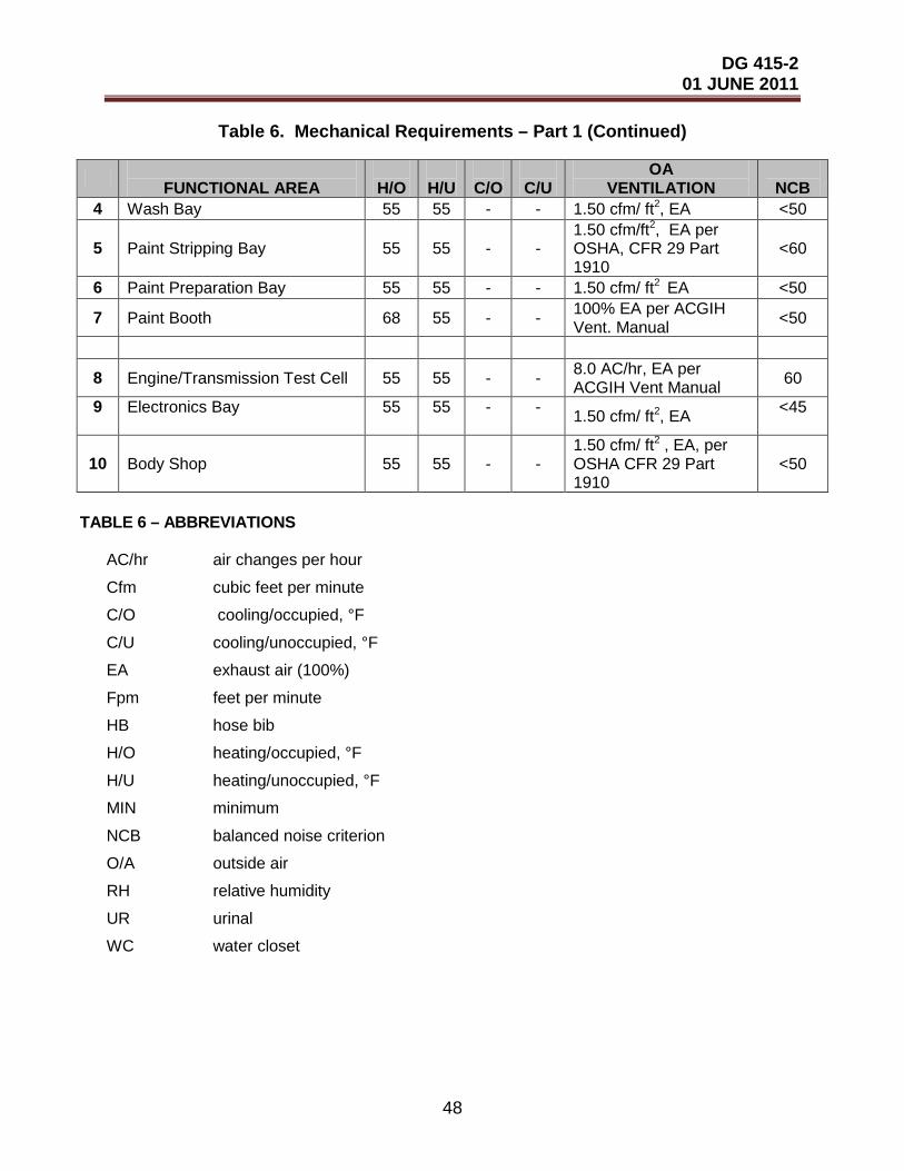
DG 415-2 01 JUNE 2011
48
TABLE 6 – ABBREVIATIONS
AC/hr air changes per hour
Cfm cubic feet per minute
C/O cooling/occupied, °F
C/U cooling/unoccupied, °F
EA exhaust air (100%)
Fpm feet per minute
HB hose bib
H/O heating/occupied, °F
H/U heating/unoccupied, °F
MIN minimum
NCB balanced noise criterion
O/A outside air
RH relative humidity
UR urinal
WC water closet
Table 6. Mechanical Requirements – Part 1 (Continued)
FUNCTIONAL AREA
H/O
H/U
C/O
C/U
OA VENTILATION
NCB
4 Wash Bay 55 55 - - 1.50 cfm/ ft2, EA <50
5 Paint Stripping Bay 55 55 - - 1.50 cfm/ft2, EA per OSHA, CFR 29 Part 1910
<60
6 Paint Preparation Bay 55 55 - - 1.50 cfm/ ft2 EA <50
7 Paint Booth 68 55 - - 100% EA per ACGIH Vent. Manual <50
8 Engine/Transmission Test Cell 55 55 - - 8.0 AC/hr, EA per ACGIH Vent Manual 60
9
Electronics Bay
55
55
-
- 1.50 cfm/ ft2, EA <45
10 Body Shop 55 55 - - 1.50 cfm/ ft2 , EA, per OSHA CFR 29 Part 1910
<50

DG 415-2 01 JUNE 2011
49
TABLE 6 – NOTES
1 Outside Air Ventilation rates are based on ANSI/ASHRAE Standard 62.1-2007 where the supply and return air distribution devices are ceiling mounted. If the distribution devices are located in the occupied zone reduce the air quantity by 50%. Regardless of where the air distribution devices are located the outside air quantity must be at least 15% of the total air circulated HVAC controlled spaces.
2. NCB curves specify noise criteria in various activity areas due to the space itself and all other sources of normal interior and exterior noise due to human occupation. This includes the operation of HVAC systems, the noise produced from equipment and work activities within each area, and noise levels outside the building. 3 Exhaust Systems for special work processes that require an exhaust hood to capture
particles being transported by the air stream must be designed in accordance with the American Conference of Governmental Industrial Hygienists (ACGIH) Industrial Ventilation Manual and ASHRAE Handbooks of Fundamentals and HVAC Applications.
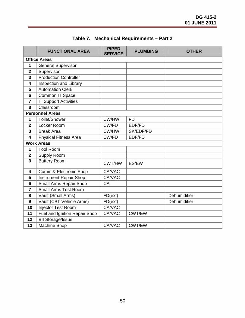
DG 415-2 01 JUNE 2011
50
Table 7. Mechanical Requirements – Part 2
FUNCTIONAL AREA PIPED SERVICE PLUMBING OTHER
Office Areas 1 General Supervisor 2 Supervisor 3 Production Controller 4 Inspection and Library 5 Automation Clerk 6 Common IT Space 7 IT Support Activities 8 Classroom
Personnel Areas 1 Toilet/Shower CW/HW FD 2 Locker Room CW/FD EDF/FD 3 Break Area CW/HW SK/EDF/FD 4 Physical Fitness Area CW/FD EDF/FD
Work Areas 1 Tool Room 2 Supply Room 3
Battery Room CWT/HW ES/EW
4 Comm.& Electronic Shop CA/VAC 5 Instrument Repair Shop CA/VAC 6 Small Arms Repair Shop CA 7 Small Arms Test Room 8 Vault (Small Arms) FD(ext) Dehumidifier 9 Vault (CBT Vehicle Arms) FD(ext) Dehumidifier
10 Injector Test Room CA/VAC 11 Fuel and Ignition Repair Shop CA/VAC CWT/EW 12 BII Storage/Issue 13 Machine Shop CA/VAC CWT/EW
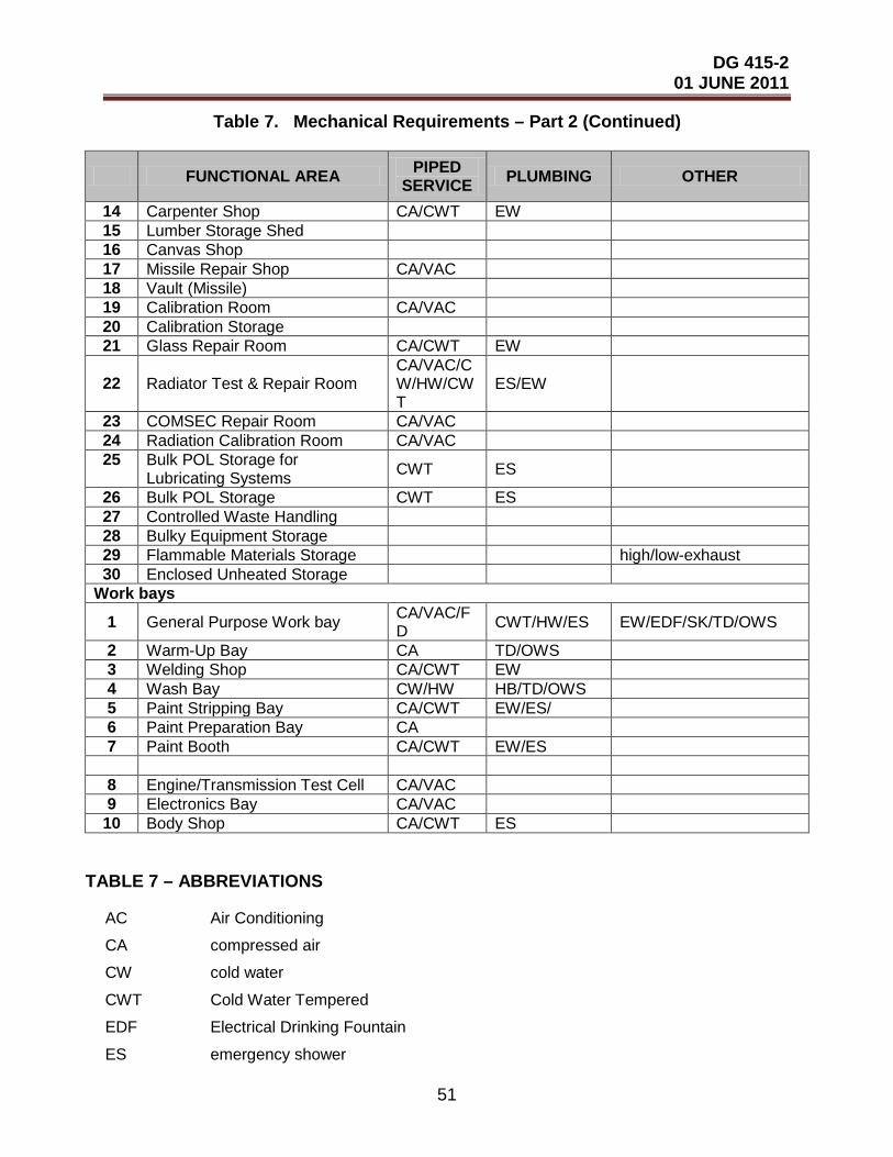
DG 415-2 01 JUNE 2011
51
Table 7. Mechanical Requirements – Part 2 (Continued)
FUNCTIONAL AREA PIPED SERVICE PLUMBING OTHER
14 Carpenter Shop CA/CWT EW 15 Lumber Storage Shed 16 Canvas Shop 17 Missile Repair Shop CA/VAC 18 Vault (Missile) 19 Calibration Room CA/VAC 20 Calibration Storage 21 Glass Repair Room CA/CWT EW
22 Radiator Test & Repair Room CA/VAC/CW/HW/CWT
ES/EW
23 COMSEC Repair Room CA/VAC 24 Radiation Calibration Room CA/VAC 25
Bulk POL Storage for Lubricating Systems CWT ES
26 Bulk POL Storage CWT ES 27 Controlled Waste Handling 28 Bulky Equipment Storage 29 Flammable Materials Storage high/low-exhaust 30 Enclosed Unheated Storage
Work bays
1 General Purpose Work bay CA/VAC/FD CWT/HW/ES EW/EDF/SK/TD/OWS
2 Warm-Up Bay CA TD/OWS 3 Welding Shop CA/CWT EW 4 Wash Bay CW/HW HB/TD/OWS 5 Paint Stripping Bay CA/CWT EW/ES/ 6 Paint Preparation Bay CA 7 Paint Booth CA/CWT EW/ES 8 Engine/Transmission Test Cell CA/VAC 9 Electronics Bay CA/VAC
10 Body Shop CA/CWT ES
TABLE 7 – ABBREVIATIONS
AC Air Conditioning
CA compressed air
CW cold water
CWT Cold Water Tempered
EDF Electrical Drinking Fountain
ES emergency shower

DG 415-2 01 JUNE 2011
52
EW Eyewash
EXT Drain External from Vault
FD Floor Drain
HB Hose Bibb
HW hot water
H heating
OWS Oily Water Separator
SK Sink
TD Trench Drain
VAC vacuum
V ventilation
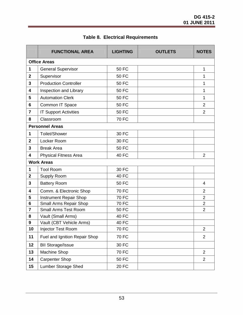
DG 415-2 01 JUNE 2011
53
Table 8. Electrical Requirements
FUNCTIONAL AREA LIGHTING OUTLETS NOTES
Office Areas 1 General Supervisor 50 FC 1 2 Supervisor 50 FC 1 3 Production Controller 50 FC 1 4 Inspection and Library 50 FC 1 5 Automation Clerk 50 FC 1 6 Common IT Space 50 FC 2 7 IT Support Activities 50 FC 2 8 Classroom 70 FC Personnel Areas
1 Toilet/Shower 30 FC 2 Locker Room 30 FC 3 Break Area 50 FC 4 Physical Fitness Area 40 FC 2 Work Areas 1 Tool Room 30 FC 2 Supply Room 40 FC 3 Battery Room 50 FC 4
4 Comm. & Electronic Shop 70 FC 2 5 Instrument Repair Shop 70 FC 2 6 Small Arms Repair Shop 70 FC 2 7 Small Arms Test Room 50 FC 2 8 Vault (Small Arms) 40 FC 9 Vault (CBT Vehicle Arms) 40 FC 10 Injector Test Room 70 FC 2
11 Fuel and Ignition Repair Shop 70 FC 2
12 BII Storage/Issue 30 FC 13 Machine Shop 70 FC 2 14 Carpenter Shop 50 FC 2 15 Lumber Storage Shed 20 FC

DG 415-2 01 JUNE 2011
54
Table 8. Electrical Requirements (Continued)
FUNCTIONAL AREA LIGHTING OUTLETS NOTES
16 Canvas Shop 50 FC 2 17 Missile Repair Shop 70 FC 2 18 Vault (Missile) 40 FC 19 Calibration Room 70 FC 20 Calibration Storage 30 FC 21 Glass Repair Room 50 FC 2 22 Radiator Test & Repair Room 50 FC 2 23 COMSEC Repair Room 70 FC 2 24 Radiation Calibration Room 70 FC
25 Bulk POL Storage for Lubricating Systems 30 FC
26 Bulk POL Storage 30 FC 27 Controlled Waste Handling 30 FC 28 Bulky Equipment Storage 30 FC 29 Flammable Materials Storage 30 FC 30 Enclosed Unheated Storage 30 FC
Work bays 1 General Purpose Work bay 50 FC 2 2 Warm-Up Bay 50 FC 2 3 Welding Shop 50 FC 2 4 Wash Bay 50 FC 2 5 Paint Stripping Bay 50 FC 2 6 Paint Preparation Bay 50 FC 2 7 Paint Booth 50 FC 2
8 Engine/Transmission Test Cell 50 FC 2 9 Electronics Bay 50 FC 2 10 Body Shop 50 FC 2
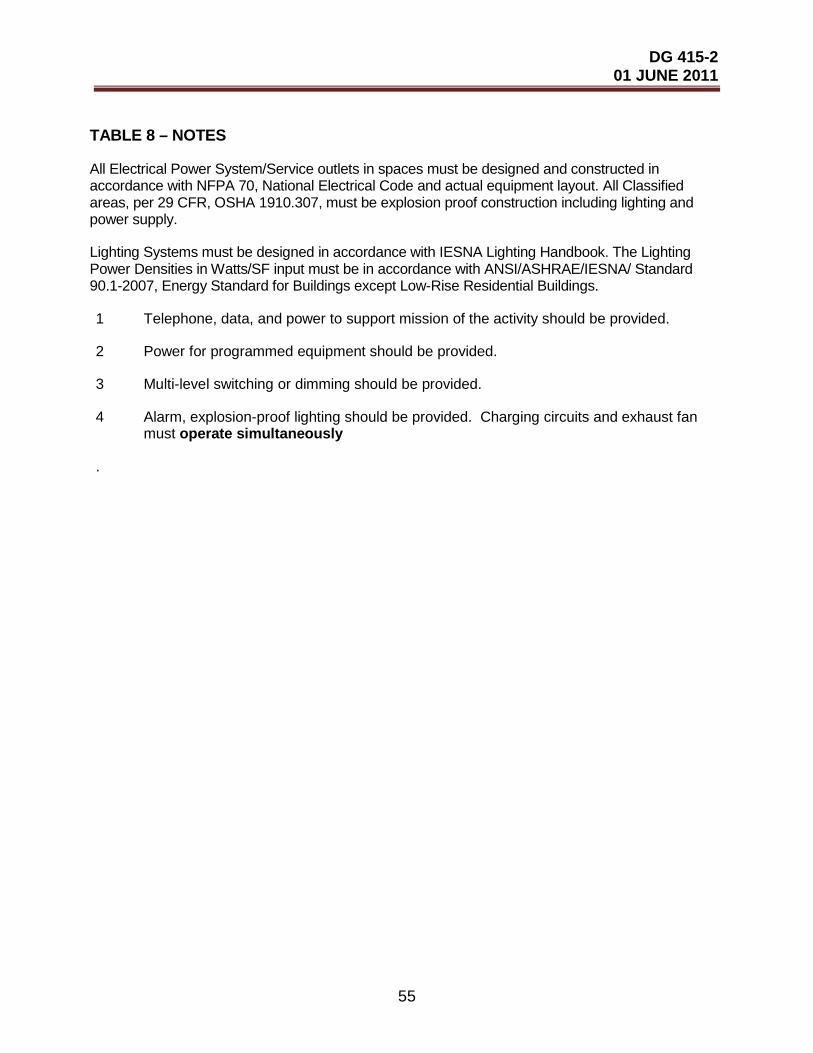
DG 415-2 01 JUNE 2011
55
TABLE 8 – NOTES
All Electrical Power System/Service outlets in spaces must be designed and constructed in accordance with NFPA 70, National Electrical Code and actual equipment layout. All Classified areas, per 29 CFR, OSHA 1910.307, must be explosion proof construction including lighting and power supply.
Lighting Systems must be designed in accordance with IESNA Lighting Handbook. The Lighting Power Densities in Watts/SF input must be in accordance with ANSI/ASHRAE/IESNA/ Standard 90.1-2007, Energy Standard for Buildings except Low-Rise Residential Buildings.
1 Telephone, data, and power to support mission of the activity should be provided.
2 Power for programmed equipment should be provided.
3 Multi-level switching or dimming should be provided.
4 Alarm, explosion-proof lighting should be provided. Charging circuits and exhaust fan must operate simultaneously
.

DG 415-2 01 JUNE 2011
56
Table 9. Special Equipment and Ceiling Heights
FUNCTIONAL AREA SPECIAL EQUIPMENT CEILING* HEIGHT
Office Areas 1 General Supervisor 8 ft 2 Supervisor 8 ft 3 Production Controller 8 ft 4 Inspection and Library 8 ft 5 Automation Clerk 8 ft 6 Common IT Space 8 ft 7 IT Support Activities 8 ft 8 Classroom 10 ft
Personnel Areas 1 Toilet/Shower 8 ft 2 Locker Room 8 ft 3 Break Area 8 ft 4 Physical Fitness Area 10 ft
Work Areas 1 Tool Room 14 ft 2 Supply Room 14 ft 3 Battery Room 10 ft
4 Communications & Electronic Shop 10 ft
5 Instrument Repair Shop 10 ft 6 Small Arms Repair Shop 10 ft 7 Small Arms Test Room 10 ft 8 Vault (Small Arms) Dehumidifier 10 ft 9 Vault (CBT Vehicle Arms) Dehumidifier 10 ft
10 Injector Test Room 15 ft 11 Fuel & Injection Repair Shop 0.5 Ton Crane w/10 ft hook height 15 ft 12 BII Storage/Issue 14 ft 13 Machine Shop 1-Ton Crane w/10 ft. hook height 15 ft 14 Carpenter Shop 14 ft 15 Lumber Storage Shed 14 ft 16 Canvas Shop 0.5 Ton Crane w/14 ft. hook height 18 ft 17 Missile Repair Shop 0.5 Ton Crane w/12 ft hook height 17 ft 18 Vault (Missile) 12 ft

DG 415-2 01 JUNE 2011
57
*Or clearance to underside of structure.
Table 9. Special Equipment and Ceiling Heights (Continued)
FUNCTIONAL AREA SPECIAL EQUIPMENT CEILING* HEIGHT
19 Calibration Room 10 ft 20 Calibration Storage 12 ft 21 Glass Repair Shop 14 ft 22 Radiator Test & Repair Shop 0.5 Ton Crane w/10 ft hook height 15 ft 23 COMSEC Repair Room 12 ft 24 Radiation Calibration Room 12 ft 25
Bulk POL Storage for Lubricating Systems 12 ft
26 Bulk POL Storage 12 ft 27 Controlled Waste Handling 12 ft 28 Bulky Equipment Storage 14 ft
29 Flammable Materials Storage 12 ft
30 Enclosed Unheated Storage 14 ft Work bays
1 General Purpose Work bay 15 Ton Bridge Crane w/ 17 ft hook height 25 ft 2 Warm-Up Bay 25 ft 3 Welding Shop 7.5 Ton Crane w/ 17 ft hook height 25 ft 4 Wash Bay 15 ft 5 Paint Stripping Bay 15 ft 6 Paint Preparation Bay 15 ft 7 Paint Booth 18 ft
8 Engine/Transmission Test Cell 5 Ton Crane w/17 ft hook height 25 ft
9 Electronics Bay 15 ft 10 Body Shop 7.5 Ton Crane w/17 ft hook height 25 ft

DG 415-2 01 JUNE 2011
58
APPENDIX D
FIGURES
Figure 1. Not Used Figure 2. Not Used Figure 3. Not Used


![Bring Wire & Cable Down to Business...25DTP-4-DG compartment pole (power and 25DTP-412 communications). Nominal material 25DTP-412-DG thickness .030" [0.8mm]. Ivory or 25DTP-415 gray](https://static.documents.pub/doc/80x56/5f0808947e708231d41fff0d/bring-wire-cable-down-to-business-25dtp-4-dg-compartment-pole-power-and.jpg)


