24
02/06/22 02/06/22 1 AUTO SYNCHRONIZING AND AUTO AUTO SYNCHRONIZING AND AUTO LOAD SHARING LOAD SHARING
04/11/2304/11/23 11
AUTO SYNCHRONIZING AND AUTO SYNCHRONIZING AND
AUTO LOAD SHARINGAUTO LOAD SHARING
04/11/2304/11/23 22
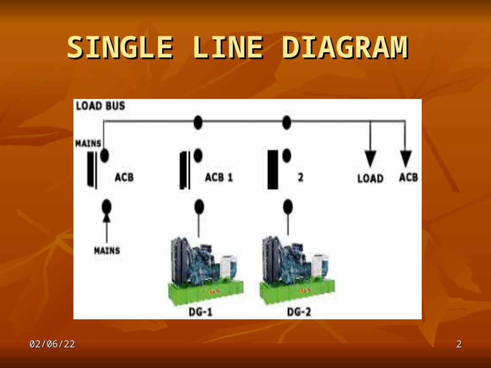
SINGLE LINE DIAGRAM SINGLE LINE DIAGRAM
04/11/2304/11/23 33
When mains are healthy, both the DG’s remain in When mains are healthy, both the DG’s remain in the standby mode. the standby mode.
When mains failWhen mains fail, Line Voltage Monitor , Line Voltage Monitor (L.V.M.) senses. Starting pulses are given to the (L.V.M.) senses. Starting pulses are given to the Master D.G. Set. (Master D.G.Set is automatically Master D.G. Set. (Master D.G.Set is automatically selected by programmer.) selected by programmer.)
After satisfactory starting of the D.G.Set 1, After satisfactory starting of the D.G.Set 1, voltage is sensed by Generator Voltage Monitor voltage is sensed by Generator Voltage Monitor (G.V.M.). If voltage is healthy, then closing signal (G.V.M.). If voltage is healthy, then closing signal is given to D.G.1 breaker and it is closed. is given to D.G.1 breaker and it is closed.
Synchronizing Panel gives corresponding pulses Synchronizing Panel gives corresponding pulses to start load automatically. to start load automatically.
The load is then sensed by KW transducer in the The load is then sensed by KW transducer in the panel & continuously monitored by PLC.panel & continuously monitored by PLC.
04/11/2304/11/23 44
Engine & Alternator parameters are also continuously Engine & Alternator parameters are also continuously monitored by P.L.C. in the Panel. In case of any fault (e.g. monitored by P.L.C. in the Panel. In case of any fault (e.g. Low Lube Oil Pressure, High Cooling Water Temperature Low Lube Oil Pressure, High Cooling Water Temperature etc.), breaker is tripped & engine is stopped. etc.), breaker is tripped & engine is stopped.
If the load reaches & crosses 80 % of the rated capacity of If the load reaches & crosses 80 % of the rated capacity of the D.G. 1, then starting pulses are given to the second the D.G. 1, then starting pulses are given to the second D.G.set by P.L.C. D.G.set by P.L.C.
When D.G.2 starts, then again G.V.M. checks the voltage, When D.G.2 starts, then again G.V.M. checks the voltage, and if voltage is healthy, then breaker 2 is closed. and if voltage is healthy, then breaker 2 is closed.
After closing of the second breaker, Auto load sharing After closing of the second breaker, Auto load sharing function starts sharing the load between the two D.G.Sets. function starts sharing the load between the two D.G.Sets. The percentage of sharing is directly proportional to their The percentage of sharing is directly proportional to their individual capacities. individual capacities.
Since sharing is proportional to their respective capacities, Since sharing is proportional to their respective capacities, even D.G.sets of different capacities can be synchronized even D.G.sets of different capacities can be synchronized successfully. successfully.

04/11/2304/11/23 55
D.G.sets continue to run in Synchronization until the D.G.sets continue to run in Synchronization until the load is above 80 % of any one D.G. set. load is above 80 % of any one D.G. set.
When load comes below 80 % of any one D.G. set, When load comes below 80 % of any one D.G. set, then the automatic signal is given to that D.G. & then then the automatic signal is given to that D.G. & then it starts taking the full load. it starts taking the full load.
After transferring the total load to one D.G. (on After transferring the total load to one D.G. (on which 80 % load is to be connected), the breaker of which 80 % load is to be connected), the breaker of the second D.G.is opened. Now one D.G.is taking the the second D.G.is opened. Now one D.G.is taking the load load
The second D.G. is then stopped after its cooling The second D.G. is then stopped after its cooling period. period.
When mains are resumed, then load is transferred to When mains are resumed, then load is transferred to the mains & both the D.G.sets are stopped after their the mains & both the D.G.sets are stopped after their cooling period.cooling period.
04/11/2304/11/23 66
The total Automatic operation has a manual The total Automatic operation has a manual override. In manual mode, the total operation override. In manual mode, the total operation can be performed manually. can be performed manually.
Auto load shedding facility can be Auto load shedding facility can be incorporated by suitable programming of PLC. incorporated by suitable programming of PLC. With this facility, various loads can be brought With this facility, various loads can be brought in or switched off at particular time or for in or switched off at particular time or for various intervals. various intervals.
04/11/2304/11/23 77
ADVANTAGES OF AUTO SYNCHRONISING & ADVANTAGES OF AUTO SYNCHRONISING &
AUTOLOAD SHARINGAUTOLOAD SHARING Changing of logic is very easy because of changes are made Changing of logic is very easy because of changes are made
through software only. There is no changing of wires, adding through software only. There is no changing of wires, adding of components like relays, contactors, which is very time of components like relays, contactors, which is very time consuming, cumbersome & requiring additional space. consuming, cumbersome & requiring additional space.
For any type of load addition or reduction, manual For any type of load addition or reduction, manual intervention as regards D.G.set operation is not required. intervention as regards D.G.set operation is not required. However, in case of emergency manual override is possible. However, in case of emergency manual override is possible.
Because of KW dependent load sharing, optimum utilization Because of KW dependent load sharing, optimum utilization of D.G. sets are possible. This increases D.G. sets efficiency of D.G. sets are possible. This increases D.G. sets efficiency & saves lot of fuel. & saves lot of fuel.
Use of PLC reduces no. of relays, contactors, wiring etc. This Use of PLC reduces no. of relays, contactors, wiring etc. This reduces fault points & increases the MTBF of the system. reduces fault points & increases the MTBF of the system.
All the future changes / modifications can be easily made All the future changes / modifications can be easily made through software only.through software only.
04/11/2304/11/23 88
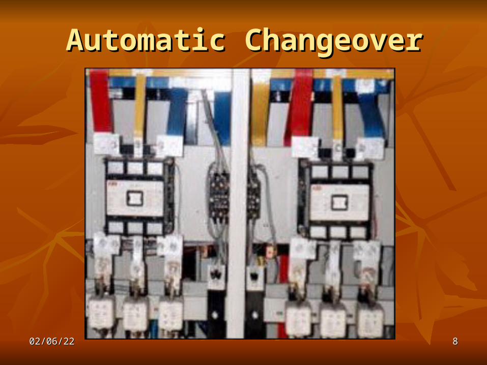
Automatic ChangeoverAutomatic Changeover

04/11/2304/11/23 99
Mains source failureMains source failure Automatic Changeover Switch panel is Automatic Changeover Switch panel is
designed to monitor & to start Generator designed to monitor & to start Generator control panel automatically when the mains control panel automatically when the mains source fails partially or fully. The control source fails partially or fully. The control panel provides a potential-free contact output panel provides a potential-free contact output & provides signal to the remote generator & provides signal to the remote generator control panel to enable automatic start of the control panel to enable automatic start of the generator. generator.
On sensing that the generator is running at On sensing that the generator is running at correct output the changeover switch changes correct output the changeover switch changes over from the mains position to generator over from the mains position to generator position, thereby transferring the site load. position, thereby transferring the site load.
04/11/2304/11/23 1010
When Mains restoresWhen Mains restores L.V.M. checks the mains for its healthiness, L.V.M. checks the mains for its healthiness,
the generator is then disconnected from the the generator is then disconnected from the load and automatic changeover back to the load and automatic changeover back to the mains source takes place. Load is now mains source takes place. Load is now connected to the mains. connected to the mains.
Gen set is then run for about 5 minutes time Gen set is then run for about 5 minutes time set, on no load and it is stopped automatically.set, on no load and it is stopped automatically.
04/11/2304/11/23 1111
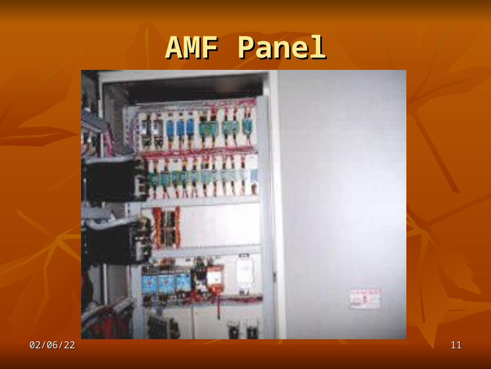
AMF PanelAMF Panel
04/11/2304/11/23 1212
AMF Control panel is designed to monitor & to start AMF Control panel is designed to monitor & to start Generator automatically when the mains source fails partially Generator automatically when the mains source fails partially or fully.or fully.
When mains fail, then it is sensed by Line Voltage Monitor When mains fail, then it is sensed by Line Voltage Monitor (L.V.M.) and three starting pulses are given to Gen set.(L.V.M.) and three starting pulses are given to Gen set.
If Genset does not start within three attempts, then If Genset does not start within three attempts, then ‘STARTING FAILURE’ alarm is sounded and stop signal is ‘STARTING FAILURE’ alarm is sounded and stop signal is given to Genset to stop it fully & no start signals are given given to Genset to stop it fully & no start signals are given further. further.
When Genset starts successfully, it builds up the rated voltage When Genset starts successfully, it builds up the rated voltage and Genset contactor/breaker is closed automatically. The and Genset contactor/breaker is closed automatically. The load then is switched on / transferred to the Genset. load then is switched on / transferred to the Genset.
When Mains restores, which is checked by L.V.M. for its When Mains restores, which is checked by L.V.M. for its healthiness, the generator is then disconnected from the load healthiness, the generator is then disconnected from the load and automatic transfer back to the mains source takes place. and automatic transfer back to the mains source takes place. Load is now connected to the mains.Load is now connected to the mains.

04/11/2304/11/23 1313
Genset is then run for about 5 minutes time Genset is then run for about 5 minutes time set, on no load and it is stopped automatically.set, on no load and it is stopped automatically.
Safeties like L.L.O.P., H.W.T. and over speed Safeties like L.L.O.P., H.W.T. and over speed are operative when the Genset is running. For are operative when the Genset is running. For any of the above faults, Genset stops any of the above faults, Genset stops immediately.immediately.
Automatic function can be totally by-passed Automatic function can be totally by-passed and Genset can be started-stopped in manual and Genset can be started-stopped in manual mode also.mode also.
04/11/2304/11/23 1414
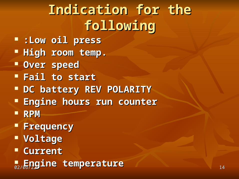
Indication for the followingIndication for the following
:Low oil press:Low oil press High room temp.High room temp. Over speedOver speed Fail to startFail to start DC battery REV POLARITYDC battery REV POLARITY Engine hours run counterEngine hours run counter RPMRPM Frequency Frequency Voltage Voltage CurrentCurrent Engine temperatureEngine temperature
04/11/2304/11/23 1515
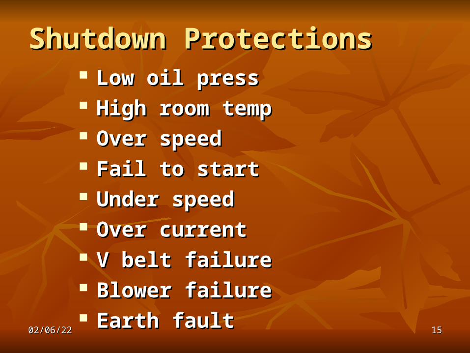
Shutdown ProtectionsShutdown Protections Low oil pressLow oil press High room tempHigh room temp Over speedOver speed Fail to startFail to start Under speedUnder speed Over currentOver current V belt failureV belt failure Blower failureBlower failure Earth faultEarth fault

04/11/2304/11/23 1616
PANEL ACCESSORIESPANEL ACCESSORIES
1 Voltmeter1 Voltmeter 3- Ammeter3- Ammeter 1- Freq. 1- Freq. RPM meterRPM meter Fail to startFail to start 1- Battery voltmeter1- Battery voltmeter 1-Engine hours run counter1-Engine hours run counter 1- Oil press. Gauge1- Oil press. Gauge 1- Engine temp. gauge1- Engine temp. gauge 3- C.T. above 100 A3- C.T. above 100 A
04/11/2304/11/23 1717
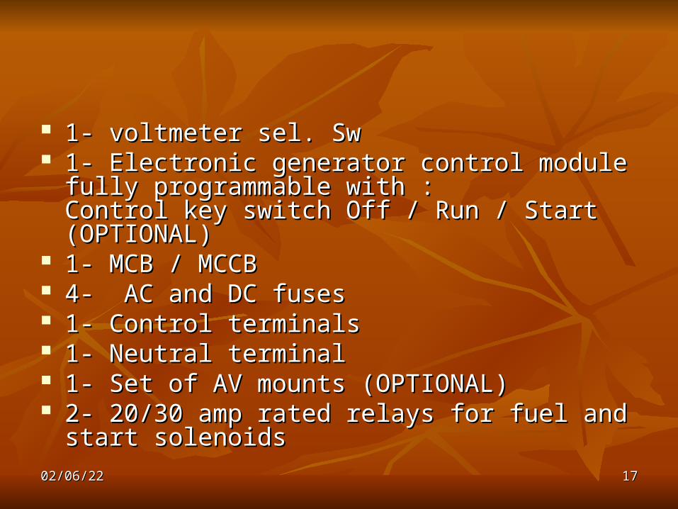
1- voltmeter sel. Sw1- voltmeter sel. Sw 1- Electronic generator control module fully 1- Electronic generator control module fully
programmable with :programmable with :Control key switch Off / Run / Start (OPTIONAL)Control key switch Off / Run / Start (OPTIONAL)
1- MCB / MCCB1- MCB / MCCB 4- AC and DC fuses4- AC and DC fuses 1- Control terminals 1- Control terminals 1- Neutral terminal1- Neutral terminal 1- Set of AV mounts (OPTIONAL)1- Set of AV mounts (OPTIONAL) 2- 20/30 amp rated relays for fuel and start solenoids2- 20/30 amp rated relays for fuel and start solenoids

04/11/2304/11/23 1818
KwKw TRANSDUCERTRANSDUCER

04/11/2304/11/23 1919

04/11/2304/11/23 2020
04/11/2304/11/23 2121
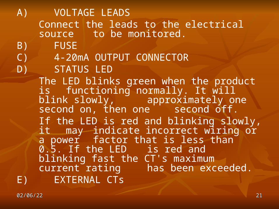
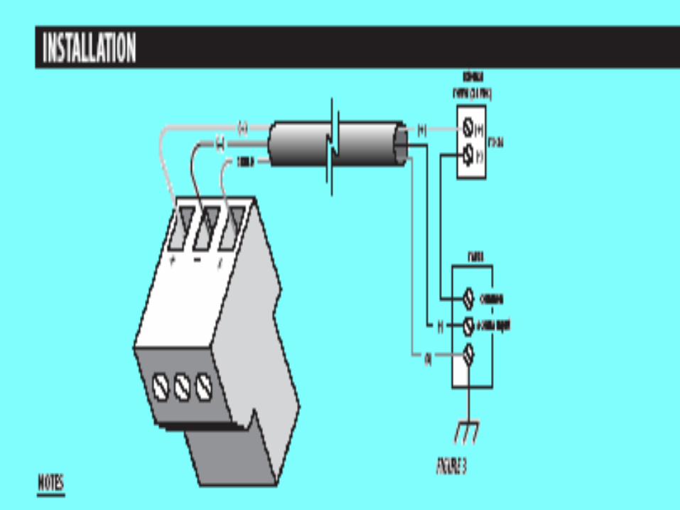
A) VOLTAGE LEADS Connect the leads to the electrical source to be monitored.
B)FUSEC)4-20mA OUTPUT CONNECTOR D) STATUS LED
The LED blinks green when the product is functioning normally. It will blink slowly, approximately one second on, then one
second off. If the LED is red and blinking slowly, it may indicate incorrect wiring or a power factor
that is less than 0.5. If the LED is red and blinking fast the CT's maximum current rating
has been exceeded. E)EXTERNAL CTs
04/11/2304/11/23 2222
04/11/2304/11/23 2323
OPERATION
Kw TRANSDUCER combines a microprocessor based kW transducer and high accuracy split-core current transformers (CTs) in a single unit. Split-core design eliminates the need to remove conductors. Three CT versions is used with three phase, unbalanced loads.
04/11/2304/11/23 2424
Applications
Optimization of chillers, pumps and cooling towers
Energy management & performance contracting
Process control
Real time power monitoring


