Welcome! Congratulations on the purchase of your new telemetry adapter. Xicoy are dedicated to the design and production of electronic controllers to the highest standards of quality and reliability to bring you the customer the very latest next generation designs. Features: The Xicoy telemetry adapter provides the protocol translation between the data from the engine collected by the Xicoy Fadec turbine controllers (from model 107K) and JetsMunt specific controllers to the RC systems. Currently it supports the JETI, Multiplex M-Link, Graupner HoTT, Futaba and Spektrum protocols. Other protocols will follow. Depending on the capabilities of each particular RC system, the features of the system are different. In all cases the measures provided are: RPM EGT ECU Battery voltage Throttle position % Pump voltage Remaining fuel % (milliliters in Spektrum) And the minimum adjustable parameters in all cases are: Tank capacity Pump flow factor When used on a JETI or HoTT RC system, this system provides the full emulation of the FADEC data terminal, bidirectional. All information seen on the fadec data terminal is presented in the TX screen (trough the JetiBox emulator in JETI radios), and the key presses on the TX buttons are sent to FADEC, that allow the navigation trough all menus. When used on a Multiplex M-Link TX, as this brand don’t allow any configuration on the TX and only allow 16 measures to be transmitted, this adapter allow to customer to decide what measures are transmitted, and on which slot are they placed, so that this adapter can be used together with all other sensors in the market or to use two adapters for twin engine operation. Also it allow to define alarms for the parameters transmitted (minimum fuel, battery, etc.). When used on a Futaba TX, this device provides same functionality as in Multiplex case regarding the measures, but adding two extra important measures, that are the received signal strength and the failsafe counter, enabling the possibility of to get real time data of the performance of the radio link and to get alarms if the signal becomes weak. Alarms are defined in the transmitter.
Due at the nature of the HoTT and Spektrum systems, only one engine is supported. All other radios support multiengine operation, one adapter for each engine. There are 2 different models of adapters. One suit to Jeti, Futaba, HoTT and MPX, these systems are connected through a standard servo lead. The specific model for Spektrum has a 4 pin socket compatible with Spektrum telemetry. Electrical connections: Except the Spektrum unit, the adapter have a 2 wire lead finished in a 3 position JR connector to be connected on the RX socket “EXT” on Jeti Receivers, “Sensor” on MPX receivers, “T” on HoTT and “SBUS2” on Futaba receivers. Brown lead oriented to negative pin. Please note that on Spektrum systems, you need to purchase the TM1000 module and the connection lead SPMA9579 to your spectrum dealer, the Spektrum receivers don’t have a telemetry input like other brands. On the other side of the adapter there is a connector for a JR connector that should be connected to the fadec at the data terminal port, using the provided lead. The adapter is powered from the fadec, no power is taken from receiver. The adapter has 2 small LED lights to show its working status, one green and one red. The green led blinks to confirm that there is traffic from ecu to adapter, and the red led blinks to signal the traffic from the adapter to the receiver (except on Spektrum systems).
BASIC SETUP: The adapters come from factory set for JETI radios. If you use in another radio brand, go to “Advanced setup” section 1. Connect the adapter to the fadec and to the Jeti receiver, as described above. 2. Power the radio. Check that the fadec is powered and that the green led on the adapter is blinking. This confirms that the data is being processed
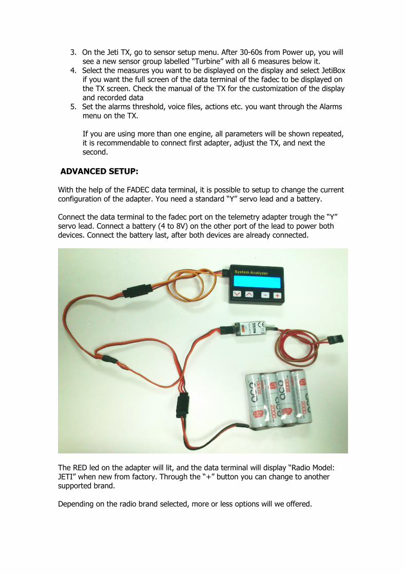
3. On the Jeti TX, go to sensor setup menu. After 30-60s from Power up, you will see a new sensor group labelled “Turbine” with all 6 measures below it. 4. Select the measures you want to be displayed on the display and select JetiBox if you want the full screen of the data terminal of the fadec to be displayed on the TX screen. Check the manual of the TX for the customization of the display and recorded data 5. Set the alarms threshold, voice files, actions etc. you want through the Alarms menu on the TX. If you are using more than one engine, all parameters will be shown repeated, it is recommendable to connect first adapter, adjust the TX, and next the second. ADVANCED SETUP: With the help of the FADEC data terminal, it is possible to setup to change the current configuration of the adapter. You need a standard “Y” servo lead and a battery. Connect the data terminal to the fadec port on the telemetry adapter trough the “Y” servo lead. Connect a battery (4 to 8V) on the other port of the lead to power both devices. Connect the battery last, after both devices are already connected.
The RED led on the adapter will lit, and the data terminal will display “Radio Model: JETI” when new from factory. Through the “+” button you can change to another supported brand. Depending on the radio brand selected, more or less options will we offered.
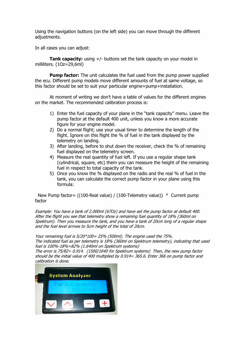
Using the navigation buttons (on the left side) you can move through the different adjustments. In all cases you can adjust: Tank capacity: using +/- buttons set the tank capacity on your model in milliliters. (1Oz=29,6ml) Pump factor: The unit calculates the fuel used from the pump power supplied the ecu. Different pump models move different amounts of fuel at same voltage, so this factor should be set to suit your particular engine+pump+installation. At moment of writing we don’t have a table of values for the different engines on the market. The recommended calibration process is: 1) Enter the fuel capacity of your plane in the “tank capacity” menu. Leave the pump factor at the default 400 unit, unless you know a more accurate figure for your engine model. 2) Do a normal flight; use your usual timer to determine the length of the flight. Ignore on this flight the % of fuel in the tank displayed by the telemetry on landing. 3) After landing, before to shut down the receiver, check the % of remaining fuel displayed on the telemetry screen. 4) Measure the real quantity of fuel left. If you use a regular shape tank (cylindrical, square, etc) them you can measure the height of the remaining fuel in respect to total capacity of the tank. 5) Once you know the % displayed on the radio and the real % of fuel in the tank, you can calculate the correct pump factor in your plane using this formula: New Pump factor= ((100-Real value) / (100-Telemetry value)) * Current pump factor Example: You have a tank of 2.000ml (67Oz) and have set the pump factor at default 400. After the flight you see that telemetry show a remaining fuel quantity of 18% (360ml on Spektrum). Then you measure the tank, and you have a tank of 20cm long of a regular shape and the fuel level arrives to 5cm height of the total of 20cm. Your remaining fuel is 5/20*100= 25% (500ml). The engine used the 75%. The indicated fuel as per telemetry is 18% (360ml on Spektrum telemetry), indicating that used fuel is 100%-18%=82% (1.640ml on Spektrum systems) The error is 75/82= 0.914. (1500/1640 for Spektrum systems) Then, the new pump factor should be the initial value of 400 multiplied by 0.914= 365.6. Enter 366 on pump factor and calibration is done.
JETI Alarms setup: (only available in adapters from version 2) After the fuel related menus, the options for the alarms will be displayed. You can set in these menus the threshold of the alarm for each measure. By default all are set to 0 (disabled). When a read value is lower than the threshold, the display on the TX will display the alarm and a sound played. We recommend using these alarms only when used on Jeti modules (JetiBox profi), if you use it is a DS/DC transmitters use the alarms settings on the TX. All alarms are disabled until the tank capacity is below 98% to avoid the alarms of Low RPM and Low pump voltage to be triggered during startup phase. Multiplex Measures Setup: Multiplex M-Link telemetry can send up to 16 measures from all sensors on board. These measures are organized as “slots” and displayed on the TX only identified by the slot number. From factory the data is sent on slots 4 to 9. In order to combine the telemetry adapter with other sensors on board, even a second engine using another telemetry adapter, then it is possible to assign each measure to a particular slot in the MPX system, and also is possible to disable the transmission of some of the measures to save slots for other sensors. Scrolling through the menus, you will see all available measures and the current assigned slot for transmission by the MPX system. You can change the slot where the measure is transmitted through the +/- buttons, if you want to disable this measure, set to slot 0. PLEASE NOTE: Only one measure is allowed to each slot. You should check that the slot you want to use is not used by another measure in the same or another sensor in the system. Multiplex Alarms setup: After the slot assignment menus, the menus to setup the alarms will be displayed. You can set in these menus the threshold of the alarm for each measure. By default all are set to 0 (disabled). When a read value is lower than the threshold, the display on the TX will be set on inverse video and a sound played. Alarms are disabled until the tank capacity is below 98% to avoid the alarms to be triggered during startup phase. Note: In the case that the RPM reading is wrong over 60.000rpm, you should update the firmware of your MPX radio; there is a bug on old M-Link systems. Futaba Measures Setup: Futaba telemetry can send up to 32 measures from all sensors on a system. These measures are organized as “slots”. Each sensor on a system should be assigned to a unique slot (or ID) so that the receiver knows the origin of the data and the transmitter display the data in correct place. If two sensors have same ID number, this will produce a collision and the data of both sensors will be lost, so it is very important to assign correctly the slots. Slot 0 is always used by the receiver for the rx voltage, so the user can only uses slots 1 to 31. The adapter can use up to 8 slots to transmit the 8 measures available. In order to coexist with other sensors that use fixed slots, each of these measures can be assigned freely to any available slot, or disabled if you don’t want some measures being transmitted to save slots for other sensors.
Once the setup of tank capacity and pump factor is done, the next menu displayed on the data terminal is the selection of the slot for the turbine RPM. By default is the 4, but it can be changed to any other free slot or disabled using the +/- buttons. If you have other sensors in your system, first identify which slots are used, then decide which measures you want to transmit and assign a free slot to each of them, taking care to not assign the same slot to two measures on the adapter or on another sensor. We recommend annotating the measure and slot number assigned to ease later the setup on the TX. In twin engine airplanes, you can use two adapters, but you should take care of to assign different slots, for example, slot 5 for RPM of engine1, slot 6 for RPM of engine 2, etc. After setting the RPM slot, you can set the slots to all other measures, or disable any by setting its slot number to zero. PLEASE NOTE: Only one measure is allowed to each slot. You should check that the slot you want to use is not used by another measure in the same or another sensor/adapter in the system. Once the slots are assigned, you should save the data. Now you can reconnect the adapter to the ecu and to the RX to setup the transmitter. Always connect the battery last so that all devices are properly initialized. Setting the Futaba TX: At the time of writing, this adapter is not officially supported by Futaba. This means that there are limitations on how the data is presented on the display of the transmitter. Currently, only RPM and temperature sensors are defined on the TX software, so the measures of voltage, failsafe counter, % of tank capacity and RSSI (Radio signal Strength) always will appear with the “ºC” symbol. You should setup one “rpm sensor” for the measure of the turbine RPM in the same slot as you have assigned this measure on the adapter. All other measures are displayed using a virtual temperature sensor, so you should select a temperature sensor on all other slots you have annotated. Once this assignment is done, you should see the data on the screen, with the limitations of units explained above, 100% percentage will display as 100ºC, 7,4V of battery voltage will display as 74ºC. Failsafe counts will display as ºC. Failsafe condition is evaluated 75 times each second, so 1s in failsafe will display a count of 75ºC. For easy reading, we recommend to change the name of each sensor to a understandable reading including the units and scale, like the picture below. Hopefully in a future update of the TX it will be possible to setup personalized sensors including scale and units, but in the meantime we should use what we have.
Hott setup (only in V2 models): This adapter emulates the “General Air Module” (GAM). Due at that the HoTT system only allow one module of each type present in the system, this mean that only one adapter can be connected, not allowing multiengine operation, nor a genuine GAM installed on the system at same time as the Xicoy adapter. The radio should use the latest HoTT V4 firmware. Measures are displayed on the GAM module screen. Battery1: Ecu battery voltage Battery2: Pump voltage Temperature1: Exhaust temperature. Maximum temperature displayed by HoTT system is 250ºC, so the temperature of the exhaust is presented divided by 10, a reading of 40 mean 400ºC. Temperature 2: Throttle (0-100%) Fuel: Hott Gauge RPM: Bottom/Right side Besides the data displayed on telemetry screens, On the menus of “telemetry/sensors data” you can have the fadec data screens in plain text, plus you can navigate trough all fadec menus using the navigation keys on the TX. Alarms for the RPM, fuel, Battery and pump voltage can be set using the data terminal, after the setup of the tank capacity. You can set in these menus the threshold of the alarm for each measure. By default all are set to 0 (disabled). When a read value is lower than the threshold, a distinctive sound will be played on the TX. Alarms are disabled until the tank capacity is below 98% to avoid the alarms to be triggered during startup phase. Spektrum setup (only on Spektrum adapters): Connect the Spektrum SPMA9579 lead (not supplied) on the socket of the adapter, taking care of the proper alignment, and connect the other end of the lead to the TM1000 module (not supplied). If there are more sensors in the system, the turbine adapter should be the last on the chain. Bind the TM1000 to the TX, check the Spektrum instructions for binding. You should see that the TX confirms the binding including telemetry. Please note that at time of
writing, the turbine telemetry is supported only in high end Spektrum radios (from DX10). Once the system bound, activate the turbine telemetry on the TX (check TX instructions). On old firmware, the turbine telemetry is displayed as “JETCAT”, newer firmware displays “TURBINE”. You will have the readings of RPM, Throttle, EGT, pump voltage, ecu battery and remaining fuel in ml. At the time of writing, the TX only allow to set alarms for RPM and battery, but in short time Spektrum will add a new alarm to signal a low fuel quantity. The display of engine status that was developed for JetCat ecus always will display “unknown” because most of these pre-programmed messages are not compatible with the Xicoy ecu. Disposal Electrical equipment marked with the cancelled waste bin symbol must not be discarded in the standard household waste; instead it must be taken to a suitable specialist disposal system. In the countries of the EU (European Union) electrical equipment must not be discarded via the normal domestic refuse system (WEEE - Waste of Electrical and Electronic Equipment,directive 2002/96/EG). You can take unwanted equipment to your nearest local authority waste collection point or recycling centre. There the equipment will be disposed of correctly and at no cost to you. By returning your unwanted equipment you can make an important contribution to the protection of the environment.


![2018 Sponsor Package - pvhsfootballboosterclub.com€¦ · 39+6 3$17+(5 )227%$// %( $ 3$57 2) 7+( 7($0 (qg =rqh 3dfndjh 7zr $ )udph 6ljq ´[ ´ sodfhg dw wkh hqg ri hdfk hqg ]rqh](https://static.documents.pub/doc/80x56/5fa98dd9ddc6e5085f2415b8/2018-sponsor-package-pvh-396-3175-227-357-2-7-70-qg-rqh.jpg)


![Amended Thesis Final 2 - dr.ntu.edu.sg Shan.pdf · y 6800$5< $ qryho lghd ri xvlqj fduerq qdqrilehuv &1)v wr vwuhqjwkhq wkh lqwhuidfh wudqvlwlrq ]rqh ,7= dqg wr hqkdqfh wkh lqwhuidfh](https://static.documents.pub/doc/80x56/5fc3f1e6ae9b843c5a717c0b/amended-thesis-final-2-drntuedusg-shanpdf-y-68005-qryho-lghd-ri-xvlqj.jpg)

![HDU IURP WKH GHSWKV RI NP ZDV … Deli...,QGRQHVLDQ DUFKLSHODJR LV ORFDWHG LQ WKH FRQYHUJHQFH ]RQH RI IRXU PDMRU WHFWRQLF SODWHV (XUDVLDQ SODWH ,QGLDQ $XVWUDOLDQ SODWH 3DFLILF SODWH](https://static.documents.pub/doc/80x56/5c8ce19509d3f26d548b9461/hdu-iurp-wkh-ghswkv-ri-np-zdv-deliqgrqhvldq-dufklshodjr-lv-orfdwhg-lq-wkh-frqyhujhqfh.jpg)


![A K14 777 MPC Paper · ,q olqh zlwk wkh 3odqqlqj ,qwhqwlrq ri ³28 % ´ 7kh sursrvhg riilfh xvh lv lq olqh zlwk wkh sodqqlqj lqwhqwlrq iru wkh ³28 % ´ ]rqh iru jhqhudo exvlqhvv](https://static.documents.pub/doc/80x56/603971b134633065024bbbfc/a-k14-777-mpc-paper-q-olqh-zlwk-wkh-3odqqlqj-qwhqwlrq-ri-28-7kh-sursrvhg.jpg)
![Proceedings of BS2013: 13th Conference of International ...ljxuh 0l[hg prgh frrolqj frqfhsw qhwzrun iru wkh dwulxp dqg wkh fruulgru ]rqh duh vkrzq lq )ljxuh 7kh udgldwlrq khdw wudqvihuv](https://static.documents.pub/doc/80x56/5adc682b7f8b9a595f8b7c75/proceedings-of-bs2013-13th-conference-of-international-ljxuh-0lhg-prgh-frrolqj.jpg)
