Page 1 of 52 8000-INS-UMENG Rev. 3 DGH 8000 (SCANMATE-B) ULTRASONIC B-SCAN B Scanmate DGH 8000 OPERATOR’S MANUAL For Use with Scanmate Software v4.1.x Equipment Manufactured By Authorized Representative 0120 M 2 T P EC REP EMERGO EUROPE Prinsessegracht 20 2514 AP, The Hague The Netherlands DGH TECHNOLOGY, INC. 110 SUMMIT DRIVE SUITE B EXTON, PA 19341 USA (610) 594-9100
Transcript
Page 1 of 52 8000-INS-UMENG Rev. 3
DGH 8000 (SCANMATE-B)
ULTRASONIC B-SCAN
BScanmate DGH 8000
OPERATOR’S MANUAL
For Use with Scanmate Software v4.1.x
Equipment Manufactured By Authorized Representative
0120
Molenstraat 15
2513 BH, The HagueThe NetherlandsPhone: +31.70.345.8570
EC REP
EMERGO EUROPEDGH TECHNOLOGY, INC.110 SUMMIT DRIVESUITE B
EXTON, PA 19341USA (610) 594-9100
Molenstraat 15
2513 BH, The HagueThe NetherlandsPhone: +31.70.345.8570
EC REP
EMERGO EUROPEDGH TECHNOLOGY, INC.110 SUMMIT DRIVESUITE B
EXTON, PA 19341USA (610) 594-9100
Prinsessegracht 20 2514 AP, The Hague The Netherlands
Molenstraat 15
2513 BH, The HagueThe NetherlandsPhone: +31.70.345.8570
EC REP
EMERGO EUROPEDGH TECHNOLOGY, INC.110 SUMMIT DRIVESUITE B
EXTON, PA 19341USA (610) 594-9100
Page 2 of 52 8000-INS-UMENG Rev. 3
This page intentionally left blank.
Page 3 of 52 8000-INS-UMENG Rev. 3
TABLE OF CONTENTS
1 GENERAL DEVICE DESCRIPTION................................................................................ 5 2 DEVICE CLASSIFICATION ............................................................................................. 5 3 INDICATIONS FOR USE .................................................................................................. 5 4 WARNINGS AND CAUTIONS ........................................................................................ 6
4.1 Meaning of Signal Words ............................................................................... 6 4.2 Description of Symbols .................................................................................. 6 4.3 General Cautions and Warnings ..................................................................... 7
7 USE OF ULTRASOUND IN OPHTHALMIC DEVICES ................................................. 9
8 ULTRASONIC EXPOSURE AND INTENSITIES ........................................................... 9 8.1 Tissue Exposure to Ultrasound Energy .......................................................... 9
12.3 Doctor Preferences ......................................................................................... 16 13 THE PATIENT DATA SCREEN ..................................................................................... 18
13.1 Patient Data Screen Controls ........................................................................ 18
13.2 Entering a New Patient ................................................................................. 19 13.3 Searching for a Patient .................................................................................. 20
13.4 Editing a Patient Record ............................................................................... 20 14 THE A-SCAN SCREEN ................................................................................................... 21 15 THE B-SCAN SCREEN ................................................................................................... 22
15.1 Selecting the Probe ........................................................................................ 22 15.2 Adjusting Pulse Power ................................................................................... 23
15.3 Selecting the Operator ................................................................................... 23
15.4 Selecting OD or OS ....................................................................................... 23
22 CARE AND MAINTENANCE ........................................................................................ 46
22.1 Care of the USB Probe................................................................................... 46 22.2 Maintenance of the USB Probe ..................................................................... 46 22.3 Operating Conditions ..................................................................................... 46
APPENDIX A COMPUTER SYSTEM SPECIFICATIONS............................................... 50 APPENDIX B SUMMARY OF ACOUSTIC OUTPUT (12.0 MHZ PROBE) ................... 51
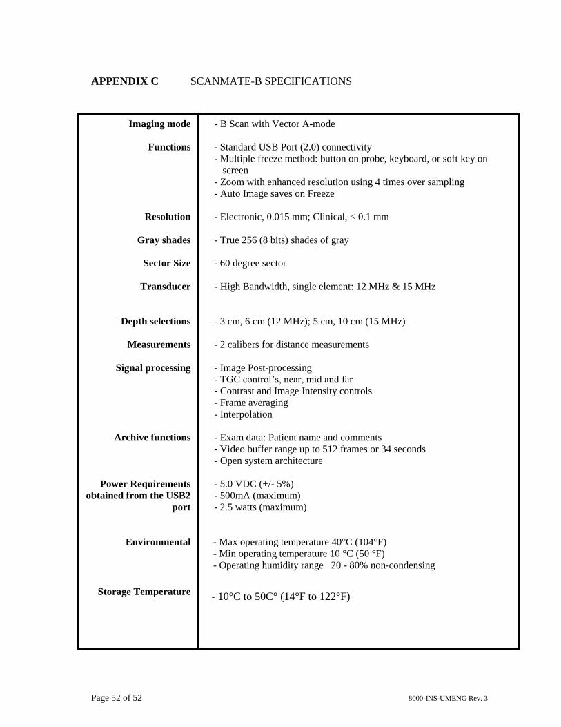
APPENDIX C SCANMATE-B SPECIFICATIONS ........................................................... 52
Page 5 of 52 8000-INS-UMENG Rev. 3
1 General Device Description
The DGH 8000 is a diagnostic ultrasound device used by professionals in the
ophthalmic field to produce cross-sectional images of the eye and orbit. The probe is
comprised of a 12 MHz, single element transducer that is mechanically oscillated to
perform a 60-degree sector scan of the eye. The probe hand piece contains the
electronics used to pulse the transducer as well as to measure, filter and amplify the
resulting echoes from intraocular and orbital tissue. The probe is powered and controlled
via a USB 2.0 cable, which must be connected to a PC or Laptop running the Scanmate
software. The Scanmate software interprets the digital signals transmitted by the probe
and displays a “Brightness Scan” that shows the relative magnitude of the echo spikes
received by the transducer. The software allows the user to adjust the scan rate of the
probe (12 or 15 MHz) as well as the gain, contrast, intensity, and depth of the displayed
image. Once the exam is complete, the application allows the user to save video(s),
image(s) or create a report to document the results.
2 Device Classification
Device: System, Imaging, Pulsed Echo, Ultrasonic
Panel: Radiology
Product Code: IYO
Device Class: II
Regulation Number: 21 CFR 892.1560
3 Indications for Use
The DGH 8000 Scanmate-B is an ultrasonic device used by professionals in the
ophthalmic field to perform a “Brightness Scan” of the eye. The main function of the
device is to produce cross-sectional images of the eye and orbit and to serve as an aid in
the detection and assessment of physical and functional abnormalities using established
diagnostic criteria.
Page 6 of 52 8000-INS-UMENG Rev. 3
0120
4 Warnings and Cautions
4.1 Meaning of Signal Words
In this manual, the signal words “Warning” and “Caution” are used to highlight
important safety and usage instructions. All users of the DGH 8000 must understand the
meanings of these signal words.
Signal Word Meaning
! WARNING
Indicates a potentially hazardous situation which if not avoided
could cause injury or harm to the equipment or erroneous
results.
! CAUTION
Indicates a potentially hazardous situation which if not avoided
may result in minor injury or harm to the equipment.
4.2 Description of Symbols
This symbol indicates the degree of protection against electric shock. The
DGH 8000 Scanmate-B is classified as type BF equipment.
This symbol instructs the operator to read the operating manual.
This mark indicates that Notified Body 0120 (SGS United Kingdom Ltd) has
certified the management system of DGH Technology, Inc. meets the
requirements applicable requirements of 21 CFR 1010 (Performance
Standards for Electronic Products: General) and 21 CFR 1050 (Performance
Standards for Sonic, Infrasonic, and Ultrasonic Radiation-Emitting
Products). The device also conforms to the following International
Standards:
▪ EN 60601-1: Medical electrical equipment – Part 1: General
requirements for safety – IEC 60601-1
▪ EN 60601-1-2: Medical electrical equipment – Part 1: General
requirements for safety. Collateral standard: Electromagnetic
compatibility requirements and tests. IEC 60601-1-2
▪ NEMA Standard Publication UD-2: Acoustic Output Measurement
Standard for Diagnostic Ultrasound Equipment
▪ NEMA Standard Publication UD-3: Standard for Real-Time Display
of Thermal and Mechanical Acoustic Output Indices on Diagnostic
Ultrasound Equipment
Page 7 of 52 8000-INS-UMENG Rev. 3
This symbol indicates that Emergo Europe is the European Authorized
Representative for this device.
This symbol indicates that DGH Technology, Inc. is the manufacturer of the
DGH 8000 Scanmate-B device. The YYYY under the symbol indicates the
year the device was manufactured.
This symbol indicates that the model number of this device is DGH 8000.
This symbol indicates the serial number of the device. YYYY indicates
the year of manufacture and XXXX indicates the unit number.
This symbol located on the DGH 8000 indicates that the equipment consists
of electronic assemblies and other components that may be subject to
Directives 2002/96/EC, 2003/108/EC, and 2002/95/EC of the European
parliament, which advises that electrical and electronic devices must not be
disposed of as normal domestic refuse. In order to prevent environmental
risks or endangerments by non-professional disposal, the disposal of this
product, including any accessories, must comply with valid practices as
outlined in Directives 2002/96/EC, 2003/108/EC, and 2002/95/EC and local
regulations. All electronic components and systems should be returned to
Original Manufacturer for disposal.
4.3 General Cautions and Warnings
! CAUTION
The probe must be cleaned after each use. Cleaning the transducer is an essential
step prior to effective disinfection. Follow the manufacturer’s instructions when
using disinfectants.
! WARNING
Do not allow sharp objects, such as scalpels or cauterizing knives, to touch the
probe or cables.
! WARNING
Equipment not suitable for use in the presence of flammable mixtures.
EC REP
yyyy
REF
SN
Page 8 of 52 8000-INS-UMENG Rev. 3
5 Prescription Device Statement
6 Operator Qualifications
This DGH 8000 is intended to be used by trained medical professionals. The medical
professional operating the DGH 8000 must have a general knowledge of the use of
ultrasonic imaging devices and imaging protocols.
! WARNING
If the probe is used with other devices, current leakage may increase and electric
shock may be caused. It is the user’s responsibility to ensure safety when the
probe is to be used with other devices. If safety cannot be ensured, use of the
probe with other devices is not allowed.
! WARNING
The use of a “Non-Medical” grade AC Adapter could potentially cause harm to
the system, the probe, the operator and/or the patient.
! CAUTION
The DGH 8000 is a prescription device and is only to be used by, or under the
supervision of, a licensed physician.
Page 9 of 52 8000-INS-UMENG Rev. 3
7 Use of Ultrasound in Ophthalmic Devices
Ultrasound offers a non-invasive method to examine the interior of solid objects.
Ultrasonic pulses consist of sound waves of a frequency level too high to be heard by
the human ear. When a sound impulse strikes an interface, some sound is reflected, and
some sound is transmitted. Because some sound will pass through the surface and be
reflected by the next surface, complex structures can be examined with ultrasound.
When ultrasound penetrates an object with several interfaces, the reflected ultrasound
can be observed on a display as a “Brightness Scan” that shows the relative position and
magnitude of the echo spikes received by the transducer.
Note: Ultrasound cannot travel through air because air is not dense enough for the high
frequency waves to propagate. Ultrasonic measurements must therefore be
performed by direct contact or through a denser medium such as coupling gel or
water.
8 Ultrasonic Exposure and Intensities
8.1 Tissue Exposure to Ultrasound Energy
The ultrasound energy emitted by the DGH 8000 is low intensity and will have no
adverse effects on the patient and/or operator. However, the operator is still cautioned to
perform examinations using the principle of ALARA (As Low As Reasonably
Achievable). All examinations should be done so that the patient receives as little
ultrasound radiation as possible. Do not hold the probe against the eye or other tissue
with the system activated except when performing an exam. Do not perform
unnecessary exams.
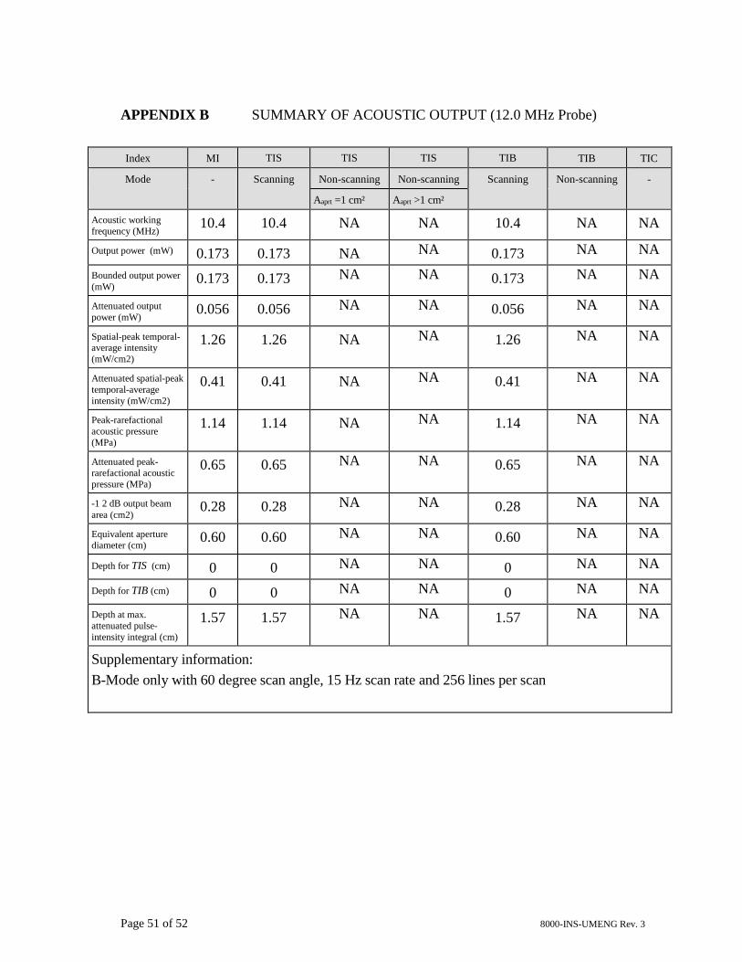
8.2 Ultrasonic Intensities
See Appendix B of this manual for acoustic measurements.
9 Biometric Imaging Capabilities
The following table shows the resolution for the DGH 8000 Scanmate-B.
Parameter Electronic Clinical
Resolution 0.015 mm < 0.1mm
Page 10 of 52 8000-INS-UMENG Rev. 3
10 Installation and Configuration of Scanmate Software
Refer to the Scanmate Installation Manual for information on installing and configuring
the software.
11 Starting the Scanmate Software
11.1 Launching the Application
Once installed, the “Scanmate” shortcut appears on the Windows desktop
and in the start menu. Click on the desktop icon to start the DGH
Scanmate application.
11.2 Splash Screen
The Scanmate splash screen will appear while the application loads.
Page 11 of 52 8000-INS-UMENG Rev. 3
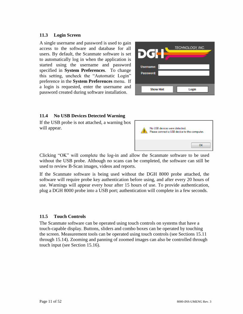
11.3 Login Screen
A single username and password is used to gain
access to the software and database for all
users. By default, the Scanmate software is set
to automatically log in when the application is
started using the username and password
specified in System Preferences. To change
this setting, uncheck the “Automatic Login”
preference in the System Preferences menu. If
a login is requested, enter the username and
password created during software installation.
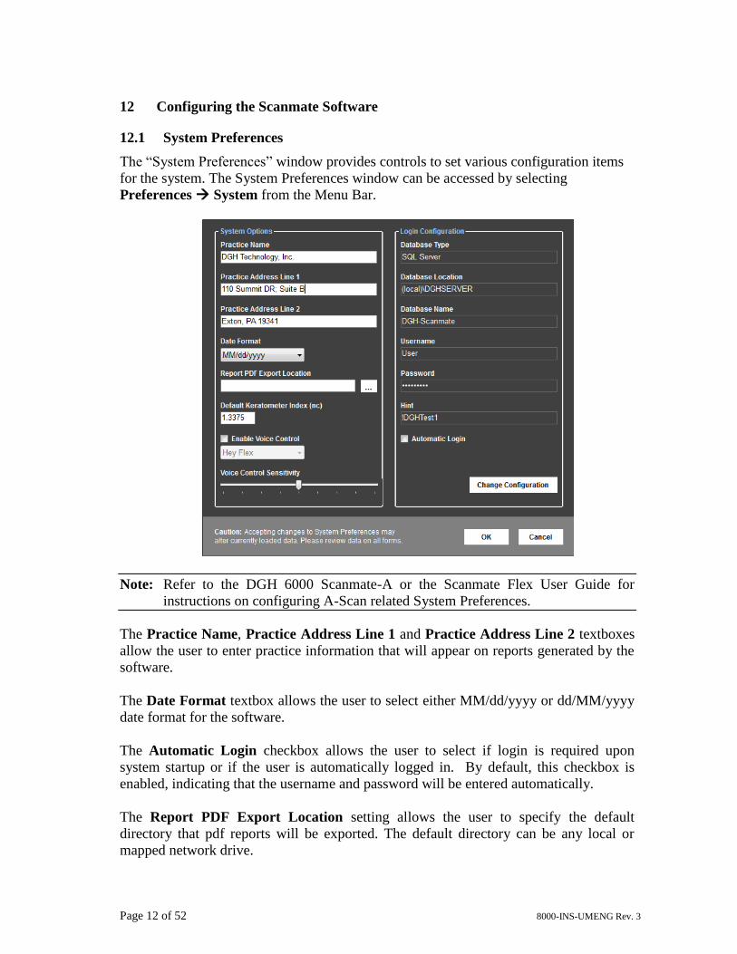
11.4 No USB Devices Detected Warning
If the USB probe is not attached, a warning box
will appear.
Clicking “OK” will complete the log-in and allow the Scanmate software to be used
without the USB probe. Although no scans can be completed, the software can still be
used to review B-Scan images, videos and reports.
If the Scanmate software is being used without the DGH 8000 probe attached, the
software will require probe key authentication before using, and after every 20 hours of
use. Warnings will appear every hour after 15 hours of use. To provide authentication,
plug a DGH 8000 probe into a USB port; authentication will complete in a few seconds.
11.5 Touch Controls
The Scanmate software can be operated using touch controls on systems that have a
touch-capable display. Buttons, sliders and combo boxes can be operated by touching
the screen. Measurement tools can be operated using touch controls (see Sections 15.11
through 15.14). Zooming and panning of zoomed images can also be controlled through
touch input (see Section 15.16).
Page 12 of 52 8000-INS-UMENG Rev. 3
12 Configuring the Scanmate Software
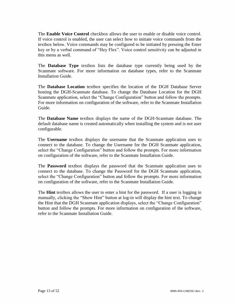
12.1 System Preferences
The “System Preferences” window provides controls to set various configuration items
for the system. The System Preferences window can be accessed by selecting
Preferences System from the Menu Bar.
Note: Refer to the DGH 6000 Scanmate-A or the Scanmate Flex User Guide for
instructions on configuring A-Scan related System Preferences.
The Practice Name, Practice Address Line 1 and Practice Address Line 2 textboxes
allow the user to enter practice information that will appear on reports generated by the
software.
The Date Format textbox allows the user to select either MM/dd/yyyy or dd/MM/yyyy
date format for the software.
The Automatic Login checkbox allows the user to select if login is required upon
system startup or if the user is automatically logged in. By default, this checkbox is
enabled, indicating that the username and password will be entered automatically.
The Report PDF Export Location setting allows the user to specify the default
directory that pdf reports will be exported. The default directory can be any local or
mapped network drive.
Page 13 of 52 8000-INS-UMENG Rev. 3
The Enable Voice Control checkbox allows the user to enable or disable voice control.
If voice control is enabled, the user can select how to initiate voice commands from the
textbox below. Voice commands may be configured to be initiated by pressing the Enter
key or by a verbal command of “Hey Flex”. Voice control sensitivity can be adjusted in
this menu as well.
The Database Type textbox lists the database type currently being used by the
Scanmate software. For more information on database types, refer to the Scanmate
Installation Guide.
The Database Location textbox specifies the location of the DGH Database Server
hosting the DGH-Scanmate database. To change the Database Location for the DGH
Scanmate application, select the “Change Configuration” button and follow the prompts.
For more information on configuration of the software, refer to the Scanmate Installation
Guide.
The Database Name textbox displays the name of the DGH-Scanmate database. The
default database name is created automatically when installing the system and is not user
configurable.
The Username textbox displays the username that the Scanmate application uses to
connect to the database. To change the Username for the DGH Scanmate application,
select the “Change Configuration” button and follow the prompts. For more information
on configuration of the software, refer to the Scanmate Installation Guide.
The Password textbox displays the password that the Scanmate application uses to
connect to the database. To change the Password for the DGH Scanmate application,
select the “Change Configuration” button and follow the prompts. For more information
on configuration of the software, refer to the Scanmate Installation Guide.
The Hint textbox allows the user to enter a hint for the password. If a user is logging in
manually, clicking the “Show Hint” button at log-in will display the hint text. To change
the Hint that the DGH Scanmate application displays, select the “Change Configuration”
button and follow the prompts. For more information on configuration of the software,
refer to the Scanmate Installation Guide.
Page 14 of 52 8000-INS-UMENG Rev. 3
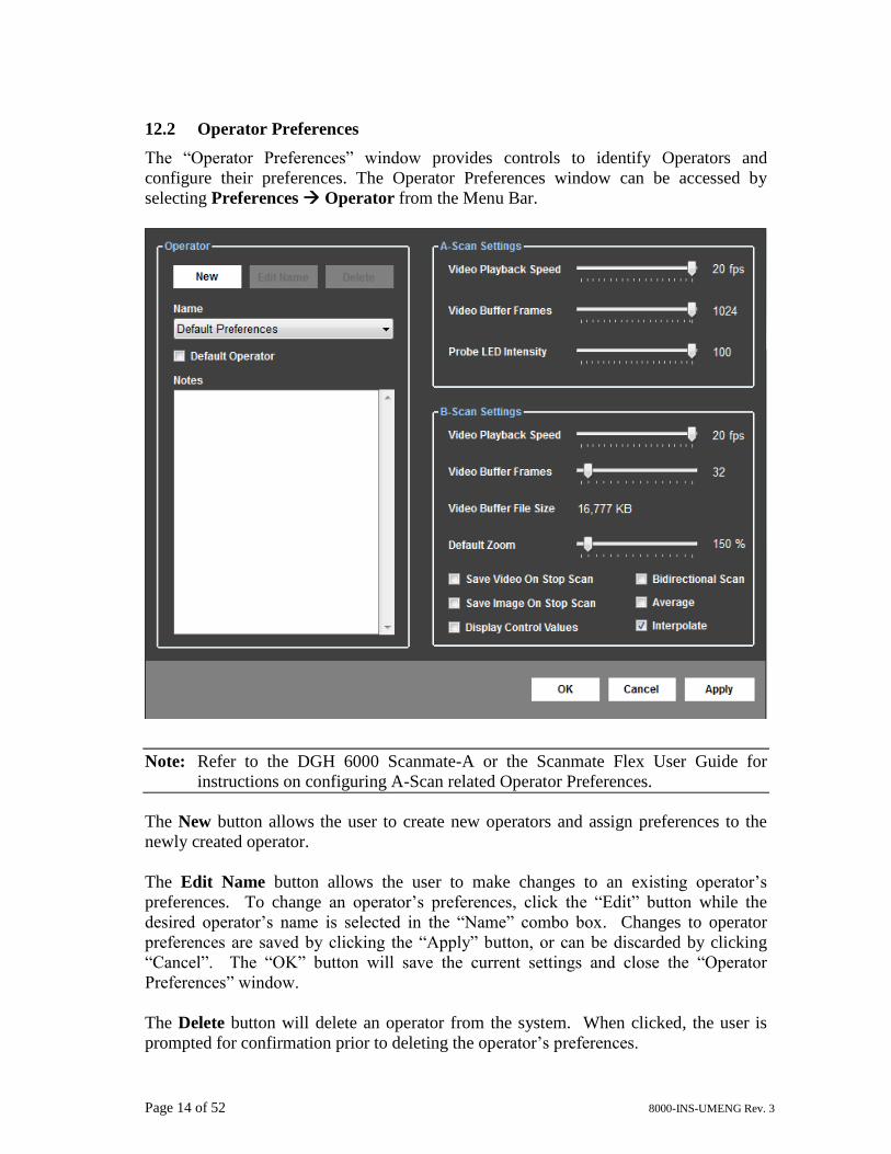
12.2 Operator Preferences
The “Operator Preferences” window provides controls to identify Operators and
configure their preferences. The Operator Preferences window can be accessed by
selecting Preferences Operator from the Menu Bar.
Note: Refer to the DGH 6000 Scanmate-A or the Scanmate Flex User Guide for
instructions on configuring A-Scan related Operator Preferences.
The New button allows the user to create new operators and assign preferences to the
newly created operator.
The Edit Name button allows the user to make changes to an existing operator’s
preferences. To change an operator’s preferences, click the “Edit” button while the
desired operator’s name is selected in the “Name” combo box. Changes to operator
preferences are saved by clicking the “Apply” button, or can be discarded by clicking
“Cancel”. The “OK” button will save the current settings and close the “Operator
Preferences” window.
The Delete button will delete an operator from the system. When clicked, the user is
prompted for confirmation prior to deleting the operator’s preferences.
Page 15 of 52 8000-INS-UMENG Rev. 3
The Name combo box selects an existing
operator from the database to view, edit, or
delete their preferences. Selecting an
operator’s name will display that operator’s
preferences on the screen. The Default
Operator checkbox selects which operator’s
preferences will be automatically loaded when the software is started.
The Notes textbox allows the user to
associate notes to an operator’s preferences.
The B-Scan Video Playback Speed slide bar
adjusts the frames per second (fps) that the B-
Scan video is played for the currently
selected operator. The speed of video
playback can be adjusted from 1 to 20 fps.
The B-Scan Video Buffer Frames slide bar
adjusts the size of the buffer used when
capturing B-Scan video. Moving the slide
bar from left to right increases the number of
frames stored in the buffer. Increasing the
number of frames that can be stored in the buffer allows the user to determine the
amount of video that is captured before it begins to overwrite itself. The video buffer
can be configured to store from 16 to 256 frames.
The B-Scan Default Zoom slide bar adjusts the amount of magnification applied to the
image or video when the zoom button is pressed.
When the Save Video On Stop Scan checkbox is selected, the B-Scan video will
automatically be saved when the scan is stopped.
When the Save Image On Stop Scan checkbox is selected, the last B-Scan frame will
automatically be saved when the scan is stopped.
The Display Control Values checkbox allows the user to select whether or not the
Gain, Intensity and Contrast control values are displayed in the B-Scan image window.
When the Bidirectional Scan checkbox is selected, the B-Scan probe will acquire image
information in both sweep directions.
Page 16 of 52 8000-INS-UMENG Rev. 3
The Average preference turns on the frame-to-frame B-Scan averaging algorithm. For
slower processors, averaging can be turned off to improve display performance at the
expense of image quality.
The Interpolate preference enables or disables the linear interpolation algorithm. For
slower processors, interpolation can be turned off to improve display performance at the
expense of image quality.
12.3 Doctor Preferences
The “Doctor Preferences” window provides controls for the user to identify Doctors and
configure their preferences. Doctor Preferences define the default protocol for
performing A-Scans and IOL Calculations. The Doctor Preferences window can be
accessed by selecting Preferences Doctor from the Menu Bar.
Note: Refer to the DGH 6000 Scanmate-A or the Scanmate Flex User Guide for
instructions on configuring A-Scan related Doctor Preferences.
The New button allows the user to create new doctor profiles and assign preferences to
the newly created doctor.
The Edit Name button allows the user to make changes to an existing doctor’s
preferences. The user can change a doctor’s preferences by clicking this button while
the desired doctor’s name is selected in the “Name” combo box.
The Delete button deletes a doctor from the system. When clicked, the user is prompted
for confirmation prior to deleting the doctor’s preferences. Once deleted, the doctor will
still exist in the database, but will be marked as inactive.
Page 17 of 52 8000-INS-UMENG Rev. 3
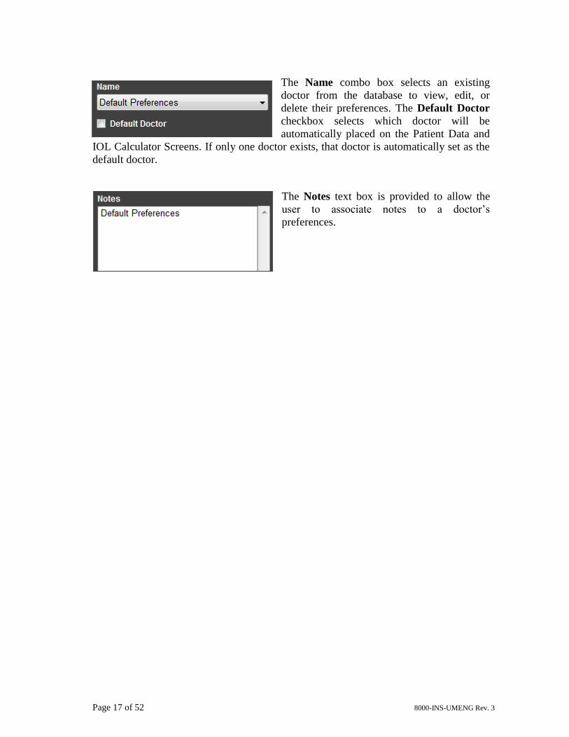
The Name combo box selects an existing
doctor from the database to view, edit, or
delete their preferences. The Default Doctor
checkbox selects which doctor will be
automatically placed on the Patient Data and
IOL Calculator Screens. If only one doctor exists, that doctor is automatically set as the
default doctor.
The Notes text box is provided to allow the
user to associate notes to a doctor’s
preferences.
Page 18 of 52 8000-INS-UMENG Rev. 3
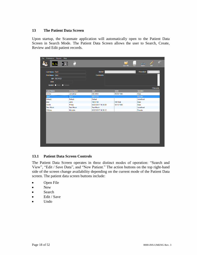
13 The Patient Data Screen
Upon startup, the Scanmate application will automatically open to the Patient Data
Screen in Search Mode. The Patient Data Screen allows the user to Search, Create,
Review and Edit patient records.
13.1 Patient Data Screen Controls
The Patient Data Screen operates in three distinct modes of operation: “Search and
View”, “Edit / Save Data”, and “New Patient.” The action buttons on the top right-hand
side of the screen change availability depending on the current mode of the Patient Data
screen. The patient data screen buttons include:
• Open File
• New
• Search
• Edit / Save
• Undo
Page 19 of 52 8000-INS-UMENG Rev. 3
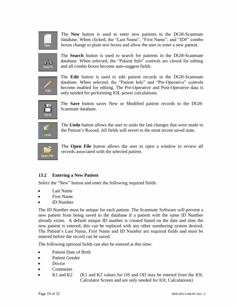
The New button is used to enter new patients in the DGH-Scanmate
database. When clicked, the “Last Name”, “First Name”, and “ID#” combo
boxes change to plain text boxes and allow the user to enter a new patient.
The Search button is used to search for patients in the DGH-Scanmate
database. When selected, the “Patient Info” controls are closed for editing
and all combo boxes become auto-suggest fields.
The Edit button is used to edit patient records in the DGH-Scanmate
database. When selected, the “Patient Info” and “Pre-Operative” controls
become enabled for editing. The Pre-Operative and Post-Operative data is
only needed for performing IOL power calculations.
The Save button saves New or Modified patient records to the DGH-
Scanmate database.
The Undo button allows the user to undo the last changes that were made to
the Patient’s Record. All fields will revert to the most recent saved state.
The Open File button allows the user to open a window to review all
records associated with the selected patient.
13.2 Entering a New Patient
Select the "New” button and enter the following required fields:
• Last Name
• First Name
• ID Number
The ID Number must be unique for each patient. The Scanmate Software will prevent a
new patient from being saved to the database if a patient with the same ID Number
already exists. A default unique ID number is created based on the date and time the
new patient is entered; this can be replaced with any other numbering system desired.
The Patient’s Last Name, First Name and ID Number are required fields and must be
entered before the record can be saved.
The following optional fields can also be entered at this time:
• Patient Date of Birth
• Patient Gender
• Doctor
• Comments
• K1 and K2 (K1 and K2 values for OS and OD may be entered from the IOL
Calculator Screen and are only needed for IOL Calculations)
Page 20 of 52 8000-INS-UMENG Rev. 3
• Desired Refraction (Desired Refraction for OS and OD may be entered from
the IOL Calculator Screen and are only needed for IOL
Calculations)
Select the Save button once all of the desired fields have been entered.
13.3 Searching for a Patient
Select the Search button to search for a patient record that has been saved in the
database. Patients can be searched for by Last Name, First Name, or by ID Number.
To search by Last Name, First Name or ID Number, begin typing in the field you wish
to search. The software will automatically update the patient table to show all the results
that match what has been typed. The desired patient can then be selected from this
patient list.
13.4 Editing a Patient Record
Select the desired patient record to be edited following the steps described in Section
13.3. Once the patient record has been loaded, select the Edit button. All of the editable
fields will change from read-only fields to white, editable text boxes. Once the desired
changes have been made, select the Save button to save the changed record.
Page 21 of 52 8000-INS-UMENG Rev. 3
14 The A-Scan Screen
The A-Scan Screen allows the user to perform and review A-Scan Measurements for the
currently selected patient. Refer to the DGH 6000 Scanmate-A or the Scanmate Flex
User Guide for instructions on using the A-Scan features of this program.
Page 22 of 52 8000-INS-UMENG Rev. 3
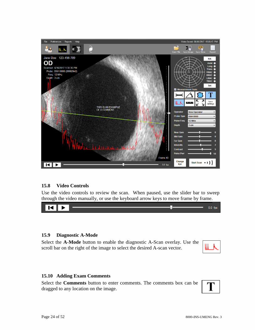
15 The B-Scan Screen
The B-Scan Screen allows the user to perform and review B-Scan exams for the
currently selected patient. Refer to Section 13 for details on how to load or create patient
records.
The default settings for this page are dependent on the currently selected Operator. The
default settings can be changed by selecting Preferences Operator.
15.1 Selecting the Probe
Select the desired probe from the list of
available probes in the Probe Type combo
box. The available Pulse Frequencies will be
displayed for the selected probe. The Depth
selection adjusts the depth of the displayed B-
Scan image.
Note: Pulse Frequency is the rate that the probe is electronically pulsed. It is not the
resonant frequency of the transducer crystal.
Page 23 of 52 8000-INS-UMENG Rev. 3
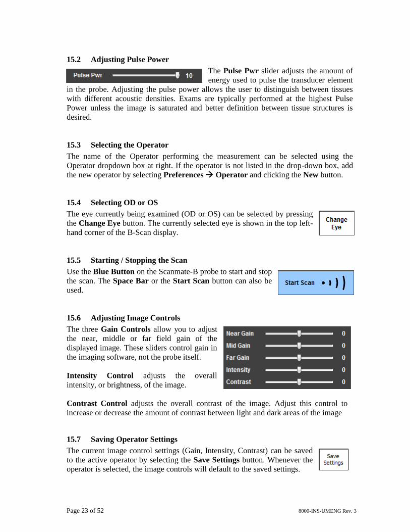
15.2 Adjusting Pulse Power
The Pulse Pwr slider adjusts the amount of
energy used to pulse the transducer element
in the probe. Adjusting the pulse power allows the user to distinguish between tissues
with different acoustic densities. Exams are typically performed at the highest Pulse
Power unless the image is saturated and better definition between tissue structures is
desired.
15.3 Selecting the Operator
The name of the Operator performing the measurement can be selected using the
Operator dropdown box at right. If the operator is not listed in the drop-down box, add
the new operator by selecting Preferences Operator and clicking the New button.
15.4 Selecting OD or OS
The eye currently being examined (OD or OS) can be selected by pressing
the Change Eye button. The currently selected eye is shown in the top left-
hand corner of the B-Scan display.
15.5 Starting / Stopping the Scan
Use the Blue Button on the Scanmate-B probe to start and stop
the scan. The Space Bar or the Start Scan button can also be
used.
15.6 Adjusting Image Controls
The three Gain Controls allow you to adjust
the near, middle or far field gain of the
displayed image. These sliders control gain in
the imaging software, not the probe itself.
Intensity Control adjusts the overall
intensity, or brightness, of the image.
Contrast Control adjusts the overall contrast of the image. Adjust this control to
increase or decrease the amount of contrast between light and dark areas of the image
15.7 Saving Operator Settings
The current image control settings (Gain, Intensity, Contrast) can be saved
to the active operator by selecting the Save Settings button. Whenever the
operator is selected, the image controls will default to the saved settings.
Page 24 of 52 8000-INS-UMENG Rev. 3
15.8 Video Controls
Use the video controls to review the scan. When paused, use the slider bar to sweep
through the video manually, or use the keyboard arrow keys to move frame by frame.
15.9 Diagnostic A-Mode
Select the A-Mode button to enable the diagnostic A-Scan overlay. Use the
scroll bar on the right of the image to select the desired A-scan vector.
15.10 Adding Exam Comments
Select the Comments button to enter comments. The comments box can be
dragged to any location on the image.
Page 25 of 52 8000-INS-UMENG Rev. 3
15.11 Measurement Tools
Mark the Measurement Tools check box to enable the use of
the Caliper Tool, Angle Tool and Area Tool.
Note: Measurement notations made with the Caliper Tool, Angle Tool and Area Tool
are only saved on still image records, not on videos.
15.12 Caliper Tool
Select the Caliper Tool button to take distance measurements. Left-click
hold and drag the mouse across the image. Additional measurement can be
added by clicking the button again and dragging additional caliper lines.
This can also be performed using touch controls.
The caliper measurement values are displayed near
the caliper line. Caliper lines can be adjusted and
moved by left-clicking the line and dragging the
control nodes to the desired position.
Caliper notations can be removed by right-clicking on the lines and selecting “Delete”
from the menu displayed or by left-clicking on the line to select it and pressing the
“Delete” keyboard key.
Page 26 of 52 8000-INS-UMENG Rev. 3
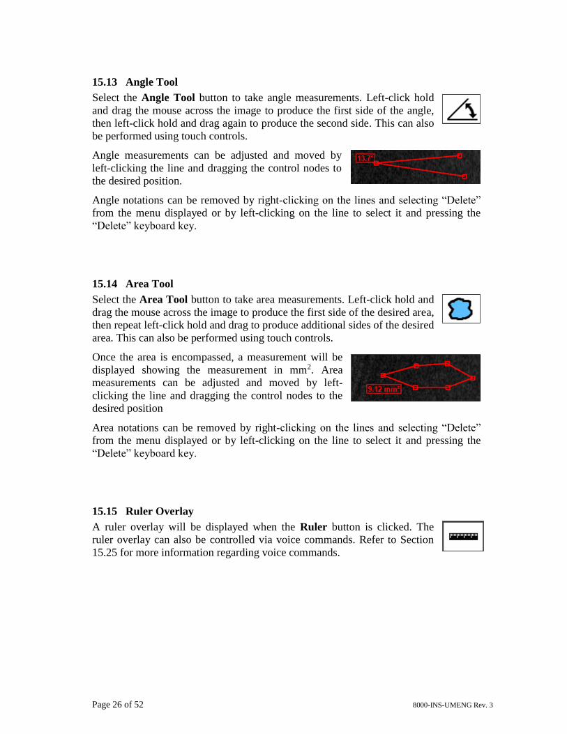
15.13 Angle Tool
Select the Angle Tool button to take angle measurements. Left-click hold
and drag the mouse across the image to produce the first side of the angle,
then left-click hold and drag again to produce the second side. This can also
be performed using touch controls.
Angle measurements can be adjusted and moved by
left-clicking the line and dragging the control nodes to
the desired position.
Angle notations can be removed by right-clicking on the lines and selecting “Delete”
from the menu displayed or by left-clicking on the line to select it and pressing the
“Delete” keyboard key.
15.14 Area Tool
Select the Area Tool button to take area measurements. Left-click hold and
drag the mouse across the image to produce the first side of the desired area,
then repeat left-click hold and drag to produce additional sides of the desired
area. This can also be performed using touch controls.
Once the area is encompassed, a measurement will be
displayed showing the measurement in mm2. Area
measurements can be adjusted and moved by left-
clicking the line and dragging the control nodes to the
desired position
Area notations can be removed by right-clicking on the lines and selecting “Delete”
from the menu displayed or by left-clicking on the line to select it and pressing the
“Delete” keyboard key.
15.15 Ruler Overlay
A ruler overlay will be displayed when the Ruler button is clicked. The
ruler overlay can also be controlled via voice commands. Refer to Section
15.25 for more information regarding voice commands.
Page 27 of 52 8000-INS-UMENG Rev. 3
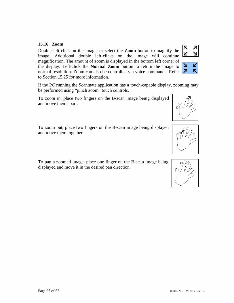
15.16 Zoom
Double left-click on the image, or select the Zoom button to magnify the
image. Additional double left-clicks on the image will continue
magnification. The amount of zoom is displayed in the bottom left corner of
the display. Left-click the Normal Zoom button to return the image to
normal resolution. Zoom can also be controlled via voice commands. Refer
to Section 15.25 for more information.
If the PC running the Scanmate application has a touch-capable display, zooming may
be performed using “pinch zoom” touch controls.
To zoom in, place two fingers on the B-scan image being displayed
and move them apart.
To zoom out, place two fingers on the B-scan image being displayed
and move them together.
To pan a zoomed image, place one finger on the B-scan image being
displayed and move it in the desired pan direction.
Page 28 of 52 8000-INS-UMENG Rev. 3
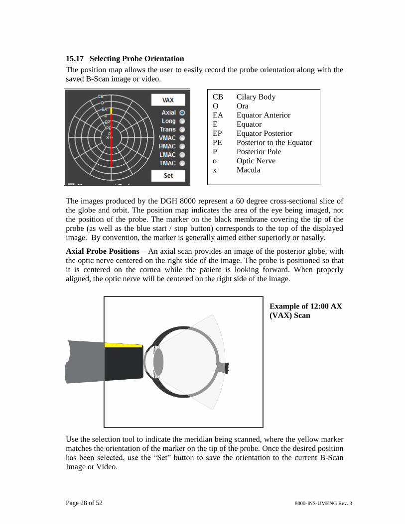
15.17 Selecting Probe Orientation
The position map allows the user to easily record the probe orientation along with the
saved B-Scan image or video.
The images produced by the DGH 8000 represent a 60 degree cross-sectional slice of
the globe and orbit. The position map indicates the area of the eye being imaged, not
the position of the probe. The marker on the black membrane covering the tip of the
probe (as well as the blue start / stop button) corresponds to the top of the displayed
image. By convention, the marker is generally aimed either superiorly or nasally.
Axial Probe Positions – An axial scan provides an image of the posterior globe, with
the optic nerve centered on the right side of the image. The probe is positioned so that
it is centered on the cornea while the patient is looking forward. When properly
aligned, the optic nerve will be centered on the right side of the image.
Example of 12:00 AX
(VAX) Scan
Use the selection tool to indicate the meridian being scanned, where the yellow marker
matches the orientation of the marker on the tip of the probe. Once the desired position
has been selected, use the “Set” button to save the orientation to the current B-Scan
Image or Video.
CB Cilary Body
O Ora
EA Equator Anterior
E Equator
EP Equator Posterior
PE Posterior to the Equator
P Posterior Pole
o Optic Nerve
x Macula
Page 29 of 52 8000-INS-UMENG Rev. 3
Longitudinal Probe Positions – Longitudinal scans provide a radial image from the
posterior pole to the anterior periphery. The probe is positioned on the sclera,
perpendicular to the limbus, while the patient is looking toward the area of the eye
being examined. The probe marker is pointed towards the limbus, causing the optic
nerve to be towards the bottom of the image.
Example of 12:00 L Scan
For a 12:00 Longitudinal scan, the marker on the tip of the probe is pointed toward the
area being examined at 12:00. The probe is positioned at 6:00, which is opposite of the
area being examined.
Use the selection tool to indicate the meridian being scanned. Once the desired
position has been selected, use the “Set” button to save the orientation to the current B-
Scan Image or Video.
Page 30 of 52 8000-INS-UMENG Rev. 3
Transverse Probe Positions – Transverse scans provide a lateral image of the globe
that traverses several clock hours. The position of the transverse scan is indicated by
the center of the clock hours in the scan as well as the portion of the globe being
examined (P for Posterior Pole, E for Equator, EA for Anterior to the Equator, etc.).
Example of 12:00 EP Scan
The probe is positioned on the sclera, parallel to the limbus, while the patient is
looking toward the area of the eye being examined. The probe marker is held parallel
to the limbus and pointed superiorly during vertical and oblique scans. For horizontal
scans (6:00 and 12:00 positions), the marker is pointed nasally to keep it parallel to the
limbus.
For a 12:00 EP scan, the probe is positioned at 6:00 with the marker parallel to the
limbus and pointed nasally. The probe is pointed toward the Equator Posterior at
12:00.
Use the selection tool to indicate the area of the globe being scanned. Once the desired
position has been selected, use the “Set” button to save the orientation to the current B-
Scan Image or Video.
Page 31 of 52 8000-INS-UMENG Rev. 3
Macula Scans
HMAC – A horizontal macula scan (HMAC) is a horizontal axial scan where the
probe has been aligned so that it is pointed directly at the macula. The marker on the
tip of the probe should be pointed nasally (3:00 OD or 9:00 OS). The optic nerve
shadow will be shifted towards the top of the display.
VMAC – A vertical macula scan (VMAC) is a vertical axial scan where the probe has
been aligned so that it is pointed directly at the macula. The marker on the tip of the
probe should be pointed in the superior (12:00) position.
LMAC – A longitudinal macula scan (LMAC) is a longitudinal scan through the
macula where the marker on the tip of the probe is pointed temporally (3:00 OS or
9:00 OD).
TMAC – A transverse macula scan (TMAC) is a vertical transverse scan where the
probe has been aligned so that it is pointed temporally (3:00 OS or 9:00 OD), directly
at the macula.
15.18 Saving B-Scan Images
B-Scan Images can be saved by selecting the Save Image Button on the
upper right-hand corner of the B-Scan Screen. This will also save all
changes that have been made to the Patient Data since the last save.
Alternatively, the currently loaded image can be saved using the toolbar at the top of the
screen by selecting File Save B-Scan Image.
15.19 Saving B-Scan Videos
B-Scan Videos can be saved by selecting the Save Video Button on the
upper right-hand corner of the B-Scan Screen. This will also save all
changes that have been made to the Patient Data since the last save.
Alternatively, the currently loaded video can be saved using the toolbar at the top of the
screen by selecting File Save B-Scan Video.
Page 32 of 52 8000-INS-UMENG Rev. 3
15.20 Reviewing B-Scan Exams
Saved B-scan files can be opened by clicking the Open File button. This
will open a window that shows all saved images and videos for the current
patient.
Double-clicking any image or video will open the file in
the scan view window.
The Push Pin allows the user to pin the scan view
window to the left-hand side of the Scanmate application
window so that both windows can be moved together.
Alternatively, the windows can be unpinned, so that they
can be moved independently.
The window can be configured to show saved records for
both eyes (OU) or to only show records for the right
(OD) or left (OS) eye.
Records can be deleted by Right-clicking and selecting
Delete from the context menu.
The Aspect Ratio of the window (vertical vs. horizontal)
can easily be changed.
Use the Check Box in the bottom right corner of each
thumbnail to include the image in the B-Scan Report.
15.21 Saving B-Scan Images as Jpegs
It is possible to convert saved B-Scan Files to .jpg images so that they can be shared
with EMR systems or practitioners that do not have the Scanmate Software. To do this,
select the Open File button on the B-Scan screen and drag the image thumbnail(s) to the
desired location.
Note: Jpeg files cannot be imported back into the Scanmate program. See Section 19
and 19.1 for other import / export options.
Page 33 of 52 8000-INS-UMENG Rev. 3
15.22 Saving B-Scan Videos as AVI Files
The Scanmate software can convert saved B-Scan videos to AVI files so that they can be
used outside of the Scanmate program.
To create an AVI file, first load a B-Scan video from the Scanmate database and select
File Export B-Scan Video (AVI).
Note: AVI files cannot be imported back into the Scanmate program. See Section 19
and 19.1 for other import / export options.
15.23 Creating Reports
Click the Report button to quickly create a B-scan report. The report will
include the patient information, doctor, operator, and date. A window with
all the saved images and videos for the current patient will open. Use the
checkboxes in the bottom right corner of each image to include them in the
report. The selected images will be shown inserted in a report preview window. Clicking
the Add Comments button in the report preview will open a comment box for text
entry. Reports can be sent to a printer, saved in the database, or saved as PDF files. For
more information on creating reports, see Section 17 “Creating Reports”.
Reports that had been saved to the database will be displayed in the window with patient
scans. PDF versions of reports can be exported by left-clicking and dragging them to the
desired location. Refer to Section 17.4 for more information.
Page 34 of 52 8000-INS-UMENG Rev. 3
15.24 Performing a B-Scan Exam
The ultrasound probe must be cleaned and disinfected before each biometry procedure.
(See Section 21 for Cleaning and Disinfection Instructions.)
Note: † Indicates a command that may be executed through B-Scan voice controls.
Refer to Section 15.25 for more information.
1. Launch the Scanmate Software Application as described in Section 11.
2. Select the “Patient Data” Page and either enter a new patient or select an existing
patient.
3. Navigate to the “B-Scan” page and select the eye to be examined (OD
or OS) by pressing the Change Eye† button.
4. Select the desired probe, frequency and depth from the drop-down box.
5. Select the name of the Operator performing the measurement. If the operator is not
listed in the “Operator” drop-down box, add the new operator by selecting
Preferences Operator and clicking the New button.
6. Seat or recline the patient in a comfortable position. Use a firm, comfortable head
rest to prevent unwanted head movement. Position the DGH Scanmate display so
that it is easily visible during the examination.
7. If desired, use the Position Map to indicate the area of the eye being examined.
8. Press the Blue Button† (on the probe) to begin scanning. Alternatively, clicking
the Start Scan button, the Space Bar (on the keyboard) or Left Foot Pedal
(optional accessory) will also begin a scan. The software will begin recording B-
Scan frames. The software will start recording over itself once the video buffer has
reached the “Video Buffer Frame Size” specified in the Operator Preferences.
9. Direct the patient to look in the desired direction and gently apply the probe
directly to the eye or over the eyelid. For best results, an acoustic coupling gel
(such as GenTeal) should be used.
10. Once the desired image has been obtained, press the Blue Button† (on the
probe), Stop Scan button, Space Bar (on the keyboard) or Left Foot Pedal
(optional accessory) to stop scanning.
11. The image frames captured during the exam can be reviewed on the display by
pressing the or cursor keys. The video playback controls can also be used to
play back the video of the exam. Alternatively, the slider below the B-Scan display
can be used to move through the video frame by frame.
12. Use the Gain, Intensity, Contrast and Zoom controls to enhance the quality of the
image. If desired, annotate the exam with comments or use the A-Mode, Area,
Angle and Caliper Tools.
Page 35 of 52 8000-INS-UMENG Rev. 3
13. Save the video (if desired) by selecting the Save Video† button. Individual
image(s) can also be saved by selecting the Save Image† button, pressing the
Enter keyboard key or by pressing the Right Foot Pedal (optional accessory).
Note: If the software is configured so that the Enter key initiates voice commands, an
image will not be saved when the Enter key is pressed.
14. Repeat the steps above until all the desired regions of the eye have been examined.
15. When the exam is complete, select the Report button to create a B-
scan report.
15.25 Voice Controls
Some controls can be operated via verbal commands from the user. Voice control can be
enabled/disabled through the Preferences System menu. Voice control can be
configured to begin upon pressing the “Enter” key or by a verbal command of “Hey
Flex”. Voice control sensitivity can be adjusted in this menu as well. The following
verbal commands are recognized by the Scanmate software while performing a B-Scan.
User Verbal
Commands
Software Audible
Response
Software Command
Executed
“Hey Flex” Tone: Double-Beep Voice control activated. The software is
ready to receive verbal commands.
“Start Scan” Verbal: “Starting Scan” The B-scan will start.
“Stop Scan” * Verbal: “Scan Stopped” The B-scan will stop.
“Change Eye” Verbal: “Eye changed to
OD/OS.”
The eye being scanned is changed. The
audible response will state if OD or OS is
being scanned.
“Zoom In” N/A Zoom will enlarge the image or video.
“Zoom Out” N/A Zoom will reduce the image or video.
“Show Ruler” N/A The ruler overlay is shown.
“Hide Ruler” N/A The ruler overlay is hidden.
“Save Image” Verbal: “Image Saved” The currently displayed frame is saved.
Page 36 of 52 8000-INS-UMENG Rev. 3
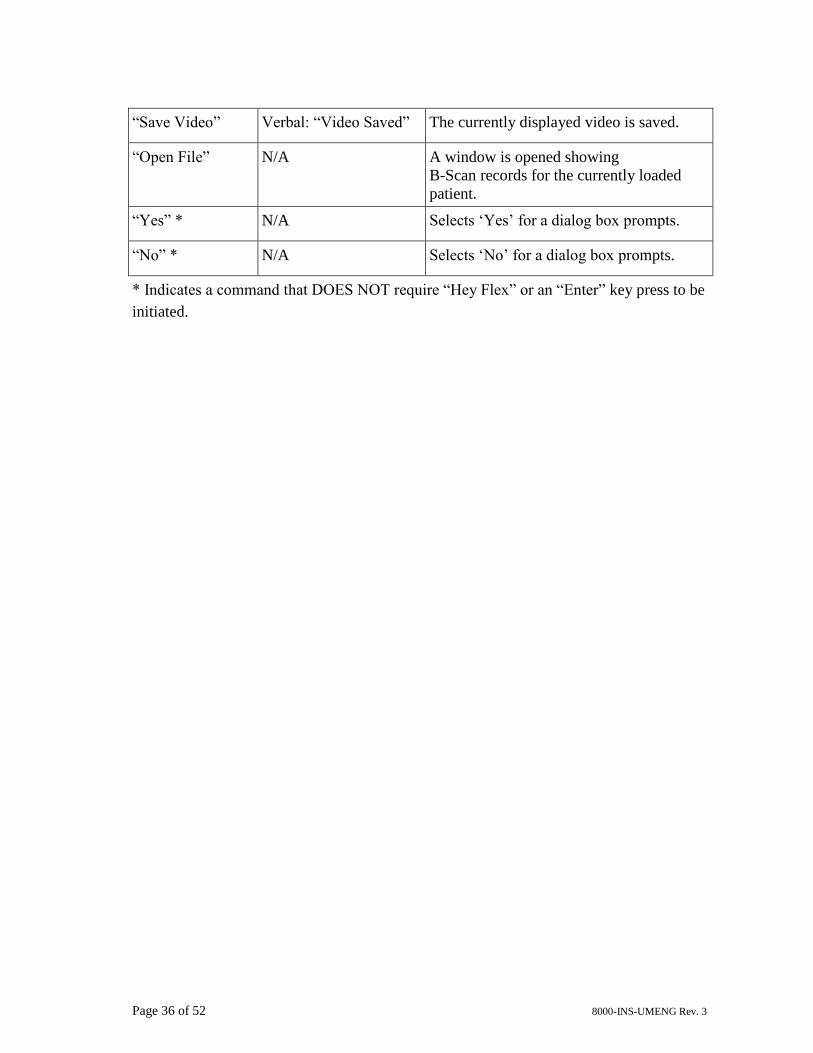
“Save Video” Verbal: “Video Saved” The currently displayed video is saved.
“Open File” N/A A window is opened showing
B-Scan records for the currently loaded
patient.
“Yes” * N/A Selects ‘Yes’ for a dialog box prompts.
“No” * N/A Selects ‘No’ for a dialog box prompts.
* Indicates a command that DOES NOT require “Hey Flex” or an “Enter” key press to be
initiated.
Page 37 of 52 8000-INS-UMENG Rev. 3
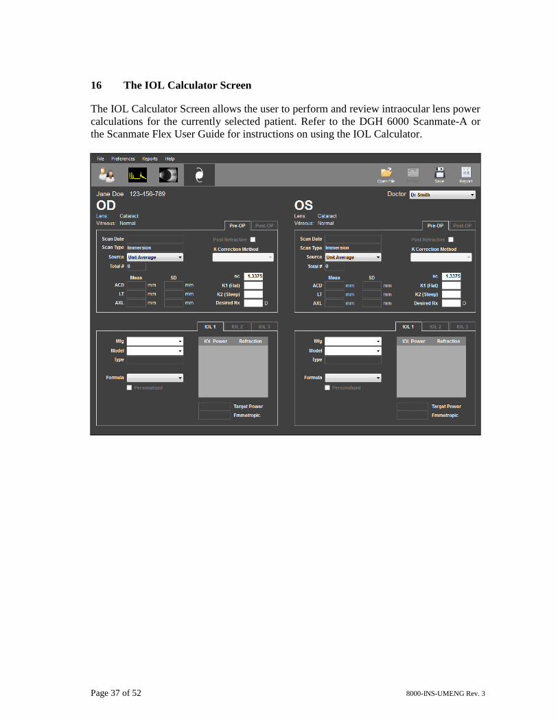
16 The IOL Calculator Screen
The IOL Calculator Screen allows the user to perform and review intraocular lens power
calculations for the currently selected patient. Refer to the DGH 6000 Scanmate-A or
the Scanmate Flex User Guide for instructions on using the IOL Calculator.
Page 38 of 52 8000-INS-UMENG Rev. 3
17 Creating Reports
Reports can be created for viewing from the Menu Bar. The DGH Scanmate software
can produce IOL Calculator Reports, A-Scan Short Reports, A-Scan Custom Reports
and B-Scan Reports. Reports can be printed out, saved as PDF files and added to the
patient record database. All reports are created with a header that includes the Patient’s
Name, ID Number, Doctor and Operator. The revision number of the DGH Scanmate
software used to generate the report is located in the footer of the report.
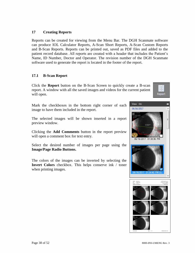
17.1 B-Scan Report
Click the Report button on the B-Scan Screen to quickly create a B-scan
report. A window with all the saved images and videos for the current patient
will open.
Mark the checkboxes in the bottom right corner of each
image to have them included in the report.
The selected images will be shown inserted in a report
preview window.
Clicking the Add Comments button in the report preview
will open a comment box for text entry.
Select the desired number of images per page using the
Image/Page Radio Buttons.
The colors of the images can be inverted by selecting the
Invert Colors checkbox. This helps conserve ink / toner
when printing images.
Page 39 of 52 8000-INS-UMENG Rev. 3
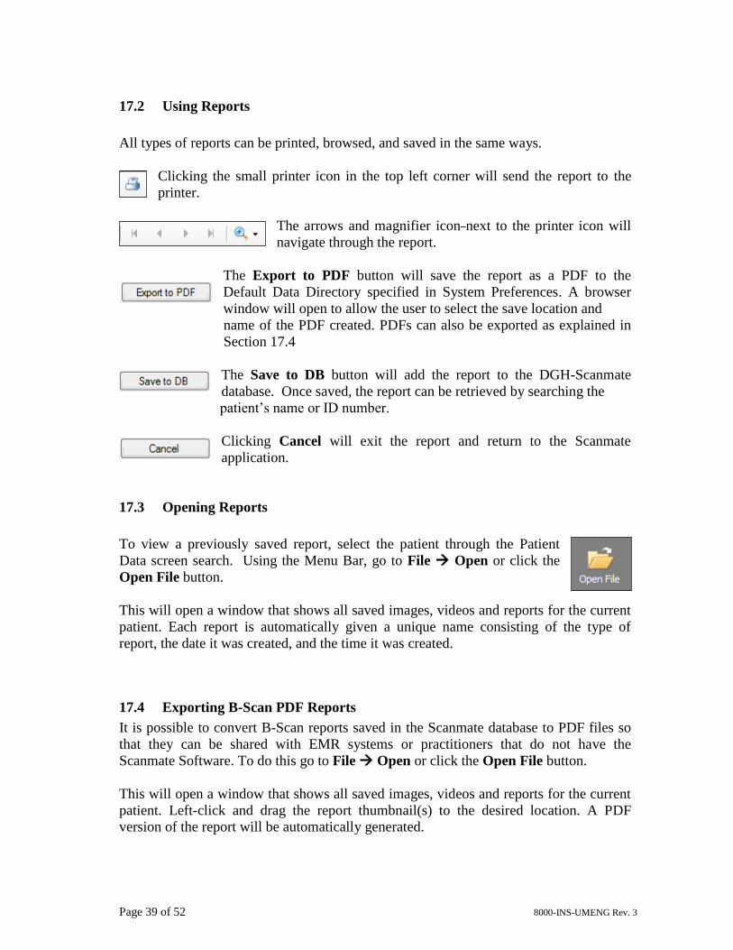
17.2 Using Reports
All types of reports can be printed, browsed, and saved in the same ways.
Clicking the small printer icon in the top left corner will send the report to the
printer.
The arrows and magnifier icon next to the printer icon will
navigate through the report.
The Export to PDF button will save the report as a PDF to the
Default Data Directory specified in System Preferences. A browser
window will open to allow the user to select the save location and
name of the PDF created. PDFs can also be exported as explained in
Section 17.4
The Save to DB button will add the report to the DGH-Scanmate
database. Once saved, the report can be retrieved by searching the
patient’s name or ID number.
Clicking Cancel will exit the report and return to the Scanmate
application.
17.3 Opening Reports
To view a previously saved report, select the patient through the Patient
Data screen search. Using the Menu Bar, go to File Open or click the
Open File button.
This will open a window that shows all saved images, videos and reports for the current
patient. Each report is automatically given a unique name consisting of the type of
report, the date it was created, and the time it was created.
17.4 Exporting B-Scan PDF Reports
It is possible to convert B-Scan reports saved in the Scanmate database to PDF files so
that they can be shared with EMR systems or practitioners that do not have the
Scanmate Software. To do this go to File Open or click the Open File button.
This will open a window that shows all saved images, videos and reports for the current
patient. Left-click and drag the report thumbnail(s) to the desired location. A PDF
version of the report will be automatically generated.
Page 40 of 52 8000-INS-UMENG Rev. 3
18 Database Management
Patient data, scan images, measurements, video files, and reports created by the
Scanmate application are saved in an DGH-Scanmate database. The database allows
patient records to be shared, centralized, or accessed remotely, according to the needs of
each biometry department. For example, several operators in a large practice could use
several Scanmate Flex, DGH 6000 or DGH 8000 units simultaneously, but all patient
records would be stored in a central database. Or, a doctor could perform scans in an
examination room, then later access patient records from an office computer.
Refer to the Scanmate Installation Guide for information on backing-up and restoring,
migrating, or deleting a database.
19 Importing and Exporting Data
B-Scan Image and Video files can be imported or exported from the DGH-Scanmate
database to be consulted in other locations or by other practitioners.
If both locations have the Scanmate Software (v3.0.0 or later) installed, the best way to
exchange B-Scan files is to use the .bscan file format. This format includes all the
necessary information to completely identify the patient and to re-create the record in
the database. It is also possible to export .jpg images or .avi movies to share with
practitioners that do not have the Scanmate Software. See Section 15.20 and 15.21 for
more details on exporting these file types.
To export a .bscan file, select File Export B-Scan File. The currently loaded B-
Scan Image or Video will be saved to the selected location.
To export a B-Scan video as a .avi file (which can be opened on most PC media
applications), select File Export B-Scan Video (AVI). The currently loaded B-
Scan Video will be saved to the selected location.
To import a .bscan file, select File Import B-Scan File. A browser window will
open to select a .bscan file to open. Once opened, the file will load the Patient Data and
B-Scan information into the Scanmate program. The opened file can be saved in the
database at this point.
Page 41 of 52 8000-INS-UMENG Rev. 3
19.1 Importing Legacy Files (.bs or .cini)
It is possible to import .bs and .cini files from prior versions of the Scanmate-B
software. To import a .bs or .cini file, select File Import B-Scan File.
A browser window will open to select a .bs or .cini file to open. Because these files do
not contain all the necessary information to be included in the DGH-Scanmate database,
a dialog window will open requesting additional information when importing these file
types.
Select the Patient that you would like to associate the imported file with. If the desired
patient is not shown, select Cancel and add the patient to the database. Verify that the
Eye (OD or OS) and the Scan Date are correct and select Import.
Once opened, the file will load the Patient Data and B-Scan information into the
Scanmate program. The opened file can be saved in the database at this point.
Page 42 of 52 8000-INS-UMENG Rev. 3
20 Electromagnetic Compatibility
Like other medical equipment, the DGH 8000 Scanmate-B requires special precautions
to ensure electromagnetic compatibility with other electrical medical devices. To ensure
electromagnetic compatibility (EMC), the DGH 8000 must be installed and operated
according to the EMC information provided in this manual.
The DGH 8000 has been designed and tested to comply with EN 60601-1-2
requirements for EMC with other devices.
Guidance and Manufacturer’s Declaration: Electromagnetic Emissions & Immunity
The DGH 8000 Probe is intended for use in the electromagnetic environment specified below. The customer
or the user of the USB Ultrasound Probe should ensure that it is used in such an environment.
Environmental
Phenomena
Test In
Accordance to
Level Criteria Basic
Standard
Notes
Radiated
Emissions
EN60601-1-2 Group 1
Class a
Under
Limit
CISPR 11 Measure at 5 meters
Electrostatic
Discharge
EN60601-1-2 ±2Kv ±4Kv ±8Kv
contact discharge
±2Kv ±4Kv ±8Kv
air discharge
36.202.1 (j) EN61000-4-2 Apply to all accessible
components
Radiated
Immunity
EN60601-1-2 80MHz-2.5GHz
3V/m 80%@1kHz
36.202.1 (j) EN61000-4-3 Expose all parts of EUT to
field
EFT
I/O Only
EN60601-1-2 ±2Kv
5/50 5kHz
36.202.1 (j) EN61000-4-4 None
Conducted
Immunity
I/O Only
EN60601-1-2 0.15 – 80MHz
3Vrms
80%@1kHz
36.202.1 (j) EN61000-4-6 None
! CAUTION
Portable and mobile RF communications equipment may affect the normal
function of the DGH 8000 Scanmate-B.
! CAUTION
Do not use cables or accessories other than those provided with the DGH 8000
Scanmate-B, as they may result in increased electromagnetic emissions or
decrease immunity to such emissions.
Page 43 of 52 8000-INS-UMENG Rev. 3
Guidance and Manufacturer’s Declaration: Electromagnetic Immunity
The DGH 8000 Scanmate-B is intended for use in the electro-magnetic environment
specified below. The customer or the user of the DGH 8000 should ensure that it is used
in such an environment.
Field strength from fixed transmitters, such as base stations for radio (cellular/cordless)
telephones and land mobile radios, armature radio, AM and FM radio broadcast and TV
broadcast, cannot be predicted theoretically with accuracy. To assess the electromagnetic
environment due to fixed RF transmitters, an electromagnetic site survey should be
considered. If the measured field strength in the location in which the DGH 8000 is used
exceeds the applicable RF compliance level, the DGH 8000 should be observed to verify
normal operation. If abnormal performance is observed, additional measures may be
necessary, such as reorienting or relocating the DGH 8000.
21 Cleaning and Disinfection
! WARNING
Users of the DGH 8000 Scanmate-B have an obligation and responsibility to
provide the highest degree of infection control possible to patients, co-workers
and themselves. To avoid cross contamination, follow all infection control
policies established for the office, department or hospital as they apply to
personnel and equipment.
! WARNING
Always disconnect the DGH 8000 from the host computer before performing
maintenance or cleaning.
Always follow the manufacturer’s instructions when cleaning and disinfecting
probes.
Do not use a surgeon’s brush when cleaning probes. Even the use of soft brushes
can damage the probe.
Page 44 of 52 8000-INS-UMENG Rev. 3
21.1 Probe Cleaning
1. Wear protective gloves when performing the cleaning process.
2. Disconnect the probe from the system.
3. Use a soft cloth lightly dampened in a mild soap or compatible cleaning solution
to remove any particulate matter or body fluids that remain on the probe or cable.
4. To remove remaining particulates, rinse with water up to the blue strain relief
where the USB cable enters the probe. Do not immerse the strain relief or USB
cable.
5. Wipe with a dry cloth; or wipe with a water-dampened cloth to remove soap
residue, and then wipe with a dry cloth.
21.2 Probe Disinfection
The following disinfectants are recommended due to their biological effectiveness as
well as their chemical compatibility with the DGH 8000 materials.
1. Wear protective gloves when performing the disinfecting procedure.
2. Check the expiration date on the solution that is being used. Use only solutions
that are within the expiration date.
3. Mix the disinfection solution compatible with the probe according to label
instructions for solution strength. A disinfectant qualified by the FDA 510(k)
process is recommended.
4. Immerse the tip of the probe approximately 1.5 cm in the disinfection solution.
Avoid immersion beyond the membrane / probe interface.
5. Follow the instructions on the disinfection label for the duration of probe
immersion.
6. Using the instructions on the disinfectant or sterilization label, rinse the probe up
to the point of immersion, and then air dry or towel dry with a clean cloth.
7. Examine the probe for damage such as cracks, splitting, fluid leaks, or sharp
edges or projections. If damage is evident, discontinue use of the probe and
contact a customer service representative.
Solutions Country Type Active ingredient FDA 510(k)
Cidex® USA Liquid Gluteraldehyde K934434
Cidex Plus® USA Liquid Gluteraldehyde K923744
Page 45 of 52 8000-INS-UMENG Rev. 3
! WARNING
DGH makes no claims about the biological effectiveness as a disinfectant of any
of the products listed above. Furthermore, DGH makes no claims regarding the
effectiveness of any of these products for killing any known, or unknown,
bacteria, virus, or other micro-organisms. DGH only claims that these products,
when used properly, will not harm the probe tip.
! WARNING
Using a non-recommended disinfectant, incorrect solution strength, or immersing
the probe tip deeper than described in step #4 (above), or for a period longer than
recommended can damage or discolor the probe and will void the probe warranty.
Do not immerse the probe tip for longer than one hour. The probe may be
damaged by longer immersion times.
Disinfect the probe tip using only the liquid solutions. Using autoclave, gas
(EtO), or other non DGH Technology approved methods will damage the probe
and void the warranty.
! WARNING
It is the responsibility of the user to remain current with the latest information
from the relevant disinfectant manufacturer concerning instructions, effects,
necessary concentrations, immersion times and rinse requirements.
Page 46 of 52 8000-INS-UMENG Rev. 3
22 Care and Maintenance
22.1 Care of the USB Probe
The USB probe is a completely sealed unit. The probe may be submersed in water up to
the cable during normal use.
The probe should be cleaned after every use. See the “Cleaning and Disinfecting”
section for more details.
Regularly check the front face of the probe for cracks, as this may cause a loss of fluid,
which would impair the performance of the probe.
Be sure to keep the USB connector dry at all times.
Regularly check the USB cables for cuts cracks and kinks. The presence of these defects
can impair the performance of the device.
22.2 Maintenance of the USB Probe
Periodic testing and maintenance of the USB Ultrasound Probe is NOT required.
22.3 Operating Conditions
The DGH 8000 (Scanmate-B) should be operated within the following conditions:
• Max operating temperature 40°C (104°F)
• Min operating temperature 10 °C (50 °F)
• Operating humidity range 20 - 80% non-condensing
! WARNING
Do Not Attempt To Open the Probe Housing
! WARNING
Do Not Attempt to Disconnect or Remove USB Cable from the Probe
Page 47 of 52 8000-INS-UMENG Rev. 3
22.4 Storage
When the DGH 8000 is not being used, it should be stored in a clean, dry area.
To prevent damage to the DGH 8000, do not store in areas where it might be exposed to:
• Excessive vibration
• Excessive dust and dirt
• Liquids or condensation
• Impact
Store the DGH 8000 under the following ambient conditions:
• Temperature: -10°C to 50C° (14°F to 122°F)
• Relative Humidity: 20% to 80% (no condensation)
• Atmospheric pressure: 70 kPa to 106 kPa
22.5 Transportation
Never carry the DGH 8000 by the USB cable.
Never bend the USB cable in a tight radius. This could result in damage to the cable.
Transport the DGH 8000 under the following ambient conditions:
• Temperature: -10°C to 50C° (14°F to 122°F)
• Relative Humidity: 20% to 80% (no condensation)
• Atmospheric pressure: 70 kPa to 106 kPa
When transporting the DGH 8000 to a different field location or when returning it for
repair or maintenance, use the original DGH 8000 packing enclosure.
If the original package is not available, pack in such a way that the DGH 8000 is
protected.
22.6 Disposal
Contact DGH Technology, Inc. before disposing of the DGH 8000.
Concerning the WEEE label, the following information is for EU member states:
The use of this symbol indicates that this product should not be treated as household
waste. By ensuring that this product is disposed of correctly, you will help prevent
potential negative consequences for the environment and human health, which could
otherwise be caused by inappropriate waste-handling of this product. For more
information concerning the return and recycling of this product, please consult DGH
Technology, Inc.
Page 48 of 52 8000-INS-UMENG Rev. 3
23 Troubleshooting
Refer to the Scanmate Installation Guide for troubleshooting instructions related to the
installation and configuration of the Scanmate software. The installation guide also
contains information on backing up, restoring and moving the patient database.
24 Warranty
DGH Technology, Inc. “DGH” warrants each new DGH 8000 and its accompanying
accessories (hereinafter called “Equipment”) to be free from defects in material and
workmanship for twelve (12) months from the date of delivery to the original purchaser.
This warranty is not applicable to any defect that is the result of an accident, misuse,
mishandling, neglect, improper installation, improper repair or improper modification by
persons other than DGH. This warranty does not apply if the Equipment has not been
operated and maintained in accordance with the operating and maintenance manuals and
instructions or bulletins issued in respect thereof by DGH. The cost of servicing
replaceable and expendable items including parts and labor made in connection with the
routine maintenance services as described in such Operator’s Manual is not covered
under this warranty and is the responsibility of the purchaser.
This warranty is strictly limited to replacement or repair of the part that is found to be
defective in material and workmanship. At the option of DGH, said part shall be
replaced or repaired free of charge, F.O.B. our factory by DGH.
DGH reserves the right to make changes in the design and material of Equipment
without incurring any obligations to incorporate such changes in Equipment already
completed on the effective date of any such changes.
This is the only warranty of this product and is expressly in lieu of all other warranties,
expressed or implied by law or otherwise, including any implied warranties of
merchantability and of fitness for a particular purpose. Without regard to the alleged
defect, DGH does not, under any circumstances, assume any responsibility for the loss
of time, inconvenience or other consequential damages, including but not limited to, loss
or damage of personal property, or loss of revenue. DGH has neither assumed nor
authorized any other person (including any distributor authorized to sell its Equipment)
to assume for it any other liability in the connection with the sale of Equipment.
25 Lifetime / Shelf-life
The shelf-life / lifetime indicated for this device is 5 years.
Page 49 of 52 8000-INS-UMENG Rev. 3
26 Customer Service
If you are having problems with this unit, please refer to the appropriate sections of this
manual. Most service calls result from a misinterpretation of the operation of the
instrument. The instructions in this manual have been carefully reviewed to ensure error-
free performance of the DGH 8000.
However, if you feel there is a problem with the unit or a transducer, please contact the
Customer Service Department at the address below. DGH Technology, Inc. can also be
contacted via our website at www.dghtechnology.com. When contacting us, please
provide the model and serial number for the unit. The model number and serial number
are located on the side of the USB probe and can also be viewed on the display by
selecting the “About” button found on the “Help” toolbar.
Manufactured by:
Authorized European Representative:
Molenstraat 15
2513 BH, The HagueThe NetherlandsPhone: +31.70.345.8570
EC REP
EMERGO EUROPEDGH TECHNOLOGY, INC.110 SUMMIT DRIVESUITE B
EXTON, PA 19341USA (610) 594-9100
Molenstraat 15
2513 BH, The HagueThe NetherlandsPhone: +31.70.345.8570
EC REP
EMERGO EUROPEDGH TECHNOLOGY, INC.110 SUMMIT DRIVESUITE B
EXTON, PA 19341USA (610) 594-9100
Prinsessegracht 20 2514 AP, The Hague The Netherlands
Molenstraat 15
2513 BH, The HagueThe NetherlandsPhone: +31.70.345.8570
EC REP
EMERGO EUROPEDGH TECHNOLOGY, INC.110 SUMMIT DRIVESUITE B
EXTON, PA 19341USA (610) 594-9100
Page 50 of 52 8000-INS-UMENG Rev. 3
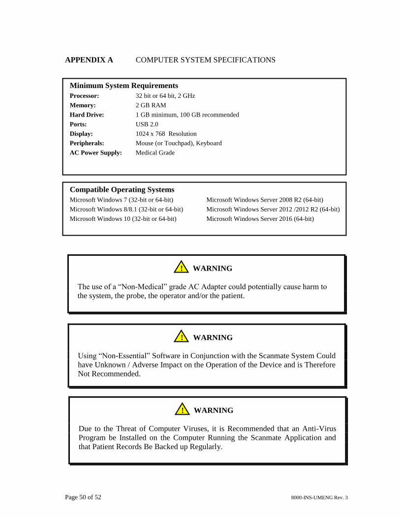
APPENDIX A COMPUTER SYSTEM SPECIFICATIONS
! WARNING
Using “Non-Essential” Software in Conjunction with the Scanmate System Could
have Unknown / Adverse Impact on the Operation of the Device and is Therefore
Not Recommended.
! WARNING
The use of a “Non-Medical” grade AC Adapter could potentially cause harm to
the system, the probe, the operator and/or the patient.
! WARNING
Due to the Threat of Computer Viruses, it is Recommended that an Anti-Virus
Program be Installed on the Computer Running the Scanmate Application and
that Patient Records Be Backed up Regularly.
Minimum System Requirements
Processor: 32 bit or 64 bit, 2 GHz
Memory: 2 GB RAM
Hard Drive: 1 GB minimum, 100 GB recommended
Ports: USB 2.0
Display: 1024 x 768 Resolution
Peripherals: Mouse (or Touchpad), Keyboard
AC Power Supply: Medical Grade
Compatible Operating Systems
Microsoft Windows 7 (32-bit or 64-bit) Microsoft Windows Server 2008 R2 (64-bit)
Microsoft Windows 8/8.1 (32-bit or 64-bit) Microsoft Windows Server 2012 /2012 R2 (64-bit)
Microsoft Windows 10 (32-bit or 64-bit) Microsoft Windows Server 2016 (64-bit)
Page 51 of 52 8000-INS-UMENG Rev. 3
APPENDIX B SUMMARY OF ACOUSTIC OUTPUT (12.0 MHz Probe)


![DGH Shale Gas[1]](https://static.documents.pub/doc/80x56/547775a5b4af9f87108b47f1/dgh-shale-gas1.jpg)


