1 DHANALAKSHMI COLLEGE OF ENGINEERING Dr.V.P.R NAGAR CHENNAI-601301 LABORATORY MANUAL Name : ……………………………………… Register No. : ……………………………………… Branch : ……………………………………… Year & Semester : ……………………………………… ME6513 - METROLOGY AND MEASUREMENT LAB Department of Mechanical Engineering
Transcript
1
DHANALAKSHMI COLLEGE OF ENGINEERING
Dr.V.P.R NAGAR CHENNAI-601301
LABORATORY MANUAL
Name : ………………………………………
Register No. : ………………………………………
Branch : ………………………………………
Year & Semester : ………………………………………
ME6513 - METROLOGY AND MEASUREMENT LAB
Department of Mechanical Engineering
2
3
CONTENTS
S.NO.
DATE EXPERIMENT NAME PAGE
NO.
SIGNATURE
1 Calibration of outside micrometer
2 Calibration of vernier height gauge
3 Mechanical Comparator
4 Calibration of vernier caliper
5 Angle of taper rod using sine bar
6 Angle of taper rod using sine center
7 Angle of V-block optical bevel
protector
8 Measurement of spur gear tooth
dimensions
9 Vibration Set up
10 Displacement using strain gauge
11 Measurement of screw thread using
profile projector
12 Vibration set up
13 Measurement of straightness and
flatness using auto collimators
14 Force measurement
15 Temperature measurement
16 Tool maker microscope
4
Ex No:
CALIBRATION OF OUTSIDE MICROMETER
Date :
Aim:
To calibrate the outside micrometer using slip gauge
Instruments Required:
1. Micrometer stand
2. outside Micrometer
3. Slip gauge
Specifications:
1. Outside micrometer
Range =0 - 25mm
Graduations=0.01mm
Description:
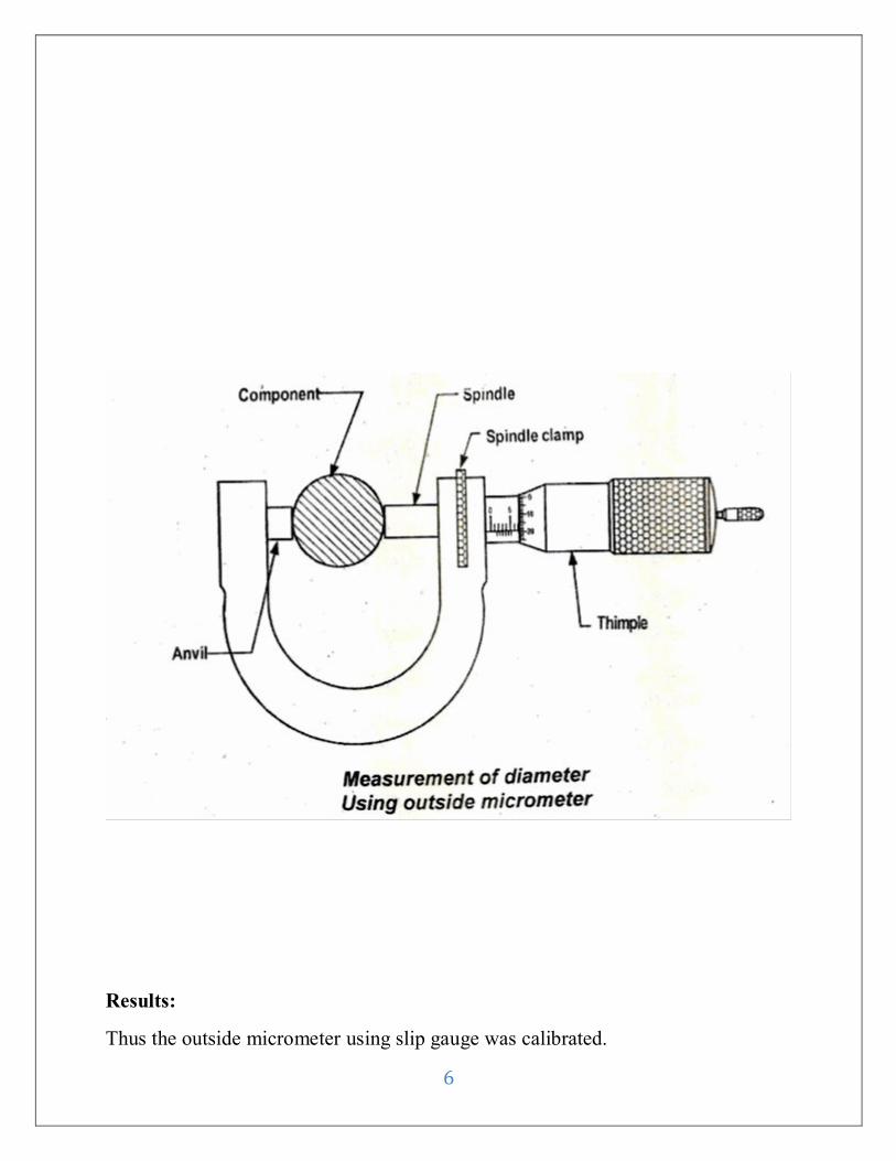
Outside Micrometer
It is used for checking the thickness of the square Rectangular and circular
round balls. It is consists of various parts such as anvil spindle frame thimble
ratchet.
Procedure:
1. The micrometer is checked for zero error.
2. The given slip gauge is held between the faces of the anvil and spindle.
3. The spindle is moved by rotating the thimble until the anvil and spindle
touches the surface of the component.
4. Fine adjustment is made by ratchet. The main scale reading and thimble
scale reading are noted.
5. Two are more reading are taken at different places of the component.
6. The readings are tabulated and calculated.
5
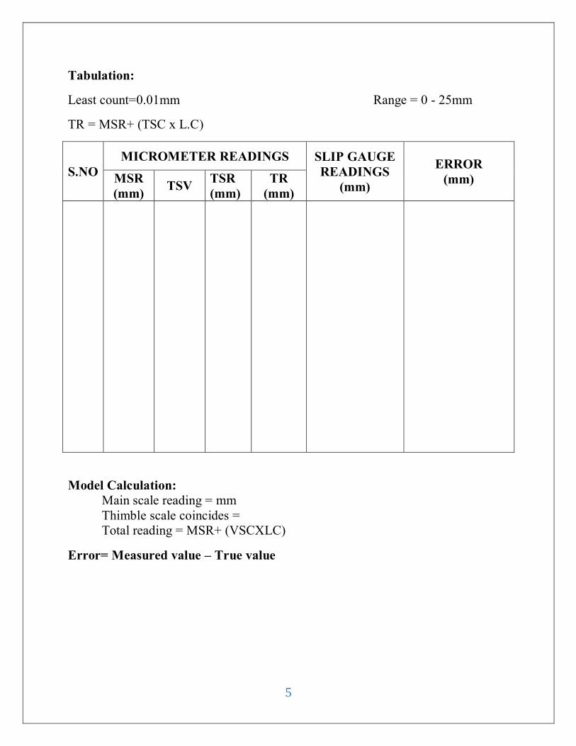
Tabulation:
Least count=0.01mm Range = 0 - 25mm
TR = MSR+ (TSC x L.C)
S.NO
MICROMETER READINGS SLIP GAUGE
READINGS
(mm)
ERROR
(mm) MSR
(mm) TSV
TSR
(mm)
TR
(mm)
Model Calculation:
Main scale reading = mm
Thimble scale coincides =
Total reading = MSR+ (VSCXLC)
Error= Measured value – True value
6
Results:
Thus the outside micrometer using slip gauge was calibrated.
7
Ex No:
CALIBRATION OF VERNIER HEIGHT GAUGE USING SLIP GAUGE
Date :
Aim:
To calculate the Vernier height gauge using slip gauges
Instruments Required
1. Vernier height gauge
2. Slip gauge
Formula Used:
TR = MSR+ (VSCXLC)
Where, TR-Total Reading
MSR-Main Scale Reading
VSC-Vernier Scale Coincide
LC-Least Count
Description:
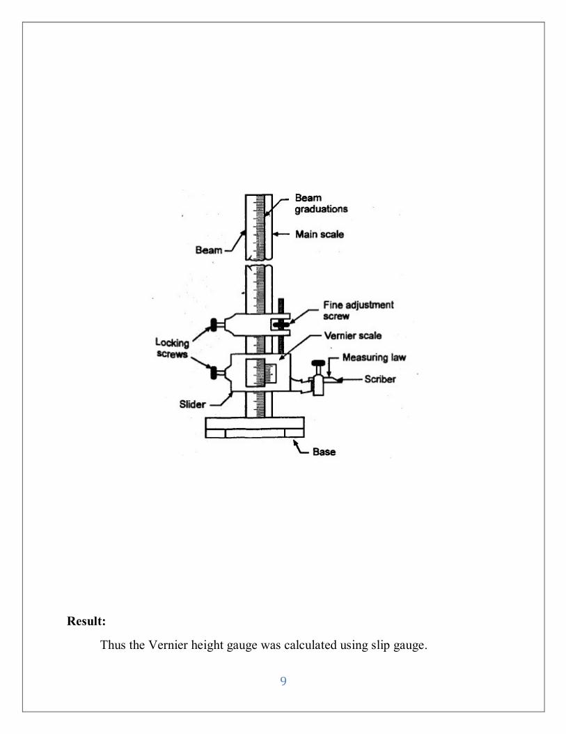
Vernier height gauge consists of a special base block and other attachment
.The whole assembly is made such a way to measure height of parts to be
measured. A removable clamp is attached b/w measuring jaws and Vernier both
the upper and lower end of measuring jaws and Vernier are parallel to the base of
Vernier height gauge. A scribing attachment is fitted to mark scribe line on the
parts where is required sometimes measuring jaws of Vernier caliper are replaced
by a dial gauge according to the type of measurement.
Procedure:
Vernier height gauge is cleaned with a cloth.
The clamping screws are loosened.
The given component is fixed in both the two jaws.
The component should be perfectly holded.
The height is measured with the external jaws.
The height of the component is measured by adjusting the movable jaws.
8
The procedure is repeated for all the components.
At least three readings should be taken and then average will give the
accurate measurement.
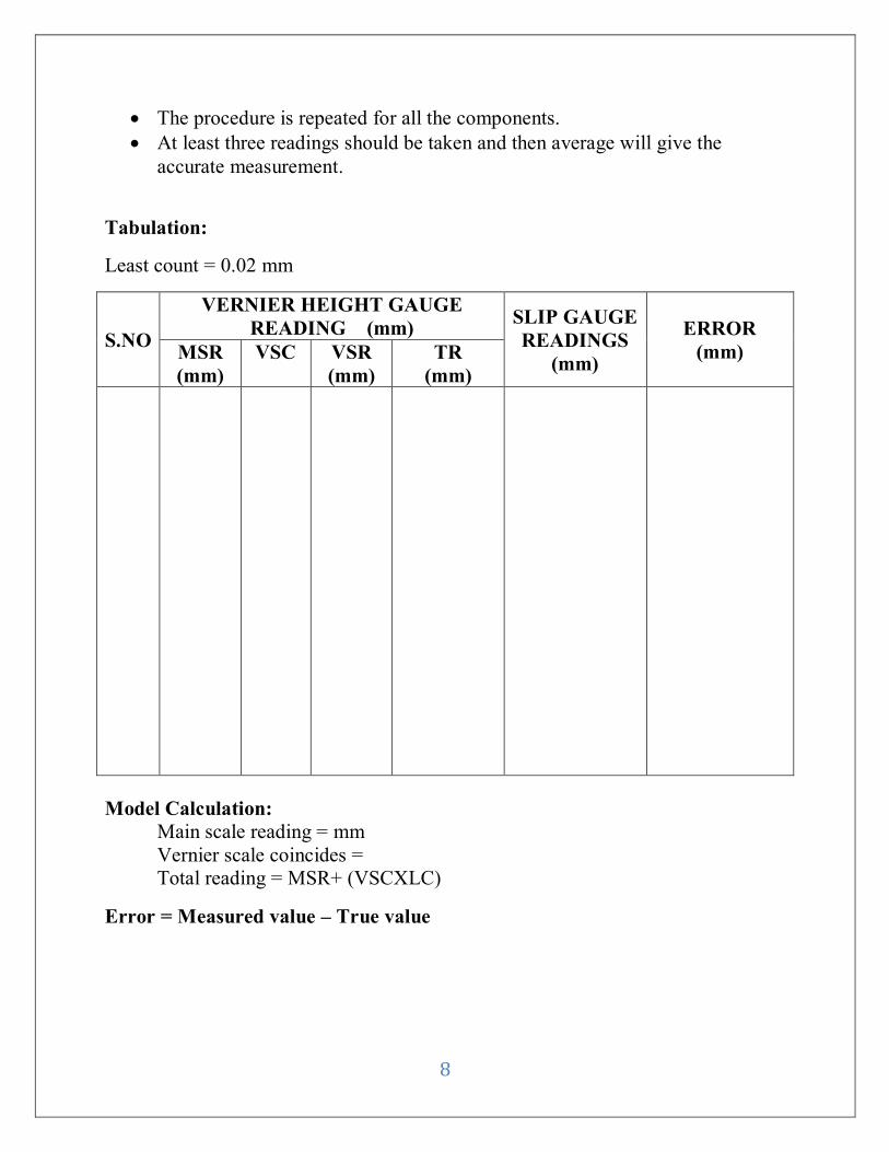
Tabulation:
Least count = 0.02 mm
S.NO
VERNIER HEIGHT GAUGE
READING (mm) SLIP GAUGE
READINGS
(mm)
ERROR
(mm) MSR
(mm)
VSC VSR
(mm)
TR
(mm)
Model Calculation:
Main scale reading = mm
Vernier scale coincides =
Total reading = MSR+ (VSCXLC)
Error = Measured value – True value
9
Result:
Thus the Vernier height gauge was calculated using slip gauge.
10
Ex No:
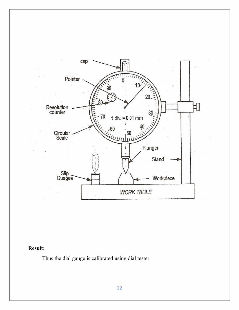
CALIBRATION OF DIAL GAUGE
Date :
Aim:
To calibrate the dial gauge by using dial tester
Instruments Required:
1. Dial gauge
2. Dial tester
Description:
Dial test indicator are used for checking surface of parallelism of rods and
bars. They are also used for measurement of linear dimensions of jobs which
regulate easy readability of moderate precision.
It has two pointers which are actuate by rock and pinion arrangement which
acts as spindle. The spindle is made to come in contact in work piece. The linear
displacement is calculated.
Procedure:
1. The slip gauges are built up to the given weight of the component.
2. Dial gauge with stand is placed on the surface plate.
3. The built up gauge is placed under the plunger.
4. The indicator is set to zero.
5. The built up gauge is removed.
6. The given machined component is placed under the plunger.
7. The variation in the height of the component is noted from the reading of
the dial.
11
Tabulation:
Least Count: Dial gauge = 0.01mm
S.NO
SLIP GAUGE
READING
(mm)
UNKNOWN
READING
(mm)
ERROR
(mm)
12
Result:
Thus the dial gauge is calibrated using dial tester
13
Ex No:
CALIBRATION OF VERNIER CALIPER
Date :
Aim:
To calibrate the Vernier caliper by using slip gauge
Instruments Required:
1. Vernier Caliper
2. Slip gauge
Description:
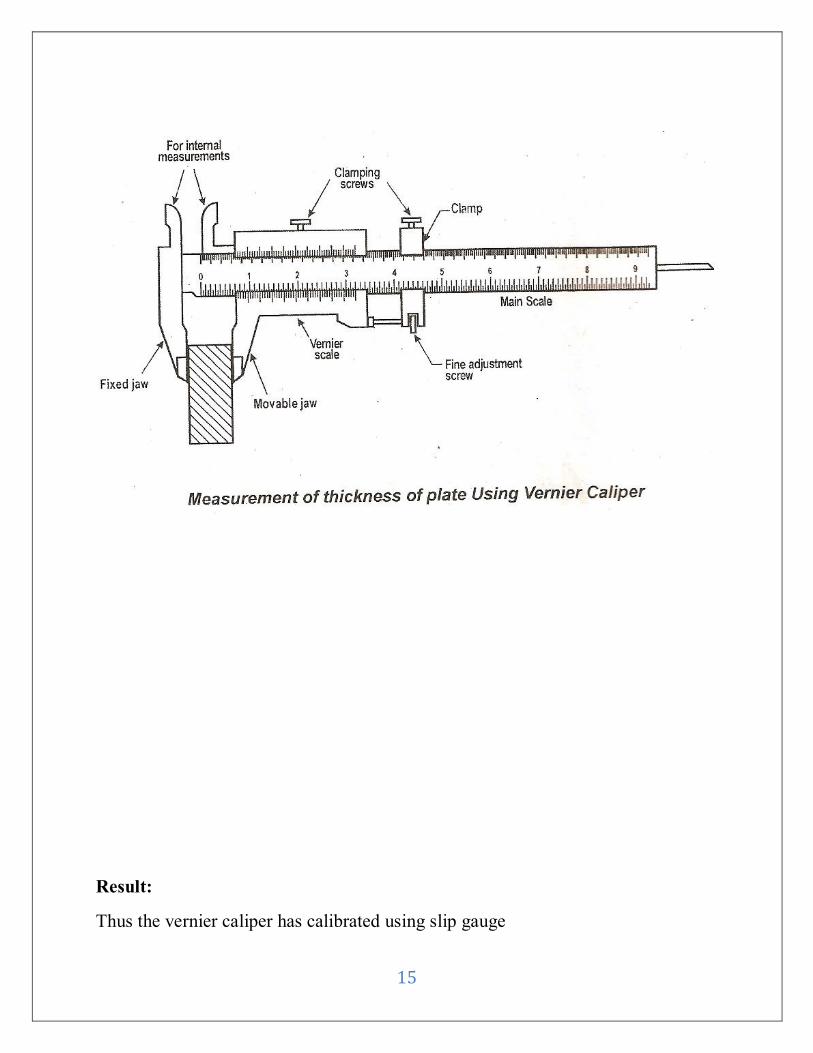
Vernier Caliper:
Vernier caliper has two sides’ namely main scale and vernier scale which
moves along the main scale vernier are used to measure both internal and external
dimension.
Procedure:
1. Vernier caliper is cleaned with a cloth.
2. The clamping screws are loosened.
3. The given component is fixed in both the two jaws.
4. The component should be perfectly holded.
5. The thickness is measured with the external jaws.
6. The length of the component is measured by adjusting the movable jaws.
7. The procedure is repeated for all the components. At least three readings
should be taken and then average will give the accurate measurement
14
Tabulation:
Least count=0.02mm
S.NO
VERNIER READING (mm) SLIP GAUGE
READINGS
(mm)
ERROR
(mm) MSR
(mm) VSR
TR
(mm)
Model Calculation:
Main scale reading = mm
Vernier scale coincides =
Total reading = MSR + (VSCXLC)
15
Result:
Thus the vernier caliper has calibrated using slip gauge
16
Ex No:
ANGLE OF TAPER BLOCK BY SINE BAR
Date :
Aim:
To measure the angle of the given taper block by using sine bar.
Instruments Required:
1. Sine bar
2. Slip gauge
3. Taper block
Formula:
Sin Ø = h / L
Where,
H - Height of the slip gauge
L - Distance between the centers
Ø - Inclined angle of the specimen
Description:
A Sine bar consist of an accurately ground bar since on which two accurately
ground cylinder of the same diameter are mounted at an exact distance apart. The
axis of the Cylinder on the plane that is parallel to the upper or working surface of
the sine bar .The axis of the cylinder are parallel to each other . The upper surface
has high degree of feathers.
The principal used in the measurement angle is that the sine of the given angle is
the ratio of the opposite side of the angle to the hypotenuse of the right angled
triangle.
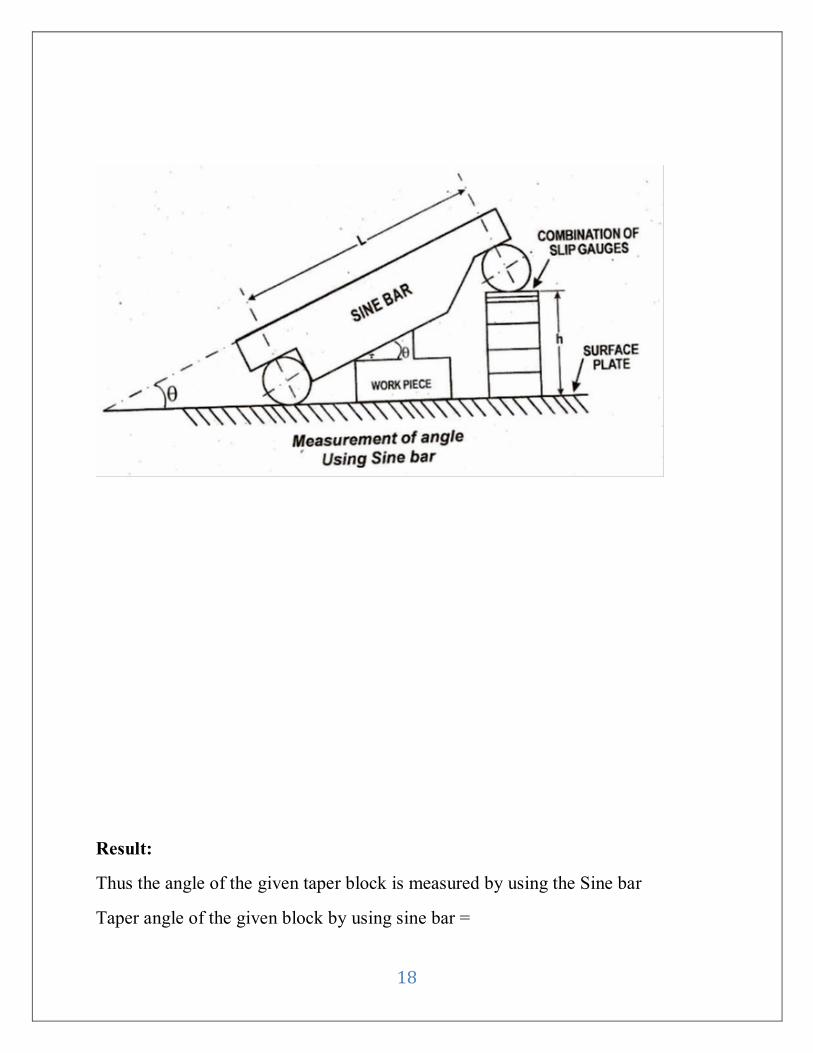
Procedure:
1. The given component is placed on the surface plate.
2. One roller of sine bar is placed on surface plate and bottom surface of sine
bar is seated on the taper surface of the component.
3. The combination of slip gauges is inserted between the second roller of sine
bar and the surface plate.
17
4. The angle of the component is then calculated by the formula given above.
Tabulation:
LENGTH OF
THE BAR
CENTER (L)
(mm)
h1
(mm)
h2
(mm)
h1- h2
(mm)
ANGLE OF
INCLINATION
OF SINE BAR
Model Calculation:
For measuring the angle of the given taper block by using the Sine bar
Sin Ф = h1-h2/ L
Ф =sin -1 (h1-h2 /L)
18
Result:
Thus the angle of the given taper block is measured by using the Sine bar
Taper angle of the given block by using sine bar =
19
Ex No:
ANGLE OF TAPER ROD BY SINE CENTER
Date :
Aim:
To measure the angle of the given taper block by using sine center and slip
gauge.
Instruments Required:
1. Sine center
2. Slip gauge
3. Dial gauge
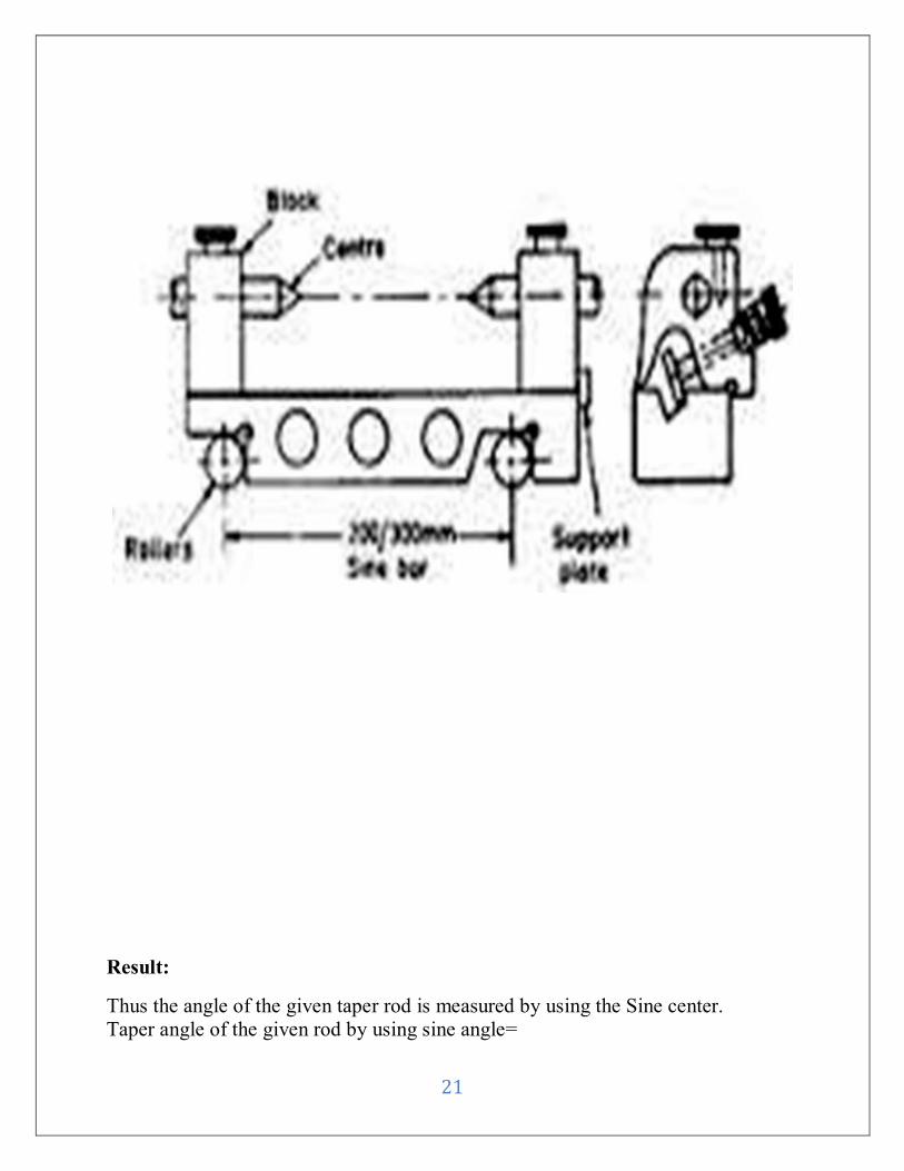
Description:
It is a sine center with block holding center which can be adjusted and
reading clamped in any position. A one center connection with slip gauge consists
of case fuel device for pressure measurement of conical between the centers. There
are made from high carbon chromium corrosive resistant steel hardened cylinders
of equal diameter are attached at ends then to each other and also parallel to equal
distance from the super surface of the sine center. The distance between the center
of two cylinder of the given sine center exactly 100mm.
Procedure:
1. To check and measure the angle the sine center is plane over the surface
plate.
2. The two center are clamped tightly place slip gauge below are one end to
other along the work rod and zero readings.
3. It is not added to few slip gauges in steps till the dial gauge move along
the work for the center and entire length of the taper readings is zero.
4. The angle is given by
Sin Ф = h1-h2 / L
Where,
Ф =Height of the slip gauge
20
h = Height between the cylinder
L = Length of the sine bar
Tabulation:
S.NO
DISTANCE
BETWEEN
ROLLERS “r”
(mm)
SLIP GAUGES h
mm
HALF
ANGLE h1
mm
h2
mm
Model Calculation:
For measuring the angle of the given taper rod by using the Sine center
Sin Ф = h/ L,
Ф =sin -1 (h /L)
21
Result:
Thus the angle of the given taper rod is measured by using the Sine center.
Taper angle of the given rod by using sine angle=
22
Ex No:
ANGLE OF V-BLOCK BY VERNIER BEVEL PROTRACTOR
Date :
Aim:
To measure the angle of V-block component by using vernier bevel
protractor.
Instruments Required:
1. Vernier bevel protector
2. V-block
Description:
Protector is an instrument used to measure and layout the angles with an optical
level protector. It is possible to read to an extent of Z. The blades present in the
protractor slides in its clamps. The unusual available blade lengths are 150mm and
300mm. inside the body protector there is a glass side. The stock and the body are
attached to each other such that the body are attached to each other such that the
outlet edges of the stock its tangential to the outside diameter of the body
The blades are clamped to the inner rotating member of the body. The inner
rotating member of the body carries a small eye piece. It is possible to view the
circle graduation against a fixed index circle.
Procedure:
1. For measuring the angle of V blocks the number of whole degree on the main
scale up to vernier center zero mark is noted in the vernier optical bevel
protector.
2. The mark in the main scale is found and this is added to the number of whole
degree to obtain the reading provision is made to adjust the focus of the optical
magnifying systems.
3. It is being adjusted in order to make accommodation of normal variation in eye
sight
23
Tabulation:
Least Count = 5’
S.No.
MSR
VSC
VSR
TR
„V‟ Block
angle
Error
Result:
Thus the angle of the given taper block is measured by using the optical
protector.
(i) Angle of V-blocks =
(ii) Angle of V-blocks =
24
Ex No:
MEASUREMENT OF SPUR GEAR TOOTH DIMENSIONS
Date :
Aim:
To measure gear parameter by using gear tooth vernier.
Instruments Required:
1. Gear tooth Vernier
2. Gear specimen.
Formula Used:
1. Depth, d = (Nm/2) (1+2/Z-COS(90/Z)
2. Width, w =Nm x sin (90/Z)
3. Outer diameter of gear, D =(Z+2)m
4. Module, m =D/(N+2)
Where,
w = Chordal width of tooth in mm
d = Chordal addendum of gear in mm
M = Module of gear in mm
N = NO. Of teeth
D = outside Dia in gear in mm
Procedure:
1. Find the zero error in the horizontal scale and vertical scale of the given gear
toot vernier.
2. Find outer diameter of the given gear by using vernier caliper.
3. Count the no of tooth on the given gear.
4. Calculate the depth of pitch circle from the top circle.
5. Calculate the module (m) of the gear.
6. Similarly calculate the theoretical width by substituting and no of gear tooth in
the formula.
7. The vertical gear tooth vernier is made of point to calculate the depth value.
8. Now the gear tooth, i.e. kept in between in the two jaws of the gear tooth
vernier.
9. Observe the main scale reading and vernier scale coincidence of the horizontal
scale.
10. Repeat the observation of different position of the same tooth and calculate the
average.
25
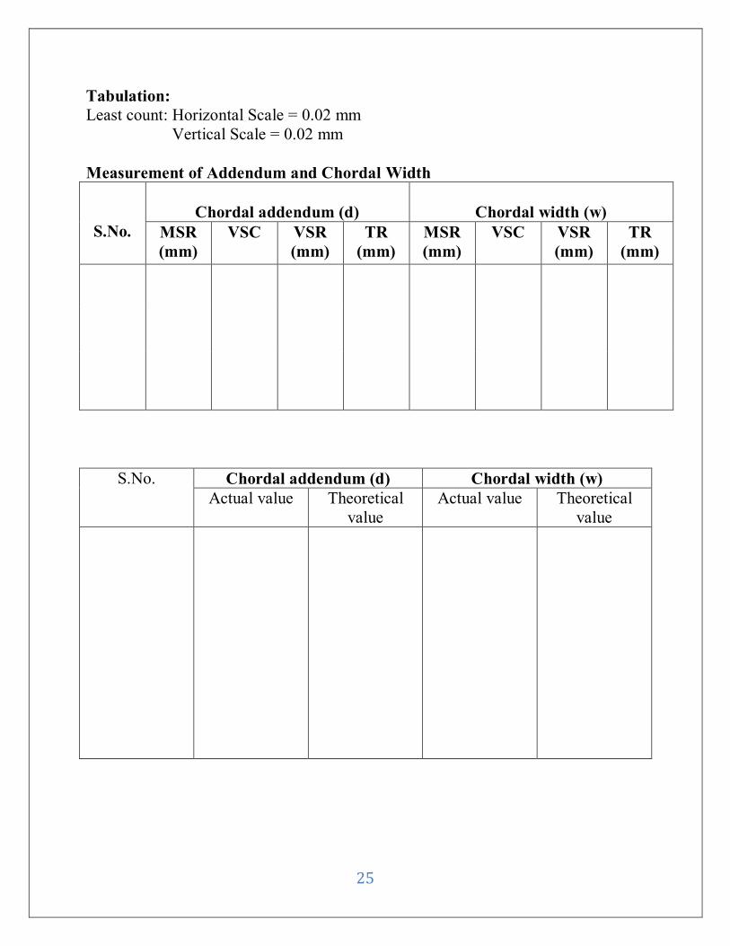
Tabulation:
Least count: Horizontal Scale = 0.02 mm
Vertical Scale = 0.02 mm
Measurement of Addendum and Chordal Width
S.No.
Chordal addendum (d)
Chordal width (w)
MSR
(mm)
VSC VSR
(mm)
TR
(mm)
MSR
(mm)
VSC VSR
(mm)
TR
(mm)
S.No. Chordal addendum (d) Chordal width (w)
Actual value Theoretical
value
Actual value Theoretical
value
26
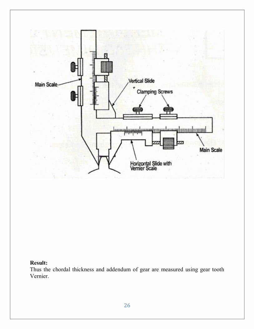
Result:
Thus the chordal thickness and addendum of gear are measured using gear tooth
Vernier.
27
Ex No:
MEASUEMENT OF SCREW THREAD USING PROFILE
PROJECTOR
Date :
Aim:
To determine the major and minor diameter, pitch and flank angle of a screw
tread using profile projector.
Instruments Required:
Profile projector
Screw thread
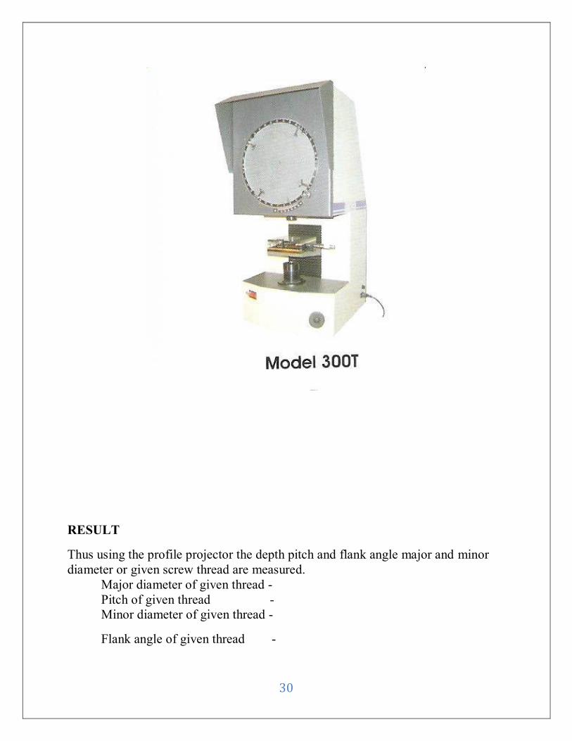
Description:
Profile Projector:
Profile projections are highly sophisticated and versatile designed as per
international standards. This comprehensive range covers all conceivable
application its ideal for the rapid inspection and measurement (linear and angular)
of small to medium size components such as watch parts, tools, rubber
components, miniature electronic assemblies and so on. It’s best quality high
resolution optics provides accurate, bright, clear and sharp images. The special
front and back surface mirror are highly polished and lobbied distortion and
reproduction. Three element condenser system and high intensity halogen lamps
provides brilliant images even in day light condition commitment to quality insure
that offer the highest level of precision, quality, reliability and performance.
Two types profile projectors are,
• Vertical floor model, ideal for the rapid inspection
• Horizontal floor model, ideal for the tracing for projected images
Procedure:
Measurement of Major Diameter:
The given material thread is placed horizontal plan plate of material
profile projector and transmitted light is switched on the vertical measurement
28
known is located fill of thread is on screen the difference of reading is major
diameter
Measurement:
The wire is made to coincide with and touch the line on one side of thread
and micrometer reading are noted the cross wire is coinciding to touch level on
other side.
The crosswire is to coincide on to root of one side of thread. The horizontal
Knob is adjusted to coincide on next root on same side.
The cross wire is made to coincide the root of v-groove of thread and the
angle of project is noted. The other side of V-groove is made to coincide with
wires of adjusting the projector. The difference is reading is twice the flank angle.
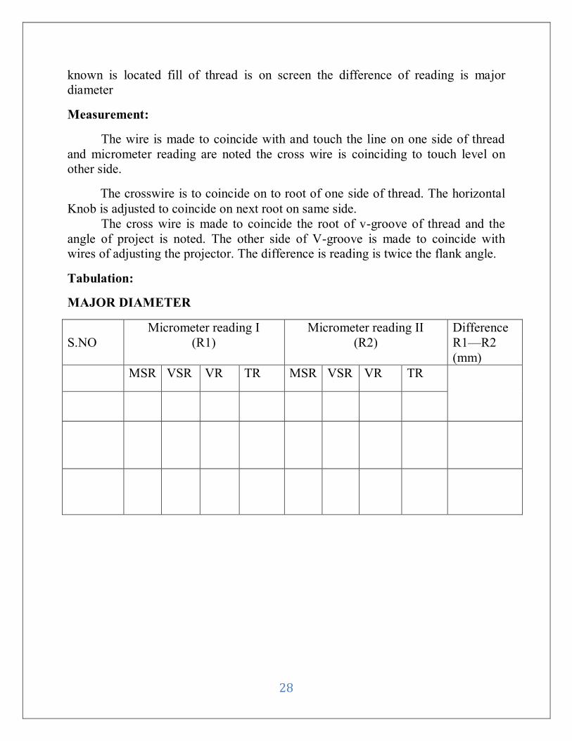
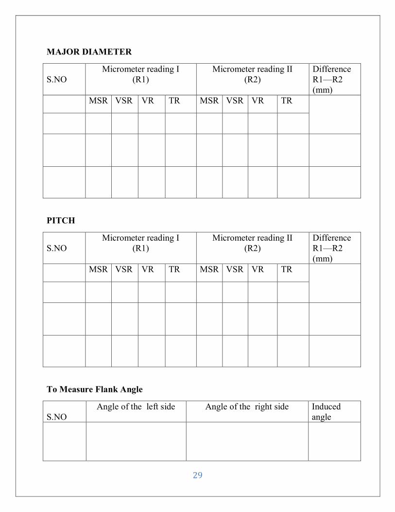
Tabulation:
MAJOR DIAMETER
S.NO
Micrometer reading I
(R1)
Micrometer reading II
(R2)
Difference
R1—R2
(mm)
MSR VSR VR TR MSR VSR VR TR
29
MAJOR DIAMETER
S.NO
Micrometer reading I
(R1)
Micrometer reading II
(R2)
Difference
R1—R2
(mm)
MSR VSR VR TR MSR VSR VR TR
PITCH
S.NO
Micrometer reading I
(R1)
Micrometer reading II
(R2)
Difference
R1—R2
(mm)
MSR VSR VR TR MSR VSR VR TR
To Measure Flank Angle
S.NO
Angle of the left side Angle of the right side Induced
angle
30
RESULT
Thus using the profile projector the depth pitch and flank angle major and minor
diameter or given screw thread are measured.
Major diameter of given thread -
Pitch of given thread -
Minor diameter of given thread -
Flank angle of given thread -
31
Ex No:
MEASUREMENT OF DISPLACEMENT USING LVDT
Date :
Aim:
To measure the displacement in terms of microns or mm using LVDT
system
Description:
The instruments is equipped with internal calibration setting which enables
the operator to calibrate only LVDT with the instrument provided the output of the
transducer for rated display is accurately known with the suitable extension units
the channels occupies can be increased and multipoint can be made faster response
a compared to the moving coil meter
Specification:
(i) LVDT displacement transducer
Voltage: 1-30 v
Frequency: 2 KHz
Sensitivity: (0.2-1)mv/v10 micron
Operating temperature:5-55ºC
Linearity elevation: 1%max
(ii) Displacement meter:
Transducer – LVDT
Range: 1999 micron/1.99 m
Frequency: 2 KHz
Frequency display: 3.5 digits LED display
Working temperature: 10-45ºC
Power requirement: 230V, 50 Hz, 1Ф
Procedure:
Null Balance:
LVDT transducer consists of primary coil and secondary coil round on a
cyclic bobbin. When the soft iron wire is put exactly in the middle and primary
windings is exited equal voltage are induced in secondary windings. The
differential voltage is proportional to the displacement of wire form centre. This
32
voltage is complicated phase directed and fed to the display. The null circuit is
used to reduce the finite output to minimum. Now the core is slightly moved so
that further reduction in value is got. By alternatively adjusting the core position
and null ball potentiometer. A minimum possible null voltage will be loss than
1mv rms
Zero Adjustment
After adjusting the null through zero control potentiometer on the barrel is
adjusted so that display range zero.
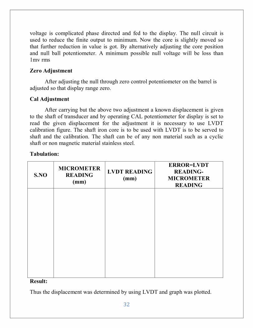
Cal Adjustment
After carrying but the above two adjustment a known displacement is given
to the shaft of transducer and by operating CAL potentiometer for display is set to
read the given displacement for the adjustment it is necessary to use LVDT
calibration figure. The shaft iron core is to be used with LVDT is to be served to
shaft and the calibration. The shaft can be of any non material such as a cyclic
shaft or non magnetic material stainless steel.
Tabulation:
S.NO
MICROMETER
READING
(mm)
LVDT READING
(mm)
ERROR=LVDT
READING-
MICROMETER
READING
Result:
Thus the displacement was determined by using LVDT and graph was plotted.
33
Ex No:
MEASUREMENT OF VIBRATION PARAMETERS USING
VIBRATION SET UP
Date :
Aim:
To study the various parameters involved in the vibrations of a given system.
To plot the characteristic curves of the given specimen
Instruments Required:
1, Vibration exciter
2, Vibration pick-up
3, Vibration analyzer
4, Power amplifier
5, Oscillator
Description:
The mechanical vibration, if not within limits may cause damage to the
materials, structures associated with it.
Vibration exciter is an electrodynamic device. It consists of a powerful
magnet placed centrally surrounding which is suspended the exciter coil. This
assembly is enclosed by a high permeability magnetic circuit.
When an electrical current is passed through the exciter coil, a magnetic
field is created around the coil resulting in the upward or downward movement of
the suspended coil depending upon the direction of the current flow in the coil.
Thus controlling the frequency of the coil current, the frequency of vibration is
controlled. Power amplifier is the control unit for the exciter.
Piezo – electric crystals produce an emf when they are deformed. This output
emf may be measured to know the value of applied force and hence the pressure.
34
A piezo – electric material is one in which an electric potential appears
across certain surfaces of a crystal of the dimensions of the crystal are charged by
the application of a mechanical force. The effect is reversible.
Common piezo – electric materials include quartz, Rochelle salt, lithium
sulphate etc.,
Caution:
Do not remove the fuse cap while power chord is connected to 230V AC mains
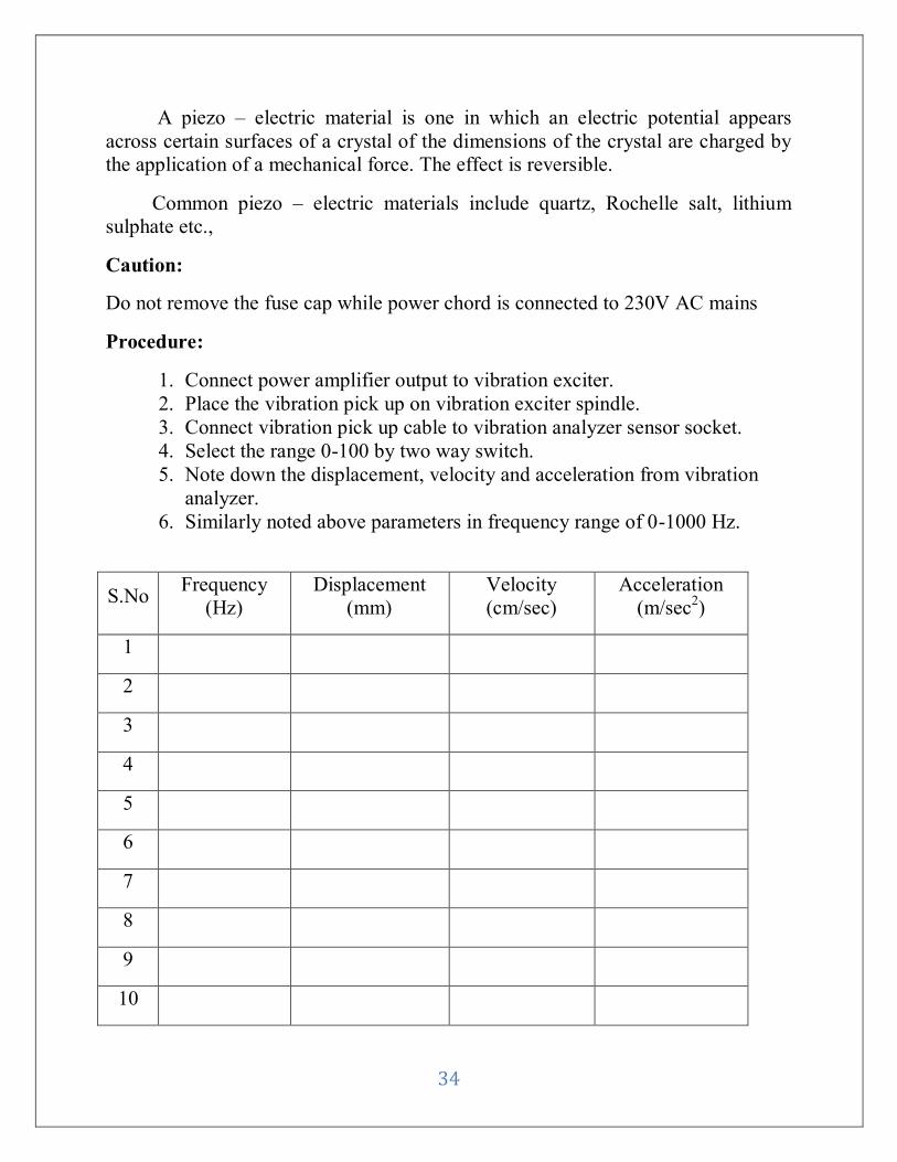
Procedure:
1. Connect power amplifier output to vibration exciter.
2. Place the vibration pick up on vibration exciter spindle.
3. Connect vibration pick up cable to vibration analyzer sensor socket.
4. Select the range 0-100 by two way switch.
5. Note down the displacement, velocity and acceleration from vibration
analyzer.
6. Similarly noted above parameters in frequency range of 0-1000 Hz.
S.No Frequency
(Hz)
Displacement
(mm)
Velocity
(cm/sec)
Acceleration
(m/sec2)
1
2
3
4
5
6
7
8
9
10
35
Result:
Various parameters of vibration such as displacement, velocity and acceleration are
studied and the following characteristic curves were plotted.
1. Displacement Vs Frequency =
2. Velocity Vs Frequency =
3. Acceleration Vs Frequency =
36
Ex No:
MEASUREMENT OF STRAIGHTNESS AND FLATNESS USING
TWO AXIS AUTO COLLIMATOR
Date :
Aim:
To measure the straightness and Flatness given specimen using two axis auto
collimator.
Instruments required:
Collimator unit, Base, plain reflector, optical Scanner
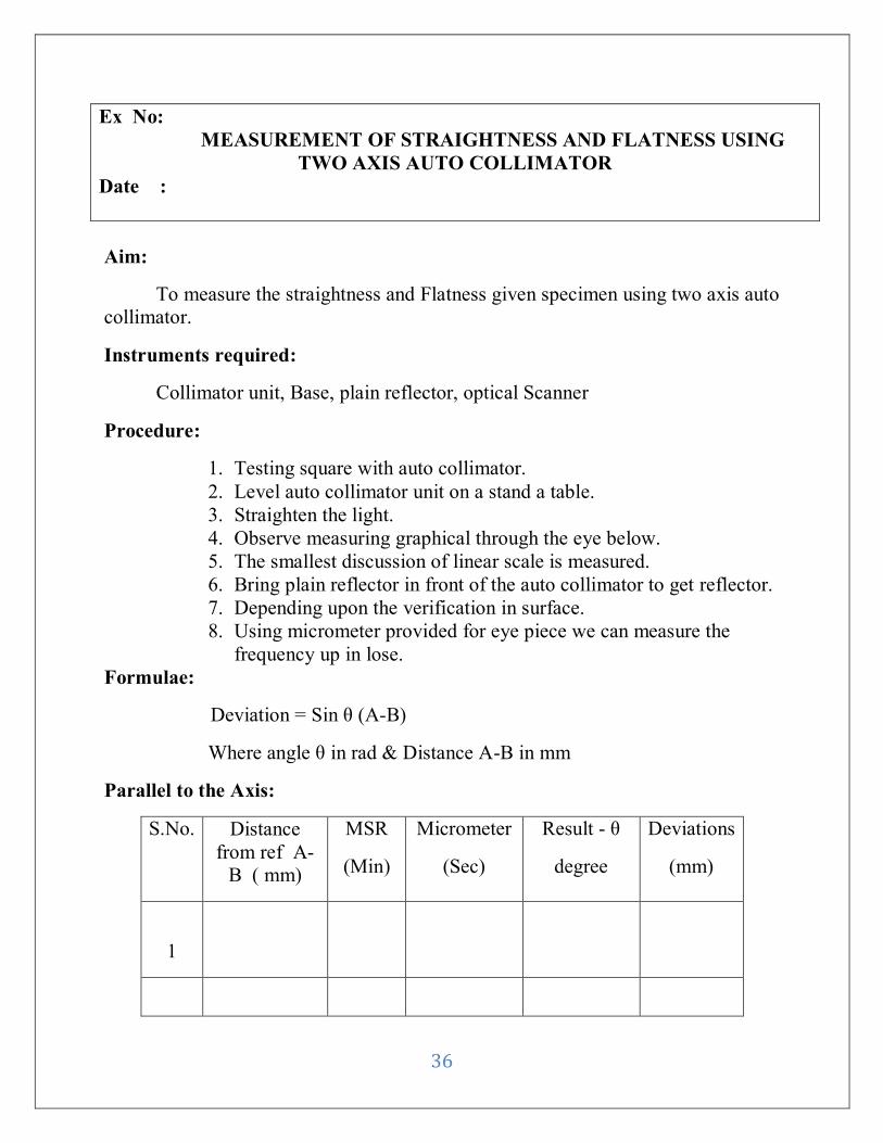
Procedure:
1. Testing square with auto collimator.
2. Level auto collimator unit on a stand a table.
3. Straighten the light.
4. Observe measuring graphical through the eye below.
5. The smallest discussion of linear scale is measured.
6. Bring plain reflector in front of the auto collimator to get reflector.
7. Depending upon the verification in surface.
8. Using micrometer provided for eye piece we can measure the
frequency up in lose.
Formulae:
Deviation = Sin θ (A-B)
Where angle θ in rad & Distance A-B in mm
Parallel to the Axis:
S.No. Distance
from ref A-
B ( mm)
MSR
(Min)
Micrometer
(Sec)
Result - θ
degree
Deviations
(mm)
1
37
2
3
4
5
6
Perpendicular to the Axis:
Sl.no Distance
from ref A-
B ( mm)
MSR
(Min)
Micrometer
(Sec)
Result - θ
Degree
Deviations
(mm)
1
2
3
4
5
6
38
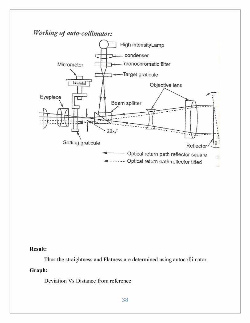
Result:
Thus the straightness and Flatness are determined using autocollimator.
Graph:
Deviation Vs Distance from reference
39
Ex No:
FORCE MEASUREMENT
Date :
Aim:
To measure the force using load cell.
Instruments Required:
1. Proving Ring
2. Load cell
3. Force indicator
4. Screw jack
5. Dial gauge.
6. Capacity of proving Ring =2.5 KN.
Description:
Force is one of the major derived parameter having fundamental
dimension of mass length and time. It is a vector quantity which, when applied
result in a change of momentum in a body. Basically mechanical force is created
due to variation of started potential energy.
This is different types of load cell like column type, shear type, s-type,
and compression type. In this setup, s-type load cell is provided.
Procedure:
1. Ensure that proving ring along with load all is perfectly in vertical position.
2. Check and ensure that the axis of screw jacks perfectly aligned with load cell.
3. Ensure that load cell with socket is connected to the rear side of the load
indicator.
4. Apply a small load without any slip in the system.
5. Note down the reading of dial gauge of force indicator.
40
Sl.no Actual load applied
(kg)
Deflection (div)
1
2
3
4
5
6
7
8
9
10
1 division = 0.002mm
Result:
Thus the force measurement has been measured using load cell.
Graph: Deflection Vs Applied load
41
Ex No:
TEMPERATURE MEASUREMENT
Date :
Aim:
To measure the temperature using copper constantan thermo couple.
Instruments Required:
1. Thermo couple
2. Temperature measuring setup.
3. Ice cubes.
Procedure:
1. Connect the thermocouple supplied at the input terminal if copper constantan
Thermocouple is used. Copper wire must be connected to the terminal and
constantan wire to –ve terminal.
2. Immerse the junction of thermocouple in ice and adjust the meter reading at 0° C
using potentiometer.
3. Immerse the junction of thermocouple in boiling at 98° C by using
Potentiometer marked max.
4. Repeat the procedure for 2 to 3 times.
Sl.No Actual
temperature C°
Indicated
temperature C°
1
2
3
4
5
42
6
7
8
9
10
Result:
Thus the temperature is measured using thermocouple.
Graph:
Indicated Temperature Vs Actual Temperature
43
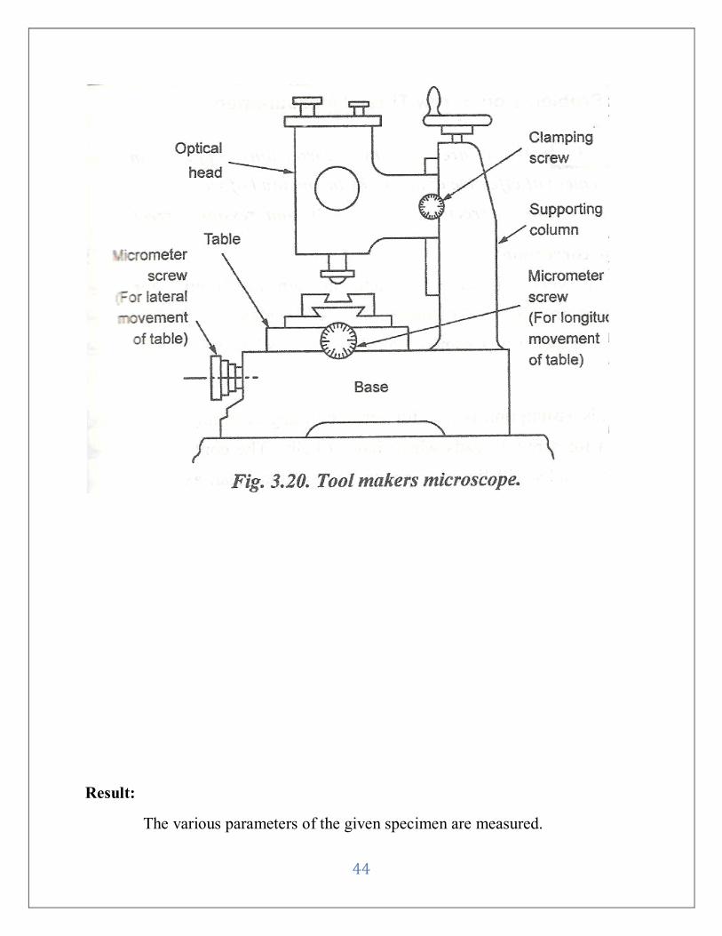
Ex No:
MEASUREMENT OF DIMENSION OF GIVEN SPECIMEN USING
TOOL MAKER‟S MICROSCOPE
Date :
Aim:
To measure various dimension of a given specimen using Tool maker’s
microscope.
Instruments Required:
Tool maker’s microscope, Specimen, Eyepiece.
Procedure:
1. To find the Major and Minor diameter:
One end of screw thread in made to coincide with cross wire & fixed.
Reading is taken. The different between readings given linear measurement.
2. Measurement of pitch:
The contour is get so that the same it an screen. The reading of
micrometer is noted. The reading of are subtracted & different is noted.
3. Measurement of thread angle:
The screw is rotated till linear cross wire coincides with flank of thread
profile. The angle of screw rotation and than the same line coincides with flank
thread.
44
Result:
The various parameters of the given specimen are measured.