DATAQ Instruments' hardware and software products are not designed to be used in the diagnosis and treatment of humans, nor are they to be used as critical components in any life-support systems whose failure to perform can rea-sonably be expected to cause significant injury to humans.
DATAQ, the DATAQ logo, and WINDAQ are registered trademarks of DATAQ Instruments, Inc. All rights reserved.
DATAQ Instruments, Inc.241 Springside Drive
Akron, Ohio 44333 U.S.A.Telephone: 330-668-1444
Fax: 330-666-5434Designed and manufactured in the
United States of America
Warranty and Service PolicyProduct WarrantyDATAQ Instruments, Inc. warrants that this hardware will be free from defects in materials and workmanship under normal use and service for a period of 90 days from the date of shipment. DATAQ Instruments' obligations under this warranty shall not arise until the defective material is shipped freight prepaid to DATAQ Instruments. The only responsibility of DATAQ Instruments under this warranty is to repair or replace, at its discretion and on a free of charge basis, the defective material.
This warranty does not extend to products that have been repaired or altered by persons other than DATAQ Instru-ments employees, or products that have been subjected to misuse, neglect, improper installation, or accident.
DATAQ Instruments shall have no liability for incidental or consequential damages of any kind arising out of the sale, installation, or use of its products.
Service Policy
1. All products returned to DATAQ Instruments for service, regardless of warranty status, must be on a freight-pre-paid basis.
2. DATAQ Instruments will repair or replace any defective product within 5 days of its receipt.
3. For in-warranty repairs, DATAQ Instruments will return repaired items to the buyer freight prepaid. Out of war-ranty repairs will be returned with freight prepaid and added to the service invoice.
iii
DI-1120 Hardware Manual
Table of ContentsWarranty and Service Policy ................................................................................................................ iii1. Introduction ........................................................................................................................................ 1
Install WinDaq Software ................................................................................................................... 7Connect the Instrument to Your Computer ....................................................................................... 8
4. Controls, Indicators, and Connections ............................................................................................. 9Mini-B USB Connection ................................................................................................................... 9Screw Terminals ................................................................................................................................ 9
DI-1120 Signal Connections ....................................................................................................... 10Connecting Signal Leads ............................................................................................................ 10Analog Inputs .............................................................................................................................. 11
Low-pass Filter ..................................................................................................................... 12Resolution as a Function of Sample Rate ............................................................................. 13
1. IntroductionThis manual contains information designed to familiarize you with the features and functions of the DI-1120 USB data acquisition system.
FeaturesThe DI-1120 data acquisition instrument is a portable data recording module that communicates through your com-puter's USB port. Power is derived from the interface port so no external power is required. Features include:
• 4 fixed differential analog inputs protected to 120 V rms.
• ±2, ±5, ±10, ±20, ±50, ±100 V full scale measurement range, programmable per channel.
• 7 digital ports protected to +25V: Two dedicated for WINDAQ remote control operations; One dedicated to WINDAQ rate measurements; and One dedicated to WINDAQ counter measurements.
• 12- to 14-bit measurement resolution as a function of sample rate.
• Up to 160 kHz maximum throughput sampling rate.
• A push-button to tag remote events in WINDAQ software.
• LED indication for easy notification of system status.
• Free WinDaq/Lite data acquisition recording software.
• ChannelStretch™ Technology allows you to synchronize up to 16 units with a total throughput of 480kHz or more.*
• Included .Net Class supports programming the DI-1120 under any .Net programming language.*
• Fully documented instrument protocol for programming the device in operating systems other than Windows.*
*ChannelStretch requires that each device be unlocked when used with WinDaq software. WinDaq unlock is not required for ChannelStretch if programming devices yourself using the .Net class or instrument protocol.
Analog InputsThe DI-1120 features four differential channel inputs located on a single sixteen-position screw terminal block for easy connection and operation. Measurement ranges of ±2, ±5, ±10, ±20, ±50 or ±100 Volts are programmable on a per channel basis. Analog channels are protected to 120 V rms.
Utilize the functionality of WINDAQ software to experience all the features encased in these small, inexpensive instruments. Unlock code required to record more than one DI-1120 at a time.
Digital I/OThe DI-1120 contains seven digital ports, which may be used as a general-purpose digital inputs or for a specific function as designated on the device. Digital port D0 is reserved for WinDaq Events; Digital port D1 is reserved for WinDaq remote Start/Stop; Digital port D2 is reserved for rate measurements; Digital port D3 is reserved for counts; Please Note: Digital outputs are not supported in WinDaq software. Each port may be configured as a switch using third-party software.
SoftwareAll software required to record and playback waveforms is included with the purchase of any DI-1120 data acquisi-tion system via download.
Introduction1
DI-1120 Hardware Manual
WINDAQ® Recording and Playback SoftwareWINDAQ Acquisition and WINDAQ Waveform Browser allow you to record and playback data acquired through your instrument. WINDAQ software is an invaluable resource to record and analyze your data and is available for free from our web site (www.dataq.com).
WINDAQ Lite Data Acquisition software (free) can be used to record waveforms directly and continuously to disk while monitoring a real time display of the waveforms on-screen. It operates, displays, and records all the channels from a single device in real time. An optional unlock code is available to enable ChannelStretch™ expansion when running WinDaq software.
WINDAQ Waveform Browser playback software (also known as “WWB”) offers an easy way to review and analyze acquired waveforms. A built-in data file translator allows the user to display multiple waveforms acquired by WINDAQ Acquisition software or any of a wide range of data acquisition packages. The software’s disk-streaming design allows data files of any length to be graphically displayed rapidly, in normal or reverse time directions. Seven standard cursor-based measurements, frequency domain, and statistical analysis functions help simplify waveform analysis and interpretation. WINDAQ Waveform Browser is free and installed when installing WINDAQ Software.
HelpAll WINDAQ software utilizes context-sensitive help. Help may be accessed through the Help menu or by pressing the F1 key with any pull-down menu item selected. This will take you directly to the Help topic most relevant to that par-ticular function or feature. Help topics discuss in detail each function available in the software.
2. SpecificationsAnalog InputsNumber of Channels: 4
Channel Configuration: Differential
Full Scale Range: ±2, 5, 10, 20, 50 100 V
Input impedance: 795k
Absolute accuracy:@ 25°C, excluding common mode error
0.25% of full scale range
Absolute maximum input without damage: 120 V rms (normal mode + common mode)
Common mode range: ±20 V dc or peak ac
Common mode rejection ratio: 50 dB (dc - 60 Hz)
Channel-to-channel crosstalk rejection: -50 dB
Digital PortsNumber of Ports: 7
Type: MOSFET switch
Configuration: Programmable as digital input or switch
Pull-up value: 4.7 k
Input high voltage threshold: 2.4V
Input low voltage threshold: 0.8V
Absolute maximum applied voltage (V): +25V
Reserved Digital InputsD0: WINDAQ remote events
D1: WINDAQ remote start/stop
D2: Rate input
D3: Count input
ADC CharacteristicsResolution: 12- to 14-bit
Above zero ADC counts: 2,047 to 8,191Below zero ADC counts: 2,048 to 8,192
Max. sample throughput rate: 160 kHz
Min. sample throughput rate: Hardware only: 20 HzWinDaq software: 2.2 samples per hour
Sample rate timing accuracy: 50 ppm
Digital Ports Programmed as SwitchMaximum drain voltage: 25V
Maximum sink current: 100 mA
Specifications3
DI-1120 Hardware Manual
Count/RateDigital port assignment: Count: D3 configured as input
Rate: D2 configured as input
Terminal count: 65,535
Maximum rate frequency: 50 KHz with one enabled channel, 20 KHz with 2-4 enabled channels, 10 KHz with 5-7 enabled channels
Minimum rate frequency: 0.5 Hz
Maximum count frequency: 50 kHz
Indicators and ConnectionsInterface: USB 2.0 (mini-B style connector)
Indicator light: 3 LEDs
Input connections: Two 16-position screw terminal strips
ChannelStretch™ OperationMaximum number of DI-1120 units: 16
Maximum channel count: 64 analog, 112 digital
Maximum supported throughput: ≥480 kHz
Synchronization conditions: All instruments must be configured for the same sample rate per channel, ≤20 kHz. Enabled channels per instrument are independent of measure-ment function and range.
PC USB prerequisite: All instruments must be connected to the same USB controller. The use of USB hubs are recommended to meet this requirement.
PowerPower Consumption: <1.0 Watt, via USB interface
EnvironmentalOperating Temperature: 0°C to 50°C (32°F to 122°F)
Operating Humidity: 0 to 90% non-condensing
Storage Temperature: -20°C to 60°C (-4°F to 140°F)
Programming: DATAQ .NET Class, Instrument protocol, ActiveX Control
Specifications5
DI-1120 Hardware Manual
3. InstallationThe following items are included with each DI-1120 USB Data Acquisition System. Verify that you have the follow-ing:
• A DI-1120 USB data acquisition instrument.
• 6-foot USB cable.
• A DATAQ Instruments screwdriver for signal lead connections.
If an item is missing or damaged, call DATAQ Instruments at 330-668-1444. We will guide you through the appropri-ate steps for replacing missing or damaged items. Save the original packing material in the unlikely event that your unit must, for any reason, be sent back to DATAQ Instruments.
Install WINDAQ SoftwareAll software for the DI-1120 can be installed via a downloadable executable directly from the DATAQ Instruments web site. No CD is shipped with the device. You may burn the executable onto a CD to transport the software to a computer with no internet connection.
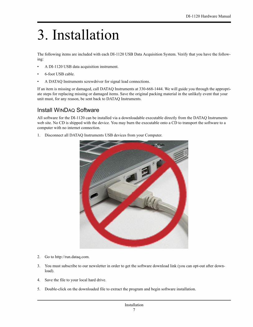
1. Disconnect all DATAQ Instruments USB devices from your Computer.
2. Go to http://run.dataq.com.
3. You must subscribe to our newsletter in order to get the software download link (you can opt-out after down-load).
4. Save the file to your local hard drive.
5. Double-click on the downloaded file to extract the program and begin software installation.
Installation7
DI-1120 Hardware Manual
6. Follow the on-screen prompts and enter any required information.
7. Software installation is complete - you will now see a “Successful Installation” box - click OK to exit WINDAQ
Installation.
You can now plug the device(s) into your PC. Access WinDaq software using the shortcut generated during installa-tion.
Connect the Instrument to Your ComputerDI-1120 instruments can be connected to your computer’s USB port using the provided USB cable. No external power is required. Connect one end of the communications cable to the instrument port and the other to your PC’s port.
Note: Use a powered USB hub or a USB port on your PC. Non-powered USB hubs may not have sufficient power to run the instrument.
Installation8
DI-1120 Hardware Manual
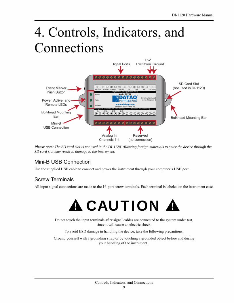
4. Controls, Indicators, and Connections
Please note: The SD card slot is not used in the DI-1120. Allowing foreign materials to enter the device through the SD card slot may result in damage to the instrument.
Mini-B USB ConnectionUse the supplied USB cable to connect and power the instrument through your computer’s USB port.
Screw TerminalsAll input signal connections are made to the 16-port screw terminals. Each terminal is labeled on the instrument case.
CAUTION
Do not touch the input terminals after signal cables are connected to the system under test,since it will cause an electric shock.
To avoid ESD damage in handling the device, take the following precautions:
Ground yourself with a grounding strap or by touching a grounded object before and duringyour handling of the instrument.
www.dataq.com
+ - + -+ -+ -D5D4 D6 GnD+5V
Power
Remote
Active
-+Ch1
-+Ch2
-+Ch3
-+Ch4
Model DI-1120
Reserved (no connection)Analog Inputs (±2 to 100 VFS, 120V rms max)
+ - + -+ -+ -Digital Ports (25 V @ 100mA max.)
Data Acquisition Starter Kit
Download software
at run.dataq.com
Rate/D2 Cnt/D3Rcrd/D1Evnt/D0
Analog In
Channels 1-4
Reserved
(no connection)
Digital Ports
Power, Active, and
Remote LEDs
Event Marker
Push Button
Mini-B
USB Connection
SD Card Slot
(not used in DI-1120)
Bulkhead Mounting
Ear Bulkhead Mounting Ear
+5V
Excitation Ground
! !
Controls, Indicators, and Connections9
DI-1120 Hardware Manual
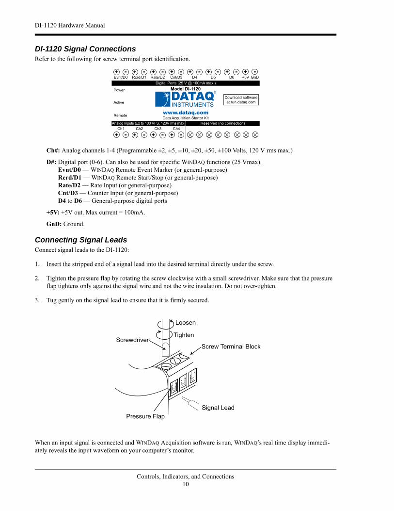
DI-1120 Signal ConnectionsRefer to the following for screw terminal port identification.
Ch#: Analog channels 1-4 (Programmable ±2, ±5, ±10, ±20, ±50, ±100 Volts, 120 V rms max.)
D#: Digital port (0-6). Can also be used for specific WINDAQ functions (25 Vmax).Evnt/D0 — WINDAQ Remote Event Marker (or general-purpose) Rcrd/D1 — WINDAQ Remote Start/Stop (or general-purpose)Rate/D2 — Rate Input (or general-purpose)Cnt/D3 — Counter Input (or general-purpose)D4 to D6 — General-purpose digital ports
+5V: +5V out. Max current = 100mA.
GnD: Ground.
Connecting Signal LeadsConnect signal leads to the DI-1120:
1. Insert the stripped end of a signal lead into the desired terminal directly under the screw.
2. Tighten the pressure flap by rotating the screw clockwise with a small screwdriver. Make sure that the pressure flap tightens only against the signal wire and not the wire insulation. Do not over-tighten.
3. Tug gently on the signal lead to ensure that it is firmly secured.
When an input signal is connected and WINDAQ Acquisition software is run, WINDAQ’s real time display immedi-ately reveals the input waveform on your computer’s monitor.
www.dataq.com
+ - + -+ -+ -D5D4 D6 GnD+5V
Power
Remote
Active
-+Ch1
-+Ch2
-+Ch3
-+Ch4
Model DI-1120
Reserved (no connection)Analog Inputs (±2 to 100 VFS, 120V rms max)
+ - + -+ -+ -Digital Ports (25 V @ 100mA max.)
Data Acquisition Starter Kit
Download software
at run.dataq.com
Rate/D2 Cnt/D3Rcrd/D1Evnt/D0
Controls, Indicators, and Connections10
DI-1120 Hardware Manual
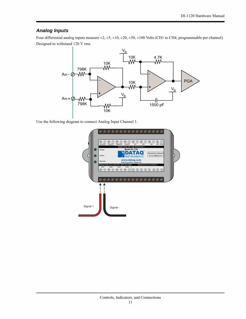
Analog Inputs
Four differential analog inputs measure ±2, ±5, ±10, ±20, ±50, ±100 Volts (CH1 to CH4, programmable per channel).
Designed to withstand 120 V rms.
Use the following diagram to connect Analog Input Channel 1.
798K
AIN
798K
10K
10K
AIN
VB
10K
VB
10K 4.7K
VB
1500 pF
PGA
Signal + Signal -
www.dataq.com
+ - + -+ -+ -D5D4 D6 GnD+5V
Power
Remote
Active
-+Ch1
-+Ch2
-+Ch3
-+Ch4
Model DI-1120
Reserved (no connection)Analog Inputs (±2 to 100 VFS, 120V rms max)
+ - + -+ -+ -Digital Ports (25 V @ 100mA max.)
Data Acquisition Starter Kit
Download software
at run.dataq.com
Rate/D2 Cnt/D3Rcrd/D1Evnt/D0
Controls, Indicators, and Connections11
DI-1120 Hardware Manual
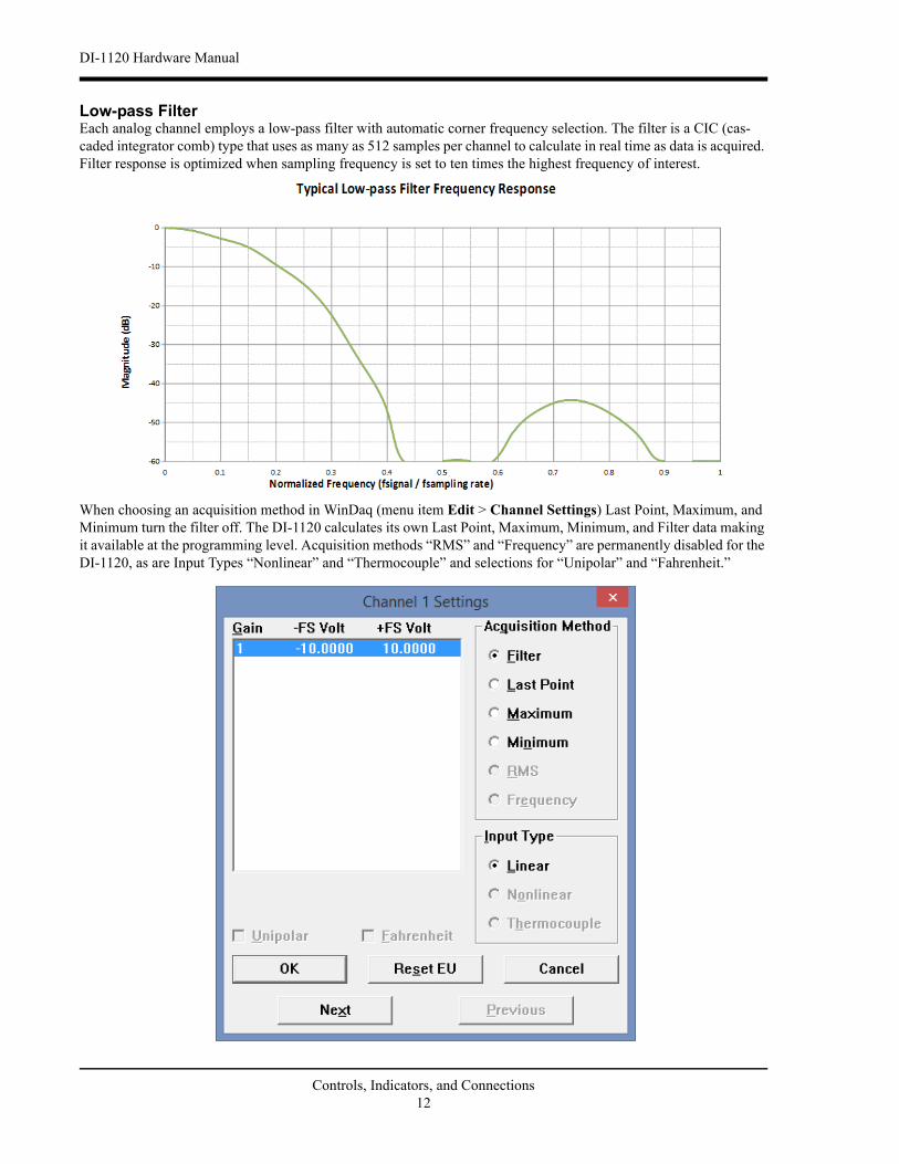
Low-pass FilterEach analog channel employs a low-pass filter with automatic corner frequency selection. The filter is a CIC (cas-caded integrator comb) type that uses as many as 512 samples per channel to calculate in real time as data is acquired. Filter response is optimized when sampling frequency is set to ten times the highest frequency of interest.
When choosing an acquisition method in WinDaq (menu item Edit > Channel Settings) Last Point, Maximum, and Minimum turn the filter off. The DI-1120 calculates its own Last Point, Maximum, Minimum, and Filter data making it available at the programming level. Acquisition methods “RMS” and “Frequency” are permanently disabled for the DI-1120, as are Input Types “Nonlinear” and “Thermocouple” and selections for “Unipolar” and “Fahrenheit.”
Controls, Indicators, and Connections12
DI-1120 Hardware Manual
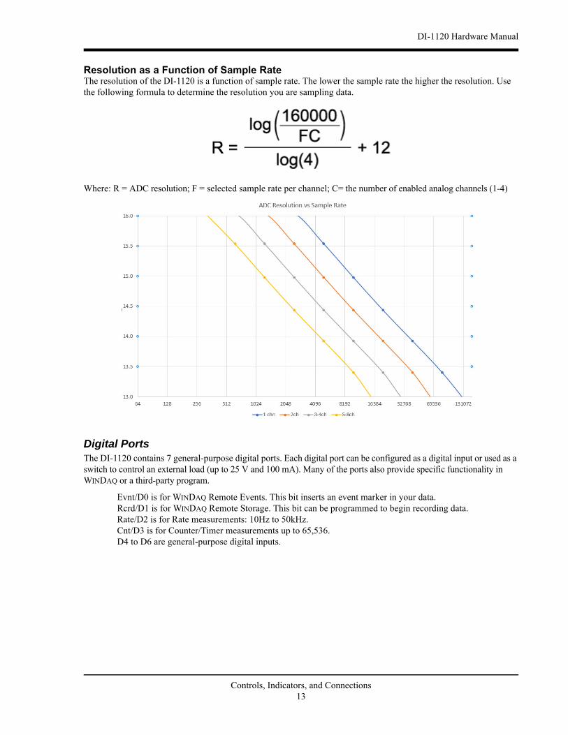
Resolution as a Function of Sample RateThe resolution of the DI-1120 is a function of sample rate. The lower the sample rate the higher the resolution. Use the following formula to determine the resolution you are sampling data.
Where: R = ADC resolution; F = selected sample rate per channel; C= the number of enabled analog channels (1-4)
Digital PortsThe DI-1120 contains 7 general-purpose digital ports. Each digital port can be configured as a digital input or used as a switch to control an external load (up to 25 V and 100 mA). Many of the ports also provide specific functionality in WINDAQ or a third-party program.
Evnt/D0 is for WINDAQ Remote Events. This bit inserts an event marker in your data.Rcrd/D1 is for WINDAQ Remote Storage. This bit can be programmed to begin recording data.Rate/D2 is for Rate measurements: 10Hz to 50kHz.Cnt/D3 is for Counter/Timer measurements up to 65,536.D4 to D6 are general-purpose digital inputs.
Controls, Indicators, and Connections13
DI-1120 Hardware Manual
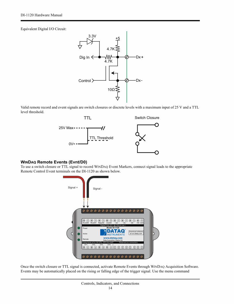
Equivalent Digital I/O Circuit:
Valid remote record and event signals are switch closures or discrete levels with a maximum input of 25 V and a TTL level threshold.
WINDAQ Remote Events (Evnt/D0)To use a switch closure or TTL signal to record WINDAQ Event Markers, connect signal leads to the appropriate Remote Control Event terminals on the DI-1120 as shown below.
Once the switch closure or TTL signal is connected, activate Remote Events through WINDAQ Acquisition Software. Events may be automatically placed on the rising or falling edge of the trigger signal. Use the menu command
Dig In Dx
Dx
10
4.7K
+5
4.7K
Control
3.3V
Switch ClosureTTL
0V
25V Max
TTL Threshold
Signal + Signal -
www.dataq.com
+ - + -+ -+ -D5D4 D6 GnD+5V
Power
Remote
Active
-+Ch1
-+Ch2
-+Ch3
-+Ch4
Model DI-1120
Reserved (no connection)Analog Inputs (±2 to 100 VFS, 120V rms max)
+ - + -+ -+ -Digital Ports (25 V @ 100mA max.)
Data Acquisition Starter Kit
Download software
at run.dataq.com
Rate/D2 Cnt/D3Rcrd/D1Evnt/D0
Controls, Indicators, and Connections14
DI-1120 Hardware Manual
Options > Remote Events + to set WINDAQ to place event markers on low-to-high transitions of the Event input. Use the menu command Options > Remote Events - to set WINDAQ to place event markers on high-to-low transi-tions of the Event input.
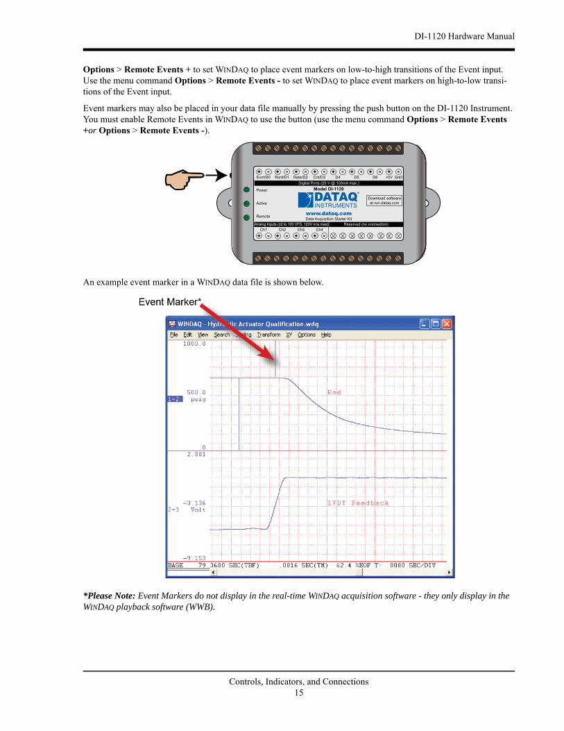
Event markers may also be placed in your data file manually by pressing the push button on the DI-1120 Instrument. You must enable Remote Events in WINDAQ to use the button (use the menu command Options > Remote Events +or Options > Remote Events -).
An example event marker in a WINDAQ data file is shown below.
*Please Note: Event Markers do not display in the real-time WINDAQ acquisition software - they only display in the WINDAQ playback software (WWB).
www.dataq.com
+ - + -+ -+ -D5D4 D6 GnD+5V
Power
Remote
Active
-+Ch1
-+Ch2
-+Ch3
-+Ch4
Model DI-1120
Reserved (no connection)Analog Inputs (±2 to 100 VFS, 120V rms max)
+ - + -+ -+ -Digital Ports (25 V @ 100mA max.)
Data Acquisition Starter Kit
Download software
at run.dataq.com
Rate/D2 Cnt/D3Rcrd/D1Evnt/D0
Controls, Indicators, and Connections15
DI-1120 Hardware Manual
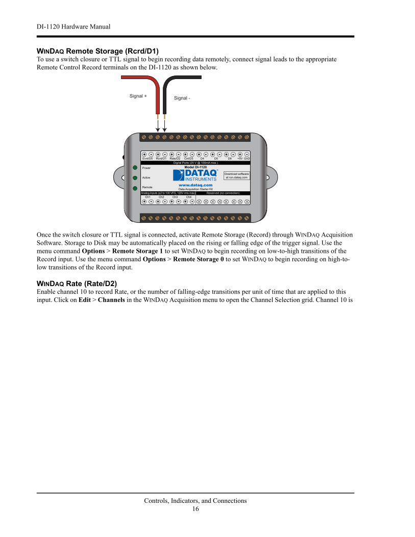
WINDAQ Remote Storage (Rcrd/D1)To use a switch closure or TTL signal to begin recording data remotely, connect signal leads to the appropriate Remote Control Record terminals on the DI-1120 as shown below.
Once the switch closure or TTL signal is connected, activate Remote Storage (Record) through WINDAQ Acquisition Software. Storage to Disk may be automatically placed on the rising or falling edge of the trigger signal. Use the menu command Options > Remote Storage 1 to set WINDAQ to begin recording on low-to-high transitions of the Record input. Use the menu command Options > Remote Storage 0 to set WINDAQ to begin recording on high-to-low transitions of the Record input.
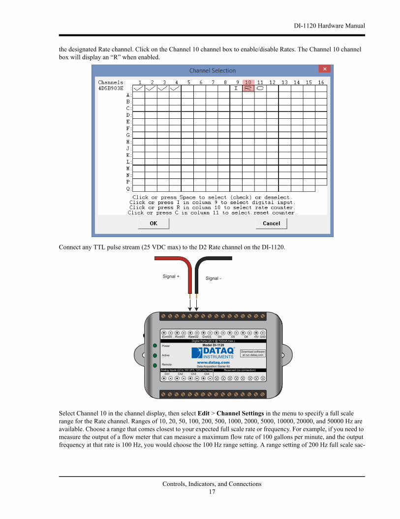
WINDAQ Rate (Rate/D2)Enable channel 10 to record Rate, or the number of falling-edge transitions per unit of time that are applied to this input. Click on Edit > Channels in the WINDAQ Acquisition menu to open the Channel Selection grid. Channel 10 is
Signal + Signal -
www.dataq.com
+ - + -+ -+ -D5D4 D6 GnD+5V
Power
Remote
Active
-+Ch1
-+Ch2
-+Ch3
-+Ch4
Model DI-1120
Reserved (no connection)Analog Inputs (±2 to 100 VFS, 120V rms max)
+ - + -+ -+ -Digital Ports (25 V @ 100mA max.)
Data Acquisition Starter Kit
Download software
at run.dataq.com
Rate/D2 Cnt/D3Rcrd/D1Evnt/D0
Controls, Indicators, and Connections16
DI-1120 Hardware Manual
the designated Rate channel. Click on the Channel 10 channel box to enable/disable Rates. The Channel 10 channel box will display an “R” when enabled.
Connect any TTL pulse stream (25 VDC max) to the D2 Rate channel on the DI-1120.
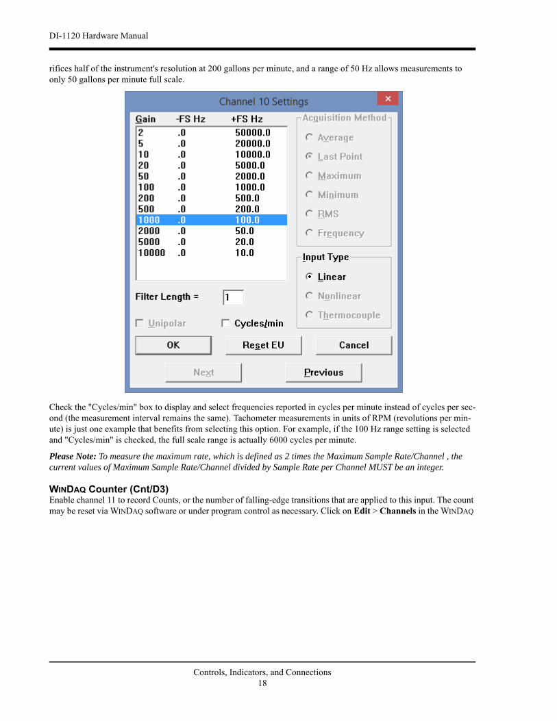
Select Channel 10 in the channel display, then select Edit > Channel Settings in the menu to specify a full scale range for the Rate channel. Ranges of 10, 20, 50, 100, 200, 500, 1000, 2000, 5000, 10000, 20000, and 50000 Hz are available. Choose a range that comes closest to your expected full scale rate or frequency. For example, if you need to measure the output of a flow meter that can measure a maximum flow rate of 100 gallons per minute, and the output frequency at that rate is 100 Hz, you would choose the 100 Hz range setting. A range setting of 200 Hz full scale sac-
Signal + Signal -
www.dataq.com
+ - + -+ -+ -D5D4 D6 GnD+5V
Power
Remote
Active
-+Ch1
-+Ch2
-+Ch3
-+Ch4
Model DI-1120
Reserved (no connection)Analog Inputs (±2 to 100 VFS, 120V rms max)
+ - + -+ -+ -Digital Ports (25 V @ 100mA max.)
Data Acquisition Starter Kit
Download software
at run.dataq.com
Rate/D2 Cnt/D3Rcrd/D1Evnt/D0
Controls, Indicators, and Connections17
DI-1120 Hardware Manual
rifices half of the instrument's resolution at 200 gallons per minute, and a range of 50 Hz allows measurements to only 50 gallons per minute full scale.
Check the "Cycles/min" box to display and select frequencies reported in cycles per minute instead of cycles per sec-ond (the measurement interval remains the same). Tachometer measurements in units of RPM (revolutions per min-ute) is just one example that benefits from selecting this option. For example, if the 100 Hz range setting is selected and "Cycles/min" is checked, the full scale range is actually 6000 cycles per minute.
Please Note: To measure the maximum rate, which is defined as 2 times the Maximum Sample Rate/Channel , the current values of Maximum Sample Rate/Channel divided by Sample Rate per Channel MUST be an integer.
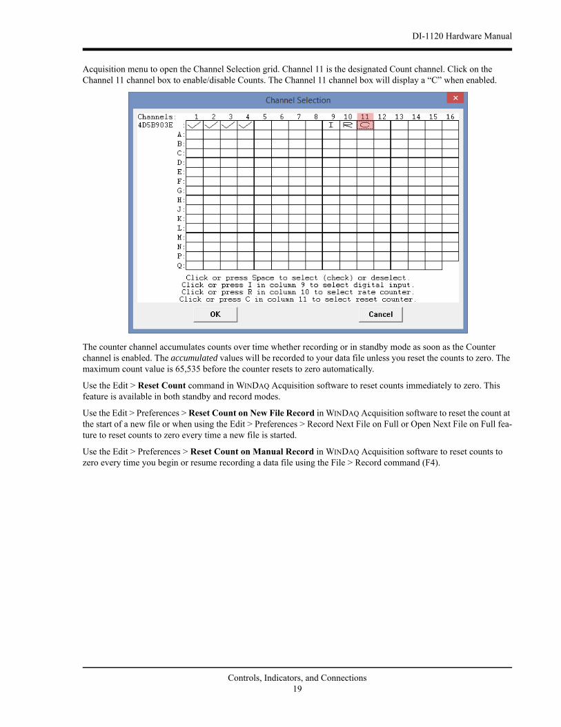
WINDAQ Counter (Cnt/D3)Enable channel 11 to record Counts, or the number of falling-edge transitions that are applied to this input. The count may be reset via WINDAQ software or under program control as necessary. Click on Edit > Channels in the WINDAQ
Controls, Indicators, and Connections18
DI-1120 Hardware Manual
Acquisition menu to open the Channel Selection grid. Channel 11 is the designated Count channel. Click on the Channel 11 channel box to enable/disable Counts. The Channel 11 channel box will display a “C” when enabled.
The counter channel accumulates counts over time whether recording or in standby mode as soon as the Counter channel is enabled. The accumulated values will be recorded to your data file unless you reset the counts to zero. The maximum count value is 65,535 before the counter resets to zero automatically.
Use the Edit > Reset Count command in WINDAQ Acquisition software to reset counts immediately to zero. This feature is available in both standby and record modes.
Use the Edit > Preferences > Reset Count on New File Record in WINDAQ Acquisition software to reset the count at the start of a new file or when using the Edit > Preferences > Record Next File on Full or Open Next File on Full fea-ture to reset counts to zero every time a new file is started.
Use the Edit > Preferences > Reset Count on Manual Record in WINDAQ Acquisition software to reset counts to zero every time you begin or resume recording a data file using the File > Record command (F4).
Controls, Indicators, and Connections19
DI-1120 Hardware Manual
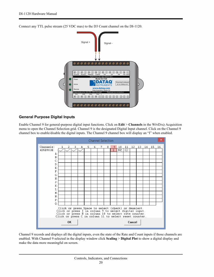
Connect any TTL pulse stream (25 VDC max) to the D3 Count channel on the DI-1120.
General Purpose Digital Inputs
Enable Channel 9 for general-purpose digital input functions. Click on Edit > Channels in the WINDAQ Acquisition menu to open the Channel Selection grid. Channel 9 is the designated Digital Input channel. Click on the Channel 9 channel box to enable/disable the digital inputs. The Channel 9 channel box will display an “I” when enabled.
Channel 9 records and displays all the digital inputs, even the state of the Rate and Count inputs if those channels are enabled. With Channel 9 selected in the display window click Scaling > Digital Plot to show a digital display and make the data more meaningful on screen.
Signal + Signal -
www.dataq.com
+ - + -+ -+ -D5D4 D6 GnD+5V
Power
Remote
Active
-+Ch1
-+Ch2
-+Ch3
-+Ch4
Model DI-1120
Reserved (no connection)Analog Inputs (±2 to 100 VFS, 120V rms max)
+ - + -+ -+ -Digital Ports (25 V @ 100mA max.)
Data Acquisition Starter Kit
Download software
at run.dataq.com
Rate/D2 Cnt/D3Rcrd/D1Evnt/D0
Controls, Indicators, and Connections20
DI-1120 Hardware Manual
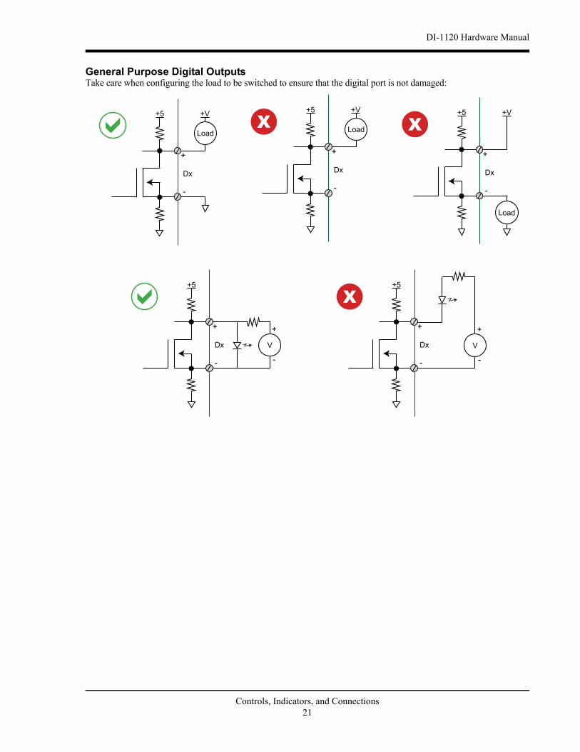
General Purpose Digital OutputsTake care when configuring the load to be switched to ensure that the digital port is not damaged:
Dx
+5 +V
Dx
+5 +V
Dx
+5 +V
Dx
+5
Dx
+5
Controls, Indicators, and Connections21
DI-1120 Hardware Manual
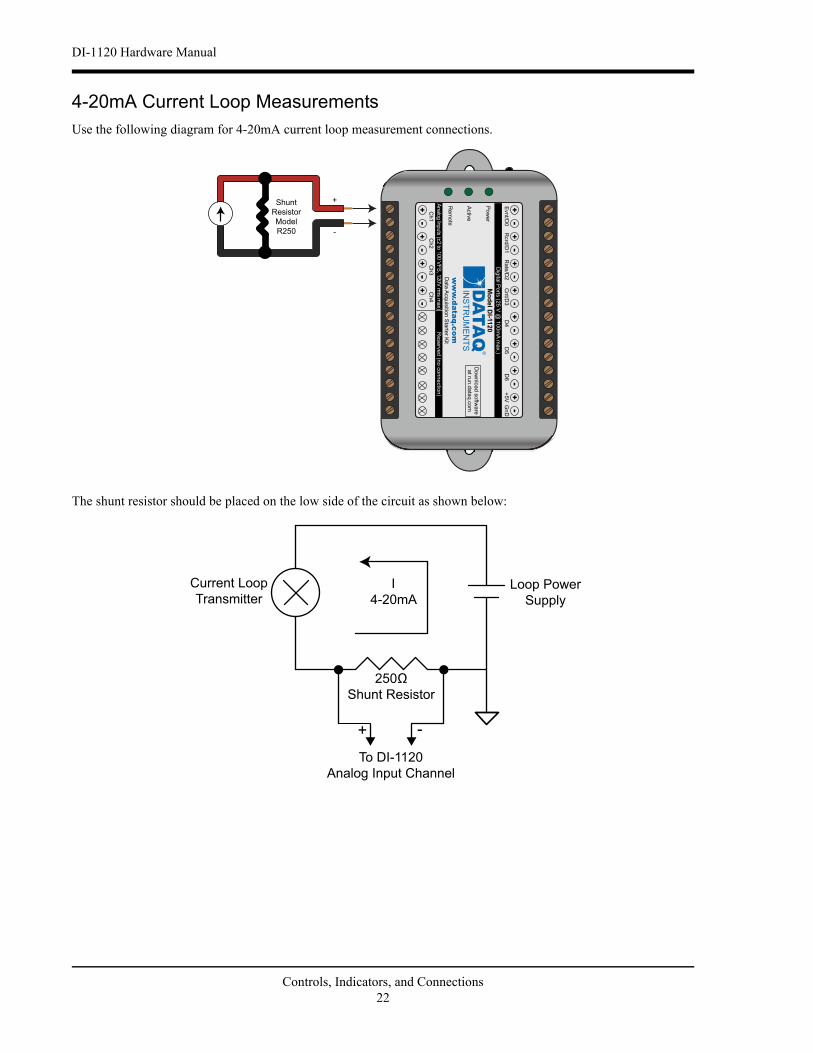
4-20mA Current Loop MeasurementsUse the following diagram for 4-20mA current loop measurement connections.
The shunt resistor should be placed on the low side of the circuit as shown below:
www.dataq.com
+-
+-
+-
+-
D5
D4
D6
GnD
+5V
Pow
er
Rem
ote
Activ
e-+
Ch1
-+
Ch2
-+
Ch3
-+
Ch4
Model D
I-1120
Reserv
ed (n
o c
onnectio
n)
Analo
g In
puts
(±2 to
100 V
FS
, 120V
rms m
ax)
+-
+-
+-
+-
Dig
ital P
orts
(25 V
@ 1
00m
A m
ax.)
Data
Acquis
ition S
tarte
r Kit
Dow
nlo
ad s
oftw
are
at ru
n.d
ata
q.c
om
Rate
/D2
Cnt/D
3R
crd
/D1
Evnt/D
0
Shunt
Resistor
Model
R250
+
-
Shunt Resistor
I
4-20mA
Current Loop
TransmitterLoop Power
Supply
To DI-1120
Analog Input Channel
+ -
Controls, Indicators, and Connections22
DI-1120 Hardware Manual
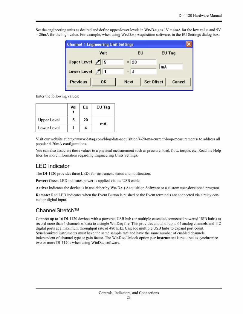
Set the engineering units as desired and define upper/lower levels in WINDAQ as 1V = 4mA for the low value and 5V = 20mA for the high value. For example, when using WINDAQ Acquisition software, in the EU Settings dialog box:
Enter the following values:
Visit our website at http://www.dataq.com/blog/data-acquisition/4-20-ma-current-loop-measurements/ to address all popular 4-20mA configurations.
You can also associate these values to a physical measurement such as pressure, load, flow, torque, etc. Read the Help files for more information regarding Engineering Units Settings.
LED IndicatorThe DI-1120 provides three LEDs for instrument status and notification.
Power: Green LED indicates power is applied via the USB cable.
Active: Indicates the device is in use either by WINDAQ Acquisition Software or a custom user-developed program.
Remote: Red LED indicates when the Event Button is pushed or the Event terminals are connected via a relay con-tact or digital input.
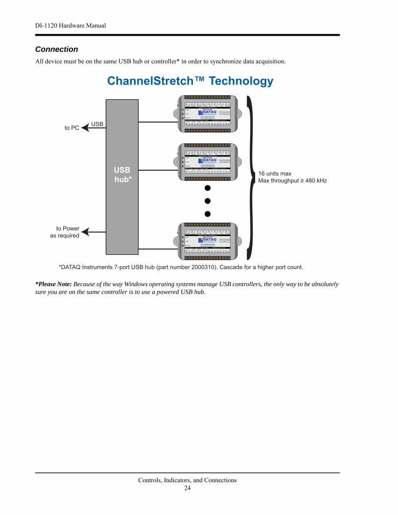
ChannelStretch™Connect up to 16 DI-1120 devices with a powered USB hub (or multiple cascaded/connected powered USB hubs) to record more than 4 channels of data to a single WinDaq file. This provides a total of up to 64 analog channels and 112 digital ports at a maximum throughput rate of 480 kHz. Cascade multiple USB hubs to expand port count. Synchronized instruments must have the same sample rate and have the same number of enabled channels independent of channel type or gain factor. The WinDaq/Unlock option per instrument is required to synchronize two or more DI-1120s when using WinDaq software.
All device must be on the same USB hub or controller* in order to synchronize data acquisition.
*Please Note: Because of the way Windows operating systems manage USB controllers, the only way to be absolutely sure you are on the same controller is to use a powered USB hub.
USBto PC
to Power
as required
*DATAQ Instruments 7-port USB hub (part number 2000310). Cascade for a higher port count.
USB hub*
16 units max
ChannelStretch™ Technology
www.dataq.com
+ - + -+ -+ -D5 D6 GnD+5V
Power
Remote
Active
-+Ch1
-+Ch2
-+Ch3
-+
Model DI-1120
Reserved (no connection)Analog Inputs (±2 to 100 VFS, 120V rms max)
+ - + -+ -+ -Digital Ports (25 V @ 100mA max.)
Data Acquisition Starter Kit
Download software
at run.dataq.com
Rate/D2 Cnt/D3Rcrd/D1Evnt/D0
Controls, Indicators, and Connections24
DI-1120 Hardware Manual
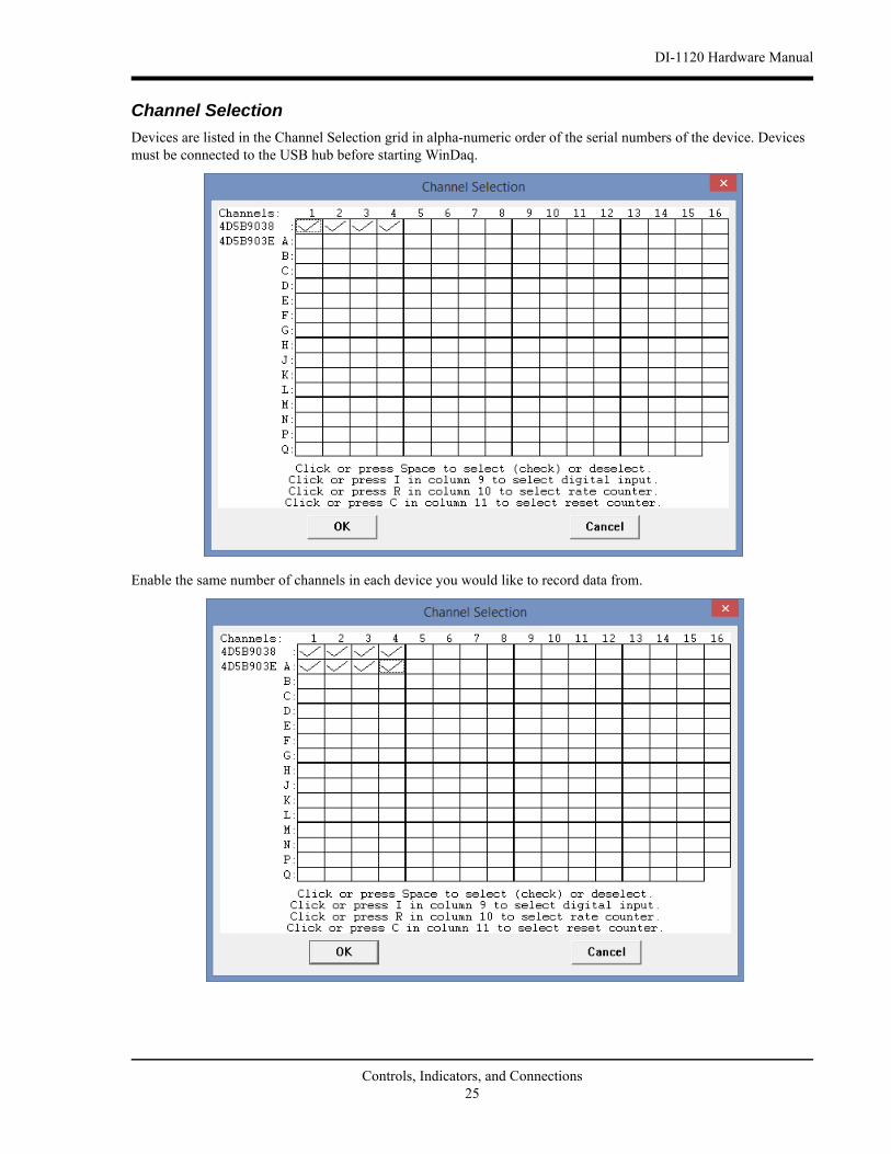
Channel Selection
Devices are listed in the Channel Selection grid in alpha-numeric order of the serial numbers of the device. Devices must be connected to the USB hub before starting WinDaq.
Enable the same number of channels in each device you would like to record data from.