Page 1
Me
mb
er
of th
e H
elm
ho
ltz A
sso
cia
tio
n
Diagnostics and control of fusion plasmas
W. Biel1,2
1Institute of Energy- and Climate Research, Forschungszentrum Jülich GmbH, Germany
2Department of Applied Physics, Ghent University, Belgium
DPG School “The Physics of ITER”
Bad Honnef, 26.09.2014
Page 2
Wolfgang Biel | Diagnostics and control of fusion plasmas | DPG school „The physics of ITER“ 26 Sept 2014 No 2
Plasma diagnostics
Measurement means comparison …
… but how to perform measurements in a hot fusion plasma?
Page 3
Wolfgang Biel | Diagnostics and control of fusion plasmas | DPG school „The physics of ITER“ 26 Sept 2014 No 3
Plasma diagnostics
Measurement means comparison …
50 million degrees
Page 4
Wolfgang Biel | Diagnostics and control of fusion plasmas | DPG school „The physics of ITER“ 26 Sept 2014 No 4
Measurements in a fusion plasma
plasma
first wall measurement
principle
sensor data
aquisition
… are generally performed in an indirect way …
analysis
Page 5
Wolfgang Biel | Diagnostics and control of fusion plasmas | DPG school „The physics of ITER“ 26 Sept 2014 No 5
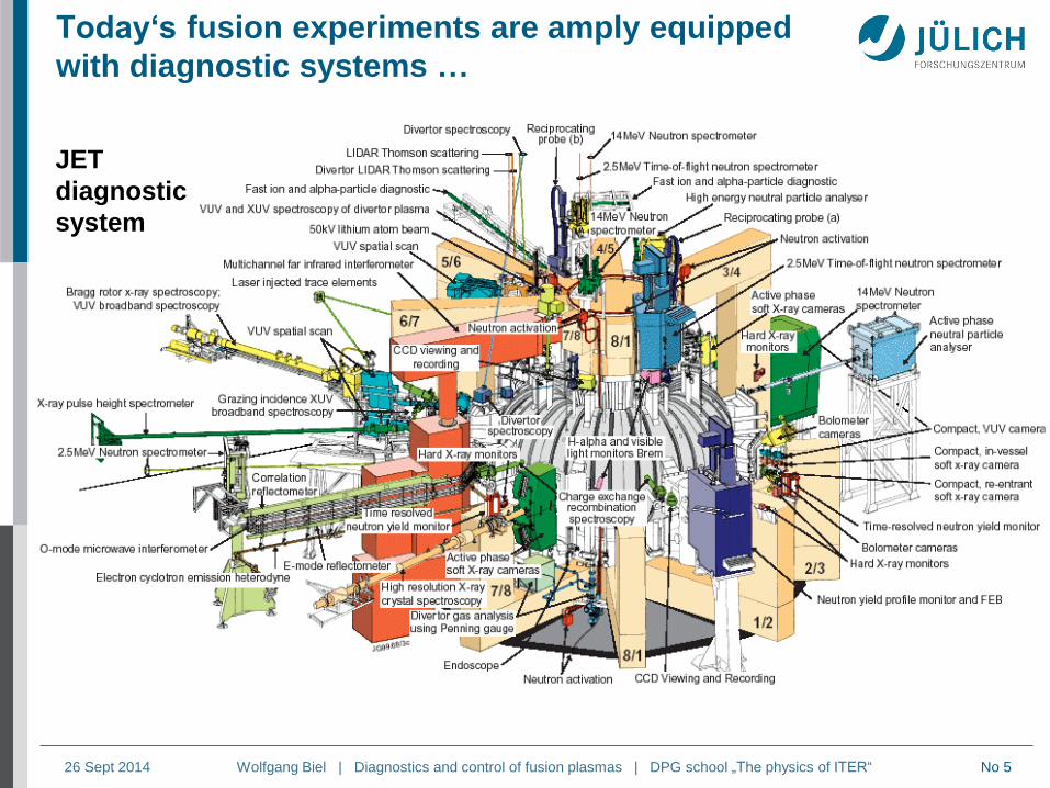
Today‘s fusion experiments are amply equipped
with diagnostic systems …
JET
diagnostic
system
Page 6
Wolfgang Biel | Diagnostics and control of fusion plasmas | DPG school „The physics of ITER“ 26 Sept 2014 No 6
Integrated plasma diagnostics processing & control
actuator commands Tokamak
state
measurements
[Real-time control]
Plasma
controller
Plasma state
reconstruction
abnormal meas.
Fault
detection
state
Controller Observer
Supervision
Plasma controller: perform control actions based on full plasma state knowledge
Plasma state reconstruction: derive plasma state by merging measurements
from several diagnostics
Fault detection: classify unexpected measurements (e.g. off-normal events,
faulty signals)
Diagnostic redundancy in number of channels and number of methods facilitates
handling of faults (the better the model, the less measurements are needed)
(F. Felici, M. de Baar)
Page 7
Wolfgang Biel | Diagnostics and control of fusion plasmas | DPG school „The physics of ITER“ 26 Sept 2014 No 7
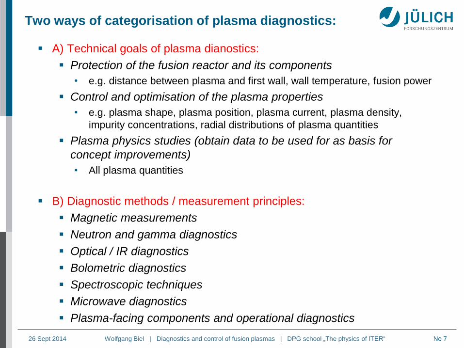
Two ways of categorisation of plasma diagnostics:
A) Technical goals of plasma dianostics:
Protection of the fusion reactor and its components
• e.g. distance between plasma and first wall, wall temperature, fusion power
Control and optimisation of the plasma properties
• e.g. plasma shape, plasma position, plasma current, plasma density,
impurity concentrations, radial distributions of plasma quantities
Plasma physics studies (obtain data to be used for as basis for
concept improvements)
• All plasma quantities
B) Diagnostic methods / measurement principles:
Magnetic measurements
Neutron and gamma diagnostics
Optical / IR diagnostics
Bolometric diagnostics
Spectroscopic techniques
Microwave diagnostics
Plasma-facing components and operational diagnostics
Page 8
Wolfgang Biel | Diagnostics and control of fusion plasmas | DPG school „The physics of ITER“ 26 Sept 2014 No 8
UPPER PORT
(10 used)
EQUATORIAL PORT
(6 used)
Main Boundary
DIVERTOR (3 used)
VESSEL WALL
(Distributed Systems)
ITER: Diagnostic Implementation Scheme
(P. Thomas, ITER)
Page 9
Wolfgang Biel | Diagnostics and control of fusion plasmas | DPG school „The physics of ITER“ 26 Sept 2014 No 9
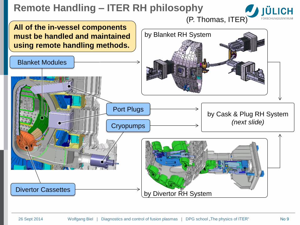
All of the in-vessel components
must be handled and maintained
using remote handling methods.
by Blanket RH System
by Divertor RH System
by Cask & Plug RH System
(next slide)
Divertor Cassettes
Port Plugs
Cryopumps
Blanket Modules
Remote Handling – ITER RH philosophy (P. Thomas, ITER)
Page 10
Wolfgang Biel | Diagnostics and control of fusion plasmas | DPG school „The physics of ITER“ 26 Sept 2014 No 10
Port-Plugs - Integration of Equatorial 11 Port Plug
PP ISS BS PCSS1 PCSS2
Interspace (ISS) Port Cell structures (PCSS)
• Lot of back-end
equipment that must be
removed before port-plug
movement.
3m Low field side Reflectometry (US)
Neutral Particle Analyser (RF)
H-alpha and Visible Spectroscopy (RF)
X-Ray Crystal Spectroscopy-Survey (IN)
Divertor Vacuum Ultraviolet (KO)
Residual Gas Analyser (US)
VUV – Main Plasma (KO)
Neutron Activation System, foil, 1 of 2 (KO)
(P. Thomas, ITER)
Page 11
Wolfgang Biel | Diagnostics and control of fusion plasmas | DPG school „The physics of ITER“ 26 Sept 2014 No 11
ITER diagnostics distribution
Page 12
Wolfgang Biel | Diagnostics and control of fusion plasmas | DPG school „The physics of ITER“ 26 Sept 2014 No 12
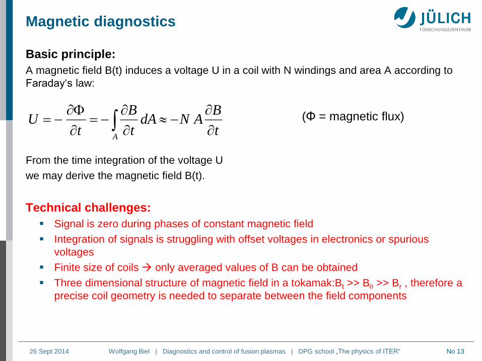
Basic principle:
A magnetic field B(t) induces a voltage U in a coil with N windings and area A according to
Faraday‘s law:
From the time integration of the voltage U
we may derive the magnetic field B(t):
Magnetic diagnostics
At
BANdA
t
B
tU
U U0
00
0 BtBCR
ANdt
t
B
CR
ANU
t
Page 13
Wolfgang Biel | Diagnostics and control of fusion plasmas | DPG school „The physics of ITER“ 26 Sept 2014 No 13
Basic principle:
A magnetic field B(t) induces a voltage U in a coil with N windings and area A according to
Faraday‘s law:
From the time integration of the voltage U
we may derive the magnetic field B(t).
Technical challenges:
Signal is zero during phases of constant magnetic field
Integration of signals is struggling with offset voltages in electronics or spurious
voltages
Finite size of coils only averaged values of B can be obtained
Three dimensional structure of magnetic field in a tokamak:Bt >> B >> Br , therefore a
precise coil geometry is needed to separate between the field components
Magnetic diagnostics
At
BANdA
t
B
tU (Φ = magnetic flux)
Page 14
Wolfgang Biel | Diagnostics and control of fusion plasmas | DPG school „The physics of ITER“ 26 Sept 2014 No 14
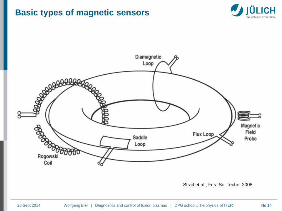
Basic types of magnetic sensors
Strait et al., Fus. Sc. Techn. 2008
Page 15
Wolfgang Biel | Diagnostics and control of fusion plasmas | DPG school „The physics of ITER“ 26 Sept 2014 No 15
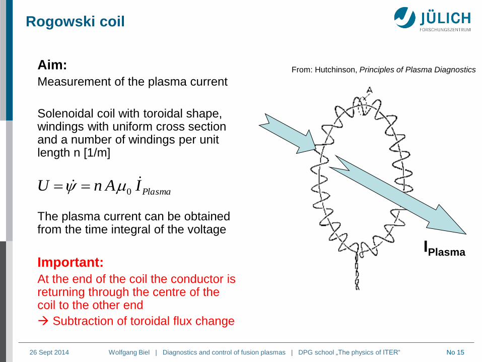
Rogowski coil
Aim:
Measurement of the plasma current
Solenoidal coil with toroidal shape, windings with uniform cross section and a number of windings per unit length n [1/m]
The plasma current can be obtained from the time integral of the voltage
Important:
At the end of the coil the conductor is returning through the centre of the coil to the other end
Subtraction of toroidal flux change
From: Hutchinson, Principles of Plasma Diagnostics
IPlasma
PlasmaIAnU 0
Page 16
Wolfgang Biel | Diagnostics and control of fusion plasmas | DPG school „The physics of ITER“ 26 Sept 2014 No 16
Outer ITER Rogowski coil
Cross section
Overall layout
(2 segments)
1
Weld
Hold-down strip
(Length: TBD)
Gap (Length: TBD)
12 mm DIA
CER
14 mm wide groove
TFC Case
Fiber glass strip
(for cooling pipes
only) Coil mounted in a groove
at the TF coil casing
Page 17
Wolfgang Biel | Diagnostics and control of fusion plasmas | DPG school „The physics of ITER“ 26 Sept 2014 No 17
Measurement of plasma position
The plasma position can be determined via the measurement of the fourier
components of the poloidal magnetic field:
Cosine coil for horizontal position
Sine coil for vertical position (not shown)
The measured time integrated signal is
proportional to the plasma dislocation
Alternative approach:
Use discrete coils and perform numeric analysis
for plasma position.
winding density
varies ~ cos
after: Hutchinson, Principles of Plasma Diagnostics
sincos1
2
0
aaa
IB VH
inversion of the
winding direction
Page 18
Wolfgang Biel | Diagnostics and control of fusion plasmas | DPG school „The physics of ITER“ 26 Sept 2014 No 18
Ohmic heating power and electrical conductivity
The toroidal loop voltage generated from
the transformer is driving the (ohmic part
of the) plasma current:
In the stationary plasma phase,
the loop voltage depends on the
electrical conductivity of the
plasma
If the electron temperature Te is
known, we can derive the effective
ion charge Zeff from the loop
voltage.
Ohmic heating power:
PW = Ip x Uloop
]mΩ[
1
]eV[ln
185121092.1
2
31
2
0
2
0
3
1
4
e
eff
eff
kT
ZR
a
R
aZ
Page 19
Wolfgang Biel | Diagnostics and control of fusion plasmas | DPG school „The physics of ITER“ 26 Sept 2014 No 19
Energy content of the plasma
Define the energy confinement time
The energy confinement time can be determined from the measurement of the
loss power (in the stationary case ~ heating power), the particle densities and
temperatures)
In a plasma with various ion species and impurities the measurement of all
densities and temperatures is a complex task.
Alternatively, the kinetic plasma energy WPlasma can be determined via the
measurement of the change of toroidal flux:
loss
k
kBkplasma
loss
plasma
EP
TknV
P
W
2
3
(summation over all particle species k)
tortorPlasma
RBIR
I
BIRW
0
002
0022
0
02
00
3
8
381
8
3
(inductive) (kinetic)
(Assumption:
circular plasma
cross section)
Page 20
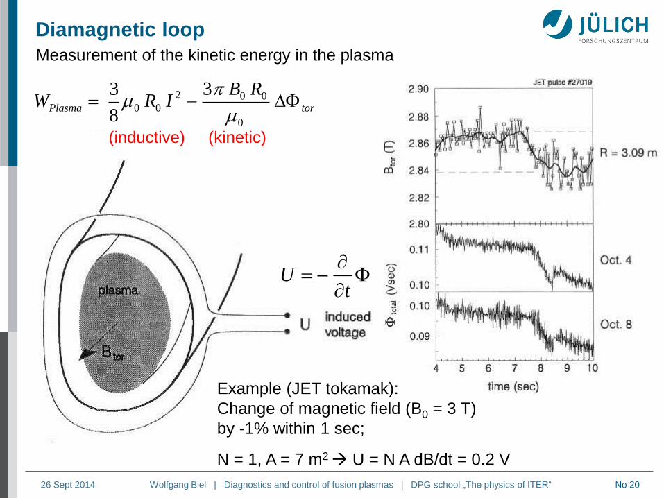
Wolfgang Biel | Diagnostics and control of fusion plasmas | DPG school „The physics of ITER“ 26 Sept 2014 No 20
Diamagnetic loop
tU
Example (JET tokamak):
Change of magnetic field (B0 = 3 T)
by -1% within 1 sec;
N = 1, A = 7 m2 U = N A dB/dt = 0.2 V
Measurement of the kinetic energy in the plasma
torPlasma
RBIRW
0
002
00
3
8
3
(inductive) (kinetic)
Page 21
Wolfgang Biel | Diagnostics and control of fusion plasmas | DPG school „The physics of ITER“ 26 Sept 2014 No 21
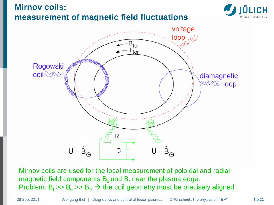
Mirnov coils:
measurement of magnetic field fluctuations
Mirnov coils are used for the local measurement of poloidal and radial
magnetic field components B und Br near the plasma edge.
Problem: Bt >> B >> Br, the coil geometry must be precisely aligned
.
Page 22
Wolfgang Biel | Diagnostics and control of fusion plasmas | DPG school „The physics of ITER“ 26 Sept 2014 No 22
Magnetic diagnostic: Mirnov coils
Examples for the technical realisation:
Micro Mirnov coil (MAST)
Mirnov coils on TEXTOR
Page 23
Wolfgang Biel | Diagnostics and control of fusion plasmas | DPG school „The physics of ITER“ 26 Sept 2014 No 23
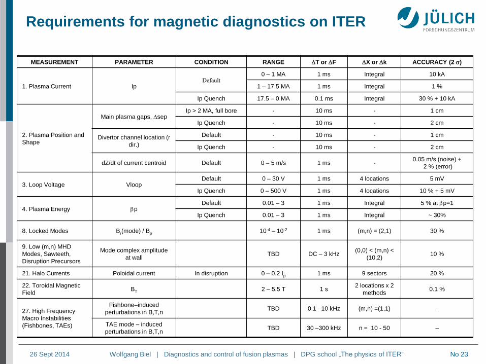
Requirements for magnetic diagnostics on ITER
MEASUREMENT PARAMETER CONDITION RANGE T or F X or k ACCURACY (2 )
1. Plasma Current Ip Default
0 – 1 MA 1 ms Integral 10 kA
1 – 17.5 MA 1 ms Integral 1 %
Ip Quench 17.5 – 0 MA 0.1 ms Integral 30 % + 10 kA
2. Plasma Position and
Shape
Main plasma gaps, sep Ip > 2 MA, full bore - 10 ms - 1 cm
Ip Quench - 10 ms - 2 cm
Divertor channel location (r
dir.)
Default - 10 ms - 1 cm
Ip Quench - 10 ms - 2 cm
dZ/dt of current centroid Default 0 – 5 m/s 1 ms - 0.05 m/s (noise) +
2 % (error)
3. Loop Voltage Vloop Default 0 – 30 V 1 ms 4 locations 5 mV
Ip Quench 0 – 500 V 1 ms 4 locations 10 % + 5 mV
4. Plasma Energy bp Default 0.01 – 3 1 ms Integral 5 % at bp=1
Ip Quench 0.01 – 3 1 ms Integral ~ 30%
8. Locked Modes Br(mode) / Bp 10-4 – 10-2 1 ms (m,n) = (2,1) 30 %
9. Low (m,n) MHD
Modes, Sawteeth,
Disruption Precursors
Mode complex amplitude
at wall TBD DC – 3 kHz
(0,0) < (m,n) <
(10,2) 10 %
21. Halo Currents Poloidal current In disruption 0 – 0.2 Ip 1 ms 9 sectors 20 %
22. Toroidal Magnetic
Field BT 2 – 5.5 T 1 s
2 locations x 2
methods 0.1 %
27. High Frequency
Macro Instabilities
(Fishbones, TAEs)
Fishbone–induced
perturbations in B,T,n TBD 0.1 –10 kHz (m,n) =(1,1) –
TAE mode – induced
perturbations in B,T,n TBD 30 –300 kHz n = 10 - 50 –
Page 24
Wolfgang Biel | Diagnostics and control of fusion plasmas | DPG school „The physics of ITER“ 26 Sept 2014 No 24
Radiation effects on diagnostics + actuators
Effect Symbol Explanation
Radiation-induced
conductivity RIC
Electrical conductivity increases due to the excitation of electrons
into the conduction band.
Radiation-induced
electrical degradation RIED
Electrical conductivity increases due to radiation and electric field
enhanced defect aggregation.
Thermal conductivity
decrease – Thermal conductivity decreases leading to temperature increases.
Volume changes – Materials swell, or in some cases shrink
Radiation-Induced
Electromotive Force RIEMF
Nuclear reactions in the sensor materials induce net current in the
sensor circuit
Thermoelectric
Electromotive Force TIEMF Parasitic thermocouple action driven by nuclear-heating
Radiation-induced
thermoelectric
sensitivity
RITES Additional parasitic thermocouples generated by non-uniform
material damage and transmutation
Radiation-enhanced
diffusion –
Enhanced diffusion occurs in insulating materials due to the possible
existence of different charge states for defects and impurities.
Radiation-induced
absorption RIA
Optical absorption increases due to the production of defect related
absorption bands, leading to light transmission loss.
Radioluminescence
or radiation-induced
emission
RL or RIE Light emission due to excitation of defects and impurities.
(after G. Vayakis, ITER organisation)
Page 25
Wolfgang Biel | Diagnostics and control of fusion plasmas | DPG school „The physics of ITER“ 26 Sept 2014 No 25
Where are magnetics mounted? (G. Vayakis, ITER)
• On the divertor
(most exposed)
• Just behind the
ITER blanket in
vessel
• On the outer vessel
skin
• Inside the TF coil
(least exposed)
Note: backward mounting results in longer lifetime of components but reduced
performance due to signal attenuation and shielding by eddy currents
Page 26
Wolfgang Biel | Diagnostics and control of fusion plasmas | DPG school „The physics of ITER“ 26 Sept 2014 No 26
Wave propagation in plasmas
Most basic case: cold plasma without magnetic field
( = angular frequency; N = refractive index)
where the plasma frequency is given by
In this most basic case any electromagnetic wave with frequency below the plasma
frequency cannot penetrate into the plasma the wave will be reflected „reflectometry“
Example:
For an electron density ne = 1020m-3 we obtain P = 5.6 x 10¹¹s-1, f = P / 2 = 90 GHz
this translates to a wavelength of = c / f = 3.34 mm (microwave range)
Wave with frequencies above the plasma frequency can penetrate into the plasma, but
they experience a phase shift (N < 1).
2
2222 1;
P
P Nck
(this is the oscillation frequency of the electron fluid if
the electrons are displaced against the ion background)
e
ePm
en
0
2
Page 27
Wolfgang Biel | Diagnostics and control of fusion plasmas | DPG school „The physics of ITER“ 26 Sept 2014 No 27
Plasma interferometry
• The refractive index N of a
plasma depends on the
electron density and on the
wavelength
• The interferometer measures
the phase shift due to the
plasma (phase angle )
Interferometry: measurement of electron density integrated along
the sightline
laser
detector plasma
e
ePP
m
enN
0
22
,1
Page 28
Wolfgang Biel | Diagnostics and control of fusion plasmas | DPG school „The physics of ITER“ 26 Sept 2014 No 28
HCN interferometer on TEXTOR
R/m
1 2 3 4 5 6 7 8 9 z
1,75 1,85 1,95 2,05 2,15 1,65 1,57 1,44
arrangement of 9 channels
(only 1 channel shown)
Page 29
Wolfgang Biel | Diagnostics and control of fusion plasmas | DPG school „The physics of ITER“ 26 Sept 2014 No 29
Infrared polarimetry
Propagation of a laser beam in a plasma with electron density ne and
a magnetic field component BII oriented along the beam
rotation the beam polarisation (= Faraday rotation):
Z = coordinate along BII
= laser wavelength [m]
ne = electron density [m-3]
BII = magnetic field component along the beam [T]
Example: = 10 µm, Z1-Z0 = 10 m, BII = 5 T, ne = 1020 m-3 𝛥𝜃 = 0.113
𝛥𝜃 = 2.62 × 10⁻¹³𝜆2 𝑛𝑒𝐵∥d𝑍𝑍1
𝑍0
Page 30
Wolfgang Biel | Diagnostics and control of fusion plasmas | DPG school „The physics of ITER“ 26 Sept 2014 No 30
Current density measurement in a tokamak via
polarimetry H. Soltwisch, Rev. Sci. Instrum. 1986
The current density in a tokamak is stronger peaked
than expected q < 1 in the plasma centre possible
Page 31
Wolfgang Biel | Diagnostics and control of fusion plasmas | DPG school „The physics of ITER“ 26 Sept 2014 No 31
Tangential and poloidal I/P systems in ITER
Interferometer:
max. phase: ~ 10 fringes
polarimetry
max. phase: << 1 fringe
(M. A. van Zeeland, Rev. Sci. Instrum, 2013)
Polarimetry data analysis has to take into
account:
• Faraday effect (B II beam)
• Cotton-Mouton (C-M) effect (B beam)
• Temperature dependence of rotation
angle and relativistic effects
V.V. Mirnov et al.
Varenna Conf. 2013
Page 32
Wolfgang Biel | Diagnostics and control of fusion plasmas | DPG school „The physics of ITER“ 26 Sept 2014 No 32
Measurement of electron cyclotron emission (ECE)
to determine the electron temperature
Electrons and ions gyrate around the magnetic field lines centrifugal forces
Classical electrodynamics:
Accelerated charged particles emit electromagnetic radiation
The frequency of the ECE radiation is the gyration frequency ce (and in principle also ci)
and their higher harmonics nce (and nci), with n = 2, 3, …
In a fusion plasma the radiation at the fundament frequency ce is optically thick.
The emitted photons will be absorbed and re-emitted several times in the plasma.
ECE is black-body radiation
B
Electron
e
cem
eB
Page 33
Wolfgang Biel | Diagnostics and control of fusion plasmas | DPG school „The physics of ITER“ 26 Sept 2014 No 33
Determination of the electron temperature Te from
ECE measurements
Optically thick radiation can be described by a Planck curve:
1exp
1
8)(
23
3
eBTk
cB
The electron temperature can
be determined from an
intensity measurement
Page 34
Wolfgang Biel | Diagnostics and control of fusion plasmas | DPG school „The physics of ITER“ 26 Sept 2014 No 34
In a fusion plasma with magnetic field the gyrating electrons radiate at the
cyclotron frequency and at their higher harmonics.
Apply the low frequency approximation:
In this case the Planck curve
simplifies towards the Rayleigh-Jeans law:
The measured ECE intensity is proportional to the electron temperature.
The ECE diagnostic needs an intensity calibration.
1exp
1
8)(
23
3
eBTk
cB
Analysis of ECE measurements
ece m
eB
kTe kT
1
23
2
8)(
c
TkB eB
Page 35
Wolfgang Biel | Diagnostics and control of fusion plasmas | DPG school „The physics of ITER“ 26 Sept 2014 No 35
Radial dependence of frequencies for microwave
diagnostics on a DEMO reactor
e
cem
eB
R
RBRB ;)( 00
(A. Silva et al.)
Page 36
Wolfgang Biel | Diagnostics and control of fusion plasmas | DPG school „The physics of ITER“ 26 Sept 2014 No 36
ECE measurement: necessary corrections
1. Relativistic correction: For high electron temperatures, the relativistic
dependence of the mass has to be considered:
For a given frequency, the actual place of measurement is shifting
towards the high field side of the torus, i.e. to lower values of R
2. Diamagnetic correction: The sum of kinetic plasma pressure and
magnetic pressure is constant:
Again, for a given frequency, the actual place of measurement is shifting
towards the high field side of the torus, i.e. to lower values of R
e
cem
eB 1
v1
1
2
2
c
0
2
0
0
2
22
Bconst
Bp
Page 37
Wolfgang Biel | Diagnostics and control of fusion plasmas | DPG school „The physics of ITER“ 26 Sept 2014 No 37
KSTAR ECE System : 110-196 GHz
164-196 GHz
110-162 GHz
Overview of ECE Radiometer
Schematic of KSTAR ECE System
110 GHz Notch Filter
163 GHz Multiplexer
• Multiplexer Optics (2010-2012)
K. D. Lee and Seong-Heon Seo, NFRI (Korea)
Page 38
Wolfgang Biel | Diagnostics and control of fusion plasmas | DPG school „The physics of ITER“ 26 Sept 2014 No 38
R. Reichle (ITER), H. Meister (IPP)
Bolometry: Detector - principle
Page 39
Wolfgang Biel | Diagnostics and control of fusion plasmas | DPG school „The physics of ITER“ 26 Sept 2014 No 39
The diagnostic is the most important contributor to the measurement of
the total radiated power [ H. Meister , IPP Garching, Ringberg seminar 18.4.2013]
Spectral sensitivity range of bolometers
Page 40
Wolfgang Biel | Diagnostics and control of fusion plasmas | DPG school „The physics of ITER“ 26 Sept 2014 No 40
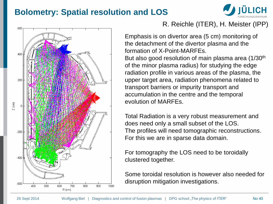
Emphasis is on divertor area (5 cm) monitoring of
the detachment of the divertor plasma and the
formation of X-Point-MARFEs.
But also good resolution of main plasma area (1/30th
of the minor plasma radius) for studying the edge
radiation profile in various areas of the plasma, the
upper target area, radiation phenomena related to
transport barriers or impurity transport and
accumulation in the centre and the temporal
evolution of MARFEs.
Total Radiation is a very robust measurement and
does need only a small subset of the LOS.
The profiles will need tomographic reconstructions.
For this we are in sparse data domain.
For tomography the LOS need to be toroidally
clustered together.
Some toroidal resolution is however also needed for
disruption mitigation investigations.
R. Reichle (ITER), H. Meister (IPP)
Bolometry: Spatial resolution and LOS
Page 41
Wolfgang Biel | Diagnostics and control of fusion plasmas | DPG school „The physics of ITER“ 26 Sept 2014 No 41
From the measured
Bremsstrahlung
background, the
electron temperature
and electron density
can be determined:
and
I ~ n2
Spectroscopy in the plasma core –
Pulse hight analysis SXR spectra in TFTR
Different filters
K. Hill et al.,
Rev. Sci. Instr.
1985
(low spectral resolution via measurement of charge pulses generated from photon
energies deposited in the semiconductor detector)
Page 42
Wolfgang Biel | Diagnostics and control of fusion plasmas | DPG school „The physics of ITER“ 26 Sept 2014 No 42
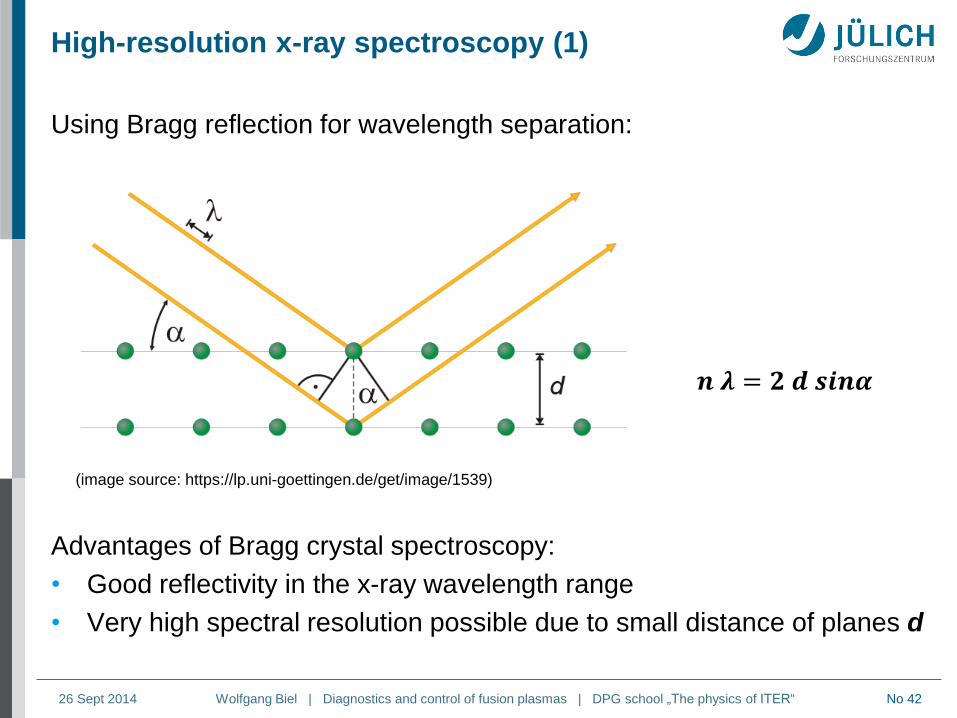
High-resolution x-ray spectroscopy (1)
Using Bragg reflection for wavelength separation:
Advantages of Bragg crystal spectroscopy:
• Good reflectivity in the x-ray wavelength range
• Very high spectral resolution possible due to small distance of planes d
(image source: https://lp.uni-goettingen.de/get/image/1539)
𝒏 𝝀 = 𝟐 𝒅 𝒔𝒊𝒏𝜶
Page 43
Wolfgang Biel | Diagnostics and control of fusion plasmas | DPG school „The physics of ITER“ 26 Sept 2014 No 43
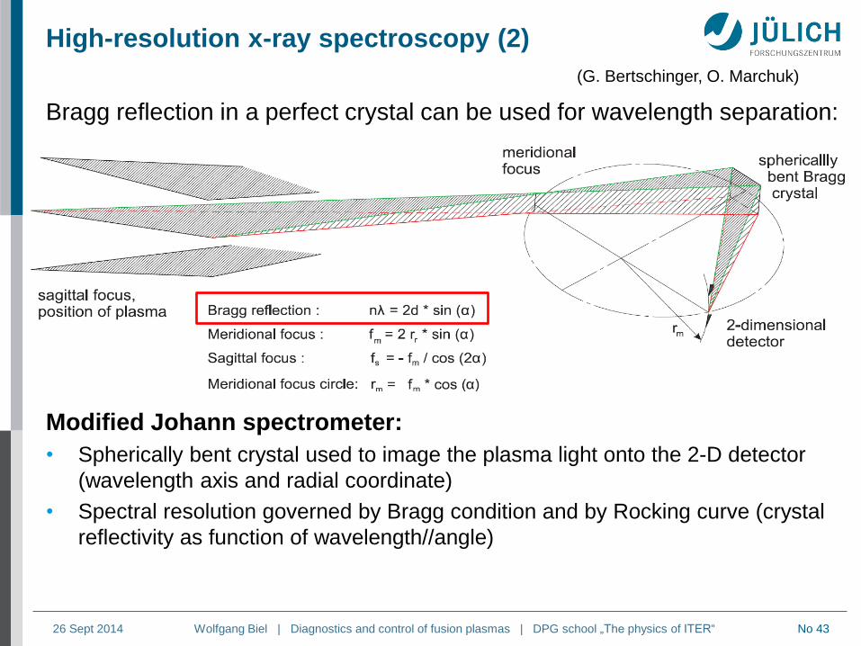
High-resolution x-ray spectroscopy (2)
Bragg reflection in a perfect crystal can be used for wavelength separation:
Modified Johann spectrometer:
• Spherically bent crystal used to image the plasma light onto the 2-D detector
(wavelength axis and radial coordinate)
• Spectral resolution governed by Bragg condition and by Rocking curve (crystal
reflectivity as function of wavelength//angle)
(G. Bertschinger, O. Marchuk)
Page 44
Wolfgang Biel | Diagnostics and control of fusion plasmas | DPG school „The physics of ITER“ 26 Sept 2014 No 44
Bragg spectrometer on TEXTOR / W7-X
Principle: Bragg spectometer on TEXTOR (2008):
(G. Bertschinger, O. Marchuk)
Page 45
Wolfgang Biel | Diagnostics and control of fusion plasmas | DPG school „The physics of ITER“ 26 Sept 2014 No 45
w line z line
Wavelength, Å
Example for x-ray spectra: He-like Argon (Ar16+)
• The He-like x-ray spectrum consists of several components, which
are excited via different processes
• The ion temperature can be derived from Doppler broadening
• The electron temperature can be obtained from line intensity ratios
(G. Bertschinger, O. Marchuk)
Page 46
Wolfgang Biel | Diagnostics and control of fusion plasmas | DPG school „The physics of ITER“ 26 Sept 2014 No 46
Charge exchange recombination spectroscopy
Process: AlnInAI zz ),()( *)1(
2
0 2ln8
w
B
ii
c
k
mTFWHM Ion temperature
0
v
rot
rot cLine shift: Rotation
dvnn beamembeamI Z
4
1integral Impurity density
Page 47
Wolfgang Biel | Diagnostics and control of fusion plasmas | DPG school „The physics of ITER“ 26 Sept 2014 No 47
Core CXRS diagnostic at JET
Page 48
Wolfgang Biel | Diagnostics and control of fusion plasmas | DPG school „The physics of ITER“ 26 Sept 2014 No 48 WS 2009/2010 48
ITER core CXRS diagnostics
Hydrogen Injector (100 keV)
CXRS spectrometers
CXRS port plug
with mirror labyrinth
….
Ph. Mertens, W. Biel, R. Jaspers, M. v. Hellermann, N. Hawkes, O. Marchuk et al.
Measurement of
nHe, Ti, vrot, Zeff,
nBe, B, D/T
*
2
)(
)(
HeEH
HeEH
Page 49
Wolfgang Biel | Diagnostics and control of fusion plasmas | DPG school „The physics of ITER“ 26 Sept 2014 No 49 WS 2009/2010 49
ITER CXRS: spectra modelling M. v. Hellermann et al.
low CXRS intensity
high background
Required accuracy for nHe: 10%
• atomic data
• absolute calibration
• statistical errors
Page 50
Wolfgang Biel | Diagnostics and control of fusion plasmas | DPG school „The physics of ITER“ 26 Sept 2014 No 50
Modelling of first mirror erosion and deposition
Neutral particle and ion fluxes for hydrogen isotopes and impurities
are modelled using the B2-EIRENE code package.
Principle geometry (with baffles):
(V. Kotov, FZJ)
(aperture)
(first mirror)
Page 51
Wolfgang Biel | Diagnostics and control of fusion plasmas | DPG school „The physics of ITER“ 26 Sept 2014 No 51
ITER core CXRS: development of a fast shutter
mirror 1 attachment with thermal
conditioning loops, shutter flaps
and alignment screws
shutter with
flaps and
actuator
Page 52
Wolfgang Biel | Diagnostics and control of fusion plasmas | DPG school „The physics of ITER“ 26 Sept 2014 No 52
Passive diagnostics: example of neutron detection w/o probing beams or lasers
JET neutron / gamma
profile monitor
Allows measurement of:
fusion power density
n, Ti profiles
Ti from neutron spectra
Page 53
Wolfgang Biel | Diagnostics and control of fusion plasmas | DPG school „The physics of ITER“ 26 Sept 2014 No 53
Neutron spectroscopy of DT plasmas (M. Tardocchi et al.)
Page 54
Wolfgang Biel | Diagnostics and control of fusion plasmas | DPG school „The physics of ITER“ 26 Sept 2014 No 54
Two ways of categorisation of plasma diagnostics:
A) Technical goals of plasma dianostics:
Protection of the fusion reactor and its components
• e.g. distance between plasma and first wall, wall temperature, fusion power
Control and optimisation of the plasma properties
• e.g. plasma shape, plasma position, plasma current, plasma density,
impurity concentrations, radial distributions of plasma quantities
Plasma physics studies (obtain data to be used for as basis for
concept improvements)
• All plasma quantities
B) Diagnostic methods / measurement principles:
Magnetic measurements
Neutron and gamma diagnostics
Optical / IR diagnostics
Bolometric diagnostics
Spectroscopic techniques
Microwave diagnostics
Plasma-facing components and operational diagnostics
Page 55
Wolfgang Biel | Diagnostics and control of fusion plasmas | DPG school „The physics of ITER“ 26 Sept 2014 No 55
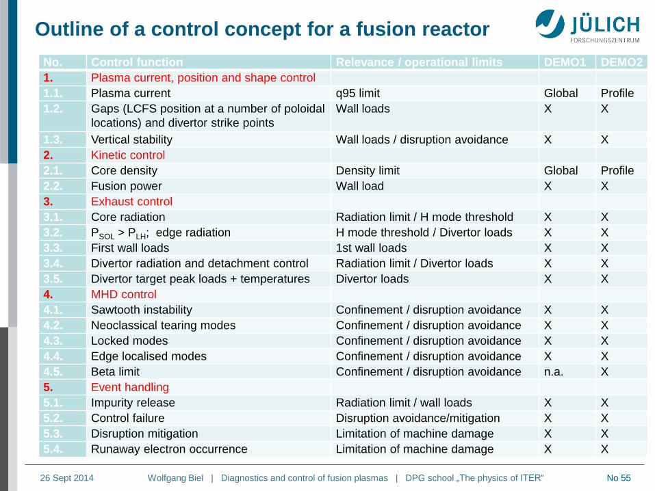
Outline of a control concept for a fusion reactor
No. Control function Relevance / operational limits DEMO1 DEMO2
1. Plasma current, position and shape control
1.1. Plasma current q95 limit Global Profile
1.2. Gaps (LCFS position at a number of poloidal
locations) and divertor strike points
Wall loads X X
1.3. Vertical stability Wall loads / disruption avoidance X X
2. Kinetic control
2.1. Core density Density limit Global Profile
2.2. Fusion power Wall load X X
3. Exhaust control
3.1. Core radiation Radiation limit / H mode threshold X X
3.2. PSOL > PLH; edge radiation H mode threshold / Divertor loads X X
3.3. First wall loads 1st wall loads X X
3.4. Divertor radiation and detachment control Radiation limit / Divertor loads X X
3.5. Divertor target peak loads + temperatures Divertor loads X X
4. MHD control
4.1. Sawtooth instability Confinement / disruption avoidance X X
4.2. Neoclassical tearing modes Confinement / disruption avoidance X X
4.3. Locked modes Confinement / disruption avoidance X X
4.4. Edge localised modes Confinement / disruption avoidance X X
4.5. Beta limit Confinement / disruption avoidance n.a. X
5. Event handling
5.1. Impurity release Radiation limit / wall loads X X
5.2. Control failure Disruption avoidance/mitigation X X
5.3. Disruption mitigation Limitation of machine damage X X
5.4. Runaway electron occurrence Limitation of machine damage X X
Page 56
Wolfgang Biel | Diagnostics and control of fusion plasmas | DPG school „The physics of ITER“ 26 Sept 2014 No 56
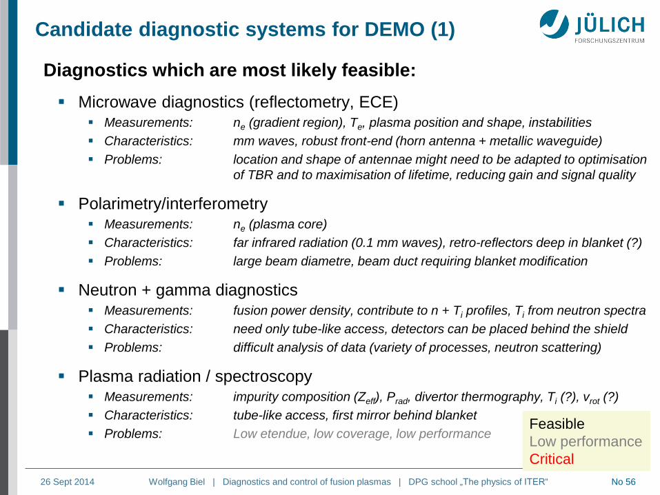
Diagnostics which are most likely feasible:
Microwave diagnostics (reflectometry, ECE) Measurements: ne (gradient region), Te, plasma position and shape, instabilities
Characteristics: mm waves, robust front-end (horn antenna + metallic waveguide)
Problems: location and shape of antennae might need to be adapted to optimisation
of TBR and to maximisation of lifetime, reducing gain and signal quality
Polarimetry/interferometry Measurements: ne (plasma core)
Characteristics: far infrared radiation (0.1 mm waves), retro-reflectors deep in blanket (?)
Problems: large beam diametre, beam duct requiring blanket modification
Neutron + gamma diagnostics Measurements: fusion power density, contribute to n + Ti profiles, Ti from neutron spectra
Characteristics: need only tube-like access, detectors can be placed behind the shield
Problems: difficult analysis of data (variety of processes, neutron scattering)
Plasma radiation / spectroscopy Measurements: impurity composition (Zeff), Prad, divertor thermography, Ti (?), vrot (?)
Characteristics: tube-like access, first mirror behind blanket
Problems: Low etendue, low coverage, low performance
Candidate diagnostic systems for DEMO (1)
Feasible
Low performance
Critical
Page 57
Wolfgang Biel | Diagnostics and control of fusion plasmas | DPG school „The physics of ITER“ 26 Sept 2014 No 57
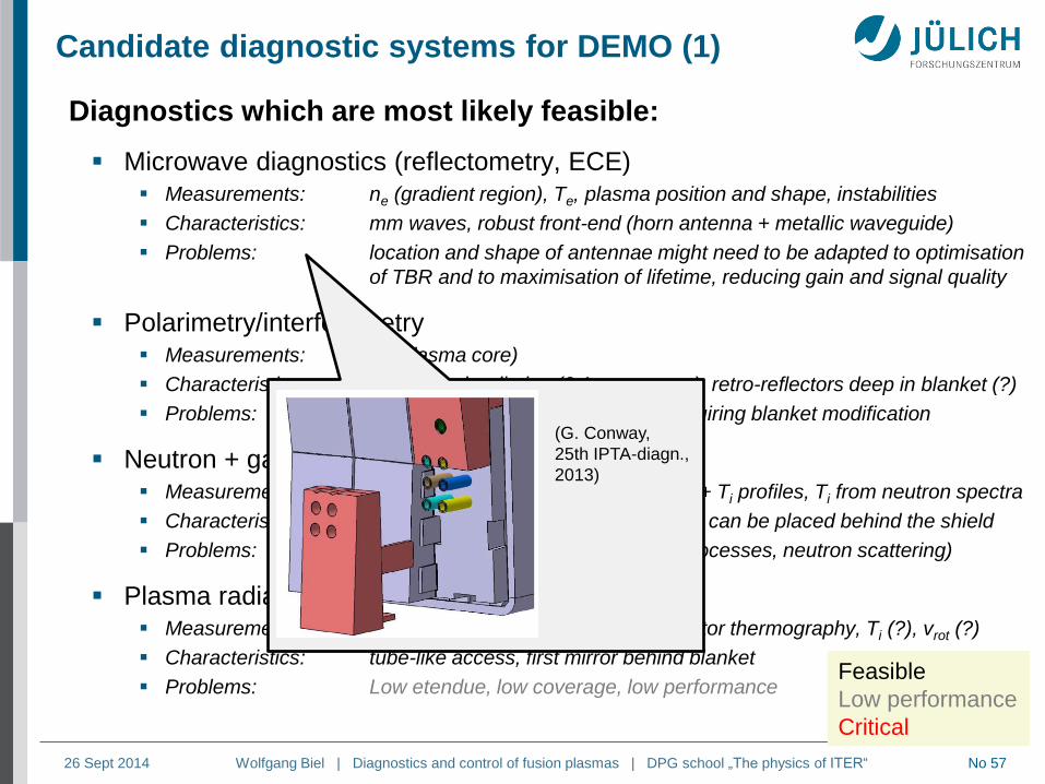
Diagnostics which are most likely feasible:
Microwave diagnostics (reflectometry, ECE) Measurements: ne (gradient region), Te, plasma position and shape, instabilities
Characteristics: mm waves, robust front-end (horn antenna + metallic waveguide)
Problems: location and shape of antennae might need to be adapted to optimisation
of TBR and to maximisation of lifetime, reducing gain and signal quality
Polarimetry/interferometry Measurements: ne (plasma core)
Characteristics: far infrared radiation (0.1 mm waves), retro-reflectors deep in blanket (?)
Problems: large beam diametre, beam duct requiring blanket modification
Neutron + gamma diagnostics Measurements: fusion power density, contribute to n + Ti profiles, Ti from neutron spectra
Characteristics: need only tube-like access, detectors can be placed behind the shield
Problems: difficult analysis of data (variety of processes, neutron scattering)
Plasma radiation / spectroscopy Measurements: impurity composition (Zeff), Prad, divertor thermography, Ti (?), vrot (?)
Characteristics: tube-like access, first mirror behind blanket
Problems: Low etendue, low coverage, low performance
Candidate diagnostic systems for DEMO (1)
Feasible
Low performance
Critical
(G. Conway,
25th IPTA-diagn.,
2013)
Page 58
Wolfgang Biel | Diagnostics and control of fusion plasmas | DPG school „The physics of ITER“ 26 Sept 2014 No 58
Diagnostics which are most likely feasible:
Microwave diagnostics (reflectometry, ECE) Measurements: ne (gradient region), Te, plasma position and shape, instabilities
Characteristics: mm waves, robust front-end (horn antenna + metallic waveguide)
Problems: location and shape of antennae might need to be adapted to optimisation
of TBR and to maximisation of lifetime, reducing gain and signal quality
Polarimetry/interferometry Measurements: ne (plasma core)
Characteristics: far infrared radiation (0.1 mm waves), retro-reflectors deep in blanket (?)
Problems: large beam diametre, beam duct requiring blanket modification
Neutron + gamma diagnostics Measurements: fusion power density, contribute to n + Ti profiles, Ti from neutron spectra
Characteristics: need only tube-like access, detectors can be placed behind the shield
Problems: difficult analysis of data (variety of processes, neutron scattering)
Plasma radiation / spectroscopy Measurements: impurity composition (Zeff), Prad, divertor thermography, Ti (?), vrot (?)
Characteristics: tube-like access, first mirror behind blanket
Problems: Low etendue, low coverage, low performance
Candidate diagnostic systems for DEMO (1)
Feasible
Low performance
Critical
from:
G. Conway,
25th IPTA-diagn.
(2013) (M. A.Van Zeeland, Rev. Sci Instrum, 2013)
Page 59
Wolfgang Biel | Diagnostics and control of fusion plasmas | DPG school „The physics of ITER“ 26 Sept 2014 No 59
Diagnostics which are most likely feasible:
Microwave diagnostics (reflectometry, ECE) Measurements: ne (gradient region), Te, plasma position and shape, instabilities
Characteristics: mm waves, robust front-end (horn antenna + metallic waveguide)
Problems: location and shape of antennae might need to be adapted to optimisation
of TBR and to maximisation of lifetime, reducing gain and signal quality
Polarimetry/interferometry Measurements: ne (plasma core)
Characteristics: far infrared radiation (0.1 mm waves), retro-reflectors deep in blanket (?)
Problems: large beam diametre, beam duct requiring blanket modification
Neutron + gamma diagnostics Measurements: fusion power density, contribute to n + Ti profiles, Ti from neutron spectra
Characteristics: need only tube-like access, detectors can be placed behind the shield
Problems: difficult analysis of data (variety of processes, neutron scattering)
Plasma radiation / spectroscopy Measurements: impurity composition (Zeff), Prad, divertor thermography, Ti (?), vrot (?)
Characteristics: tube-like access, first mirror behind blanket
Problems: Low etendue, low coverage, low performance
Candidate diagnostic systems for DEMO (1)
Feasible
Low performance
Critical
(JET neutron camera)
Page 60
Wolfgang Biel | Diagnostics and control of fusion plasmas | DPG school „The physics of ITER“ 26 Sept 2014 No 60
Diagnostics which are most likely feasible:
Microwave diagnostics (reflectometry, ECE) Measurements: ne (gradient region), Te, plasma position and shape, instabilities
Characteristics: mm waves, robust front-end (horn antenna + metallic waveguide)
Problems: location and shape of antennae might need to be adapted to optimisation
of TBR and to maximisation of lifetime, reducing gain and signal quality
Polarimetry/interferometry Measurements: ne (plasma core)
Characteristics: far infrared radiation (0.1 mm waves), retro-reflectors deep in blanket (?)
Problems: large beam diametre, beam duct requiring blanket modification
Neutron + gamma diagnostics Measurements: fusion power density, contribute to n + Ti profiles, Ti from neutron spectra
Characteristics: need only tube-like access, detectors can be placed behind the shield
Problems: difficult analysis of data (variety of processes, neutron scattering)
Plasma radiation / spectroscopy Measurements: impurity composition (Zeff), Prad, divertor thermography, Ti (?), vrot (?)
Characteristics: tube-like access, first mirror behind blanket
Problems: Low etendue, low coverage, low performance
Candidate diagnostic systems for DEMO (1)
Feasible
Low performance
Critical
first mirror
behind blanket,
L/D > 20…30
Page 61
Wolfgang Biel | Diagnostics and control of fusion plasmas | DPG school „The physics of ITER“ 26 Sept 2014 No 61
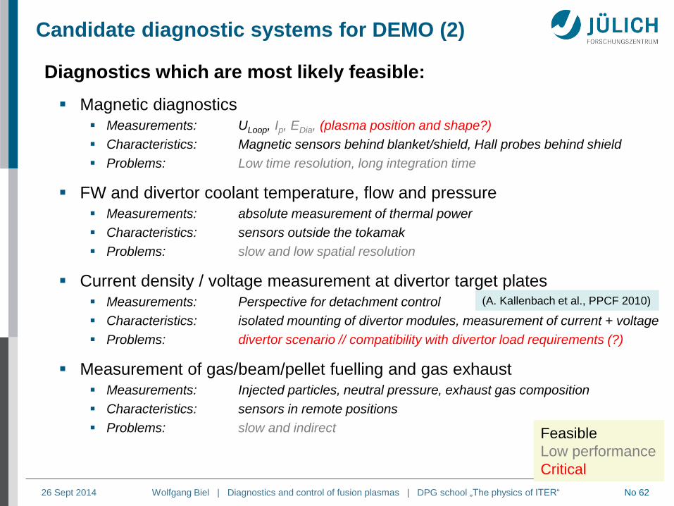
Candidate diagnostic systems for DEMO (2)
Diagnostics which are most likely feasible:
Magnetic diagnostics Measurements: ULoop, Ip, EDia, (plasma position and shape?)
Characteristics: Magnetic sensors behind blanket/shield, Hall probes behind shield
Problems: Low time resolution, long integration time
FW and divertor coolant temperature, flow and pressure Measurements: absolute measurement of thermal power
Characteristics: sensors outside the tokamak
Problems: slow and low spatial resolution
Current density / voltage measurement at divertor target plates Measurements: Perspective for detachment control
Characteristics: isolated mounting of divertor modules, measurement of current + voltage
Problems: divertor scenario // compatibility with divertor load requirements (?)
Measurement of gas/beam/pellet fuelling and gas exhaust Measurements: Injected particles, neutral pressure, exhaust gas composition
Characteristics: sensors in remote positions
Problems: slow and indirect Feasible
Low performance
Critical
(typical pick-up coil) (metallic Hall sensor
prototype, I. Duran et al.)
(A. Kallenbach et al., PPCF 2010)
Page 62
Wolfgang Biel | Diagnostics and control of fusion plasmas | DPG school „The physics of ITER“ 26 Sept 2014 No 62
Candidate diagnostic systems for DEMO (2)
Diagnostics which are most likely feasible:
Magnetic diagnostics Measurements: ULoop, Ip, EDia, (plasma position and shape?)
Characteristics: Magnetic sensors behind blanket/shield, Hall probes behind shield
Problems: Low time resolution, long integration time
FW and divertor coolant temperature, flow and pressure Measurements: absolute measurement of thermal power
Characteristics: sensors outside the tokamak
Problems: slow and low spatial resolution
Current density / voltage measurement at divertor target plates Measurements: Perspective for detachment control
Characteristics: isolated mounting of divertor modules, measurement of current + voltage
Problems: divertor scenario // compatibility with divertor load requirements (?)
Measurement of gas/beam/pellet fuelling and gas exhaust Measurements: Injected particles, neutral pressure, exhaust gas composition
Characteristics: sensors in remote positions
Problems: slow and indirect Feasible
Low performance
Critical
(A. Kallenbach et al., PPCF 2010)
Page 63
Wolfgang Biel | Diagnostics and control of fusion plasmas | DPG school „The physics of ITER“ 26 Sept 2014 No 63
Integrated plasma diagnostics processing & control
actuator commands Tokamak
state
measurements
[Real-time control]
Plasma
controller
Plasma state
reconstruction
abnormal meas.
Fault
detection
state
Controller Observer
Supervision
Plasma controller: perform control actions based on full plasma state knowledge
Plasma state reconstruction: derive plasma state by merging measurements
from several diagnostics
Fault detection: classify unexpected measurements (e.g. off-normal events,
faulty signals)
Diagnostic redundancy in number of channels and number of methods facilitates
handling of faults (the better the model, the less measurements are needed)
(F. Felici, M. de Baar)
Page 64
Wolfgang Biel | Diagnostics and control of fusion plasmas | DPG school „The physics of ITER“ 26 Sept 2014 No 64
actuator commands
Tokamak state
measurements
[Real-time control]
Plasma
controller
next time
Tokamak
Simulation
predicted state
predicted measurements -
measurement residual
Fault
detection &
classification
state
+
updated state
state
update
Observer
gain
Exception
handling
Controller Model-based, dynamic state estimator ("observer") Supervision
Dynamic observer for tokamak plasma state
Run tokamak simulation in parallel with plasma evolution
Correct simulated state estimate based on difference between predicted and true
measurements
Detection & classification of excessive discrepancies
The plasma controller may initiate fast rampdown or disruption mitigation if a
discrepancy cannot be resolved otherwise
(F. Felici, M. de Baar)


![ASIC/TRB Readout Status in Jülich - Indico [Home] · z-t ASIC/TRB Readout Status in Jülich Peter Wintz (IKP, FZ Jülich) STT RO WShop, Krakow, Jan-30/31 2016](https://static.documents.pub/doc/80x56/5e0a051f15f04325a03fce44/asictrb-readout-status-in-jlich-indico-home-z-t-asictrb-readout-status-in.jpg)


