This paper is included in the Proceedings of the 13th USENIX Symposium on Networked Systems Design and Implementation (NSDI ’16). March 16–18, 2016 • Santa Clara, CA, USA ISBN 978-1-931971-29-4 Open access to the Proceedings of the 13th USENIX Symposium on Networked Systems Design and Implementation (NSDI ’16) is sponsored by USENIX. Diamond: Nesting the Data Center Network with Wireless Rings in 3D Space Yong Cui and Shihan Xiao, Tsinghua University; Xin Wang, Stony Brook University; Zhenjie Yang and Chao Zhu, Tsinghua University; Xiangyang Li, Tsinghua University and University of Science and Technology of China; Liu Yang, Beijing University of Posts and Telecommunications; Ning Ge, Tsinghua University https://www.usenix.org/conference/nsdi16/technical-sessions/presentation/cui
Transcript
This paper is included in the Proceedings of the 13th USENIX Symposium on Networked Systems
Design and Implementation (NSDI ’16).March 16–18, 2016 • Santa Clara, CA, USA
ISBN 978-1-931971-29-4
Open access to the Proceedings of the 13th USENIX Symposium on
Networked Systems Design and Implementation (NSDI ’16)
is sponsored by USENIX.
Diamond: Nesting the Data Center Network with Wireless Rings in 3D Space
Yong Cui and Shihan Xiao, Tsinghua University; Xin Wang, Stony Brook University; Zhenjie Yang and Chao Zhu, Tsinghua University; Xiangyang Li, Tsinghua University and
University of Science and Technology of China; Liu Yang, Beijing University of Posts and Telecommunications; Ning Ge, Tsinghua University
USENIX Association 13th USENIX Symposium on Networked Systems Design and Implementation (NSDI ’16) 657
Diamond: Nesting the Data Center Network withWireless Rings in 3D Space
Yong Cui1, Shihan Xiao1, Xin Wang2, Zhenjie Yang1, Chao Zhu1, Xiangyang Li1,3, Liu Yang4,and Ning Ge1
1Tsinghua University2Stony Brook University
3University of Science and Technology of China4Beijing University of Posts and Telecommunications
Abstract
The introduction of wireless transmissions into the da-ta center has been shown to be promising in improvingthe performance of data center networks (DCN) cost ef-fectively. For high transmission flexibility and perfor-mance, a fundamental challenge is to increase the wire-less availability and enable fully hybrid and seamlesstransmissions over both wired and wireless DCN com-ponents. Rather than limiting the number of wireless ra-dios by the size of top-of-rack (ToR) switches, we pro-pose a novel DCN architecture, Diamond, which neststhe wired DCN with radios equipped on all servers. Toharvest the gain allowed by the rich reconfigurable wire-less resources, we propose the low-cost deployment ofscalable 3D Ring Reflection Spaces (RRSs) which are in-terconnected with streamlined wired herringbone to en-able large number of concurrent wireless transmissionsthrough high-performance multi-reflection of radio sig-nals over metal. To increase the number of concurrentwireless transmissions within each RRS, we propose aprecise reflection method to reduce the wireless interfer-ence. We build a 60GHz-based testbed to demonstratethe function and transmission ability of our proposed ar-chitecture. We further perform extensive simulations toshow the significant performance gain of Diamond, insupporting up to five times higher server-to-server capac-ity, enabling network-wide load balancing, and ensuringhigh fault tolerance.
1 IntroductionThe high-performance data center network (DCN) isan essential infrastructure for cloud computing. Thereis a quick growth of large-scale services (e.g., GoogleSearch, Hadoop, MapReduce, etc.) in the cloud, andrecent measurements show tremendous traffic variationsover space and time in DCNs [5, 7, 8, 20]. Convention-al wired DCNs generally adopt the fixed and symmetricnetwork design. This may lead to prevalent hot spots
across different layers of the architecture which signifi-cantly reduces the performance of DCNs [7, 20, 37].
There are some recent interests on constructing hybridDCNs [18, 19, 33, 38, 39] with the introduction of newnetwork components such as optical circuit switches orwireless radios into the DCNs to provide configurablelinks [9,13,25,28]. Although these hybrid infrastructuresshow the potential in achieving higher DCN capacity andlower transmission delay, their wired structures are keptunchanged even though they are not primitively designedto work with new network techniques, which limits theperformance of hybrid DCN. Specifically, the new net-work components are added directly into conventionalDCNs or are applied to replace part of existing networkswitches [18, 33, 38, 39]. Considering only the local per-formance improvement, it is hard for existing schemes toachieve the global optimal performance in the presenceof network-wide traffic changes. The key challenge of afully hybrid network design is to form a novel hybrid net-work architecture that can take full advantage of differen-t network techniques and enable coherent and seamlesstransmissions for much higher DCN performance.
The low cost of today’s commodity 60GHz radiosmakes their wide deployment a better option in a ful-ly hybrid network design [39]. Providing high wirelessavailability in the data center is the key to achieving highperformance gain in a hybrid architecture. In existingproposals for hybrid DCNs, wireless radios are generallydeployed on a flat 2D plane at the top of racks, whichis susceptible to signal blocking [38]. Although a flatreflector on the room ceiling was proposed to alleviatethe problem [19,38], the ceiling height is quite restricted(3 meters [38]) and the method requires clearance aboveracks, which is usually infeasible in conventional datacenters. The small rack size also restricts the number ofradios that can be placed on each rack (at most eight ra-dios per rack [38, 39]). If radios are densely deployedon top of racks, the strong inter-ratio interference wouldrestrict the number of concurrent wireless links thus con-
658 13th USENIX Symposium on Networked Systems Design and Implementation (NSDI ’16) USENIX Association
straining the system performance [39]. The need of de-ploying more radios and links in the hybrid network forhigher wireless availability calls for a completely newDCN architecture design.
In this work, we propose a novel fully-hybrid networkarchitecture, named Diamond, which ensures high wire-less availability for efficient and high-performance DCNcommunications. Rather than restricting the radios tobe on top of racks, we propose to deploy wireless ra-dios along with a large number of servers. To avoidthe interference among dense radios at the 2D plane,we propose to construct multiple Ring Reflection Spaces(RRSs) to make the radios sparsely distributed in the3D space. Inside each RRS, we develop a novel multi-reflection method to address the blocking problem onbuilding wireless links. With our design, there is no needof changing the room plan above racks. Diamond hasthree key design features:
Novel hybrid network topology (§2): Rather thanadding wireless radios directly on top of racks, we pro-pose a fully hybrid network topology by constructingRRSs in Diamond to facilitate wireless transmissions andisolate the wireless interference. It also supports direc-t server-to-server wireless links rather than conventionalrack-to-rack links. Then we apply a streamlined wiredherringbone to interconnect the RRSs at low cost.
Precise multi-reflection of wireless links (§3): Thesusceptibility to blocking and the interference are twomajor issues that limit the wireless performance in DCN-s. To the best of our knowledge, this is the first work thatdevelops the multi-reflection transmission method to ad-dress the challenge of signal blocking. We further designa novel precise reflection scheme to efficiently restrict thewireless interference in the presence of a large number ofconcurrent wireless links.
Wireless & wired hybrid routing (§4): We proposean opportunistic hybrid routing scheme to allow for lowtransmissions delay and graceful fault tolerance. We fur-ther show that the network diameter of Diamond can s-cale logarithmically with the server number to effectivelybound the route length.
We implement a 60GHz-based testbed, and our exper-imental results confirm the high performance of multi-reflection, and demonstrate that proper reflection holescan efficiently reduce the interference in 3D space (§6).Driven by the testbed parameters, our simulations showthat Diamond can support up to five times higher server-to-server capacity and ensure graceful fault tolerance(§7). Finally, we introduce the related work (§8) anddraw the conclusions (§9).
2 ArchitectureIn this section, we first introduce the basic architectureand methodologies used in the Diamond system, and
then present its hybrid topology design.
2.1 Diamond system overview
At a high level, the Diamond system should meet the datacenter needs at different timescales. First, the configura-tion of wireless links should be updated periodically sothat the network topology can better accommodate thecurrent traffic of the data center. Second, given a con-figured network, we need to efficiently route the flows inreal time.
Dynamic wireless configuration: Following the pri-or studies, the Diamond system exploits the controllerof software-defined networking (SDN) for flexible andefficient configuration of the wireless links and routingpaths [4,11,26,27]. More specifically, the Diamond con-troller periodically updates the configuration of the wire-less links based on the traffic conditions reported fromSDN-controllable ToR switches. Servers are equippedwith high-capacity wireless radios (60GHz radio [18] orFSO transceivers [19]). To dynamically configure thewireless links, they are allowed to communicate witheach other either directly by steering and aligning theantennas (physically or electronically driven [18, 19]) orusing a multi-reflection method we propose. The con-troller first builds wireless links to alleviate the heavytraffic from the hot spots, and then randomly forms addi-tional wireless links using the remaining available radiosto achieve the benefits of random networking [31].
Hybrid routing: The controller only computes therouting paths of hot-spot server pairs during the wire-less configuration to alleviate the hot-spot traffic globallyfor the network-wide load balancing thus higher networkthroughput. For other light-loaded server pairs, the rout-ing decision is made distributedly by servers and switch-es so that their traffic can go through available wirelesslinks opportunistically to cut short the routing paths inreal time.
2.2 Key methodologies
There are two main challenges to implement a fully hy-brid network: (1) When a large number of wireless linksare enabled, the interference will restrict the number ofconcurrent transmissions; and (2) When a large numberof wireless radios are deployed, the high-frequency wire-less links are easily blocked by obstacles such as the sup-ply pipes of air conditioning or the steel structures aboveracks. In light of these problems, Diamond applies a 3Ddeployment of the wireless radios to facilitate high num-ber of concurrent wireless transmissions taking advan-tage of the following key techniques:
Space division multiplexing: To disperse the wirelessradios, the radios in Diamond are installed with serversat different heights. Rather than deploying the wireless
USENIX Association 13th USENIX Symposium on Networked Systems Design and Implementation (NSDI ’16) 659
radios densely on only one flat 2D plane, we place thewireless radios on several separated large annular sur-faces. Thus the deployment density of wireless radios ismuch lower than that of previous studies [38, 39]. Theadjacent annular surfaces form a RRS where the signalcan run from one radio to another. Due to the space di-vision, the same set of wireless channels can be multi-plexed across different RRSs, which helps isolate the in-terference in Diamond.
Multi-reflection transmission: Although more radioscan be deployed in a 3D space, many radios cannot reacheach other with existing direct point-to-point transmis-sion or the one-reflection transmission [18, 19, 38, 39]due to the obstacle blocking. Instead, in Diamond, weutilize multiple reflections to bounce the signal emittedfrom one server to another. This helps to greatly increasethe number of available wireless links. Following the pri-or work [38], our testbed experiment confirms that usingthe flat metal board as reflector can offer very good spec-ular reflection with little energy loss or changing pathloss during each reflection. This avoids the overhead ofbuffering and switching packets in multiple hops over in-termediate switches.
Different types of directional antennas may have d-ifferent beam widths [18]. For a multi-reflection path,there is a tradeoff between the antenna beam width andthe tolerance for the antenna alignment error. The nar-rower the beam width, the higher the antenna gains,but the less the alignment error tolerance. In the ex-treme case of using FSO with nearly zero beam width,previous study shows that using electrically-driven Gal-vo mirrors is possible to implement precise steeringcontrol [19]. For conventional 60GHz antennas, theelectrically-driven antenna array is promising to satisfythis requirement [18, 39].
Precise reflection technology: Since the wireless an-tenna may have a wide beam width [18], multiple re-flections would introduce unexpected interference insidethe 3D space due to the signal leakage of the beam(e.g., the undesired side lobes of the 60GHz wirelessbeam [18, 29]). In order to efficiently restrict and con-trol the interference caused by reflections, we develop aprecise reflection method with the careful placement ofabsorbing materials on the reflection boards. Most areasof the board are covered by absorbing paper while smallholes are left so that only the intended signal reflectionsare made by hitting the hole, which leads to very littlesignal leakage.
2.3 Topology designThe basic motivation of the Diamond topology design isto enable more concurrent wireless transmissions. In ourdesign, we separate the specific transmission functionsof wireless and wired links in the network, so that both
Reflector Wireless Link Source Server(a) Top View (b) Side View
Dest Server
A
B
A
B
RRS
A
Reflection Point
Layer
Reflection Point
RRS Width
Figure 1: Brief view of the wireless ring in Diamond(N=4 rings and H=4 layers)
their distinct advantages on the transmission can be ful-ly explored. We construct a ring-shape basic structurethat enables wireless-only transmissions inside the ringemploying the multi-reflections (§2.2). Then we applythe stable wired links to address the transmissions acrossdifferent ring structures.
From the top view in Fig. 1, Diamond’s topology isconstructed by several concentric regular polygons withincreasing radius. Polygons are numbered from insideto outside and named by rings, i.e., {Ri}, 1 ≤ i ≤ N,where N is the total number of polygons. The ith ringhas 4i edges. The racks are placed at the vertex points ofeach ring, and there are totally 1≤i≤N (4i) = 2(N2+N)racks, while flat metal reflectors are put at the edge ofeach ring. Rather than mounting the reflectors [19,38] onthe ceiling, reflectors in Diamond stand in perpendicularto the ground and have the same height as that of racks,which avoids the need of using clear ceiling space forwireless transmissions in data centers. In the following,we introduce the designs of major Diamond components.
Server and rack. Each rack holds multiple serversat different height. The servers inside different racks atthe same height form a layer, and the layers are num-bered from the top to the bottom as {l j}, 1 ≤ j ≤ H. Theheight of each layer equals the height of a server at con-ventional racks, and the number of layers H equals to thenumber of servers in one rack. Therefore, a Diamondtopology can accommodate totally 2(N2 +N)H server-s. Each server is equipped with 1 Ethernet port and 2wireless ports with directional antennas. The network-ing principles in Diamond are: (1) the links between twoservers are wireless; (2) the links between a server andits ToR switch or between two ToR switches are wired.
Wireless links: The 3D space between two neighbor-ing rings is called an RRS. For each server, one of itsantennas points to RRS at its inner side and the otherpoints to RRS at its outer side. By adjusting the antennadirections in the RRS, each server at ring Ri can flexi-bly communicate with other servers at different heightson rings Ri, Ri−1 and Ri+1 through direct transmissionsor multiple reflections on different reflectors (Fig. 1 andFig. 3).
660 13th USENIX Symposium on Networked Systems Design and Implementation (NSDI ’16) USENIX Association
Virtual SwitchRow
ToR Switch
Reflector
Column
(a) Logical view (b) Physical view
ToR SwitchVirtual Link (Row) Virtual Link (Column)
Reflector
Figure 2: Top view of the wired herringbone of Diamond(N=3 rings)
Wired links: With wireless links formed locallyinside each RRS, the wired links are applied to intercon-nect different RRSs. Fig. 2 gives a top view of the wiredconnections in Diamond. Similar to conventional DCN-s, the servers on each rack are connected to the commonToR switch. Fig. 2(a) shows the logical view of the wiredherringbone. We number the horizontal lines in Fig. 2(a)from the top to the bottom as rows {ri}, 1 ≤ i ≤ 2N,and number the vertical lines from the left to the rightas columns {ci}, 1 ≤ i ≤ 2N. Fig. 2(b) shows the phys-ical connections of the wired herringbone. The princi-ple of Diamond to interconnect the RRSs is that the ToRswitches on the same row (or column) are interconnectedby a virtual switch, while the ToR switches on differentrows and different columns are not directly connected.
To implement the function of virtual switch, we havethe option of applying any existing structure, e.g., thetree-based structure (Fat-tree [3]) or cube-based structure(BCube [16]), to interconnect the ToR switches on eachrow and each column. These structures may make thewired design of Diamond complex and costly. In Di-amond, we prefer to apply the de-Bruijn graph [12] sothat no additional switches are required. De-bruijn is at-tractive for providing constant link degree at each nodeand logarithmic network diameter. Then the path lengthis bounded and the routing structure is still simple (§4).Although using de-Bruijn structure often involves com-plex wiring [17], the wiring is kept simple in Diamondbecause only one row (or column) of ToR switches areconnected as one de-Bruijn.
2.4 Rack and reflector arrangementThere are two requirements to arrange the racks in Dia-mond to facilitate its practical and scalable deployment:first, all the reflector boards should be flat and have thesame length to facilitate their economical production;second, the RRS width should be kept stable, with theRRS width close to a fixed value when the number ofrings increases. We call the physical distance betweentwo neighboring rings Ri and Ri+1 as the RRS width Δi(Fig. 1). Too large a RRS width will make Diamond oc-
C
Reflection Path Wireless/Wired Hybrid Path
Wired LinkWireless Link Source Server Dest Server
Reflection Points
Figure 3: Routing in the 3D wireless ring
cupy too much room area, while too small a RRS widthwill not leave enough space for wireless transmissions.
As mentioned earlier, all the polygons in Diamond areregular with the same edge length and are put concen-trically in a symmetric way as shown in Fig. 2. The re-flector height equals the height of racks, and the reflectorlength is denoted as L. Then our design ensures the RRSwidth Δi at ith ring to have the following property:
Property 1. limi→∞
Δi = 2L/π
Proof. Based on the topology of Diamond, the radiusdi of ring Ri is di = (cot π
4i )L2 . Then we have Δi =
di+1−di = (cot π4(i+1) −cot π
4i )L2 =
sin( π4
1i(i+1) )
sin[( π4 )
2 1i(i+1) ]
L2 . Hence
we have limi→∞
Δi = 2L/π .
Based on the above proof, the RRS width Δi decreas-es as the ring number i becomes larger. Property 1 en-sures that the RRS width does not fall to zero but reach-es a fixed limit value. For a setting L=2.5m, the RRSwidth Δi can keep a value close to the fixed limit value1.6m. We can see that the RRS width becomes stable andapproaches the fixed limit value quickly when the ringnumber increases, which demonstrates the scalability ofthe Diamond design.
3 Wireless configuration
In this section, we first introduce our schemes of find-ing the reflection path when building a wireless link andeliminating the wireless interference during the reflec-tions, and then present our strategies in forming flexiblewireless configurations for network-wide load balancing.
3.1 Reflection pathSince the physical topology of Diamond is fixed, the re-flection paths can be easily calculated between any twoservers. The calculation of the reflection path table isdone offline at the initial deployment of Diamond. Ifthere are multiple paths available between two servers,we choose the one with the least number of reflection
USENIX Association 13th USENIX Symposium on Networked Systems Design and Implementation (NSDI ’16) 661
Figure 4: Number of reach-able racks per server at dif-ferent rings and within dif-ferent reflection times
5 10 15 20 25 30 35 40 45 500
0.1
0.2
0.3
0.4
0.5
0.6
0.7
0.8
Index of ring
Reu
se ra
tio
Figure 5: Reuse ratio of re-flection points on a board atdifferent rings
times (direct transmission is considered as zero times ofreflection). Given a source server and a destination serv-er in Diamond, if a reflection path can be found in thetable, the antenna angles can be adjusted by the serversaccording to the table values to build the wireless link.
Based on the Diamond topology, we simulate the re-flection paths between all the server pairs. Fig. 4 showsthe average communication range of a wireless radio,i.e., the reachable rack number at both its current ring Riand inner ring Ri−1. We can see that no more than threereflections can cover above 90% racks in the RRS whenthe ring number is less than 9. For a ring number largerthan 4, a server can reach at least 10 racks through the di-rect transmission, 20 racks within a single reflection and28 racks within two reflections.
3.2 Reduction of wireless interferenceWe design a precise reflection method to alleviate thewireless interference during reflections. Specifically, wecarefully place the absorbing materials on the reflectionboard and leave small holes for only the intended reflec-tion points. In the following, we analyze the density anddistribution of reflection points (i.e., the reflection holes)on the reflector boards.
To simplify the analysis, we first present a special cir-cle case where the flat reflectors are replaced by curvedreflectors so that all the polygons are transformed totheir circumcircles. We consider the communication ofservers inside the kth RRS, i.e., the communication be-tween a server on ring k and another on ring k+1 and thecommunication between two servers on ring k+ 1. Thereflection times are limited within three. The commu-nication of servers in different rings is achieved by zeroand double reflections. The double reflection forms thereflection points on the outer side of ring k and the innerside of ring k+1.
Considering the distribution of reflection points onring k, we have the following property:
Property 2. At each layer of Diamond, for an arbitraryreflector on ring k, there are at most six reflection pointson the reflector board.
Proof. Based on the coordinates of a server n on ringk+1 and a server m on ring k, we obtain the central an-gle for each reflection point, denoted as 2
3 · π(2n−1)4(k+1) + 1
3 ·π(2m−1)
4k , m,n ∈ Z+. We shift the value of m and n to findthe minimum change of the central angle of the reflectionpoint. The minimum change π
12k is the minimum inter-val of two reflection points. As the central angle for thereflector on ring k is π
2k , there are at most six reflectionpoints at each layer of the reflector board. This com-pletes the proof.
We obtain the expressions of the central angle for eachreflection point in ring k+ 1 following the same proce-dure of ring k. We examine the distribution of reflectionpoints on each reflector in ring k+1 based on simulationresults, and found that at each layer from the ring 5 tothe ring 50, there are average ten reflection points on theboard of the ring k+1. One hole may be reused by a largenumber of reflection points for different reflection paths,i.e., the distance between two reflection points is smallenough to overlap with each other. With the reuse ratioequal to the ratio of reused points to the total number ofreflection points, Fig. 5 shows that the reuse ratio is highand increases when the ring number becomes larger.
3.3 Configuration for hot-spot trafficSince the above techniques enable a large number ofserver-to-server wireless links, Diamond can implemen-t a network-wide reconfigurable topology for balancingthe identified hot-spot traffic, which contributes to highthroughput and effective routing.
Configuration problem: The wireless configurationis determined by the network controller in DCNs. Thecontroller input is a traffic demand matrix where an en-try describes the traffic demand between a pair of servers.Given a hybrid topology G, we can construct its interfer-ence graph GI
1 to describe the conflict relations amongall the wireless links based on offline measurements [18].The objective of our wireless configuration is to selectthe optimal independent set (IS) 2 to minimize the max-imum link utilization of the entire network during eachscheduling period. We thus have an integer linear pro-gramming (ILP) problem HLBP (Hybrid Load BalanceProblem). Our HLBP problem mainly differs from pre-vious study Firefly [19] on the additional wireless inter-ference constraint on IS selections. Finding all the ISsis NP-complete in general [14]. We find that even thestate-of-art ILP solver LINGO or ILP toolbox in MAT-LAB may take above tens of minutes to solve the HLBP.
1The independent graph GI of G is defined as a graph where eachlink in G corresponds to a vertex in GI , and if two links have conflictin G, then there is a link between them in GI .
2An independent set (IS) in an interference graph GI is defined as avertex subset where any two vertices do not conflict.
662 13th USENIX Symposium on Networked Systems Design and Implementation (NSDI ’16) USENIX Association
DH DW BC 3DB FT0
0.2
0.4
0.6
0.8
1P
ath
Leng
th R
atio
6
5
4
3
2
1
Hops
Figure 6: Path length ratio of different topologies
There are some existing studies [21–23, 34–36] on find-ing an approximate IS solution in some special interfer-ence graphs. In the following, in order to make Diamondsupport various types of antennas, we turn to the develop-ment of a fast heuristic solution for a general interferencegraph.
Greedy scheduling: We design a greedy algorithmHDF (Highest Demand First) to provide a faster and sim-pler solution for HLBP. The algorithm assigns a weightvalue to wireless links related to the flows, and then s-elects a set of non-conflict wireless links that maximizethe sum of weights. We define the weight of a wirelesslink as the ratio between the flow demand and the linklength. For a link with reflections, the link length is thetotal geometric length of the reflection path. The intu-ition is that a link can provide larger benefit when servinghigher flow demand over a shorter link length, as a short-er wireless link allows for smaller interference range andhigher SNR thus higher link capacity. We greedily selectthe links with the largest weight to build first and removethe links that conflict with the selected links. Next, thetraffic demands are split into their shortest paths. Denotethe minimum remaining capacity of links along a pathas the path capacity. The server pair with the highestdemand first splits the traffic to transmit over the set ofshortest paths in proportional to the path capacity. Thenthe remaining link capacities are updated and the proce-dure repeats until no server pair is left. The gap betweenHDF and the optimal solution is evaluated in §7.
3.4 Random networking for high capacityand low delay
Since the wireless resources are rich in Diamond, afteroffloading the hot-spot traffic by HDF, some wireless ra-dios may be left unused, particularly when the number ofhot spots in the network is not big in a scheduling peri-od. Random networking is shown to have the features ofsmall average path length, high path diversity and highserver-to-server network capacity [31, 32]. Thus we ex-pect that the random formulation of wireless links helpsto shorten the path length in Diamond.
To verify this effect, we compare the percentage of thepath length for all the server pairs under different DCNtopologies with 512 servers in Fig. 6. DH is for Diamondwhere wireless links are built randomly; DW is for Dia-mond with the wired connections only; BC is the BCube
topology [16]; FT is the Fat-tree topology [3]; 3DB isa Fat-tree topology augmented by 3D-beamforming ra-dios at ToR switches [38]. We can see that the number oflong paths in DW is larger than that in BCube. Howev-er, when introducing random wireless links, the ratio ofshort paths in DH is higher than all the other topologies.The short path length generally implies small hop delayand high end-to-end throughput due to fewer congestionpoints at intermediate routing hops [31, 32].
To benefit from the random networking in Diamond,we extend the IS selected by the HDF algorithm to amaximal IS, named the MIS, by randomly adding addi-tional wireless links into the IS without creating conflic-t until no such kind of wireless link is available. Therandom formulation of wireless links in Diamond avoidsthe problem of complex wiring and costly managementappearing in the previous work on using random wiredlinks in DCNs [32].
4 Routing Design
Diamond is built upon a topology-adaptive network,while existing routing protocols often impose a relative-ly long convergence time when the topology changes [6].For more efficient routing, we propose to use a set of s-trategies in Diamond.
4.1 Overall schemeThe setup of wireless links is performed by the Dia-mond controller periodically. We denote the time in-terval for the controller to execute the wireless recon-figuration as one period. At the beginning of each pe-riod, a set of operations will be performed as follows:(1) The controller computes the wireless configurationand the routing paths for hot-spot server pairs using themethods described in §3, and sends out the instruction-s to both servers and their associated ToR switches. (2)The servers receiving the configuration instructions willadjust their antenna directions accordingly.
To summarize, there are three choices for a server orToR switch to route its traffic. First, a server or ToRswitch tries to match the routing rules designated by thecontroller. If matched, it delivers the packet according-ly. This first choice helps to balance the hot-spot trafficfollowing the controller’s decisions. Otherwise, it oppor-tunistically utilizes its available wireless radios (if it is aserver) or the available radios on its rack (if it is a ToRswitch) to create a short-cut hop to the destination. Thissecond choice contributes to shorter routing path throughopportunistic hybrid routing. If no wireless radios areproper to use, it delivers the packet to the next-hop nodefollowing a default wired routing path. This last choiceefficiently bounds the worst-case performance by routingthrough the wired herringbone.
USENIX Association 13th USENIX Symposium on Networked Systems Design and Implementation (NSDI ’16) 663
4.2 Default wired routingFor the Diamond topology introduced in §2.3, a 3-tuple(x,y,z) labels a server at the xth row, yth column and zthlayer. For simplicity, we use a 3-tuple (x,y,0) to label aToR switch on the xth row and yth column. Fig. 7 showsa simple example to route from an arbitrary source serv-er s1 = (x1,y1,z1) to a destination server s2 = (x2,y2,z2).Let w1 = (x1,y1,0) and w2 = (x2,y2,0) denote theircorresponding ToR switches respectively. The shortestwired routing path can be established as follows. First,the packet routes from s1 to w1 and then we change oneof the two coordinates of source ToR switch w1 at a timeto match that of switch w2: (x1,y1,0) → (x2,y1,0) →(x2,y2,0). Finally, the packet routes from w2 to s2. Notethat each coordinate change corresponds to hops througha virtual switch.
Suppose we apply de-Bruijn structure to implemen-t the virtual switch, and the Diamond topology has total-ly H = 2p layers and N rings. Then we need 4p ports perToR switch, where 2p ports connect to the servers on therack and 2p ports are used for constructing the de-Bruijnon its row and column. Since the diameter of a de-Brujingraph is logp N, the path length through a virtual switch(i.e., the path length between two ToR switches on onerow or column) can be bounded by logp N. Based on theabove routing procedure, we have the property:
Property 3. The network diameter, which is the longestshortest path among all the server pairs, of Diamond isbounded by 2logp N +2.
Since the Diamond with H layers and N rings can sup-port totally n = 2(N2 +N)H servers, we have the diame-ter of Diamond as O(logp n). Compared to conventionalapproaches (e.g., the Fat-tree [3] or VL2 [15] topology)which has a constant diameter but the number of switchports increase with the number of servers, Diamond hasmuch better scalability. As the server number increases,its network diameter extends logarithmically while theport number can be kept as a constant. This is similar tothe recursion-based DCN topology such as BCube [16]and DCell [17]), which also has a logarithmic diameterwhen keeping a constant number of switch ports.
4.3 Opportunistic hybrid routingThe wired herringbone of Diamond provides the basicassurance of the connectivity and route length bound.Now we integrate the wireless transmissions into thedefault wired paths opportunistically. Suppose a serv-er s1 = (x1,y1,z1) receives a packet for a server s2 =(x2,y2,z2), and the ToR switches of s1 and s2 are w1 =(x1,y1,0) and w2 = (x2,y2,0). The server s1 is e-quipped with two radios, which are pointed to serverss�1 = (x3,y3,z3) and s��1 = (x4,y4,z4), respectively. Define
Virtual switch
ToR switch
Server
Source server
Dest server
Virtual link
Wired link
Wireless link
Figure 7: Opportunistic hybrid routing in Diamond
a hamming distance D(s1,s2) as the number of the un-matched coordinates between the tuples s1 and s2. Thenthe value range of D(s1,s2) is {0,1,2,3}.
To perform the opportunistic hybrid routing (OHR),each server in Diamond simply follows two steps for thepacket forwarding: (1) Call d1 = D(s1,s2). If all threeare matched (i.e., d1 = 0), then it is the destination serv-er. (2) Call d�
1 =D(s�1,s2) and d��1 =D(s��1 ,s2). If d�
1 < d1or d��
1 < d1, forward the packet to the server s�1 or s��1 ac-cordingly through a wireless radio. Otherwise, forwardthe packet to the switch w1 by default.
Similar to the servers, each ToR switch in Diamondforwards the packet as follows: (1) Call d1 = D(w1,s2).If the first two are matched (i.e., d1 = 1), it forwards thepacket to s2 directly; Otherwise, it randomly chooses onecoordinate among the unmatched ones. Assume that ToRswitch picks x1 where x1 �= x2, then the default next hopis w f = (x2,y1,0). (2) For each server si in the rack,suppose its wireless radios point to two servers s�i ands��i . Call d�
i = D(s�i,s2) and d��i = D(s��i ,s2). If d�
1 < d1 ord��
1 < d1, forward the packet to the sever si in the rack;Otherwise, forward the packet to the ToR switch w f bydefault.
4.4 Fault-tolerance
The redundancy of available paths between any pairof servers make Diamond attractive for fault-tolerance.There are two types of failures to handle in Diamond:node failure and link failure. Three classes of node fail-ure should be considered: (a) switch failure, (b) serverfailure and (c) wireless radio failure. A link failure willbe resulted from a node failure, or the change of the en-vironment such as the blocking of wireless communica-tions due to the human movement in the RRSs. Clearly,due to the nested structure of Diamond, any single nodeor link failure does not lead to the network disconnec-tion. We describe link failures here because other nodefailures trigger the same responses.
In Diamond, each server has three different outputlinks to forward the packets: (a) forward to the ToRswitch it connects to; (b) forward to one of its two wire-less radios. When a server finds one of its output linksfails, it removes that wired/wireless connection from its
664 13th USENIX Symposium on Networked Systems Design and Implementation (NSDI ’16) USENIX Association
connection list, and chooses one of the remaining avail-able output links as its next hop based on the routing rulesdescribed in Section 4.3. Benefited from the distributedrouting property of OHR, the routing paths can be recov-ered quickly in Diamond to ensure high fault tolerance.
5 Discussion on deployment issues
Circle vs. Polygon reflector. We have so far suggestedusing the flat mental board as the reflector to facilitate itseconomic production and easy deployment. If the cost isnot a concern, however, a curved mental reflector wouldallow the wireless communication range of each server tobe larger than that of the flat reflector for the same con-straint on reflection times. Considering that the curvedreflectors are used to construct the circumcircle of eachring, with the ring number varying from 5 to 100 and thereflection times set to be within three, we find that theaverage wireless communication range per server in thepolygon case is above 80% that of the circle case. Whenthe number of rings is smaller than 5, both cases ensurethe communications of all the servers of the entire ring.The results indicate that using flat reflector is a betterchoice for the deployment in a large-size data center.
Design of virtual switch. Diamond introduces a virtu-al switch to interconnect the ToR switches on a line (rowor column) and the virtual switch can be implementedby any existing interconnection structures, e.g., the tree-based structure [3, 15] or cube-based structure [2, 16],with different trade-offs between the cost and perfor-mance. However, the number of ports required by a vir-tual switch on different rows and columns may not be thesame in Diamond. Consider a Diamond topology with 2nrows and 2n columns, the port numbers of virtual switchfrom row r1 to rn are {2,4,6, ...,n− 2,n}. The unevenport numbers make it difficult to deploy conventional in-terconnection structures as some structures do not scalecontinuously [3,16,17]. To address this issue, we suggestusing one virtual switch to interconnect two rows (or twocolumns) together to make a balance of the port number.Then each virtual switch requires n+2 ports by combin-ing every two rows as (r1,rn), (r2,rn−1), (r3,rn−2) and soon. We can obtain the same result as that of 2n+1 rowsand columns by excluding the median row and column.
Rack density and wireless link number. To pro-vide an idea of the deployment density of Diamond, wegive an example. A room of data center with the size100×100m2 can hold 2k racks if using Diamond, and
Table 1: Total cost of different DCN architecturesTopology Cost (k$) Power
# NIC Switch Radio Wire Total (kw)FatTree 80 2080 - 80 2240 3486
hold 3.7k racks if using the conventional row-based ar-chitecture, so the density of the conventional architec-ture is about 1.8 times that of Diamond. The lower rackdensity in Diamond ensures a proper space for both thewireless transmissions and cooling when the network s-cales up. However, our simulation results with differentroom sizes of a data center show that, the server-to-serverthroughput in Diamond on average doubles that of a con-ventional three-layer fat-tree DCN topology for the sameroom size [3]. As Fig. 4 shows, if we limit the reflectiontimes of a path to be less than two, for a medium-sizedata center with 1000 servers, there will be more than0.1 million potential wireless links available for use. Therich wireless links contribute a lot to the network-wideadaptive topology formulation and can support efficientrouting and fault-tolerance in Diamond.
Cabling complexity. The cabling complexity is animportant issue to consider in the deployment of DCNs.Despite their contributions to big performance improve-ments, both the tree-like topologies [3] and recursion-based topologies [16, 17] introduce complex cablingamong racks and thus high maintenance cost in prac-tice. This is because the physical row-by-row rack de-ployment does not work well with their logical tree orrecursive topologies. In contrast, the cabling in Diamondis much easier with its wired structure simplified to beseveral rows and columns both logically and physically.As Fig. 2(a) shows, the row lines and column lines are in-dependent from each other and thus are simple for bothcabling and maintenance.
Cooling and maintenance. Heat dissipation is im-portant for a data center to run healthily. In convention-al DCN architectures, the most challenging heat issuecomes from the closely placed racks in multiple rows. S-ince the rack density in Diamond is both lower and morebalanced (i.e., the distance between any two neighboringracks is similar) than conventional architectures, the heatis distributed more evenly and lightly. For better cool-ing effect in Diamond, we suggest piping the cooling airfrom bottom to top in each ring. In addition, we sug-gest leaving four gaps at the polygon corners evenly oneach ring to form four tunnels through the innermost tothe outermost, through which the engineers can go insideeach ring for device maintenance. When there is humanmoving inside, some wireless links may be blocked andfailed. However, Diamond can handle the failure of wire-less links easily (§4.4) and fast redirect the flows to wiredlinks until the wireless link is available again.
Moreover, the antenna steering delay may be an issueto affect the system performance. The delay of steer-ing 60GHz antenna can potentially be controlled within250us if using phase array technology [18], while if de-ploying FSO in Diamond, the steering delay can be with-in 0.5ms using Galvo mirrors [19]. To further alleviate
USENIX Association 13th USENIX Symposium on Networked Systems Design and Implementation (NSDI ’16) 665
Signal Receiver
Signal Transmitter
Receiver System
Transmitter System
PC
PC
AWG
60GHz Antenna
0.37W Power Amplifier
USB Controller
USB Controller
60GHz Antenna
Oscilloscope
Signal Transmitter
Signal Receiver
(a) Transmit control panel
60GHz Antenna
Oscilloscope
(b) Direct communication
Reflector Board
60GHz Antenna
(c) Multiple reflectionFigure 8: 60GHz antenna testbed for Diamond
the side effect, our system ensures that the transmissionsthrough wireless links during the antenna steering to beeasily migrated to the stable wired links.
Deployment cost. A set of hybrid DCNs are proposedrecently, such as the 3D-beamforming(3DB) [38] (8 ra-dios per rack) and FireFly [19]. We use Fat-tree to repre-sent the conventional wired architecture and compare thecost of different architectures in Table. 1. We considerthe cost and power of NICs on the server, switches, wire-less radios and wires. We conservatively estimate eachwireless radio costs $60 [39], each 40-port switch costs$1040, each port in the NIC costs $5 and needs 5W [16],each port in the FSO device costs $150 [19], and an av-erage cost of $1 per meter for cabling [19] and $1 persquare meter of absorbing paper. We assume the reflec-tors used in Firefly, 3DB and Diamond have negligiblecost. All the architectures hold 16 thousand servers. Wecan see that although Diamond uses a large number of ra-dios, its cost is only 24% higher than that of 3DB becauseit uses 60% fewer switches. This trade-off is reasonableas a larger number of wireless links are enabled in Dia-mond than 3DB. Firefly can offer higher bandwidth at ahigher deployment cost. However, the ceiling mirror itrequires may not be applicable in most modern data cen-ters. An alternative solution is to replace 60Ghz radiosin Diamond with FSO devices, which will provide simi-lar performance as Firefly without the need of deployingceiling mirrors but at a higher deployment cost.
6 ImplementationWe implement a 60GHz testbed to evaluate the trans-mission performance of our architecture under differentwireless communication conditions.
Experiment setup: To demonstrate the feasibilityof 60GHz wireless communication in our architecture,we build a testbed (Fig. 8a) to carry out the relevan-t experiments. The testbed was composed by VubiqNetworks Inc’s commercial millimeter wave transceiv-er components, self-designed 60GHz Power Amplifierand AINFO Inc’s 60GHz rectangular waveguide horn an-tenna. The system enables 60 GHz experiments on theuse of integrated transmitter/receiver waveguide mod-ules. 60GHz Power Amplifier is placed at the end ofthe transmitter to increase the transmission power. It has
-1.5 -1.0 -0.5 0.0 0.5 1.0 1.5-1.5
-1.0
-0.5
0.0
0.5
1.0
1.5
Phas
e
Amplitude
SNR = 16.194dB BER = 0
(a) Direct communication
-1.5 -1.0 -0.5 0.0 0.5 1.0 1.5-1.5
-1.0
-0.5
0.0
0.5
1.0
1.5
Phas
e
Amplitude
SNR = 15.23dB BER = 0
(b) Single reflection
-1.5 -1.0 -0.5 0.0 0.5 1.0 1.5-1.5
-1.0
-0.5
0.0
0.5
1.0
1.5SNR = 14.80dB BER = 0
Phas
e
Amplitude(c) Double reflection
-1.5 -1.0 -0.5 0.0 0.5 1.0 1.5-1.5
-1.0
-0.5
0.0
0.5
1.0
1.5
Phas
e
Amplitude
SNR = 12.75dB BER = 1.325e-3
(d) DeflectionFigure 9: Measured constellation diagram: performanceof different transmission ways
5 10 15 2011
12
13
14
15
16
SNR BER
Diameter (cm)
SNR
(dB)
0.0
2.0x10⁻⁴
4.0x10⁻⁴
6.0x10⁻⁴
8.0x10⁻⁴
BER
Figure 10: Performance over different hole sizes
a gain of 30dB and a saturated output power of 0.37W.The testbed encodes the data file with LPDC and appliesthe QPSK modulation to generate the waveform. Thereceiver module samples the signal and recovers the o-riginal data file.
We first carry out four experiments, including the di-rect communication, communication through single re-flection, communication through double reflections andcommunication through deflection (i.e., the misalign-ment of two communicating antennas). In this group ofexperiments, to ensure the transmission ability of the ar-chitecture, the distance between the sender radio and thereceiver radio is set to 25 m. The communication rate is2.5 Gbps and the LPDC encoding rate is 3/4. We showthe results in Fig. 9. For the second group of experi-ments, we change the hole size to test the performanceof precise reflection for both the single and double re-flection cases. To make an accurate measurement of holesize, the distance between the sender and receiver is setto 3m. The results are presented in Fig. 10 and Fig. 11.
Experiment result on signal reflection: As Fig. 9
666 13th USENIX Symposium on Networked Systems Design and Implementation (NSDI ’16) USENIX Association
-1.5 -1.0 -0.5 0.0 0.5 1.0 1.5-1.5
-1.0
-0.5
0.0
0.5
1.0
1.5SNR = 15.4392dB BER = 0
Phas
e
Amplitude(a) Single reflection without ab-sorbing
-1.5 -1.0 -0.5 0.0 0.5 1.0 1.5-1.5
-1.0
-0.5
0.0
0.5
1.0
1.5
Phas
e
Amplitude
SNR = 14.5201dB BER = 0
(b) Single reflection on one 10cmx10cm hole
-1.5 -1.0 -0.5 0.0 0.5 1.0 1.5-1.5
-1.0
-0.5
0.0
0.5
1.0
1.5
Phas
e
Amplitude
SNR = 11.0104dB BER = 1.3951e-4
(c) Double reflections withoutabsorbing
-1.5 -1.0 -0.5 0.0 0.5 1.0 1.5-1.5
-1.0
-0.5
0.0
0.5
1.0
1.5
Phas
e
Amplitude
SNR = 11.6358dB BER = 6.9754e-5
(d) Double reflections on two10cm x10cm holes
Figure 11: Measured constellation diagram: performance of precise reflection
shows, the direct communication and the communica-tions through single reflection and double reflectionspresent a good communication quality and the corre-sponding SNR are 16.194 dB, 15.23 dB and 14.80 dBrespectively. For all the experiments on our testbed, themeasured data rates of both the directional and reflection-al 60GHz links are shown to keep a value above 2.5Gbp-s over a distance of 25m. Therefore, the bandwidth of60GHz wireless link is high enough for multiple-gigabitdata transmissions in Diamond.
Experiment result on receiver alignment: Duringthe measurement, we find that the communication qual-ity through deflection changes with the deflection anglebetween two radios. As Fig. 9d shows, when the devia-tion angle becomes 20◦, the SNR is 12.75 dB, which isthe critical value of the communication quality. Whenthe deviation angle further increases, the communicationquality becomes too bad for the receiver to decode the o-riginal data. This indicates that our 60GHz radio is high-ly directional and has a small main-lobe width less than20◦, which contributes to a small angular interference toother radios when constructing the wireless interferencegraph. At the same time, the main-lobe angle providesa certain degree of fault tolerance on the antenna align-ment between two servers in Diamond. We studied theimpact of antenna misalignment through simulation withthe above experimental parameters as input, and our re-sult show that the average flow throughout drop is within10% when the misaligned degree is within ±20◦, whichdemonstrates that Diamond has a good tolerance to thefault as a result of the misalignment of antennas.
Experiment result on the precise reflection: We ex-amine the impact of hole size on the reflector and showthe single-reflection performance in Fig.10. We are notshowing the results with hole size larger than 20cm, be-cause they are the same as the 20cm case. We can seethat when the hole size is 10cm, the SNR gets a slightdecrease but BER is kept at zero. When the hole size fur-ther decreases to 5cm, the SNR drops quickly and resultsin the transmission failure.
After obtaining the proper hole size as 10cm, we mea-sure the constellation diagram for both the single anddouble reflections. Fig. 11(a) and Fig. 11(c) show theresults of reflections without any absorbing materials on
the reflector. Fig. 11(b) and Fig. 11(d) show the cor-responding results with one 10cm x10cm hole on eachreflector. We can see that the transmission performancekeeps nearly the same for both cases. Another interestingfinding is that for double reflections, the SNR even gets s-lightly better when the reflectors are full of absorbing pa-per with only one hole left. The gain may be achieved asa result of the reduction of the multiple-path interferencewith the use of absorbing material. This demonstratesthe feasibility of using precise reflection in Diamond.
7 Simulation
Setup and workloads. Our simulations are performedby a customized flow-level simulator. We use the samesettings of TCP for the flow-level simulator as that uti-lized in [4], where the additive increase factor of flow rateis set to 15 MB/s. The wireless transmission follows thegeneral physical interference and path loss model [10].The related wireless parameters, such as the signal fad-ing due to the misalignment of antennas, are all set fol-lowing the testbed-based measurement results shown inSection 6.
For comparative analysis, we consider two classes oftypical DCN topologies respectively: (1) wired topolo-gy and (2) hybrid topology. In the first part, we evalu-ate the performance of the wired backbone of Diamond(named Diamond-Wired) and other typical wired DCNtopologies. The wired link capacity is set to 1Gbps, andwe use Fat-tree [3] and BCube [16] as the representa-tives for the tree-based DCN topology and the recursion-based DCN topology respectively. In the second part, weevaluate the performance of Diamond and the state-of-art hybrid architecture 3D-beamforming [38]. We applyFat-tree as the oversubscribed core for 3D-beamforming.Since 3D-beamforming deploys the wireless radios onlyat the ToR layer, to make a fair comparison, we apply t-wo radios on top of each rack for both 3D-beamformingand Diamond. Thus, only the first layer of servers in Di-amond are equipped with wireless radios and the radionumbers are the same for both topologies. To comparethe performance only under distributed routing, we fur-ther disable the HDF (Highest Demand First algorithm)function and only use the OHR (Opportunistic Hybrid
USENIX Association 13th USENIX Symposium on Networked Systems Design and Implementation (NSDI ’16) 667
100 200 300 400 500 600 7000
0.2
0.4
0.6
0.8
1
Throuthput(Mb/s)
CD
F
FatTreeBCubeDiamondWired
(a) Flow Throughput0 1 2 3 4 5 60
0.2
0.4
0.6
0.8
1
Flow Completion Time(s)
CD
F
FatTreeBCubeDiamondWired
(b) Flow Completion Time
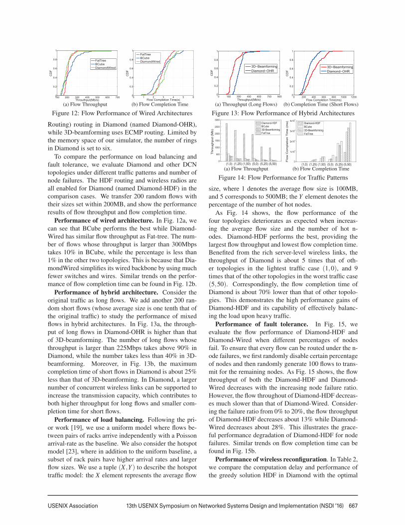
Figure 12: Flow Performance of Wired Architectures
Routing) routing in Diamond (named Diamond-OHR),while 3D-beamforming uses ECMP routing. Limited bythe memory space of our simulator, the number of ringsin Diamond is set to six.
To compare the performance on load balancing andfault tolerance, we evaluate Diamond and other DCNtopologies under different traffic patterns and number ofnode failures. The HDF routing and wireless radios areall enabled for Diamond (named Diamond-HDF) in thecomparison cases. We transfer 200 random flows withtheir sizes set within 200MB, and show the performanceresults of flow throughput and flow completion time.
Performance of wired architecture. In Fig. 12a, wecan see that BCube performs the best while Diamond-Wired has similar flow throughput as Fat-tree. The num-ber of flows whose throughput is larger than 300Mbpstakes 10% in BCube, while the percentage is less than1% in the other two topologies. This is because that Dia-mondWired simplifies its wired backbone by using muchfewer switches and wires. Similar trends on the perfor-mance of flow completion time can be found in Fig. 12b.
Performance of hybrid architecture. Consider theoriginal traffic as long flows. We add another 200 ran-dom short flows (whose average size is one tenth that ofthe original traffic) to study the performance of mixedflows in hybrid architectures. In Fig. 13a, the through-put of long flows in Diamond-OHR is higher than thatof 3D-beamforming. The number of long flows whosethroughput is larger than 225Mbps takes above 90% inDiamond, while the number takes less than 40% in 3D-beamforming. Moreover, in Fig. 13b, the maximumcompletion time of short flows in Diamond is about 25%less than that of 3D-beamforming. In Diamond, a largernumber of concurrent wireless links can be supported toincrease the transmission capacity, which contributes toboth higher throughput for long flows and smaller com-pletion time for short flows.
Performance of load balancing. Following the pri-or work [19], we use a uniform model where flows be-tween pairs of racks arrive independently with a Poissonarrival-rate as the baseline. We also consider the hotspotmodel [23], where in addition to the uniform baseline, asubset of rack pairs have higher arrival rates and largerflow sizes. We use a tuple (X ,Y ) to describe the hotspottraffic model: the X element represents the average flow
0 150 300 450 600 750 9000
0.2
0.4
0.6
0.8
1
Throughput(Mb/s)
CD
F
p
3D−BeamformingDiamond−OHR
(a) Throughput (Long Flows)
0 200 400 600 800 1000 12000
0.2
0.4
0.6
0.8
1
Flow Completion Time(ms)
CD
F
3D−BeamformingDiamond−OHR
(b) Completion Time (Short Flows)
Figure 13: Flow Performance of Hybrid Architectures
size, where 1 denotes the average flow size is 100MB,and 5 corresponds to 500MB; the Y element denotes thepercentage of the number of hot nodes.
As Fig. 14 shows, the flow performance of thefour topologies deteriorates as expected when increas-ing the average flow size and the number of hot n-odes. Diamond-HDF performs the best, providing thelargest flow throughput and lowest flow completion time.Benefited from the rich server-level wireless links, thethroughput of Diamond is about 5 times that of oth-er topologies in the lightest traffic case (1,0), and 9times that of the other topologies in the worst traffic case(5,50). Correspondingly, the flow completion time ofDiamond is about 70% lower than that of other topolo-gies. This demonstrates the high performance gains ofDiamond-HDF and its capability of effectively balanc-ing the load upon heavy traffic.
Performance of fault tolerance. In Fig. 15, weevaluate the flow performance of Diamond-HDF andDiamond-Wired when different percentages of nodesfail. To ensure that every flow can be routed under the n-ode failures, we first randomly disable certain percentageof nodes and then randomly generate 100 flows to trans-mit for the remaining nodes. As Fig. 15 shows, the flowthroughput of both the Diamond-HDF and Diamond-Wired decreases with the increasing node failure ratio.However, the flow throughout of Diamond-HDF decreas-es much slower than that of Diamond-Wired. Consider-ing the failure ratio from 0% to 20%, the flow throughputof Diamond-HDF decreases about 13% while Diamond-Wired decreases about 28%. This illustrates the grace-ful performance degradation of Diamond-HDF for nodefailures. Similar trends on flow completion time can befound in Fig. 15b.
Performance of wireless reconfiguration. In Table 2,we compare the computation delay and performance ofthe greedy solution HDF in Diamond with the optimal
668 13th USENIX Symposium on Networked Systems Design and Implementation (NSDI ’16) USENIX Association
5 10 15 200
100
200
300
400Th
roug
hput
(Mb)
Failure Degree (%)
Diamond-HDF Diamond-Wired
(a) Flow Throughput
5 10 15 200
1000
2000
3000
4000
Flow
Com
plet
ion
Tim
e (m
s)
Failure Degree (%)
Diamond-HDF Diamond-Wired
(b) Flow Completion TimeFigure 15: Flow Performance for Fault Tolerance
solution (named Full-ILP) of the HLBP problem. Weuse the ILP solver LINGO to compute the global optimalsolution of ILP for routing (we obtained the same result-s when using the ILP toolbox in MATLAB for calcula-tion). Limited by the memory constraint of LINGO, weevaluate the scales of Diamond with up to 5 rings whichcontains totally 60 racks and each rack holds 48 server-s. We can see that the computation delay of Full-ILPincreases quickly with the number of rings while HDFkeeps a stable and low computation delay around 30m-s. The tradeoff is HDF gets up to 15% gap on the per-formance of throughput and flow completion time whencompared with Full-ILP. For a practical network scalewithin 20 rings, Full-ILP can not provide the solutionin reasonable time, while HDF still achieves a low de-lay within 100ms, which is comparable to the feasiblescheduling overhead illustrated in [4].
8 Related WorkConventional data center: There exist prevalent hot
spots in hierarchical data centers [3, 15, 18, 39], whichlimits the DCN performance. Many DCN architectureshave been proposed to address the hot-spot problem intree-based data center networks. Some efforts [30–32]propose to construct a random networking topology toachieve smaller network diameter, less hot spots andhigher performance than state-of-art structured architec-tures. But the wiring and routing are quite challengingin a totally random wired network. In [16, 17], authorspropose to build the network recursively to efficiently e-liminate the structured bottleneck. However, the routingis restricted to follow its recursive structure, which doesnot consider the high dynamics in traffic demands andthus may lead to more hot spots.
Hybrid data center networking: Recent efforts turnto hybrid data center networking with flexible new net-working components (e.g., the optical circuit switches,60GHz wireless radios or FSO transceivers) to addressthe dynamic traffic demands [13,18,19,24,25,28,33,38].
Table 2: Performance of reconfigurationRing Delay (ms) Throughput Flow Completion Time
Flyway first illustrates the feasibility of applying 60GHzwireless technology in DCNs [18]. The work in [38]further enhances the Flyway performance by using theceiling reflector to bounce signals to avoid blocking onthe 2D plane. Using the same method, Firefly exploresthe feasibility of running free-space-optical (FSO) trans-missions in DCNs [19]. This method, however, requiresa height-restricted ceiling and also complete clearanceabove racks, which is infeasible in most data centers dueto the existence of air conditioning pipes and steel struc-tures above the racks [1]. Moreover, existing methodsonly considered the local performance improvement atthe rack level and part of network layers. In contrast,Diamond can run a larger number of network-wide wire-less links (either 60GHz or FSO) without involving anyengineering efforts to change the room plan above racks.Both wireless technologies can be applied in Diamondat the server level with different trade-offs: commodity60GHz antenna is much cheaper and smaller than FSOtransceivers while FSO has little interference footprintand longer transmission distance. With the decreasingcost of optical transceivers, FSO shows great promise torun in Diamond in the future.
9 ConclusionWe propose Diamond, a novel hybrid network architec-ture, to enable high capacity and seamless data transmis-sions over both wired and wireless network links. Specif-ically, we introduce the concept of Ring Reflection Space(RRS) to enable the wide deployment of wireless radiosat servers and high number of concurrent wireless trans-missions through low-cost multi-reflection over the met-al, and develop a precise reflection scheme to reduce thewireless interference inside an RRS. The rich wireless re-sources allow Diamond to flexibly configure the networktopology and form the transmission path to avoid cre-ating hot traffic spots while enabling transmissions overrandom network topology for low delay. We also provethe scalability of the proposed architecture. We imple-ment the proposed techniques over 60Ghz testbed anddemonstrate its functionality. Our results from extensivesimulations show that the cohesive structure of Diamondenables fine-grained and network-wide load balancing,effective routing and graceful fault-tolerance.
AcknowledgmentsThis work is supported by National Natural ScienceFoundation of China (no. 61120106008, 61422206), Ts-inghua National Laboratory for Information Science andTechnology (TNList). Xin Wang’s research is support-ed by NSF CNS 1526843, and Xiangyang Li’s researchis supported by NSF ECCS-1247944. We would like tothank our shepherd Alex C. Snoeren and the anonymousreviewers for their valuable feedback and suggestions.
USENIX Association 13th USENIX Symposium on Networked Systems Design and Implementation (NSDI ’16) 669
References[1] Google data center image. http://www.google.com/about/
datacenters/gallery/#/all.
[2] ABU-LIBDEH, H., COSTA, P., ROWSTRON, A., O’SHEA, G.,AND DONNELLY, A. Symbiotic routing in future data centers. InSIGCOMM (2011).
[3] AL-FARES, M., LOUKISSAS, A., AND VAHDAT, A. A scal-able, commodity data center network architecture. In SIGCOMM(2008).
[4] AL-FARES, M., RADHAKRISHNAN, S., RAGHAVAN, B.,HUANG, N., AND VAHDAT, A. Hedera: Dynamic flow schedul-ing for data center networks. In NSDI (2010).
[5] ALIZADEH, M., GREENBERG, A., MALTZ, D. A., PADHYE,J., PATEL, P., PRABHAKAR, B., SENGUPTA, S., AND SRIDHA-RAN, M. Data center tcp (dctcp). In SIGCOMM (2011).
[6] BASU, A., AND RIECKE, J. Stability issues in ospf routing. InSIGCOMM (2001).
[7] BENSON, T., AKELLA, A., AND MALTZ, D. A. Network trafficcharacteristics of data centers in the wild. In IMC (2010).
[8] BENSON, T., ANAND, A., AKELLA, A., AND ZHANG, M. Un-derstanding data center traffic characteristics. ACM SIGCOMMComputer Communication Review 40, 1 (2010), 92–99.
[9] CHEN, K., SINGLA, A., SINGH, A., RAMACHANDRAN, K., X-U, L., ZHANG, Y., WEN, X., AND CHEN, Y. Osa: an opticalswitching architecture for data center networks with unprecedent-ed flexibility. In NSDI (2012).
[10] CUI, Y., WANG, H., CHENG, X., LI, D., AND YLA-JAASKI,A. Dynamic scheduling for wireless data center networks. IEEETransactions on Parallel and Distributed Systems (TPDS) 24, 12(2013), 2365–2374.
[11] CURTIS, A. R., MOGUL, J. C., TOURRILHES, J., YALAGAN-DULA, P., SHARMA, P., AND BANERJEE, S. Devoflow: scalingflow management for high-performance networks. In SIGCOMM(2011).
[12] DE BRUIJN, N. G., AND ERDOS, P. A combinatorial prob-lem. Koninklijke Nederlandse Akademie v. Wetenschappen 49,49 (1946), 758–764.
[13] FARRINGTON, N., PORTER, G., RADHAKRISHNAN, S., BAZ-ZAZ, H. H., SUBRAMANYA, V., FAINMAN, Y., PAPEN, G.,AND VAHDAT, A. Helios: a hybrid electrical/optical switch ar-chitecture for modular data centers. In SIGCOMM (2011).
[14] GAREY, M. R., AND JOHNSON, D. S. Computers and in-tractability: A guide to the theory of np-completeness. WH Free-man & Co., San Francisco (1979), 61–62.
[15] GREENBERG, A., HAMILTON, J. R., JAIN, N., KANDULA, S.,KIM, C., LAHIRI, P., MALTZ, D. A., PATEL, P., AND SEN-GUPTA, S. Vl2: a scalable and flexible data center network. InSIGCOMM (2009).
[16] GUO, C., LU, G., LI, D., WU, H., ZHANG, X., SHI, Y., TIAN,C., ZHANG, Y., AND LU, S. Bcube: a high performance, server-centric network architecture for modular data centers. In SIG-COMM (2009).
[17] GUO, C., WU, H., TAN, K., SHI, L., ZHANG, Y., AND LU,S. Dcell: a scalable and fault-tolerant network structure for datacenters. In SIGCOMM (2008).
[18] HALPERIN, D., KANDULA, S., PADHYE, J., BAHL, P., ANDWETHERALL, D. Augmenting data center networks with multi-gigabit wireless links. In SIGCOMM (2011).
[19] HAMEDAZIMI, N., QAZI, Z., GUPTA, H., SEKAR, V., DAS,S. R., LONGTIN, J. P., SHAH, H., AND TANWER, A. Firefly: areconfigurable wireless data center fabric using free-space optics.In SIGCOMM (2014).
[20] KANDULA, S., SENGUPTA, S., GREENBERG, A., PATEL, P.,AND CHAIKEN, R. The nature of data center traffic: measure-ments & analysis. In SIGCOMM (2009).
[21] LI, X.-Y. Multicast capacity of wireless ad hoc networks.IEEE/ACM Transactions on Networking (TON) 17, 3 (2009),950–961.
[22] LI, X.-Y., TANG, S.-J., AND FRIEDER, O. Multicast capacityfor large scale wireless ad hoc networks. In MOBICOM (2007).
[23] LI, X.-Y., AND WANG, Y. Simple approximation algorithms andptass for various problems in wireless ad hoc networks. Journalof Parallel and Distributed Computing 66, 4 (2006), 515–530.
[24] LIU, H., LU, F., FORENCICH, A., KAPOOR, R., TEWARI, M.,VOELKER, G. M., PAPEN, G., SNOEREN, A. C., AND PORTER,G. Circuit switching under the radar with reactor. In NSDI(2014).
[25] LIU, Y. J., GAO, P. X., WONG, B., AND KESHAV, S. Quartz: anew design element for low-latency dcns. In SIGCOMM (2014).
[26] MCKEOWN, N., ANDERSON, T., BALAKRISHNAN, H.,PARULKAR, G., PETERSON, L., REXFORD, J., SHENKER, S.,AND TURNER, J. Openflow: enabling innovation in campus net-works. ACM SIGCOMM Computer Communication Review 38,2 (2008), 69–74.
[27] PERRY, J., OUSTERHOUT, A., BALAKRISHNAN, H., SHAH, D.,AND FUGAL, H. Fastpass: A centralized zero-queue datacenternetwork. In SIGCOMM (2014).
[28] PORTER, G., STRONG, R., FARRINGTON, N., FORENCICH, A.,CHEN-SUN, P., ROSING, T., FAINMAN, Y., PAPEN, G., ANDVAHDAT, A. Integrating microsecond circuit switching into thedata center. In SIGCOMM (2013).
[29] SHIN, J.-Y., SIRER, E. G., WEATHERSPOON, H., ANDKIROVSKI, D. On the feasibility of completely wirelesss dat-acenters. IEEE/ACM Transactions on Networking (TON) 21, 5(2013), 1666–1679.
[30] SHIN, J.-Y., WONG, B., AND SIRER, E. G. Small-world dat-acenters. In Proceedings of the 2nd ACM Symposium on CloudComputing (2011), ACM, p. 2.
[31] SINGLA, A., GODFREY, P. B., AND KOLLA, A. High through-put data center topology design. In NSDI (2014).
[32] SINGLA, A., HONG, C.-Y., POPA, L., AND GODFREY, P. B.Jellyfish: Networking data centers randomly. In NSDI (2012).
[33] WANG, G., ANDERSEN, D. G., KAMINSKY, M., PAPAGIAN-NAKI, K., NG, T., KOZUCH, M., AND RYAN, M. c-through:Part-time optics in data centers. In SIGCOMM (2010).
[34] WANG, W., WANG, Y., LI, X.-Y., SONG, W.-Z., ANDFRIEDER, O. Efficient interference-aware tdma link schedulingfor static wireless networks. In MOBICOM (2006).
[35] WANG, Y., WANG, W., LI, X.-Y., AND SONG, W.-Z.Interference-aware joint routing and tdma link scheduling forstatic wireless networks. IEEE Transactions on Parallel and Dis-tributed Systems (TPDS) 19, 12 (2008), 1709–1726.
[36] XU, X., LI, X.-Y., WAN, P.-J., AND TANG, S. Efficien-t scheduling for periodic aggregation queries in multihop sensornetworks. IEEE/ACM Transactions on Networking (TON) 20, 3(2012), 690–698.
[37] YU, M., GREENBERG, A. G., MALTZ, D. A., REXFORD, J.,YUAN, L., KANDULA, S., AND KIM, C. Profiling network per-formance for multi-tier data center applications. In NSDI (2011).
[38] ZHOU, X., ZHANG, Z., ZHU, Y., LI, Y., KUMAR, S., VAHDAT,A., ZHAO, B. Y., AND ZHENG, H. Mirror mirror on the ceiling:flexible wireless links for data centers. In SIGCOMM (2012).
[39] ZHU, Y., ZHOU, X., ZHANG, Z., ZHOU, L., VAHDAT, A.,ZHAO, B. Y., AND ZHENG, H. Cutting the cord: a robust wire-less facilities network for data centers. In MOBICOM (2014).