20
Diaphragm valves GF Piping Systems Tips and Tricks
Diaphragm valves
GF Piping Systems
Tips and Tricks

Contents
1 General information about this document ................................................................................ 2
1.1 Diaphragm valves 5 series overview .................................................................................... 2
1.2 Construction DIASTAR ........................................................................................................ 4
1.3 Construction Type 604/605 .................................................................................................. 4
1.4 Pressure ranges and spring packages DIASTAR ................................................................. 5
2 Turn the air connections at the DIASTAR ................................................................................. 6
3 Changing the diaphragm DIASTAR DN15-DN50 ....................................................................... 7
3.1 Tool ...................................................................................................................................... 8
3.2 Instructions for replacing the diaphragm .............................................................................. 9
4 Changing the diaphragm DIASTAR DN65-DN150 ................................................................... 11
4.1 Replacing the diaphragm ................................................................................................... 11
5 Accessories .............................................................................................................................. 14
5.1 Stroke limiter and manual override ..................................................................................... 14
5.2 Electrical feedback ............................................................................................................. 14
5.3 Electro-pneumatic positioner - DSR ................................................................................... 15
5.4 Pilot valve .......................................................................................................................... 15
6 Spare Parts ............................................................................................................................... 17
Annex ............................................................................................................................................... 18

Tips and tricks – diaphragm valve
General information about this document
08.2016, GF Piping Systems 2
1 General information about this document
This document is valid only as a supplement to the existing GF documentation. The remarks and details in the
general user manual are still to be followed.
The following pages should provide support concerning the handling of GF diaphragm valve. Further information
can also be found under www.gfps.com/dv or in the GF planning fundamentals industry.
1.1 Diaphragm valves 5 series overview
Manually operated
General Type 514 515 517 519
Description True Union Spigot ends Flange version 3-Way
Dimension DN15-DN50
Pressure level PN10/ PN16 *
Materials PVC-U
PVC-C
ABS
PP-H
PP-n
PVDF
PVDF-HP
Connection type Sockets
Spigot
Flange
Threaded socket
Diaphragm materials
EPDM
PTFE/EPDM
PTFE/FPM
FPM
NBR
Accessories Feedback electric
* See pressure-temperature diagram in the respective data sheet
Tips and tricks – diaphragm valve
General information about this document
08.2016, GF Piping Systems 3
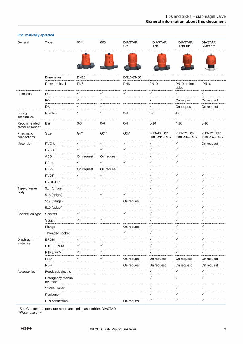
Pneumatically operated
General Type 604 605 DIASTAR Six
DIASTAR Ten
DIASTAR TenPlus
DIASTAR Sixteen**
Dimension DN15 DN15-DN50
Pressure level PN6 PN6 PN10 PN10 on both sides
PN16
Functions FC
FO On request On request
DA On request On request
Spring assemblies
Number 1 1 3-6 3-6 4-6 6
Recommended pressure range*
Bar 0-6 0-6 0-6 0-10 4-10 8-16
Pneumatic connections
Size G¼“ G¼“ G⅛“ to DN40: G⅛“ from DN40: G¼“
to DN32: G⅛“ from DN32: G¼“
to DN32: G⅛“ from DN32: G¼“
Materials PVC-U On request
PVC-C
ABS On request On request
PP-H
PP-n On request On request
PVDF
PVDF-HP
Type of valve body
514 (union)
515 (spigot)
517 (flange) On request
519 (spigot)
Connection type Sockets
Spigot
Flange On request
Threaded socket
Diaphragm materials
EPDM
PTFE/EPDM
PTFE/FPM
FPM On request On request On request On request
NBR On request On request On request On request
Accessories Feedback electric
Emergency manual override
Stroke limiter
Positioner
Bus connection On request
* See Chapter 1.4. pressure range and spring assemblies DIASTAR **Water use only
Tips and tricks – diaphragm valve
General information about this document
08.2016, GF Piping Systems 4
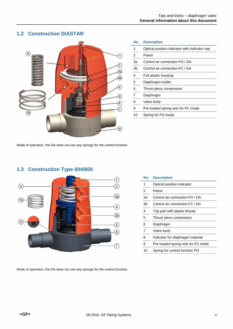
1.2 Construction DIASTAR
No. Description
1 Optical position indicator with indicator cap
2 Piston
3a Control air connection FO / DA
3b Control air connection FC / DA
4 Full plastic housing
5 Diaphragm holder
6 Thrust piece compressor
7 Diaphragm
8 Valve body
9 Pre-loaded spring sets for FC mode
10 Spring for FO mode
Mode of operation, the DA does not use any springs for the control function
1.3 Construction Type 604/605
No. Description
1 Optical position indicator
2 Piston
3a Control air connection FO / DA
3b Control air connection FC / DA
4 Top part with plastic thread
5 Thrust piece compressor
6 Diaphragm
7 Valve body
8 Indicator for diaphragm material
9 Pre-loaded spring sets for FC mode
10 Spring for control function FO
Mode of operation, the DA does not use any springs for the control function
Tips and tricks – diaphragm valve
General information about this document
08.2016, GF Piping Systems 5
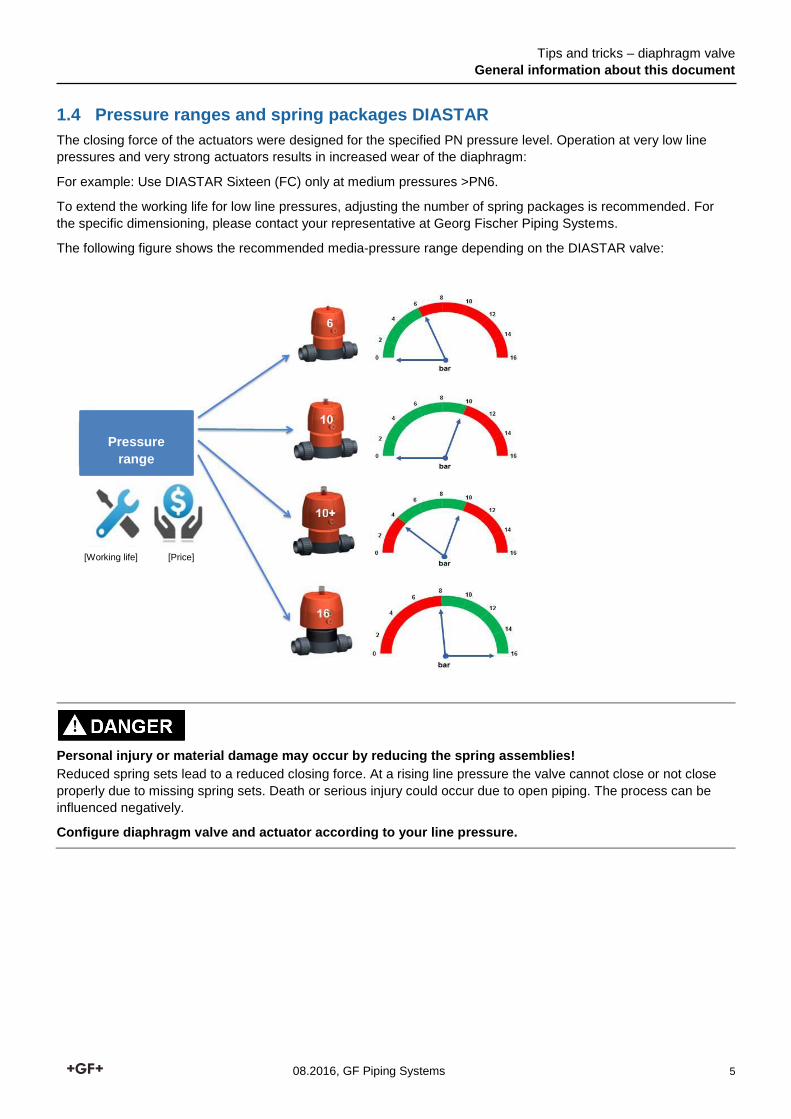
1.4 Pressure ranges and spring packages DIASTAR
The closing force of the actuators were designed for the specified PN pressure level. Operation at very low line
pressures and very strong actuators results in increased wear of the diaphragm:
For example: Use DIASTAR Sixteen (FC) only at medium pressures >PN6.
To extend the working life for low line pressures, adjusting the number of spring packages is recommended. For
the specific dimensioning, please contact your representative at Georg Fischer Piping Systems.
The following figure shows the recommended media-pressure range depending on the DIASTAR valve:
Personal injury or material damage may occur by reducing the spring assemblies!
Reduced spring sets lead to a reduced closing force. At a rising line pressure the valve cannot close or not close
properly due to missing spring sets. Death or serious injury could occur due to open piping. The process can be
influenced negatively.
Configure diaphragm valve and actuator according to your line pressure.
Pressure
range
[Price] [Working life]
Tips and tricks – diaphragm valve
Turn the air connections at the DIASTAR
08.2016, GF Piping Systems 6
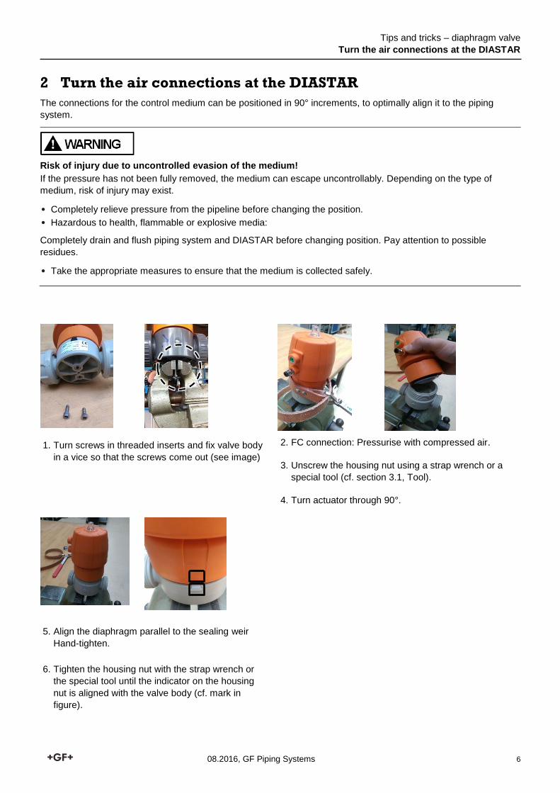
2 Turn the air connections at the DIASTAR
The connections for the control medium can be positioned in 90° increments, to optimally align it to the piping
system.
Risk of injury due to uncontrolled evasion of the medium!
If the pressure has not been fully removed, the medium can escape uncontrollably. Depending on the type of
medium, risk of injury may exist.
• Completely relieve pressure from the pipeline before changing the position.
• Hazardous to health, flammable or explosive media:
Completely drain and flush piping system and DIASTAR before changing position. Pay attention to possible
residues.
• Take the appropriate measures to ensure that the medium is collected safely.
1. Turn screws in threaded inserts and fix valve body
in a vice so that the screws come out (see image)
2. FC connection: Pressurise with compressed air.
3. Unscrew the housing nut using a strap wrench or a
special tool (cf. section 3.1, Tool).
4. Turn actuator through 90°.
5. Align the diaphragm parallel to the sealing weir
Hand-tighten.
6. Tighten the housing nut with the strap wrench or
the special tool until the indicator on the housing
nut is aligned with the valve body (cf. mark in
figure).
Tips and tricks – diaphragm valve
Changing the diaphragm DIASTAR DN15-DN50
08.2016, GF Piping Systems 7
3 Changing the diaphragm DIASTAR DN15-DN50
This chapter describes the changing of a diaphragm.
It is possible to change the diaphragm whether the valve is installed or not.
Type and composition of the medium, pressure and temperature can significantly
influence the working life of the diaphragm. The inspection intervals are adapted to the
particular application requirements.
Maintenance plan
Maintenance interval Maintenance task
Regularly Check the connection between top part and valve body for leakage
1 - 2 times a year Operate to check functionality of permanently open or closed diaphragm valves
100,000 operations with less than 10 bar nominal pressure with 20°C and water DIASTAR Ten/ TenPlus
Perform visual inspection of the valve body Remove the actuator and check diaphragm for damage Change diaphragm in case of damage
50,000 operations with more than 10 bar nominal pressure with 20°C and water DIASTAR Sixteen
Perform visual inspection of the valve body Remove the actuator and check diaphragm for damage Change diaphragm in case of damage
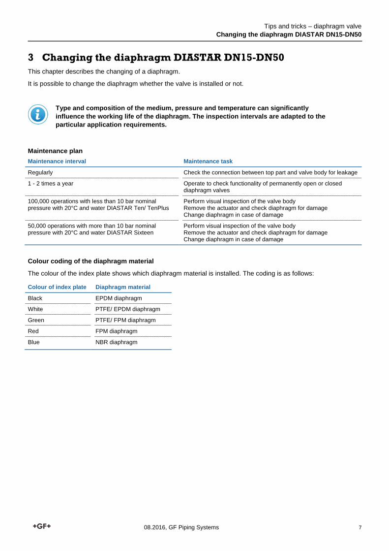
Colour coding of the diaphragm material
The colour of the index plate shows which diaphragm material is installed. The coding is as follows:
Colour of index plate Diaphragm material
Black EPDM diaphragm
White PTFE/ EPDM diaphragm
Green PTFE/ FPM diaphragm
Red FPM diaphragm
Blue NBR diaphragm

Tips and tricks – diaphragm valve
Changing the diaphragm DIASTAR DN15-DN50
08.2016, GF Piping Systems 8
3.1 Tool
The following material is required for a change of diaphragm:
• Strap wrench (EasyGrip) or special open-end wrench
• Tip: Use screw clamp and pipe piece for simplified disassembly
3.1.1 Strap wrench EasyGrip
EasyGrip is a strap wrench for pulling and releasing round screw connections.
This tool enables the safe screwing of the housing nut and a quick
maintenance of all GF diaphragm valves.
EasyGrip can be used for all dimensions of the whole range of the diaphragm
valves (DN15-DN50).
No. 198 154 019
3.1.2 Special wrench (GF)
For more frequent maintenance a dimension-dependent special wrench can
be used. By using this tool, the maintenance on a diaphragm valve can be
carried out efficiently.
The wrench with the following code number can be used for hand and
pneumatic valves:
DN 15 29 25 32 40 50
No 198 154 012 198 154 013 198 154 014 198 154 015 198 154 016 198 154 017
Hook wrench
Type 604/605
No. 700 278 354
Tips and tricks – diaphragm valve
Changing the diaphragm DIASTAR DN15-DN50
08.2016, GF Piping Systems 9
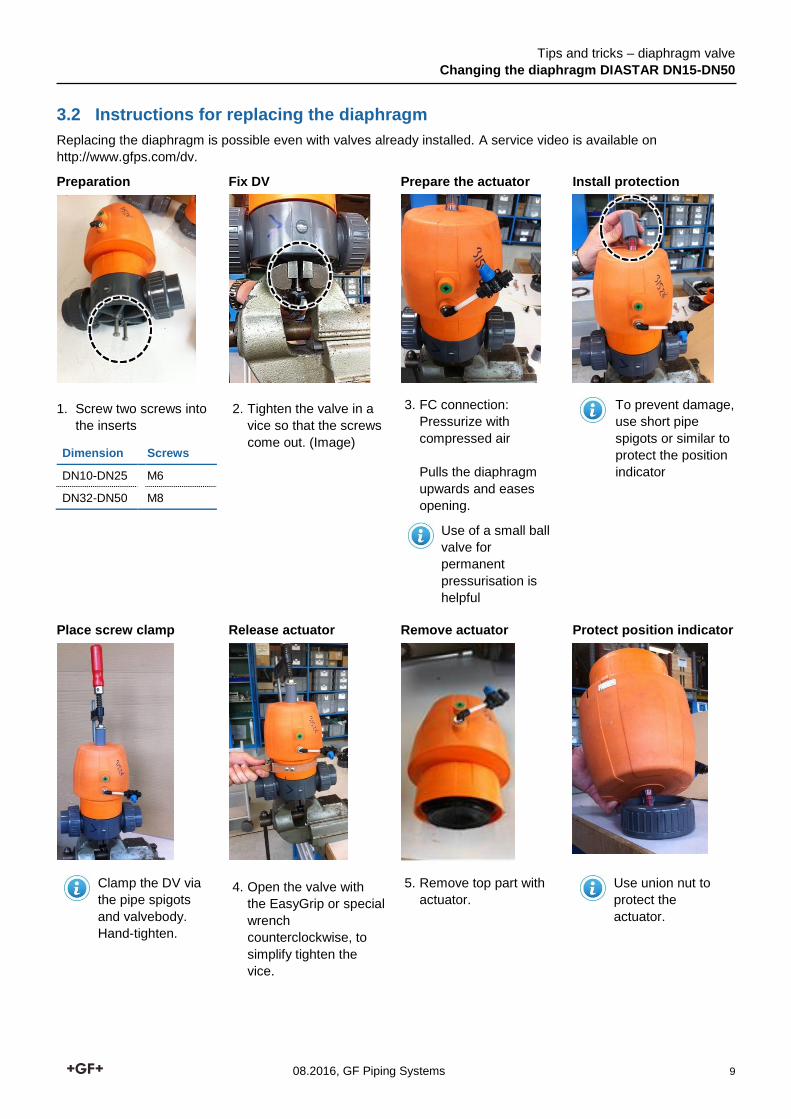
3.2 Instructions for replacing the diaphragm
Replacing the diaphragm is possible even with valves already installed. A service video is available on
http://www.gfps.com/dv.
Preparation Fix DV Prepare the actuator Install protection
1. Screw two screws into
the inserts
Dimension Screws
DN10-DN25 M6
DN32-DN50 M8
2. Tighten the valve in a
vice so that the screws
come out. (Image)
3. FC connection:
Pressurize with
compressed air
Pulls the diaphragm
upwards and eases
opening.
Use of a small ball
valve for
permanent
pressurisation is
helpful
To prevent damage,
use short pipe
spigots or similar to
protect the position
indicator
Place screw clamp Release actuator Remove actuator Protect position indicator
Clamp the DV via
the pipe spigots
and valvebody.
Hand-tighten.
4. Open the valve with
the EasyGrip or special
wrench
counterclockwise, to
simplify tighten the
vice.
5. Remove top part with
actuator. Use union nut to
protect the
actuator.

Tips and tricks – diaphragm valve
Changing the diaphragm DIASTAR DN15-DN50
08.2016, GF Piping Systems 10
Replace diaphragm Replace the index plate Screw on the actuator Tighten the actuator
6. Unscrew old
diaphragm
7. Screw in the new
diaphragm hand-tight.
8. Turn back the
diaphragm again at
least 90° / maximum
360°
9. Realign the sealing
bead of the diaphragm
parallel to the sealing
weir. In doing this,
position the lugs of the
diaphragm precisely
between the narrow
guide groove of the
inner housing.
10. Change the index plate
at the valve body
11. Screw the upper part of
the valve back onto the
valve body.
Pay attention to correct
position of the sealing
bead.
12. Using the EasyGrip or
special wrench pull back
to the position. (Position
indicator of the housing
nut aligns with the index
plate)
Type 604/605
Use hook key Pressurise the FC
connection with
compressed air
For changing the
diaphragm, see the
description DIASTAR
Steps 6-10
Screw the upper part of
the valve back onto the
valve body. Pay attention
to correct position of the
sealing bead.
Pull back to the position
using the hook key.
(Semicircular position
indicator of the housing
nut aligns with the index
plate)

Tips and tricks – diaphragm valve
Changing the diaphragm DIASTAR DN65-DN150
08.2016, GF Piping Systems 11
4 Changing the diaphragm DIASTAR DN65-DN150
In the following chapters, replacing the diaphragm, with large DIASTAR dimensions is described.
Risk of injury due to uncontrolled evasion of the medium!
If the pressure has not been fully removed, the medium can escape uncontrollably. Depending on the type of
medium, risk of injury may exist.
• Completely relieve pressure from the pipeline before changing the position.
• Hazardous to health, flammable or explosive media:
Completely drain and flush piping system and DIASTAR before changing position. Pay attention to possible
residues.
• Take the appropriate measures to ensure that the medium is collected safely.
Replacement of PTFE diaphragm with backing diaphragm!
Personal injury or material damage through uncontrolled leakage or continued flow from the medium pipe or
valve.
• Using PTFE diaphragm with rear position diaphragm EPDM or FPM:
Make sure that both diaphragms are replaced.
4.1 Replacing the diaphragm
Different connections of diaphragms on the compressor piece; depending on the material
and dimension. If the diaphragm material was to be changed, also replace the
compressor!
EPDM diaphragm with thread connection PTFE diaphragm with bayonet connection

Tips and tricks – diaphragm valve
Changing the diaphragm DIASTAR DN65-DN150
08.2016, GF Piping Systems 12
FO and DA actuator:
Use compressed air to
pressurize the compressor
(description see
diaphragm replacement)
1. Unscrew the protection cap of the position indicator.
2. Turn around the diaphragm valve and place on a union coupling nut to prevent damage to the position
indicator.
3. Unscrew the screws of the valve body.
4. Invert the diaphragm and unscrew it counterclockwise.

Tips and tricks – diaphragm valve
Changing the diaphragm DIASTAR DN65-DN150
08.2016, GF Piping Systems 13
5. Install a new diaphragm in the same position as the old diaphragm
• Place the actuator straight up for the first rotations, this is so that the grub screw of the diaphragm holder can
grip the diaphragm.
• Install the diaphragm hand tight clockwise.
• Turn back the diaphragm again at least 90° / maximum 360°.
• Realign the sealing bead of the diaphragm parallel to the sealing weir. In doing this, position the butt strap of
the diaphragm between the narrow guide groove (recess) of the inner housing.
6. Assemble in reverse order
Torque housing screws:
Dimension Torque
DN65 25 Nm
DN80 30 Nm
DN100 30 Nm
DN150 40 Nm
Tips and tricks – diaphragm valve
Accessories
08.2016, GF Piping Systems 14
5 Accessories
The respective accessories are not suitable for all types manual or pneumatic valves. Examination of the
respective specifications is strongly recommended. The information in this document should provide an overview of
available accessories and the respective versions.
5.1 Stroke limiter and manual override
The stroke limiter is suitable only for DIASTAR valves and is used for the mechanical flow limitation. In addition, the
stroke limiter can be used as an emergency manual override. For information on the respective stroke of the DV,
please refer to the Annex.
For DIASTAR Ten, Ten Plus and Sixteen
Stroke limiter and emergency manual override
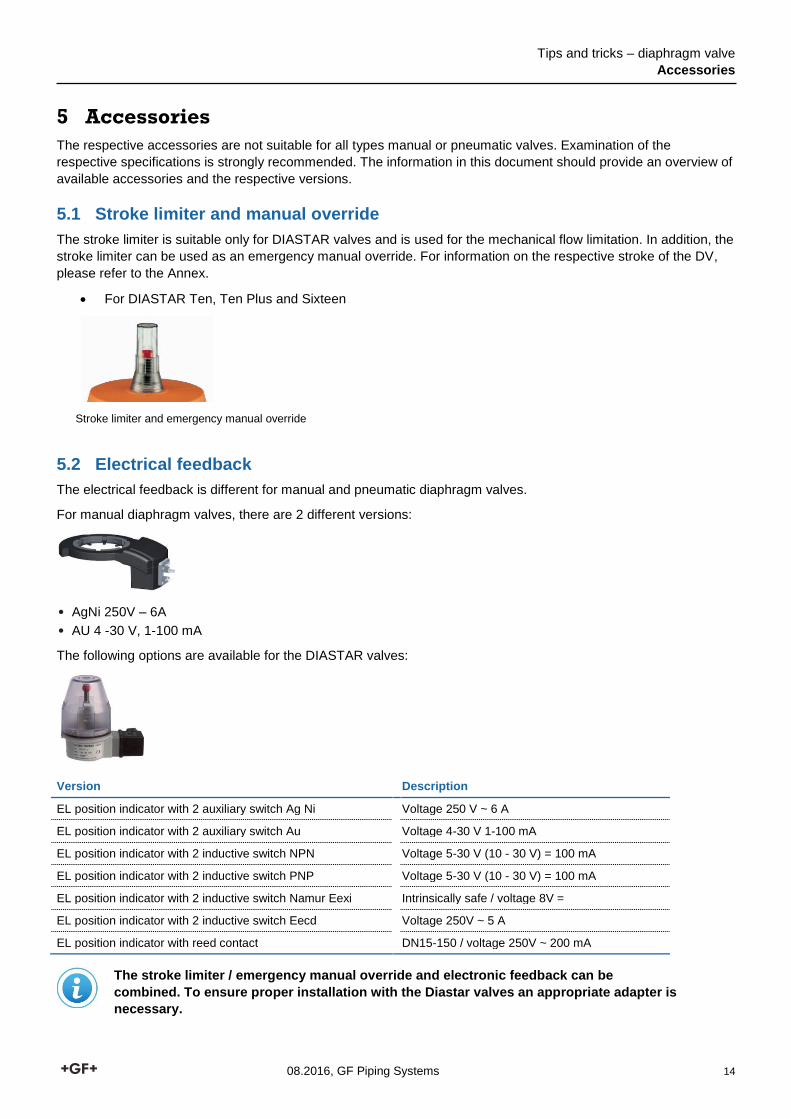
5.2 Electrical feedback
The electrical feedback is different for manual and pneumatic diaphragm valves.
For manual diaphragm valves, there are 2 different versions:
• AgNi 250V – 6A
• AU 4 -30 V, 1-100 mA
The following options are available for the DIASTAR valves:
Version Description
EL position indicator with 2 auxiliary switch Ag Ni Voltage 250 V ~ 6 A
EL position indicator with 2 auxiliary switch Au Voltage 4-30 V 1-100 mA
EL position indicator with 2 inductive switch NPN Voltage 5-30 V (10 - 30 V) = 100 mA
EL position indicator with 2 inductive switch PNP Voltage 5-30 V (10 - 30 V) = 100 mA
EL position indicator with 2 inductive switch Namur Eexi Intrinsically safe / voltage 8V =
EL position indicator with 2 inductive switch Eecd Voltage 250V ~ 5 A
EL position indicator with reed contact DN15-150 / voltage 250V ~ 200 mA
The stroke limiter / emergency manual override and electronic feedback can be
combined. To ensure proper installation with the Diastar valves an appropriate adapter is
necessary.

Tips and tricks – diaphragm valve
Accessories
08.2016, GF Piping Systems 15
5.3 Electro-pneumatic positioner - DSR
Type DSR 100 – DN15-50
Type DSR 101 – DN65-150
Available also with optical position indicator.
• Installation on pneumatic control valves
• Linear and rotary actuators
• Nominal stroke 3 - 28 mm
• Self-learning
• Input signal 4 - 20 mA
• 24 V DC
Electro-pneumatic positioner - DSR
5.4 Pilot valve
Various pilot valves are available depending on the requirement:
Type Description
PV 94 3/2-way valve with compressed air connection G1/8 or hose connector (push - in)
PV 95 3/2-way valve with compressed air connection G1/4
PV 2000 3/2-way and 5/2-way valve Connection module AS-interface or Profibus interface
MNL 532 Version for 3/2-way and 5/2-way valves Using a Namur connection plate
Type PV94 Type PV95 Type PV2000 Type MNL 532

Tips and tricks – diaphragm valve
Accessories
08.2016, GF Piping Systems 16
Namur connection plate
If you want to use a NAMUR pilot solenoid valve we offer connection plates. The connection plate is mounted
between the actuator and the pilot solenoid valve.
Namur connection plate
Mounting blocks PP
The mounting plates are designed to allow differently sized manual an pneumatic diaphragm valves to be aligned
on the same pipe centre line by equalising the different heights from the base to the centre line of the pipe. The
mounting blocks can be plugged together to achieve the desired height.
The mounting blocks can be combined as follows:
DN15-DN25: Mounting block 1 directly on the valve, mounting plate 2 and 3 for additional height
equalisation
DN32-DN50: Mounting block 4 directly on the valve, mounting plate 5 for additional height equalisation
Mounting blocks PP
Tips and tricks – diaphragm valve
Spare Parts
08.2016, GF Piping Systems 17
6 Spare Parts
Various spare parts are available for the GF diaphragm valve range of products:
• Upper parts for hand operated valves
• Actuators for pneumatic valves
• Valve bodies
• Sealing kits
• Diaphragm
Other spare parts are available depending on the type and dimension. Please check GF product catalogue for
further options.
Tips and tricks – diaphragm valve
Annex
08.2016, GF Piping Systems 18
Annex
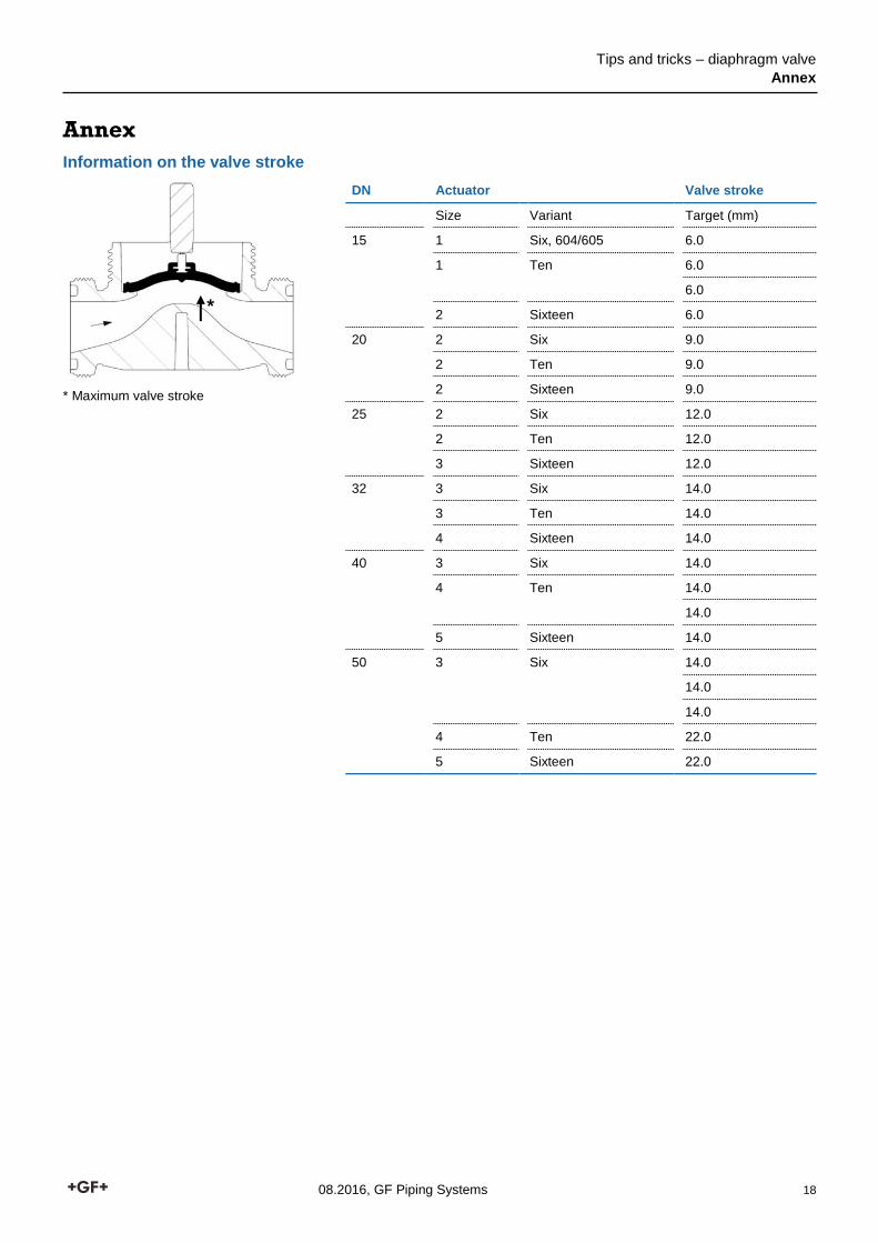
Information on the valve stroke
* Maximum valve stroke
DN Actuator Valve stroke
Size Variant Target (mm)
15 1 Six, 604/605 6.0
1 Ten 6.0
6.0
2 Sixteen 6.0
20 2 Six 9.0
2 Ten 9.0
2 Sixteen 9.0
25 2 Six 12.0
2 Ten 12.0
3 Sixteen 12.0
32 3 Six 14.0
3 Ten 14.0
4 Sixteen 14.0
40 3 Six 14.0
4 Ten 14.0
14.0
5 Sixteen 14.0
50 3 Six 14.0
14.0
14.0
4 Ten 22.0
5 Sixteen 22.0
*

GF Piping Systems
GFDO_6458_4 (08.16)
© Georg Fischer Piping Systems Ltd
CH-8201 Schaffhausen/Switzerland, 2016
Worldwide at HomeOur sales companies and representatives ensure local customer support in over 100 countries
The technical data are not binding. They neither constitute expressly warranted characteristics nor guaranteed properties nor a guaranteed durability. They are subject to modification. Our General Terms of Sale apply.
Argentina / Southern South AmericaGeorg Fischer Central Plastics Sudamérica S.R.L.Buenos Aires, ArgentinaPhone +54 11 4512 02 [email protected]/ar
AustraliaGeorge Fischer Pty LtdRiverwood NSW 2210 AustraliaPhone +61 (0) 2 9502 8000 [email protected]/au
AustriaGeorg Fischer Rohrleitungssysteme GmbH3130 HerzogenburgPhone +43 (0) 2782 856 [email protected]/at
Belgium / LuxembourgGeorg Fischer NV/SA1070 Bruxelles/BrüsselPhone +32 (0) 2 556 40 [email protected]/be
BrazilGeorg Fischer Sist. de Tub. Ltda.04571-020 São Paulo/SPPhone +55 (0)11 5525 [email protected]/br
CanadaGeorg Fischer Piping Systems LtdMississauga, ON L5T 2B2Phone +1 (905) 670 8005Fax +1 (905) 670 [email protected]/ca
ChinaGeorg Fischer Piping Systems Ltd Shanghai 201319Phone +86 21 3899 3899 [email protected]/cn
Denmark / IcelandGeorg Fischer A/S2630 TaastrupPhone +45 (0) 70 22 19 [email protected]/dk
FinlandGeorg Fischer AB01510 VANTAAPhone +358 (0) 9 586 58 25 Fax +358 (0) 9 586 58 [email protected]/fi
FranceGeorg Fischer SAS95932 Roissy Charles de Gaulle CedexPhone +33 (0) 1 41 84 68 [email protected]/fr
GermanyGeorg Fischer GmbH73095 Albershausen Phone +49 (0) 7161 [email protected]/de
IndiaGeorg Fischer Piping Systems Ltd400 083 MumbaiPhone +91 224007 [email protected]/in
IndonesiaGeorge Fischer Pte Ltd – Representative OfficePhone +62 21 2900 8564Fax +62 21 2900 [email protected]/sg
ItalyGeorg Fischer S.p.A.20063 Cernusco S/N (MI)Phone +39 02 921 [email protected]/it
JapanGeorg Fischer Ltd556-0011 Osaka, Phone +81 (0) 6 6635 [email protected]/jp
KoreaGF Piping SystemsGeorg Fischer Korea Co., Ltd.Unit 2501, U-Tower120 HeungdeokJungang-ro (Yeongdeok-dong) Giheung-gu, Yongin-si, Gyeonggi-do, KoreaPhone: +82 31 8017 1450Fax : +82 31 217 [email protected]/kr
MalaysiaGeorge Fischer (M) Sdn. Bhd.40460 Shah Alam, Selangor Darul EhsanPhone +60 (0) 3 5122 5585Fax +603 5122 [email protected]/my
Mexico / Northern Latin AmericaGeorg Fischer S.A. de C.V.Apodaca, Nuevo LeonCP66636 MexicoPhone +52 (81) 1340 8586Fax +52 (81) 1522 [email protected]/mx
Middle EastGeorg Fischer Piping Systems (Switzerland) LtdDubai, United Arab EmiratesPhone +971 4 289 49 [email protected]/int
NetherlandsGeorg Fischer N.V.8161 PA EpePhone +31 (0) 578 678 222 [email protected]/nl
NorwayGeorg Fischer AS1351 Rud Phone +47 67 18 29 [email protected]/no
PhilippinesGeorge Fischer Pte Ltd Representative OfficePhone +632 571 2365 Fax +632 571 [email protected]/sg
PolandGeorg Fischer Sp. z o.o.05-090 Sekocin Nowy Phone +48 (0) 22 31 31 0 50 [email protected]/pl
RomaniaGeorg Fischer Piping Systems (Switzerland) Ltd020257 Bucharest - Sector 2Phone +40 (0) 21 230 53 [email protected]/int
RussiaGeorg Fischer Piping Systems (Switzerland) LtdMoscow 125040Phone +7 495 748 11 [email protected]/ru
SingaporeGeorge Fischer Pte Ltd11 Tampines Street 92, #04-01/07528 872 SingaporePhone +65 6747 0611Fax +65 6747 [email protected]/sg
Spain / PortugalGeorg Fischer S.A.28046 MadridPhone +34 (0) 91 781 98 [email protected]/es
SwedenGeorg Fischer AB117 43 StockholmPhone +46 (0) 8 506 775 [email protected]/se
SwitzerlandGeorg Fischer Rohrleitungssysteme (Schweiz) AG8201 SchaffhausenPhone +41 (0) 52 631 30 [email protected]/ch
TaiwanGeorg Fischer Co., LtdSan Chung Dist., New Taipei CityPhone +886 2 8512 2822Fax +886 2 8512 2823www.gfps.com/tw
United Kingdom / IrelandGeorge Fischer Sales LimitedCoventry, CV2 2STPhone +44 (0) 2476 535 [email protected]/uk
USA / CaribbeanGeorg Fischer LLC9271 Jeronimo Road92618 Irvine, CAPhone +1 714 731 88 00 Fax +1 714 731 62 [email protected]/us
International Georg Fischer Piping Systems (Switzerland) Ltd8201 Schaffhausen/SwitzerlandPhone +41 (0) 52 631 30 03Fax +41 (0) 52 631 28 [email protected]/int
www.gfps.com


