60
897N0547D (010-113-90) DICOM Conformance Statement CR Console (Standard) Copyright FUJIFILM Corporation, Japan June 2007 10th Edition
| Date post: | 11-Jun-2018 |
| Category: |
Documents |
| Upload: | nguyenliem |
| View: | 232 times |
| Download: | 0 times |

897N0547D (010-113-90)
DICOM Conformance Statement
CR Console
(Standard)
Copyright FUJIFILM Corporation, Japan
June 2007 10th Edition
CR Console (Standard) DICOM Conformance Statement
010-113-90 06.2007
Revision History
History Date Revision Description
1st Edition April, 2002
2nd Edition October, 2002
3rd Edition January, 2003
4th Edition May, 2003
5th Edition April, 2004
6th Edition July, 2005
7th Edition June, 2006
8th Edition October, 2006 The corporate name was changed.
9th Edition March, 2007
10th Edition June, 2007

CR Console (Standard) DICOM Conformance Statement
010-113-60 06.2006
1
CONTENTS
1. Introduction ..............................................................................................................................5 2. Implementation Mode ..............................................................................................................5
2.1 Data Flow Diagram.............................................................................................................6 2.2 Functional Definitions of Application Entities ......................................................................7 2.3 Sequencing of Real World Activities ...................................................................................7
3. AE Specification.......................................................................................................................8 3.1 CR Console AE Specification .............................................................................................8
3.1.1 Association Establishment Policies ..............................................................................8 3.1.1.1 General...................................................................................................................8 3.1.1.2 Number of Associations..........................................................................................8 3.1.1.3 Asynchronous Nature .............................................................................................8 3.1.1.4 Implementation ID information................................................................................8
3.1.2 Association Initiation Policy ..........................................................................................9 3.1.2.1 Send Image(s) to Remote AE.................................................................................9
3.1.2.1.1 Associated Real-World Activity .........................................................................9 3.1.2.1.2 Proposed Presentation Context ........................................................................9 3.1.2.1.3 SOP Specific Conformance ..............................................................................9
3.1.2.2 Print Image(s) .........................................................................................................9 3.1.2.2.1 Associated Real-World Activity .........................................................................9 3.1.2.2.2 Proposed Presentation Context ......................................................................10 3.1.2.2.3 SOP Specific Conformance ............................................................................10
3.1.2.3 Query/Retrieve Image(s) ......................................................................................10 3.1.2.3.1 Associated Real-World Activity .......................................................................10 3.1.2.3.2 Proposed Presentation Context ......................................................................10 3.1.2.3.3 SOP Specific Conformance ............................................................................10
3.1.2.4 Get Worklist ..........................................................................................................11 3.1.2.4.1 Associated Real-World Activity .......................................................................11 3.1.2.4.2 Proposed Presentation Context ......................................................................11 3.1.2.4.3 SOP Specific Conformance ............................................................................11
3.1.2.5 Inform Procedure State.........................................................................................12 3.1.2.5.1 Associated Real-World Activity .......................................................................12 3.1.2.5.2 Proposed Presentation Context ......................................................................12 3.1.2.5.3 SOP Specific Conformance ............................................................................12
3.1.2.6 Storage Commitment............................................................................................12 3.1.2.6.1 Associated Real-World Activity .......................................................................12 3.1.2.6.2 Proposed Presentation Context ......................................................................12
CR Console (Standard) DICOM Conformance Statement
010-113-60 06.2006
2
3.1.2.6.3 SOP Specific Conformance............................................................................ 13 3.1.2.7 Verification ........................................................................................................... 13
3.1.2.7.1 Associated Real-World Activity....................................................................... 13 3.1.2.7.2 Proposed Presentation Context...................................................................... 13 3.1.2.7.3 SOP Specific Conformance............................................................................ 13
3.1.3 Association Acceptance Policy .................................................................................. 14 3.1.3.1 Verification Request from Remote AE.................................................................. 14
3.1.3.1.1 Associated Real-World Activity....................................................................... 14 3.1.3.1.2 Presentation Context ...................................................................................... 14 3.1.3.1.3 SOP Specific Conformance............................................................................ 14
4. Communication Profiles......................................................................................................... 15 4.1 Supported Communication Stacks ................................................................................... 15 4.2 TCP/IP Stack.................................................................................................................... 15 4.3 Physical Media Support.................................................................................................... 15
5. Standard Extended / Specialized / Privatization .................................................................... 15 6. Configuration ......................................................................................................................... 15 7. Support of Extended Character Sets ..................................................................................... 15 8. CR IOD Overview .................................................................................................................. 16
8.1 CR Image IOD Module Table ........................................................................................... 16 8.2 Information Module Definitions ......................................................................................... 16
8.2.1 Patient IE Module....................................................................................................... 16 8.2.1.1 Patient Module ..................................................................................................... 16
8.2.2 Study IE Module......................................................................................................... 17 8.2.2.1 General Study Module.......................................................................................... 17 8.2.2.2 Patient Study Module ........................................................................................... 17
8.2.3 Series IE Module........................................................................................................ 18 8.2.3.1 General Series Module......................................................................................... 18
8.2.4 Equipment IE Module................................................................................................. 20 8.2.4.1 General Equipment Module.................................................................................. 20
8.2.5 Common Image IE Module ........................................................................................ 20 8.2.5.1 General Image Module......................................................................................... 20
8.2.5.1.1 Image Type .................................................................................................... 22 8.2.5.2 Image Pixel Module.............................................................................................. 24 8.2.5.3 Contrast/Bolus Module ......................................................................................... 24
8.2.6 Computed Radiography Image .................................................................................. 25 8.2.6.1 CR Series Module ................................................................................................ 25 8.2.6.2 CR Image Module ................................................................................................ 25 8.2.6.3 Modality LUT Module ........................................................................................... 26

CR Console (Standard) DICOM Conformance Statement
010-113-60 06.2006
3
8.2.6.4 Study Classification Module..................................................................................27 8.2.6.5 VOI LUT Module...................................................................................................27
8.2.7 General Module..........................................................................................................27 8.2.7.1 SOP Common Module..........................................................................................27
8.2.8 Private Module ...........................................................................................................28 8.2.8.1 Private Control Information Module.........................................................................28 8.2.8.2 Private Exposure Information Module .....................................................................29 8.2.8.3 Private Print Information Module.............................................................................30 8.2.8.4 Private Image Information Module ..........................................................................31 8.2.8.5 Private Creator List ...............................................................................................32
9. Digital Mammography X-ray Image Information Overview.....................................................33 9.1 Digital Mammography X-ray Image Information IOD Module Table..................................33 9.2 Information Module Definitions .........................................................................................34
9.2.1 Series IE Module ........................................................................................................34 9.2.1.1 General Series Module .........................................................................................34
9.2.2 Equipment IE Module .................................................................................................34 9.2.2.1 General Equipment Module ..................................................................................34
9.2.3 Common Image IE Module.........................................................................................34 9.2.4 X-ray Module ..............................................................................................................34
9.2.4.1 X-ray Acquisition Dose Module.............................................................................34 9.2.4.2 X-ray Generation Module......................................................................................35 9.2.4.3 X-ray Grid Module ................................................................................................36
9.2.5 DX Module..................................................................................................................36 9.2.5.1 DX Series Module.................................................................................................36 9.2.5.2 DX Image Module.................................................................................................37
9.2.5.2.1 Image Type.....................................................................................................39 9.2.5.3 DX Detector Module .............................................................................................40 9.2.5.4 DX Positioning Module .........................................................................................41
9.2.6 Mammography Module...............................................................................................41 9.2.6.1 Mammography Series Module..............................................................................41 9.2.6.2 Mammography Image Module ..............................................................................42
9.2.6.2.1 View Code Sequence .....................................................................................43 9.2.7 General Module..........................................................................................................43
9.2.7.1 Acquisition Context ...............................................................................................43 9.2.7.2 SOP Common Module..........................................................................................43
10. Modality Worklist Query/Retrieve Attribute Overview.............................................................44 10.1 Matching Key Attributes....................................................................................................44 10.2 Return Key Attributes........................................................................................................45
CR Console (Standard) DICOM Conformance Statement
010-113-60 06.2006
4
11. Modality Performed Procedure Step IOD Attribute Overview ................................................ 48 12. Modality Worklist for Patient Information (MWM PI) Query/Retrieve Attribute Overview ....... 53
12.1 Matching Key Attributes ................................................................................................... 53 12.2 Return Key Attributes ....................................................................................................... 53
13. Storage Commitment Attribute Overview............................................................................... 54 14. DIMSE-Service and Attributes in the Basic Grayscale Print Management ............................ 55
14.1 DIMSE-Service................................................................................................................. 55 14.2 Basic Film Session SOP Class......................................................................................... 55 14.3 Basic Film Box SOP Class ............................................................................................... 55 14.4 Basic Grayscale Image Box SOP Class........................................................................... 56 14.5 Printer SOP Class ............................................................................................................ 56

CR Console (Standard) DICOM Conformance Statement
010-113-60 06.2006
5
1. Introduction
This document provides the DICOM conformance statement for the CR Console.
2. Implementation Mode
Connected to the Fuji Computed Radiography, the CR Console constitutes an X-ray imaging generating modality and contains the following service classes.
Modality Worklist Management
Modality Performed Procedure Step
CR Storage and Storage Commitment
Basic Grayscale Print Management
Digital Mammography Image Storage
Query/Retrieve

CR Console (Standard) DICOM Conformance Statement
010-113-60 06.2006
6
2.1 Data Flow Diagram
DICOMModalityWorklist
SCP
DICOMPerformedProcedure
StepSCP
DICOMImage Storage
SCU
DICOMQuery/
RetrieveSCP
Modality Worklist
Performed ProcedureStep
C-STORE
C-FIND / C-MOVE
GetWorklist
Create NewPerformed
Procedure Step
Image Import
Query/Retrieve
CRConsole
Dicom Standard Interface
DICOMImage Storage
SCP
DICOMBasic
GrayscalePrint
ManagementSCP
C-STORE
Storage Commitment
Print Request
Image Export
Image Print
RemoteLocal
CR Console (Standard) DICOM Conformance Statement
010-113-60 06.2006
7
2.2 Functional Definitions of Application Entities
The CR Console has a DICOM interface with the HIS/RIS, archives, and printers.
The CR Console retrieves the actual worklist from the HIS/RIS.
The CR Console informs the HIS/RIS that a particular procedure step has started/completed.
The CR Console transmits acquired image data to the Archive.
The CR Console prints acquired image data with the Printer.
The CR Console retrieves the requested images from the Image Server.
2.3 Sequencing of Real World Activities
Not applicable to Real World Activities.

CR Console (Standard) DICOM Conformance Statement
010-113-60 06.2006
8
3. AE Specification
3.1 CR Console AE Specification
The CR Console Application Entity provides Standard Conformance to the following DICOM SOP classes.
SOP Class Name SOP Class UID Role Verification SOP Class 1.2.840.10008.1.1 SCU / SCP Modality Worklist Information Model – FIND SOP Class 1.2.840.10008.5.1.4.31 SCU Modality Performed Procedure Step SOP Class 1.2.840.10008.3.1.2.3.3 SCU Computed Radiography Image Storage SOP Class 1.2.840.10008.5.1.4.1.1.1 SCU / SCP Storage Commitment Push Model SOP Class 1.2.840.10008.1.20.2.1 SCU Basic Grayscale Print Management Meta SOP Class 1.2.840.10008.5.1.1.9 SCU Digital Mammography Image Storage-for Presentation 1.2.840.10008.5.1.4.1.1.1.2 SCU / SCP Digital Mammography Image Storage-for Processing 1.2.840.10008.5.1.4.1.1.1.2.1 SCU / SCP Study Root Query/Retrieve Information Model – FIND SOP Class 1.2.840.10008.5.1.4.1.2.2.1 SCU Study Root Query/Retrieve Information Model – MOVE SOP Class 1.2.840.10008.5.1.4.1.2.2.2 SCU
3.1.1 Association Establishment Policies
3.1.1.1 General
N-CREATE and N-SET of Modality Performed Procedure Step will be issued through different
associations established as time elapses.
N-EVENT-REPORT of Storage Commitment can be received either through the association that has
issued N-ACTION or any other associations. The CR Console accepts a request for establishing an
association so that it is available for the latter case and functions as the SCU in SCP/SCU ROLE
SELECTION NEGOTIATION.
The maximum PDU size is 32K Bytes.
3.1.1.2 Number of Associations
The CR Console will establish the following associations at a time.
Three associations as Computed Radiography Image Storage SOP Class SCU.
One association as MWM and MPPS SCU.
One association as Basic Grayscale Print Management Meta SOP Class SCU.
Four associations as Study Root Query/Retrieve Information Model – FIND SOP Class SCU.
One association as Study Root Query/Retrieve Information Model – MOVE SOP Class SCU.
One association as Computed Radiography Image Storage SOP Class SCP.
3.1.1.3 Asynchronous Nature
Does not support negotiation of multiple outstanding transactions.
3.1.1.4 Implementation ID information
Implementation Class UID is 1.2.392.200036.9125.5342.1

CR Console (Standard) DICOM Conformance Statement
010-113-60 06.2006
9
3.1.2 Association Initiation Policy
The CR Console initiates associations as a result of the following local Real-World activities.
a) Transmission of acquired images to the remote host. b) Confirmation that images thus sent to the remote host have been stored successfully. c) Printing of acquired images. d) Request for a remote Worklist. d) Notice informing that a particular procedure step has been started or completed. e) Querying/Retrieving images from the remote host.
3.1.2.1 Send Image(s) to Remote AE 3.1.2.1.1 Associated Real-World Activity
The CR Console will acquire images and send those images automatically to the pre-set remote host or select images from the list of images thus stored and send them to the specified destination.
3.1.2.1.2 Proposed Presentation Context
Presentation Context
Abstract Syntax Name UID
Transfer Syntax Role Extended
Negotiation
CR Image Storage 1.2.840.10008.5.1.4.1.1.1 SCU None MG Image Storage For Presentation 1.2.840.10008.5.1.4.1.1.1.2 SCU None MG Image Storage For Processing 1.2.840.10008.5.1.4.1.1.1.2.1
See next table.
SCU None
Transfer Syntax
Name UID Implicit VR Little Endian 1.2.840.10008.1.2 Explicit VR Little Endian 1.2.840.10008.1.2.1 JPEG Lossless Hierarchical First-Order Prediction 1.2.840.10008.1.2.4.70
3.1.2.1.3 SOP Specific Conformance
This implementation tries to send all images that belong to a single study over a single association. If some of the images could not be sent successfully, this implementation will terminate the association and try to resend all images over another association.
3.1.2.2 Print Image(s) 3.1.2.2.1 Associated Real-World Activity
The CR Console acquires images and prints those images automatically with a pre-set printer or selects images from the list of images thus stored and prints them by specifying the destination.

CR Console (Standard) DICOM Conformance Statement
010-113-60 06.2006
10
3.1.2.2.2 Proposed Presentation Context
Presentation Context
Abstract Syntax Name UID
Transfer Syntax Role Extended
Negotiation
Basic Grayscale Print Management Meta SOP Class
1.2.840.10008.5.1.1.9 SCU None
Printer SOP Class 1.2.840.10008.5.1.1.16
See next table.
SCU None
Transfer Syntax
Name UID Implicit VR Little Endian 1.2.840.10008.1.2
3.1.2.2.3 SOP Specific Conformance
The CR Console uses the Basic Grayscale Print Management Meta SOP Class for image printing. Absolutely asynchronously with this, the CR Console will use only the Printer SOP Class periodically for monitoring status of the printer.
3.1.2.3 Query/Retrieve Image(s)
3.1.2.3.1 Associated Real-World Activity
The CR Console queries images stored in the Image Server and display the Study List. It retrieves images in the studies selected from the Study List.
3.1.2.3.2 Proposed Presentation Context
Presentation Context Abstract Syntax
Name UID Transfer Syntax Role Extended
Negotiation
Study Root Query/Retrieve Information Model – Find
1.2.840.10008.5.1.4.1.2.2.1 SCU None
Study Root Query/Retrieve Information Model – Move
1.2.840.10008.5.1.4.1.2.2.2
See next table.
SCU None
Transfer Syntax Name UID
Implicit VR Little Endian 1.2.840.10008.1.2
3.1.2.3.3 SOP Specific Conformance
The CR Console supports following attributes as query keys.
Description Tag Type Specific Character Set (0008,0005) NONE Query/Retrieve Level (0008,0052) NONE Retrieve AE Title (0008,0054) NONE

CR Console (Standard) DICOM Conformance Statement
010-113-60 06.2006
11
Study Level Keys Description Tag Type
Patient’s Name (0010,0010) R Patient ID (0010,0020) R Patient Birth Date (0010,0030) O Patient Sex (0010,0040) O Study Date (0008,0020) R Study Time (0008,0030) R Accession Number (0008,0050) R Study ID (0020,0010) R (Not used) Study Instance UID (0020,000D) U
Series Level Keys Description Tag Type
Modality (0008,0060) R Series Number (0020,0011) R Series Instance UID (0020,000E) U
Image Level Keys Description Tag Type
SOP Instance UID (0008,0018) U Instance Number (0020,0013) R Acquisition Device Processing Description (0018,1400) O
3.1.2.4 Get Worklist 3.1.2.4.1 Associated Real-World Activity
The CR Console regularly acquires a worklist stored in the HIS/RIS. The CR Console also acquires it as instructed manually.
3.1.2.4.2 Proposed Presentation Context
Presentation Context
Abstract Syntax Name UID
Transfer Syntax Role Extended
Negotiation
Modality Worklist Information Model – FIND
1.2.840.10008.5.1.4.31 See next table. SCU None
Transfer Syntax
Name UID Implicit VR Little Endian 1.2.840.10008.1.2
3.1.2.4.3 SOP Specific Conformance
The CR Console can use both Procedure Step and Patient Information or only Patient Information.
CR Console (Standard) DICOM Conformance Statement
010-113-60 06.2006
12
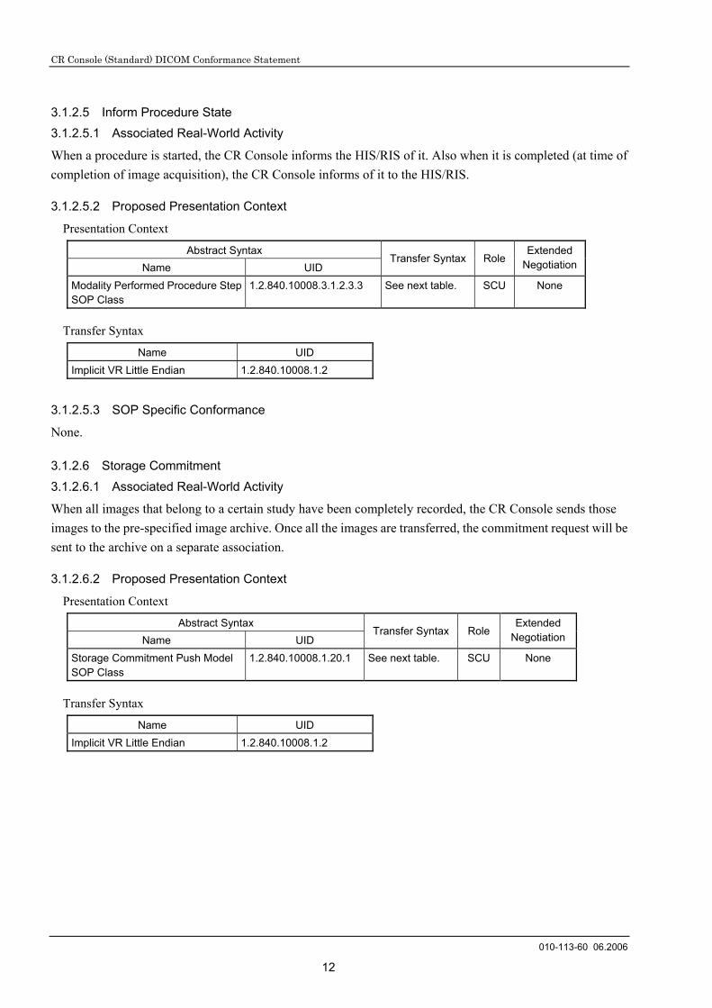
3.1.2.5 Inform Procedure State 3.1.2.5.1 Associated Real-World Activity
When a procedure is started, the CR Console informs the HIS/RIS of it. Also when it is completed (at time of completion of image acquisition), the CR Console informs of it to the HIS/RIS.
3.1.2.5.2 Proposed Presentation Context
Presentation Context
Abstract Syntax Name UID
Transfer Syntax Role Extended
Negotiation
Modality Performed Procedure Step SOP Class
1.2.840.10008.3.1.2.3.3 See next table. SCU None
Transfer Syntax
Name UID Implicit VR Little Endian 1.2.840.10008.1.2
3.1.2.5.3 SOP Specific Conformance
None.
3.1.2.6 Storage Commitment 3.1.2.6.1 Associated Real-World Activity
When all images that belong to a certain study have been completely recorded, the CR Console sends those images to the pre-specified image archive. Once all the images are transferred, the commitment request will be sent to the archive on a separate association.
3.1.2.6.2 Proposed Presentation Context
Presentation Context
Abstract Syntax Name UID
Transfer Syntax RoleExtended
Negotiation
Storage Commitment Push Model SOP Class
1.2.840.10008.1.20.1 See next table. SCU None
Transfer Syntax
Name UID Implicit VR Little Endian 1.2.840.10008.1.2
CR Console (Standard) DICOM Conformance Statement
010-113-60 06.2006
13
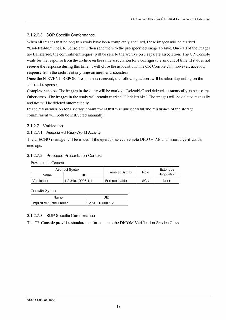
3.1.2.6.3 SOP Specific Conformance
When all images that belong to a study have been completely acquired, those images will be marked “Undeletable.” The CR Console will then send them to the pre-specified image archive. Once all of the images are transferred, the commitment request will be sent to the archive on a separate association. The CR Console waits for the response from the archive on the same association for a configurable amount of time. If it does not receive the response during this time, it will close the association. The CR Console can, however, accept a response from the archive at any time on another association. Once the N-EVENT-REPORT response is received, the following actions will be taken depending on the status of response. Complete success: The images in the study will be marked “Deletable” and deleted automatically as necessary. Other cases: The images in the study will remain marked “Undeletable.” The images will be deleted manually and not will be deleted automatically. Image retransmission for a storage commitment that was unsuccessful and reissuance of the storage commitment will both be instructed manually.
3.1.2.7 Verification 3.1.2.7.1 Associated Real-World Activity
The C-ECHO message will be issued if the operator selects remote DICOM AE and issues a verification message.
3.1.2.7.2 Proposed Presentation Context
Presentation Context
Abstract Syntax Name UID
Transfer Syntax Role Extended
Negotiation
Verification 1.2.840.10008.1.1 See next table. SCU None
Transfer Syntax
Name UID Implicit VR Little Endian 1.2.840.10008.1.2
3.1.2.7.3 SOP Specific Conformance
The CR Console provides standard conformance to the DICOM Verification Service Class.

CR Console (Standard) DICOM Conformance Statement
010-113-60 06.2006
14
3.1.3 Association Acceptance Policy
A single association will be accepted at any time to receive Storage Commitment responses. A single association will be accepted at any time to verify application level communication by using the C-EHO service.
3.1.3.1 Verification Request from Remote AE 3.1.3.1.1 Associated Real-World Activity
The CR Console is indefinitely listening for associations. No operator action is required to respond to a verification message.
3.1.3.1.2 Presentation Context
Presentation Context
Abstract Syntax Name UID
Transfer Syntax Role Extended
Negotiation
Verification 1.2.840.10008.1.1 See next table. SCP None
Transfer Syntax
Name UID Implicit VR Little Endian 1.2.840.10008.1.2
3.1.3.1.3 SOP Specific Conformance
The CR Console provides standard conformance to the DICOM Verification Service Class.

CR Console (Standard) DICOM Conformance Statement
010-113-90 06.2007
15
4. Communication Profiles
4.1 Supported Communication Stacks
DICOM Upper Layer is supported using TCP/IP.
4.2 TCP/IP Stack
The TCP/IP stack is inherited from the Windows 2000/XP Operating System.
4.3 Physical Media Support
IEEE 802.3 (10BASE-T) / IEEE 802.3U (100BASE-TX)
5. Standard Extended / Specialized / Privatization
The CR Console uses some private IOD modules.
The CR Console optionally allows Pixel Spacing (0028,0030) attribute to be used. If this field is used, the
actual size of any objects displayed on the workstation may not be accurate.
See “8. Information Object Definitions”.
6. Configuration
The CR Console can be configured on the DICOM characteristics specified below.
Local IP Address Host name AE Title Port number
Remote IP Address Host name AE Title Port number
7. Support of Extended Character Sets
ISO-IR 100 (Latin Alphabet #1) ISO-IR 101 (Latin Alphabet #2) ISO-IR 13/14 (Japanese Katakana: JIS X 0201) ISO-IR 87 (Japanese Kanji: JIS X 0208) ISO-IR 192 (Unicode: UTF-8) GB18030

CR Console (Standard) DICOM Conformance Statement
010-113-60 06.2006
16
8. CR IOD Overview
This section describes the CR IOD that the CR Console handles.
8.1 CR Image IOD Module Table Following is a list of the modules used for the CR image storage SOP class.
Information Entity Module Usage Method Reference Patient Patient M 8.2.1.1 Study General Study M 8.2.2.1 Patient Study U 8.2.2.2 Series General Series M 8.2.3.1 CR Series M 8.2.6.1 Equipment General Equipment M 8.2.4.1 Image General Image M 8.2.5.1 Image Pixels M 8.2.5.2 Contrast/Bolus C 8.2.5.3 CR Image M 8.2.6.2 Overlay U Not supported. Curve U Not supported. Modality LUT U 8.2.6.3 VOI LUT U 8.2.6.5 Common SOP M 8.2.7.1 DX Positioning U 9.2.5.4 X-ray Acquisition Dose U 9.2.4.1 X-ray Generation U 9.2.4.2 X-ray Grid U 9.2.4.3 Other Study Classification U 8.2.6.4
Private Control Information U 8.2.8.1 Private Exposure Information U 8.2.8.2 Private Print Information U 8.2.8.3 Private Image Information U 8.2.8.4
8.2 Information Module Definitions
Tags not specifically mentioned in notes are handled in the same way as DICOM definitions.
8.2.1 Patient IE Module
8.2.1.1 Patient Module
Attribute Name Tag Type DICOM Definition Implementation on
CR Console Patient’s Name (0010,0010) 2 Patient’s name Multi-byte base Patient ID (0010,0020) 2 Main hospital ID no. or code for patient Patient’s Birth Date (0010,0030) 2 Patient’s date of birth Patient’s Sex (0010,0040) 2 Patient’s sex. Enumerated values:
M = Male F = Female O = Other
If not set, Length = 0.

CR Console (Standard) DICOM Conformance Statement
010-113-60 06.2006
17
Other Patient IDs (0010,1000) 3 Other identification numbers or codes are used to identify the patient.
Ethnic Group (0010,2160) 3 Ethnic group or race of the patient. Patient Comments (0010,4000) 3 User-defined additional information
about the patient.
8.2.2 Study IE Module
8.2.2.1 General Study Module
Attribute Name Tag Type DICOM Definition Implementation on CR Console Study Instance UID (0020,000D) 1 Identifier unique to study An HIS/RIS-generated / IDT-generated /
IR-generated number is set. When not obtained from HIS/RIS, CR Console will generate this information by one of the following methods. 1. Generate by Accession Number. 2. Generate by Accession Number &
Study Date. 3. Generate by Study Date & Patient ID
& Modality. 4. Generate by Study Date & Patient ID
& Requesting Service. 5. Generate UID by each image.
Study Date (0008,0020) 2 Date study began. Date compilation of study information began
Study Time (0008,0030) 2 Time study began. Time compilation of study information began
Referring Physician’s Name
(0008,0090) 2 Physician making referral Due to the current lack of means of input, Length = 0 at the modality. Values received from another company’s modalities will be stored.
Study ID (0020,0010) 2 Study identifier issued by user or equipment
Information is set so that modalities can identify test types.
Accession Number (0008,0050) 2 HIS/RIS-issued number for identifying order of study.
An HIS/RIS-issued study number is set. When not obtained from HIS/RIS, Length = 0.
Study Description (0008,1030) 3 Institution-issued description or classification of study (component element) conducted
Physician(s) of Record
(0008,1048) 3 Physician(s) who are responsible for overall patient care at time of Study.
8.2.2.2 Patient Study Module
Attribute Name Tag Type DICOM Definition Implementation on CR Console Additional Patient’s History
(0010,21B0) 3 Additional information about the Patient's medical history.

CR Console (Standard) DICOM Conformance Statement
010-113-60 06.2006
18
8.2.3 Series IE Module
8.2.3.1 General Series Module
Attribute Name Tag Type DICOM Definition Implementation on
CR Console Modality (0008,0060) 1 Modality CR Operator’s Name (0008,1070) 3 Technologist supporting the Series Series Instance UID (0020,000E) 1 Identifier unique to series Generate UID by each image.Series Number (0020,0011) 2 Series ID number Laterality (0020,0060) 2 Whether right or left of body part is to be
examined. Necessary when part to be examined is pair-structured. Enumerated values:
R = Right L = Left
Length = 0
Series Date (0008,0021) 3 Date series began Series Time (0008,0031) 3 Time series began Series Description (0008,103E) 3 Description provided by series user Protocol Name (0018,1030) 3 User-defined description of the
conditions under which the Series was performed. Note: This attribute conveys series
specific protocol identification and may or may not be identical to the one presented in the Performed Protocol Code Sequence (0040,0260).
Protocol Name
Referenced Study Component Sequence
(0008,1111) 3 Uniquely identifies the Study Component SOP Instance or Modality Performed Procedure step SOP Instance to which the series is related.The Sequence shall have one item.
Referenced Study ComponentSequence
>Referenced SOP Class UID
(0008,1150) 1C Uniquely identifies the referenced SOP Class. Required if Referenced Study Component Sequence (0008,1111) is sent.
>Referenced SOP Class UID
>Referenced SOP Instance UID
(0008,1155) 1C Uniquely identifies the referenced SOP Instance. Required if Referenced Study Component Sequence (0008,1111) is sent.
>Referenced SOP Instance UID
Body Part Examined (0018,0015) 3 Description of test of body part to be examined. Definitions: SKULL, CSPINE, TSPINE, LSPINE, SSPINE, COCCYX, CHEST, CLAVICLE, BREAST, ABDOMEN, PELVIS, HIP, SHOULDER, ELBOW, KNEE, ANKLE, HAND, FOOT, EXTREMITY
Values shown below are used for CR. Body part definitions not existing in the DICOM definitions will be added. HEAD, NECK, CHEST, BREAST, ABDOMEN, PELVIS, UP_EXM, LOW_EXM, TEST
Performed Procedure Step ID
(0040,0253) 3 Identification of that part of a Procedure that has been carried out within this step.
CR Console (Standard) DICOM Conformance Statement
010-113-60 06.2006
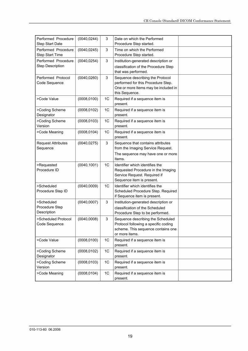
19
Performed Procedure Step Start Date
(0040,0244) 3 Date on which the Performed Procedure Step started.
Performed Procedure Step Start Time
(0040,0245) 3 Time on which the Performed Procedure Step started.
Performed Procedure Step Description
(0040,0254) 3 Institution-generated description or classification of the Procedure Step that was performed.
Performed Protocol Code Sequence
(0040,0260) 3 Sequence describing the Protocol performed for this Procedure Step. One or more Items may be included in this Sequence.
>Code Value (0008,0100) 1C Required if a sequence item is present.
>Coding Scheme Designator
(0008,0102) 1C Required if a sequence item is present.
>Coding Scheme Version
(0008,0103) 1C Required if a sequence item is present.
>Code Meaning (0008,0104) 1C Required if a sequence item is present.
Request Attributes Sequence
(0040,0275) 3 Sequence that contains attributes from the Imaging Service Request. The sequence may have one or more Items.
>Requested Procedure ID
(0040,1001) 1C Identifier which identifies the Requested Procedure in the Imaging Service Request. Required if Sequence item is present.
>Scheduled Procedure Step ID
(0040,0009) 1C Identifier which identifies the Scheduled Procedure Step. Required if Sequence item is present.
>Scheduled Procedure Step Description
(0040,0007) 3 Institution-generated description or classification of the Scheduled Procedure Step to be performed.
>Scheduled Protocol Code Sequence
(0040,0008) 3 Sequence describing the Scheduled Protocol following a specific coding scheme. This sequence contains one or more items.
>Code Value (0008,0100) 1C Required if a sequence item is present.
>Coding Scheme Designator
(0008,0102) 1C Required if a sequence item is present.
>Coding Scheme Version
(0008,0103) 1C Required if a sequence item is present.
>Code Meaning (0008,0104) 1C Required if a sequence item is present.
CR Console (Standard) DICOM Conformance Statement
010-113-80 03.2007
20
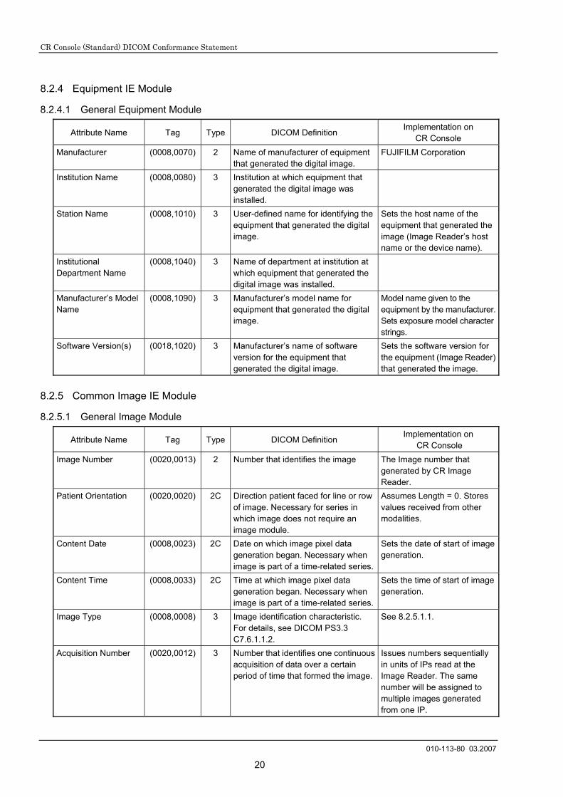
8.2.4 Equipment IE Module
8.2.4.1 General Equipment Module
Attribute Name Tag Type DICOM Definition Implementation on
CR Console Manufacturer (0008,0070) 2 Name of manufacturer of equipment
that generated the digital image. FUJIFILM Corporation
Institution Name (0008,0080) 3 Institution at which equipment that generated the digital image was installed.
Station Name (0008,1010) 3 User-defined name for identifying the equipment that generated the digital image.
Sets the host name of the equipment that generated the image (Image Reader’s host name or the device name).
Institutional Department Name
(0008,1040) 3 Name of department at institution at which equipment that generated the digital image was installed.
Manufacturer’s Model Name
(0008,1090) 3 Manufacturer’s model name for equipment that generated the digital image.
Model name given to the equipment by the manufacturer. Sets exposure model character strings.
Software Version(s) (0018,1020) 3 Manufacturer’s name of software version for the equipment that generated the digital image.
Sets the software version for the equipment (Image Reader) that generated the image.
8.2.5 Common Image IE Module
8.2.5.1 General Image Module
Attribute Name Tag Type DICOM Definition Implementation on
CR Console Image Number (0020,0013) 2 Number that identifies the image The Image number that
generated by CR Image Reader.
Patient Orientation (0020,0020) 2C Direction patient faced for line or row of image. Necessary for series in which image does not require an image module.
Assumes Length = 0. Stores values received from other modalities.
Content Date (0008,0023) 2C Date on which image pixel data generation began. Necessary when image is part of a time-related series.
Sets the date of start of image generation.
Content Time (0008,0033) 2C Time at which image pixel data generation began. Necessary when image is part of a time-related series.
Sets the time of start of image generation.
Image Type (0008,0008) 3 Image identification characteristic. For details, see DICOM PS3.3 C7.6.1.1.2.
See 8.2.5.1.1.
Acquisition Number (0020,0012) 3 Number that identifies one continuous acquisition of data over a certain period of time that formed the image.
Issues numbers sequentially in units of IPs read at the Image Reader. The same number will be assigned to multiple images generated from one IP.
CR Console (Standard) DICOM Conformance Statement
010-113-60 06.2006
21
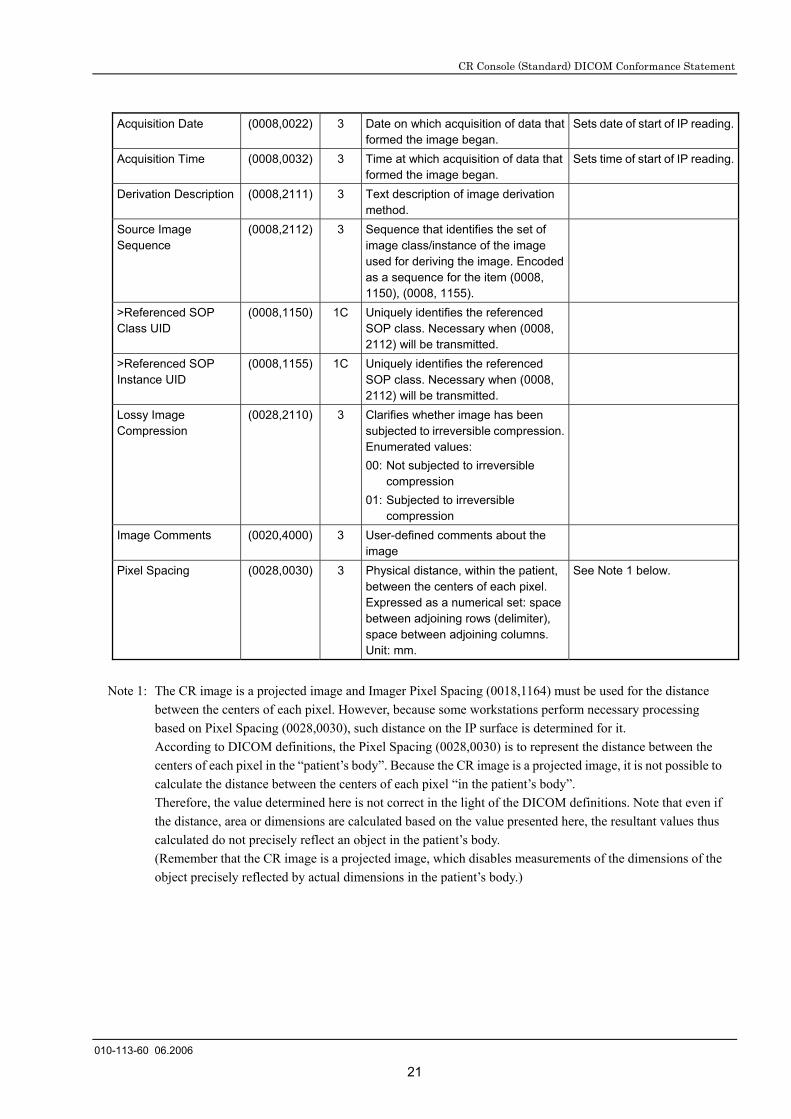
Acquisition Date (0008,0022) 3 Date on which acquisition of data that formed the image began.
Sets date of start of IP reading.
Acquisition Time (0008,0032) 3 Time at which acquisition of data that formed the image began.
Sets time of start of IP reading.
Derivation Description (0008,2111) 3 Text description of image derivation method.
Source Image Sequence
(0008,2112) 3 Sequence that identifies the set of image class/instance of the image used for deriving the image. Encoded as a sequence for the item (0008, 1150), (0008, 1155).
>Referenced SOP Class UID
(0008,1150) 1C Uniquely identifies the referenced SOP class. Necessary when (0008, 2112) will be transmitted.
>Referenced SOP Instance UID
(0008,1155) 1C Uniquely identifies the referenced SOP class. Necessary when (0008, 2112) will be transmitted.
Lossy Image Compression
(0028,2110) 3 Clarifies whether image has been subjected to irreversible compression. Enumerated values: 00: Not subjected to irreversible
compression 01: Subjected to irreversible
compression
Image Comments (0020,4000) 3 User-defined comments about the image
Pixel Spacing (0028,0030) 3 Physical distance, within the patient, between the centers of each pixel. Expressed as a numerical set: space between adjoining rows (delimiter), space between adjoining columns. Unit: mm.
See Note 1 below.
Note 1: The CR image is a projected image and Imager Pixel Spacing (0018,1164) must be used for the distance
between the centers of each pixel. However, because some workstations perform necessary processing based on Pixel Spacing (0028,0030), such distance on the IP surface is determined for it. According to DICOM definitions, the Pixel Spacing (0028,0030) is to represent the distance between the centers of each pixel in the “patient’s body”. Because the CR image is a projected image, it is not possible to calculate the distance between the centers of each pixel “in the patient’s body”. Therefore, the value determined here is not correct in the light of the DICOM definitions. Note that even if the distance, area or dimensions are calculated based on the value presented here, the resultant values thus calculated do not precisely reflect an object in the patient’s body. (Remember that the CR image is a projected image, which disables measurements of the dimensions of the object precisely reflected by actual dimensions in the patient’s body.)

CR Console (Standard) DICOM Conformance Statement
010-113-60 06.2006
22
8.2.5.1.1 Image Type
The Image Type consists of the following elements as per DICOM definitions.
Value 1: Pixel data Characteristics Value 2: Patient Examination Characteristics Value 3: Modality Specific Characteristics Value 4 or after: Other Value “n” (“n” represents a numeric value.)
On the FCR system, the above values should be interpreted as described below. Note that each of the elements may be omitted (only delimiters exist). When a portion after a certain element is fully omitted, even delimiters do not exist.
Because Value 1 and Value 2 have DICOM-defined meanings, they comply with the DICOM definitions. If omitted, they will be considered to be “ORIGINAL” or “PRIMARY”.
Value 3 determines image data types such as pre-normalized image, normalized image or processed image. If omitted, it will be considered to be “NORMALIZED”.
Value 4 (Other Value 1) represents processing purpose type of an image. When omitted, it will be considered to be “RT”.
Value 5 (Other Value 2) determines a types of change processing performed on an original image. Value 5 will not be determined if no changes have been made.
Value 6 (Other Value 3) determines a date of the change made on an image with Value 5 (Other Value 2) above. Value 6 will not be determined if no changes have been made.
Value 7 (Other Value 4) determines a type of special processing performed on an image, which will not be determined if no special image processing has been performed.
Value 8 (Other Value 5) determines a date of the special image processing performed with Value 7 (Other Value 4) above. Value 8 will not be determined if no special image processing has been performed.
Value 9 (Other Value 6) determines the distance (nm) between the centers of each pixel when an IP is read.
Each of the values mentioned above will represent the following specific meaning.
Value 1: (as per DICOM definitions)
ORIGINAL An image whose pixel size is based on the original image (pre-normalized image or normalized image).
DERIVED An image derived from pixel size of one or more images according to a specific method. (processed image).
Value 2: (as per DICOM definitions)
PRIMARY An image generated as a direct result from a patient study.
SECONDARY An image generated after the first patient study.

CR Console (Standard) DICOM Conformance Statement
010-113-60 06.2006
23
Value 3:
PRE_NORMALIZED A pre-normalized image.
NORMALIZED A normalized image.
POST_PROCESSED An already processed image.
Value 4:
RT Routine exposure image
ES_L Low-pressure image for energy subtraction processing.
ES_H High-pressure image for energy subtraction processing.
Value 5:
RENORMALIZED A re-normalized image.
MODIFIED_PARAM An image on which image processing parameters have been modified.
Value 6 and Value 8:
Determine in the “YYYYMMDDhhmmss” format a date when image processing was performed.
Value 7:
STICHED Image composition processing that generates one image from multiple images.
BONE A bone image based on the energy subtraction processing.
SOFT_TISSUE Soft tissue image based on the energy subtraction processing.
Value 9:
The distance (nm) between the centers of each pixel when an IP is read.
When “RENORMALIZED” has been determined for Value 5, what is determined will not be changed even if parameters were modified.

CR Console (Standard) DICOM Conformance Statement
010-113-60 06.2006
24
8.2.5.2 Image Pixel Module
Attribute Name Tag Type DICOM Definition Implementation on
CR Console Samples per Pixel (0028,0002) 1 Number of sample surfaces an image
has. Fixed at 1.
Photometric Interpretation
(0028,0004) 1 Specifies the intended interpretation of image data. MONOCHROME1 Indicates that pixel data has a single monochrome image surface. Minimum sample value is to be displayed in white following VOI gray scale conversion. MONOCHROME2 Indicates that pixel data has a single monochrome surface. Minimum sample value is to be displayed in black following VOI gray scale conversion. The following definitions also exist: PALETTE COLOR, RGB, HSV, ARCB, CMYK
Fixed at MONOCHROME1.
Rows (0028,0010) 1 Number of rows in an image
Columns (0028,0011) 1 Number of columns in an image
Bits Allocated (0028,0100) 1 Number of bits allocated to each pixel sample. Each sample has the same number of bits allocated.
Bit Stored (0028,0101) 1 Number of bits to be stored for each pixel sample. Each sample will have the same number of bits stored.
High Bit (0028,0102) 1 High bit for each pixel sample. Each sample will have the same number of high bits.
Pixel Representation (0028,0103) 1 Data representation for pixel sample. Each sample will have the same pixel representation. Enumerated values:
0000H: Integer with no encoding 0001H: Complement of 2.
0000H.
Pixel Data (7FE0,0010) 1 Stream of pixel samples that compose the image.
8.2.5.3 Contrast/Bolus Module
This is necessary when a contrast medium or bolus has been used (and is not necessary when they have not). As there is no means for determining whether they have been used, a tag will be attached but no information set.
Attribute Name Tag Type DICOM Definition Implementation on
CR Console Contrast/Bolus Agent (0018,0010) 2 Contrast or bolus agent Length = 0

CR Console (Standard) DICOM Conformance Statement
010-113-60 06.2006
25
8.2.6 Computed Radiography Image
8.2.6.1 CR Series Module
Attribute Name Tag Type DICOM Definition Implementation on
CR Console Body Part Examined (0018,0015) 2 Text description of body part
examined. Definitions follow. SKULL, CSPINE, TSPINE, LSPINE, SSPINE, COCCYX, CHEST, CLAVICLE, BREAST, ABDOMEN, PELVIS, HIP, SHOULDER, ELBOW, KNEE, ANKLE, HAND, FOOT, EXTREMITY
Values shown below are used for CR. Body part definitions not existing in the DICOM definitions will be added. HEAD, NECK, CHEST, BREAST, ABDOMEN, PELVIS, UP_EXM, LOW_EXM, TEST
View Position (0018,5101) 2 Visual field of X-ray related to patient’s position. Definitions follow.
AP = Anterior/Posterior PA = Posterior/Anterior LL = Left Lateral RL = Right Lateral RLD = Right Lateral Decubitus LLD = Left Lateral Decubit RLD = Right Lateral Oblique LLD = Left Lateral Oblique
Length = 0
8.2.6.2 CR Image Module
Attribute Name Tag Type DICOM Definition Implementation on CR Console
KVP (0018,0060) 3 Peak KVP output of the X-ray-generator used.
Plate ID (0018,1004) 3 ID or serial no. of the sensing plate on which the image was collected.
Sets the IP bar code no. Format: “a********c”
Exposure Time (0018,1150) 3 X-ray exposure time. Unit: msec.
X-ray Tube Current (0018,1151) 3 X-ray tube current. Unit: mA.
Exposure (0018,1152) 3 The exposure in mAs, for example calculated from Exposure Time and X-ray Tube Current.
Exposure in µAs (0018,1153) 3 The exposure expressed in µAs, for example calculated from Exposure Time and X-ray Tube Current.
Imager Pixel Spacing (0018,1164) 3 Physical distance measured at the front of the detector housing between the center of each image pixel specified by a numeric pair – row spacing value (delimiter) column spacing value in mm.
See Note 1 below.
Acquisition Device Processing Description
(0018,1400) 3 Processing descriptions particular to image-related equipment. (Ex.: description of internal organ.)
Sets menu name. Exposure menu name.

CR Console (Standard) DICOM Conformance Statement
010-113-90 06.2007
26
Acquisition Device Processing Code
(0018,1401) 3 Code indicating processing particular to image-related equipment. (Ex.: CR internal organ filter code.)
Sets menu code. Codifies the body part, exposure method and exposure menu. Taken to be FFFF if no value exists.
Sensitivity (0018,6000) 3 Reading sensitivity
Note 1: Note that the implementation differs depending on the used CR Console software version.
Software Ver. Implementation on CR Console All the A versions and V1.0 (B) to V1.2 (B) (HotFix and service pack for those versions are included.)
The distance between the centers of each pixel when an IP is read. Variations in the distance between the centers of each pixel, due to the change made in the pixel density after an IP has been read accordingly, will not be reflected. Therefore, it is not possible to calculate the distance between the two points using this data.
V2.0 (B) or later When the pixel density was subjected to change after an IP has been read, it was adjusted appropriately so that the influence of such a change is reflected accordingly. It will always be the distance between the centers of each pixel on the IP surface of the pixel data determined to be the PixelData (7FE0,0010).
8.2.6.3 Modality LUT Module
Attribute Name Tag Type DICOM Definition Implementation on
CR Console Rescale Intercept (0028,1052) 1C Output unit specified within Storage
Value (SV) and Rescale Type (0028,1054) is m *SV + b. Necessary when Modality LUT Sequence (0028,3000) does not exist.
0
Rescale Slope (0028,1053) 1C This is the “m” within the formula given in terms of Rescale Intercept (0028,1052). Necessary when Rescale Intercept exists.
1
Rescale Type (0028,1054) 1C Specifies the output values for Rescale Slope (0028,1053) and Rescale Intercept (0028,1052). Necessary when Rescale Intercept exists.
US
Modality LUT Sequence
(0028,3000) 1C Defines a sequence of Modality LUTs.
>LUT Descriptor (0028,3002) 1C Specifies the format of the LUT Datain this Sequence. See C.11.1.1 for further explanation.Required if the Modality LUT Sequence (0028,3000) is sent.
n2 \0\16 n :Bit Depth of image
>LUT Explanation (0028,3003) 3 Free form text explanation of the meaning of the LUT.
CRTLUT
>Modality LUT Type (0028,3004) 1C Specifies the output values of this Modality LUT. See C.11.1.1.2 for further explanation. Required if the Modality LUT Sequence (0028,3000) is sent.
US

CR Console (Standard) DICOM Conformance Statement
010-113-90 06.2007
27
>LUT Data (0028,3006) 1C LUT Data in this Sequence. Required if the Modality LUT Sequence (0028,3000) is sent.
8.2.6.4 Study Classification Module
Attribute Name Tag Type DICOM Definition Implementation on
CR Console Study Comments (0032,4000) 3 User-defined comments about the
study
8.2.6.5 VOI LUT Module
Attribute Name Tag Type DICOM Definition Implementation on
CR Console VOI LUT Sequence (0028,3010) 3 Defines a sequence of VOI LUTs. >LUT Descriptor (0028,3002) 1C Specifies the format of the LUT Data
in this Sequence. See PS3.3 C.11.2.1.1 for further explanation. Required if the VOI LUT Sequence (0028,3010) is sent.
>LUT Explanation (0028,3003) 3 Free from text explanation of the meaning of the LUT.
>LUT Data (0028,3006) 1C LUT Data in this Sequence. Required if the VOI LUT Sequence (0028,3010) is sent.
8.2.7 General Module
8.2.7.1 SOP Common Module
Attribute Name Tag Type DICOM Definition Implementation on
CR Console SOP Class UID (0008,0016) 1 Uniquely identifies the SOP class. SOP Instance UID (0008,0018) 1 Uniquely identifies the SOP instance.
Specific Character Set (0008,0005) 1C Used to expand the basic figure set or when using a substitute character set. Necessary in expansion or when using a substitute character set.
Alphanumerics: No tag European languages:
ISO_IR 100 \ ISO_IR 101 Japanese (backslash is half-size)
Half-size kana only: ISO_IR 13
Half-size kana + kanji: ISO 2022 IR 13 \ ISO 2022 IR 87
Unicode (UTF-8): ISO_IR 192
Chinese Simplified: GB18030
CR Console (Standard) DICOM Conformance Statement
010-113-90 06.2007
28
8.2.8 Private Module
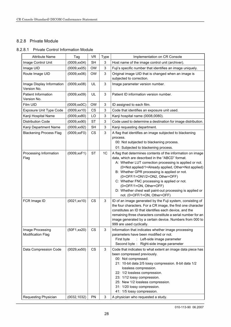
8.2.8.1 Private Control Information Module
Attribute Name Tag VR Type Implementation on CR Console Image Control Unit (0009,xx04) SH 3 Host name of the image control unit (archiver). Image UID (0009,xx05) OW 3 Fuji’s specific number that identifies an image uniquely. Route Image UID (0009,xx06) OW 3 Original image UID that is changed when an image is
subjected to correction. Image Display Information Version No.
(0009,xx08) UL 3 Image parameter version number.
Patient Information Version No.
(0009,xx09) UL 3 Patient ID information version number.
Film UID (0009,xx0C) OW 3 ID assigned to each film. Exposure Unit Type Code (0009,xx10) CS 3 Code that identifies an exposure unit used. Kanji Hospital Name (0009,xx80) LO 3 Kanji hospital name (0008,0080). Distribution Code (0009,xx90) ST 3 Code used to determine a destination for image distribution.Kanji Department Name (0009,xx92) SH 3 Kanji requesting department. Blackening Process Flag (0009,xxF0) CS 3 A flag that identifies an image subjected to blackening
process. 00: Not subjected to blackening process. 01: Subjected to blackening process.
Processing Information Flag
(0009,xxF1) ST 1C A flag that determines contents of the information on image data, which are described in the “ABCD” format.
A: Whether LUT correction processing is applied or not. (0=Not applied/1=Already applied, Other=Not applied)
B: Whether GPR processing is applied or not. (0=OFF/1=ON1/2=ON2, Other=OFF)
C: Whether FNC processing is applied or not. (0=OFF/1=ON, Other=OFF)
D: Whether chest wall paint-out processing is applied or not. (0=OFF/1=ON, Other=OFF)
FCR Image ID (0021,xx10) CS 3 ID of an image generated by the Fuji system, consisting of the four characters. For a CR image, the first one character constitutes an ID that identifies each device, and the remaining three characters constitute a serial number for an image generated by a certain device. Numbers from 000 to 999 are used cyclically.
Image Processing Modification Flag
(50F1,xx20) CS 3 Information that indicates whether image processing parameters have been modified or not.
First byte : Left-side image parameter Second byte : Right-side image parameter
Data Compression Code (0029,xx50) CS 3 Code that indicates to what extent an image data piece has been compressed previously.
00: Not compressed. 21: 10-bit data 2/5 lossy compression. 8-bit data 1/2
lossless compression. 22: 1/2 lossless compression. 23: 1/12 lossy compression. 25: New 1/2 lossless compression. 31: 1/20 lossy compression. 41: 1/5 lossy compression.
Requesting Physician (0032,1032) PN 3 A physician who requested a study.
CR Console (Standard) DICOM Conformance Statement
010-113-90 06.2007
29
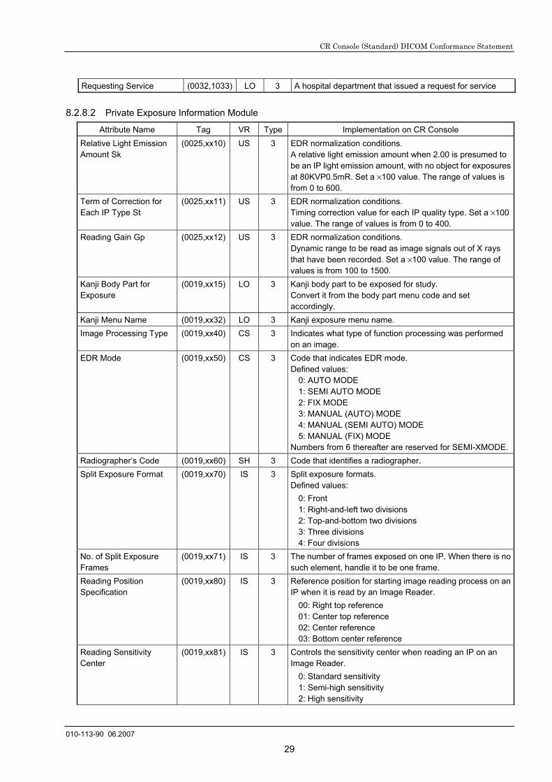
Requesting Service (0032,1033) LO 3 A hospital department that issued a request for service
8.2.8.2 Private Exposure Information Module
Attribute Name Tag VR Type Implementation on CR Console Relative Light Emission Amount Sk
(0025,xx10) US 3 EDR normalization conditions. A relative light emission amount when 2.00 is presumed to be an IP light emission amount, with no object for exposures at 80KVP0.5mR. Set a ×100 value. The range of values is from 0 to 600.
Term of Correction for Each IP Type St
(0025,xx11) US 3 EDR normalization conditions. Timing correction value for each IP quality type. Set a ×100 value. The range of values is from 0 to 400.
Reading Gain Gp (0025,xx12) US 3 EDR normalization conditions. Dynamic range to be read as image signals out of X rays that have been recorded. Set a ×100 value. The range of values is from 100 to 1500.
Kanji Body Part for Exposure
(0019,xx15) LO 3 Kanji body part to be exposed for study. Convert it from the body part menu code and set accordingly.
Kanji Menu Name (0019,xx32) LO 3 Kanji exposure menu name. Image Processing Type (0019,xx40) CS 3 Indicates what type of function processing was performed
on an image. EDR Mode (0019,xx50) CS 3 Code that indicates EDR mode.
Defined values: 0: AUTO MODE 1: SEMI AUTO MODE 2: FIX MODE 3: MANUAL (AUTO) MODE 4: MANUAL (SEMI AUTO) MODE 5: MANUAL (FIX) MODE
Numbers from 6 thereafter are reserved for SEMI-XMODE.Radiographer’s Code (0019,xx60) SH 3 Code that identifies a radiographer. Split Exposure Format (0019,xx70) IS 3 Split exposure formats.
Defined values: 0: Front 1: Right-and-left two divisions 2: Top-and-bottom two divisions 3: Three divisions 4: Four divisions
No. of Split Exposure Frames
(0019,xx71) IS 3 The number of frames exposed on one IP. When there is no such element, handle it to be one frame.
Reading Position Specification
(0019,xx80) IS 3 Reference position for starting image reading process on an IP when it is read by an Image Reader.
00: Right top reference 01: Center top reference 02: Center reference 03: Bottom center reference
Reading Sensitivity Center
(0019,xx81) IS 3 Controls the sensitivity center when reading an IP on an Image Reader.
0: Standard sensitivity 1: Semi-high sensitivity 2: High sensitivity

CR Console (Standard) DICOM Conformance Statement
010-113-90 06.2007
30
Set No. (0021,xx30) CS 3 A number that identifies function processing in the FCR system. Note, however, that the available range is from “1” to “ZZ”.
Image No. in the Set (0021,xx40) IS 3 Serial numbers from “01” to “99” within the set number (0021, xx30).
Pair Processing Information
(0021,xx50) CS 3 Information available when an operation is performed between images.
Equipment Type-Specific Information
(0021,xx80) OB 3 Image generator-specific information.
Energy Subtraction Param.
(50F1,xx06) CS 3 The four coefficient table types, Ta, Tb, Tc and Td, used for energy subtraction processing. Each parameter is represented by one character from A to T. Characters other than A to T are illegal. Note that each parameter is represented by one byte, four bytes in totality.
Subtraction Registration Result
(50F1,xx07) CS 3 Indicates the result of image positioning by energy subtraction processing.
0: OK 1: NG
Energy Subtraction Param. 2
(50F1,xx08) CS 1C Parameters to be used by new energy subtraction processing. These parameters are indispensable for images generated by new energy subtraction processing and for original images that will be subjected to new energy subtraction processing. For the former, the images imply to have been subjected to processing using these parameters, and for the latter, the images imply that they are to be subjected to processing using these parameters.
Afin Conversion Coefficient
(50F1,xx09) SL 1C The parameter that controls the afin conversion coefficient information for the purpose of image positioning during new energy subtraction processing. This parameter is stored to be VM=4 and is indispensable for images generated by new energy subtraction processing and for original images that will be subjected to new energy subtraction processing. For the former, the images imply to have been subjected to processing using this parameter, and for the latter, the images imply that they are to be subjected to processing using this parameter.
FNC Parameters (50F1,xx0A) SH 1C FNC parameters to be determined as character strings in order of FNL (A to Z), FRB (A to Z), FRT (A to Z) and FRE (0.0 to 1.0). Example: ABC0.7 When FNC is applied (when FNC is ON according to the processing information flag), this tag will be required. When FNC is OFF, this tag will not be output.
8.2.8.3 Private Print Information Module
Attribute Name Tag VR Type Implementation on CR Console Film Annotation Character String 1
(0019,xx90) SH 3 Film annotation character string 1.
Film Annotation Character String 2
(0019,xx91) SH 3 Film annotation character string 2.
Image Display Format (2010,0010) ST 3 Image display format type. A format based on which an image is output on film can be stored only when the four-frame format is used.

CR Console (Standard) DICOM Conformance Statement
010-113-90 06.2007
31
Annotation Display Format ID
(2010,0030) CS 3 Identifies an annotation display format, which is described as follows. “CR”+A+B “CR”: A character string that identifies a modality. A: Date of birth
0: Date of birth 1: Age
B: Film annotation character format (for identification of frontal/lateral) 0: Other than frontal/lateral 1: Frontal/lateral
Film Orientation (2010,0040) CS 3 Film orientation. Enumerated values are as follows. PORTRAIT and LANDSCAPE
Border Density (2010,0100) CS 3 The density between an image and its surroundings on film.Shown below are the densities defined by DICOM.
BLACK WHITE
Trim (2010,0140) CS 3 Specifies whether to print images with trimming frame or not. Enumerated values: YES or NO.
Image Position Specifying Flag
(2011,xx11) CS 3 Specifies an image display position within an area assigned for an image. The default value determined for each device prevails when no such information is set up.
00: Default position 01: Right-justified position 02: Left-justified position
Image Position (2020,0010) US 3 Image position on film according to a specified image display format.
Film Output Format (50F1,xx10) CS 3 Pre-set parameters used for CR image output format and image processing. Either “A” or “B” format is available. A 0: For previous models. Single for the 8”´10” format.
LR for others. 1: Single 2: L/R B 0: Parameters for the left-side image are used. 1: Parameters for ht right-side image are used. Other : Parameters for the left-side image are used.
8.2.8.4 Private Image Information Module
Attribute Name Tag VR Type Implementation on CR Console Image Scanning Direction
(0029,xx20) CS 3 Information that indicates a position where image data starts and to which direction the image data is scanned, assuming to be a reference a scanning direction where an image is scanned from top right to the left, when an exposed image is seen as a non-reverse image. This four-byte information has the following formats. First byte : 180° image rotation Second byte : Right-and-left image reversal in the main
scanning direction Third byte : 90° image rotation Fourth byte : Space
Extended Reading Size Value
(0029,xx30) CS 3 Image reading size.
CR Console (Standard) DICOM Conformance Statement
010-113-90 06.2007
32
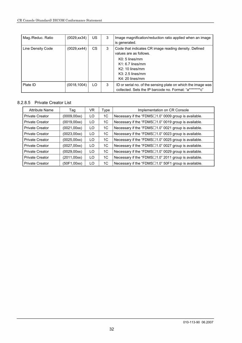
Mag./Reduc. Ratio (0029,xx34) US 3 Image magnification/reduction ratio applied when an image is generated.
Line Density Code (0029,xx44) CS 3 Code that indicates CR image reading density. Defined values are as follows.
K0: 5 lines/mm K1: 6.7 lines/mm K2: 10 lines/mm K3: 2.5 lines/mm K4: 20 lines/mm
Plate ID (0018,1004) LO 3 ID or serial no. of the sensing plate on which the image was collected. Sets the IP barcode no. Format: “a********c”
8.2.8.5 Private Creator List
Attribute Name Tag VR Type Implementation on CR Console Private Creator (0009,00xx) LO 1C Necessary if the “FDMS 1.0” 0009 group is available. Private Creator (0019,00xx) LO 1C Necessary if the “FDMS 1.0” 0019 group is available. Private Creator (0021,00xx) LO 1C Necessary if the “FDMS 1.0” 0021 group is available. Private Creator (0023,00xx) LO 1C Necessary if the “FDMS 1.0” 0023 group is available. Private Creator (0025,00xx) LO 1C Necessary if the “FDMS 1.0” 0025 group is available. Private Creator (0027,00xx) LO 1C Necessary if the “FDMS 1.0” 0027 group is available. Private Creator (0029,00xx) LO 1C Necessary if the “FDMS 1.0” 0029 group is available. Private Creator (2011,00xx) LO 1C Necessary if the “FDMS 1.0” 2011 group is available. Private Creator (50F1,00xx) LO 1C Necessary if the “FDMS 1.0” 50F1 group is available.
CR Console (Standard) DICOM Conformance Statement
010-113-60 06.2006
33
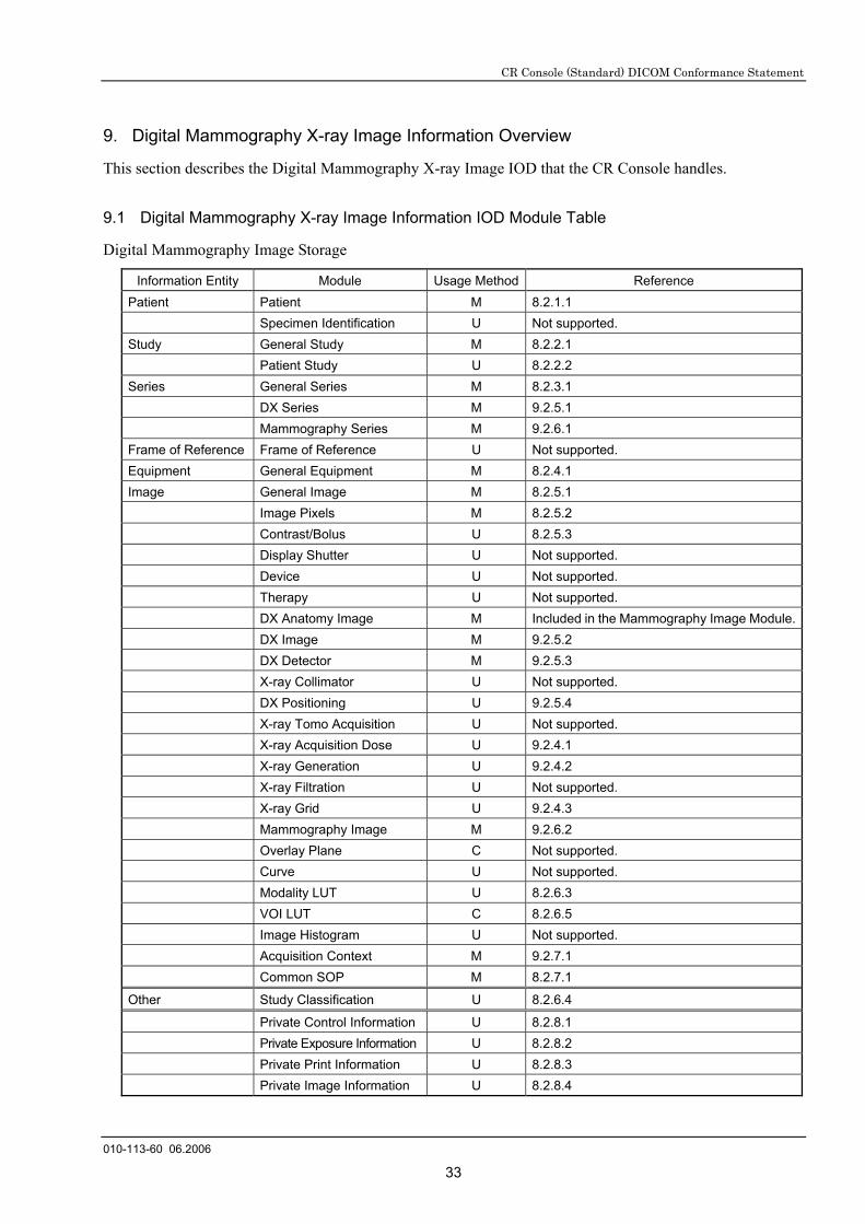
9. Digital Mammography X-ray Image Information Overview
This section describes the Digital Mammography X-ray Image IOD that the CR Console handles.
9.1 Digital Mammography X-ray Image Information IOD Module Table
Digital Mammography Image Storage
Information Entity Module Usage Method Reference Patient Patient M 8.2.1.1 Specimen Identification U Not supported. Study General Study M 8.2.2.1 Patient Study U 8.2.2.2 Series General Series M 8.2.3.1 DX Series M 9.2.5.1 Mammography Series M 9.2.6.1 Frame of Reference Frame of Reference U Not supported. Equipment General Equipment M 8.2.4.1 Image General Image M 8.2.5.1 Image Pixels M 8.2.5.2 Contrast/Bolus U 8.2.5.3 Display Shutter U Not supported. Device U Not supported. Therapy U Not supported. DX Anatomy Image M Included in the Mammography Image Module. DX Image M 9.2.5.2 DX Detector M 9.2.5.3 X-ray Collimator U Not supported. DX Positioning U 9.2.5.4 X-ray Tomo Acquisition U Not supported. X-ray Acquisition Dose U 9.2.4.1 X-ray Generation U 9.2.4.2 X-ray Filtration U Not supported. X-ray Grid U 9.2.4.3 Mammography Image M 9.2.6.2 Overlay Plane C Not supported. Curve U Not supported. Modality LUT U 8.2.6.3 VOI LUT C 8.2.6.5 Image Histogram U Not supported. Acquisition Context M 9.2.7.1 Common SOP M 8.2.7.1
Other Study Classification U 8.2.6.4
Private Control Information U 8.2.8.1 Private Exposure Information U 8.2.8.2 Private Print Information U 8.2.8.3 Private Image Information U 8.2.8.4

CR Console (Standard) DICOM Conformance Statement
010-113-60 06.2006
34
9.2 Information Module Definitions
Tags not specifically mentioned in notes are handled the same as DICOM definitions.
9.2.1 Series IE Module
9.2.1.1 General Series Module
See 8.2.3.1.
9.2.2 Equipment IE Module
9.2.2.1 General Equipment Module
See 8.2.4.1.
9.2.3 Common Image IE Module See 8.2.5.
9.2.4 X-ray Module
9.2.4.1 X-ray Acquisition Dose Module
Attribute Name Tag Type DICOM Definition Implementation on
CR Console KVP (0018,0060) 3 Peak kilo voltage output of the X-ray generated
used.
Distance Source to Detector
(0018,1110) 3 Distance in mm from source to detector center. Note: This value is traditionally referred to as
Source Image Distance (SID).
X-ray Tube Current (0018,1151) 3 X-ray Tube Current in mA
Exposure Time (0018,1150) 3 X-ray Tube Current in µA
Exposure (0018,1152) 3 The exposure in mAs, for example calculated from Exposure Time and X-ray Tube Current.
Exposure in µAs (0018,1153) 3 The exposure expressed in µAs, for example calculated from Exposure Time and X-ray Tube Current.
Image Area Dose Product
(0018,115E) 3 X-ray dose, measured in dGy*cm*cm, to which the patient was exposed for the acquisition of this image plus any nondigitally recorded fluoroscopy which may have been performed to prepare for the acquisition of this image. Notes: 1. The sum of the Image Area Dose
Product of all images of a Series or a Study may not result in the actual area dose product to which the patient was exposed.
2. This may be an estimated value based on assumptions about the patient’s body size and habitus.
CR Console (Standard) DICOM Conformance Statement
010-113-60 06.2006
35
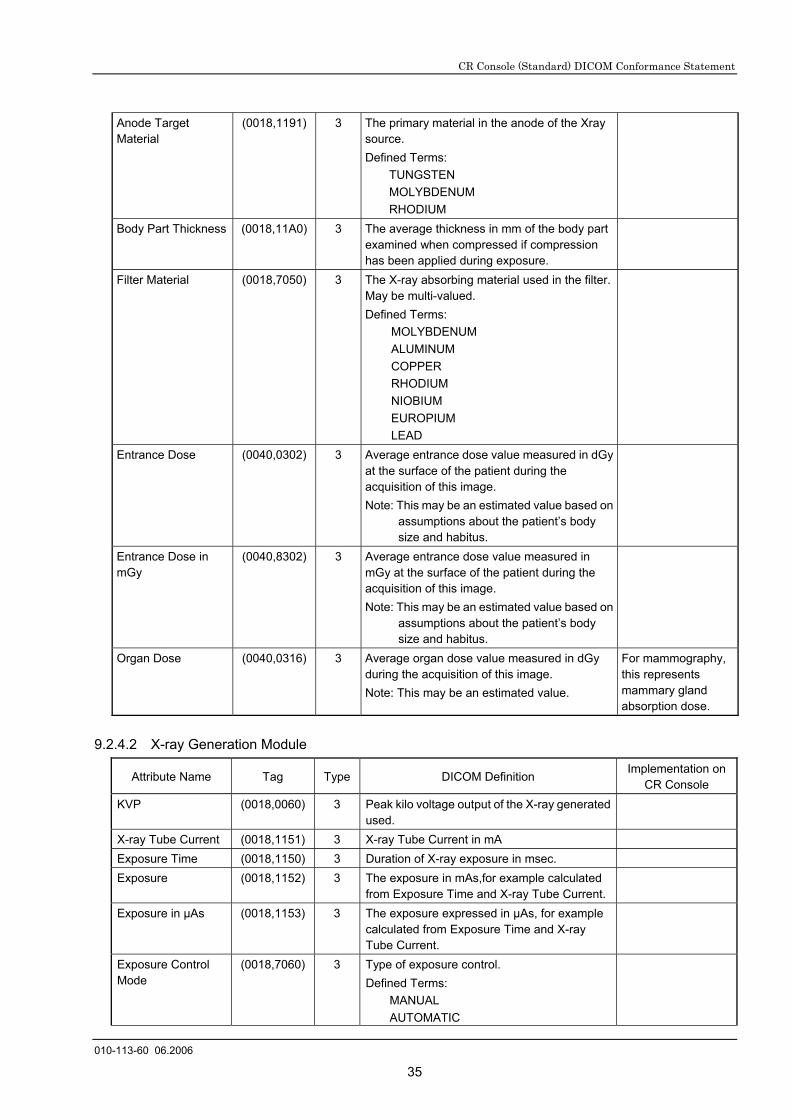
Anode Target Material
(0018,1191) 3 The primary material in the anode of the Xray source. Defined Terms:
TUNGSTEN MOLYBDENUM RHODIUM
Body Part Thickness (0018,11A0) 3 The average thickness in mm of the body part examined when compressed if compression has been applied during exposure.
Filter Material (0018,7050) 3 The X-ray absorbing material used in the filter. May be multi-valued. Defined Terms:
MOLYBDENUM ALUMINUM COPPER RHODIUM NIOBIUM EUROPIUM LEAD
Entrance Dose (0040,0302) 3 Average entrance dose value measured in dGy at the surface of the patient during the acquisition of this image. Note: This may be an estimated value based on
assumptions about the patient’s body size and habitus.
Entrance Dose in mGy
(0040,8302) 3 Average entrance dose value measured in mGy at the surface of the patient during the acquisition of this image. Note: This may be an estimated value based on
assumptions about the patient’s body size and habitus.
Organ Dose (0040,0316) 3 Average organ dose value measured in dGy during the acquisition of this image. Note: This may be an estimated value.
For mammography, this represents mammary gland absorption dose.
9.2.4.2 X-ray Generation Module
Attribute Name Tag Type DICOM Definition Implementation on
CR Console KVP (0018,0060) 3 Peak kilo voltage output of the X-ray generated
used.
X-ray Tube Current (0018,1151) 3 X-ray Tube Current in mA
Exposure Time (0018,1150) 3 Duration of X-ray exposure in msec.
Exposure (0018,1152) 3 The exposure in mAs,for example calculated from Exposure Time and X-ray Tube Current.
Exposure in µAs (0018,1153) 3 The exposure expressed in µAs, for example calculated from Exposure Time and X-ray Tube Current.
Exposure Control Mode
(0018,7060) 3 Type of exposure control. Defined Terms:
MANUAL AUTOMATIC

CR Console (Standard) DICOM Conformance Statement
010-113-60 06.2006
36
Exposure Control Mode Description
(0018,7062) 3 Text description of the mechanism of exposure control. May describe the number and type of exposure sensors or position of the sensitive area of the imaging detector.
Anode Target Material
(0018,1191) 3 The primary material in the anode of the Xray source. Defined Terms:
TUNGSTEN MOLYBDENUM RHODIUM
9.2.4.3 X-ray Grid Module
Attribute Name Tag Type DICOM Definition Implementation on
CR Console Grid (0018,1166) 3 Identifies the grid. May be multi-valued.
Defined Terms are: FIXED FOCUSED RECIPROCATING PARALLEL CROSSED NONE
Sets whether the grid is used or not. USED:
Grid is used. NONE:
Grid is not used.
9.2.5 DX Module
9.2.5.1 DX Series Module
Attribute Name Tag Type DICOM Definition Implementation on
CR Console Modality (0008,0060) 1 Type of equipment that originally acquired
the data used to create the image in this series. Enumerated Values: DX,PX,IO,MG
MG
Referenced Study Component Sequence
(0008,1111) 1C Uniquely identifies the Study Component SOP Instance or Modality Performed Procedure step SOP Instance to which the series is related. The Sequence shall have one item. Required if Study Component SOP Class or Modality Performed Procedure Step SOP Class is supported.
>Referenced SOP Class UID
(0008,1150) 1C Uniquely identifies the referenced SOP Class. Required if Referenced Study Component Sequence (0008,1111) is sent.
>Referenced SOP Instance UID
(0008,1155) 1C Uniquely identifies the referenced SOP Instance. Required if Referenced Study Component Sequence (0008,1111) is sent.

CR Console (Standard) DICOM Conformance Statement
010-113-60 06.2006
37
Presentation Intent Type
(0008,0068) 1 Identifies the intent of the images that are contained within this Series. Enumerated Values: FOR PRESENTATION FOR PROCESSING
FOR PRESENTATION or FOR PROCESSING
9.2.5.2 DX Image Module
Attribute Name Tag Type DICOM Definition Implementation on
CR Console Image Type (0008,0008) 1 Image identification characteristics.
See DICOM PS3-3 C.8.11.3.1.1 for specialization.
See 9.2.5.2.1.
Samples per Pixel (0028,0002) 1 Number of samples in this image. Shall have an Enumerated Value of 1.
1
Photometric Interpretation
(0028,0004) 1 Specifies the intended interpretation of the pixel data. Enumerated Values: MONOCHROME1 MONOCHROME2
MONOCHROME1
Bits Allocated (0028,0100) 1 Number of bits allocated for each pixel sample. Enumalated Values: 8, 16
Bits Stored (0028,0101) 1 Number of bits stored for each pixel sample. Enumerated Values: 6 to 16
High Bit (0028,0102) 1 Most significant bit for pixel sample data. Shall have an Enumerated value of one less than the value in Bits Stored (0028,0101).
Pixel Presentation (0028,0103) 1 Data representation of the pixel samples. Shall have an Enumerated value:
0000H = Unsigned Integer
0000H
Pixel Intensity Relationship
(0028,1040) 1 LOG
Pixel Intensity Relationship Sign
(0028,1041) 1 The sign of the relationship between the Pixel sample values stored in Pixel Data (7FE0,0010) and the X-ray beam intensity. Enumerated Values:
1 = Lower pixel values correspond to less X-ray beam intensity
-1 = Higher pixel values correspond to less X-ray beam intensity.
See DICOM PS3.3 C.8.11.3.1.2 for further explanation.
-1
Rescale Intercept (0028,1052) 1 The value b in the relationship between stored values (SV) in Pixel Data (7FE0,0010) and the output units specified in Rescale Type (0028,1054). Output units = m*SV + b. Enumerated Value: 0 See DICOM PS3.3 C.8.11.3.1.2 for further explanation.
0
CR Console (Standard) DICOM Conformance Statement
010-113-60 06.2006
38
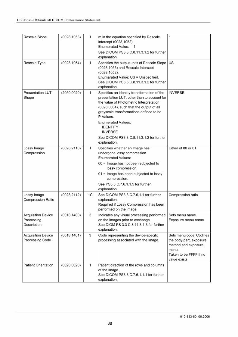
Rescale Slope (0028,1053) 1 m in the equation specified by Rescale intercept (0028,1052). Enumerated Value: 1 See DICOM PS3.3 C.8.11.3.1.2 for further explanation.
1
Rescale Type (0028,1054) 1 Specifies the output units of Rescale Slope (0028,1053) and Rescale Intercept (0028,1052). Enumarated Value: US = Unspecified. See DICOM PS3.3 C.8.11.3.1.2 for further explanation.
US
Presentation LUT Shape
(2050,0020) 1 Specifies an identity transformation of the presentation LUT, other than to account for the value of Photometric Interpretation (0028,0004), such that the output of all grayscale transformations defined to be P-Values. Enumerated Values:
IDENTITY INVERSE
See DICOM PS3.3 C.8.11.3.1.2 for further explanation.
INVERSE
Lossy Image Compression
(0028,2110) 1 Specifies whether an Image has undergone lossy compression. Enumerated Values: 00 = Image has not been subjected to
lossy compression. 01 = Image has been subjected to lossy
compression. See PS3.3 C.7.6.1.1.5 for further explanation.
Either of 00 or 01.
Lossy Image Compression Ratio
(0028,2112) 1C See DICOM PS3.3 C.7.6.1.1 for further explanation. Required if Lossy Compression has been performed on the image.
Compression ratio
Acquisition Device Processing Description
(0018,1400) 3 Indicates any visual processing performed on the images prior to exchange. See DIOM PS 3.3 C.8.11.3.1.3 for further explanation.
Sets menu name. Exposure menu name.
Acquisition Device Processing Code
(0018,1401) 3 Code representing the device-specific processing associated with the image.
Sets menu code. Codifies the body part, exposure method and exposure menu. Taken to be FFFF if no value exists.
Patient Orientation (0020,0020) 1 Patient direction of the rows and columns of the image. See DICOM PS3.3 C.7.6.1.1.1 for further explanation.

CR Console (Standard) DICOM Conformance Statement
010-113-60 06.2006
39
Burned In Annotation (0028,0301) 1 Indicates whether or not image contains sufficient burned in annotation to identify the patient and date the images acquired. Enumerated Values: YES NO
NO
Window Center (0028,1050) 1C Defines a Window Center for display. See DICOM PS3.3 C.8.11.3.1.5 for further explanation. Required if Presentation Intent Type (0008,0068) is FOR PRESENTATION and VOI LUT Sequence (0028,3010) is not present. May be present if VOI LUT Sequence (0028,3010) is present.
This tag type is 1C, but CR Console keeps this attribute with any condition.
Window Width (0028,1051) 1C Window Width for display. See DICOM PS3.3 C.8.11.3.1.5 for further explanation. Required if Window Center (0028,1050) is sent.
This tag type is 1C, but CR Console keeps this attribute with any condition.
VOI LUT Sequence (0028,3010) 3 Defines a sequence of VOI LUTs. >LUT Descriptor (0028,3002) 1C Specifies the format of the LUT Data in this
Sequence. See PS3.3 C.11.2.1.1 for further explanation. Required if the VOI LUT Sequence (0028,3010) is sent.
>LUT Explanation (0028,3003) 3 Free from text explanation of the meaning of the LUT.
>LUT Data (0028,3006) 1C LUT Data in this Sequence. Required if the VOI LUT Sequence (0028,3010) is sent.
9.2.5.2.1 Image Type
See 8.2.5.1.1. Note however that Value 1 and Value 3 are as follows.
Value 1:
ORIGINAL Normalized image (an exposed image that has been subjected to image processing, such as gradation processing.)
DERIVED An image created through morphological processing (long-view image, energy subtraction image).
Value 3:
Not determined.

CR Console (Standard) DICOM Conformance Statement
010-113-60 06.2006
40
9.2.5.3 DX Detector Module
Attribute Name Tag Type DICOM Definition Implementation on
CR Console Detector Type (0018,7004) 2 The Type of detector used to acquire this
image. Defined Terms; DIRECT = X-ray photoconductor SCINTILATOR = Phosphor used STORAGE = Storage Phosphor FILM = Scanned film/Screen
STORAGE
Detector Configuration
(0018,7005) 3 The physical configuration of the detector.Defined Terms; AREA = single or tiled detector SLOT = scanned slot, slit or spot
SLOT
Sensitivity (0018,6000) 3 Detector sensitivity in manufacturer specific units.
Reading sensitivity
Field of View Shape (0018,1147) 3 Shape of the Field of View, that is the image pixels stored in Pixels Data(7FE0,0010). Enumerated Value;
RECTANGLE ROUND HEXALGONAL
RECTANGLE
Field of View Dimension
(0018,1149) 3 Dimensions in mm of the Field of View , that is the image pixels stored in Pixel Data (7FE,0010). If Field of View Shape (0018,1147) is ; RECTANGLE: row dimension followed by
column. ROUND: diameter HEXAGONAL: diameter of a
circumscribed circle.
Sets image size.
Imager Pixel Spacing
(0018,1164) 1 Physical distance measured at the front place of the detector housing between the center of each image pixel specified by a numeric pair – row spacing value (delimiter) column spacing value in mm.
Same as for Imager Pixel Spacing (0018,1164) defined in 8.2.6.2 CR Image Module.

CR Console (Standard) DICOM Conformance Statement
010-113-60 06.2006
41
9.2.5.4 DX Positioning Module
Attribute Name Tag Type DICOM Definition Implementation on
CR Console Estimated Radiographic Magnification Factor
(0018,1114) 3 Ratio of Source Image Distance (SID) over Source Object Distance (SOD).
Set a 1/100 SID/SOD value.
Positioner Type (0018,1508) 2 Defined Terms: CARM
COLUMN MAMMOGRAPHIC PANORAMIC CEPHALOSTAT RIGID NONE
Notes: 1. The term CARM can apply to any positioner with 2 degrees of freedom of rotation of the X-ray beam about the Imaging Subject.
2. The term COLUMN can apply to any positioner with 1 degree of freedom of rotation of the X-ray beam about the Imaging Subject.
When CR or DX is used for Modality (0008,0060) and the following value is determined for mammography. MAMMOGRAPHIC NONE
When MG is used for Modality (0008,0060), determine the following value. MAMMOGRAPHIC
Positioner Primary Angle
(0018,1510) 3 Position of the X-ray beam about the patient from the RAO to LAO direction where movement from RAO to vertical is positive, if Positioner Type (0018,1508) is CARM.
Body Part Thickness (0018,11A0) 3 The average thickness in mm of the body part examined when compressed if compression has been applied during exposure.
Compression Force (0018,11A2) 3 The compression force applied to the body part during exposure, measured in Newtons.
9.2.6 Mammography Module
9.2.6.1 Mammography Series Module
Attribute Name Tag Type DICOM Definition Implementation on
CR Console Modality (0008,0060) 1 Type of equipment that originally acquired
the data used to create the image in this series. Enumerated Values:
MG
MG

CR Console (Standard) DICOM Conformance Statement
010-113-60 06.2006
42
9.2.6.2 Mammography Image Module
Attribute Name Tag Type DICOM Definition Implementation on
CR Console Positioner Type (0018,1508) 1 Enumerated Values:
MAMMOGRAPHIC NONE
When MG is used for Modality (0008,0060), determine the following value. MAMMOGRAPHIC
Positioner Primary Angle
(0018,1510) 3 Position in degrees of th X-ray beam in the coronal anatomical plane as if the patient were standing where movement of te X-ray source from anterior to posterior, is positive and vertical is zero.
Positioner Secondary Angle
(0018,1511) 3 Position in degrees of the X-ray beam in the sagittal anatomical plane as if the patient were standing where movement of the X-ray source from anterior to posterior, is positive, and certical is zero.
Image Laterality (0020,0062) 1 Laterality of the region examined. Enumerated Values:
R = right L = left B = both
Organ Exposed (0040,0318) 1 Organ to which Organ Dose (0040,0316) applies. Enumarated Value:
BREAST
BREAST
Anatomic Region Sequence
(0008,2218) 1 Sequence that describes the projection of the anatomic region of interest in this image. Only a single item shall be permitted in this sequence.
>Code Value (0008,0100) 1C T-04000 >Coding Scheme Designator
(0008,0102) 1C SNM3
>Code Meaning (0008,0104) 1C BREAST View Code Sequence
(0054,0220) 1 Sequence that describes the projection of the anatomic region of interest on the image receptor. Only a single item shall be permitted in this sequence.
>Include Code Sequence Macro >View Modifier Code Sequence
(0054,0222) 2 View modifier. Zero and more Items may be included in this Sequence.
Length = 0

CR Console (Standard) DICOM Conformance Statement
010-113-60 06.2006
43
9.2.6.2.1 View Code Sequence
Attribute Name Tag Type DICOM Definition Implementation on
CR Console >Code Value (0008,0100) 1C * >Code Scheme Designator
(0008,0102) 1C SNM3
>Code Meaning (0008,0104) 1C *
* Select one item from the table below to set.
Code Value (0008,0100) Code Meaning (0008,0104) ACR BI-RADS Equivalent R-10224 medio-lateral ML R-10226 medio-lateral oblique MLO R-10228 latero-medial LM R-10230 latero-medial oblique LMO R-10242 cranio-caudal CC R-10244 caudo-cranial (from below) FB R-102D0 superolateral to inferomedial oblique SIO R-102CF exaggerated cranio-caudal XCC Y-X1770 cranio-caudal exaggerated laterally XCCL Y-X1771 cranio-caudal exaggerated medially XCCM
9.2.7 General Module
9.2.7.1 Acquisition Context
Attribute Name Tag Type DICOM Definition Implementation on
CR Console Acquisition Context Sequence
(0040,0555) 2 A sequence of repeating items that describes the conditions present during the acquisition of an Image. Zero or more items may be included in this sequence.
Length = 0
9.2.7.2 SOP Common Module
See 8.2.7.1.

CR Console (Standard) DICOM Conformance Statement
010-113-60 06.2006
44
10. Modality Worklist Query/Retrieve Attribute Overview
10.1 Matching Key Attributes
The CR Console supports two types of queries.
The Patient Based Query The CR Console supports all combinations of the matching key attributes listed in the next table.
Matching key attributes Tag Matching key type Matching type
Patient’s Name 0010,0010 R Single / Wild Card Patient ID 0010,0020 R Single Accession Number 0008,0050 O Single Requested Procedure ID 0040,1001 O Single
The Broad Query
The CR Console supports all combinations of the matching key attributes listed in the next table.
Matching key attributes Tag Matching key type Matching type
Scheduled Procedure Step Start Date 0040,0002 R Single / Range Modality 0008,0060 R Single Scheduled Station AE-Title 0040,0001 R Single
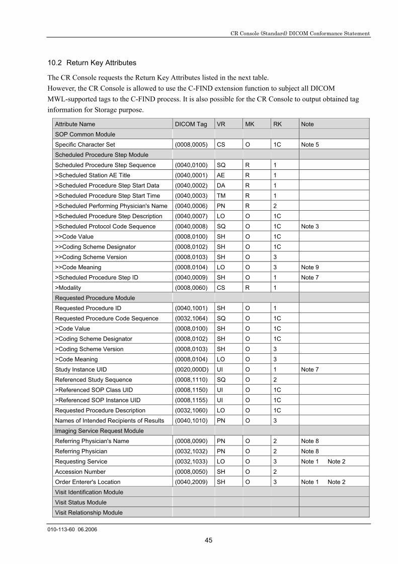
CR Console (Standard) DICOM Conformance Statement
010-113-60 06.2006
45
10.2 Return Key Attributes
The CR Console requests the Return Key Attributes listed in the next table. However, the CR Console is allowed to use the C-FIND extension function to subject all DICOM MWL-supported tags to the C-FIND process. It is also possible for the CR Console to output obtained tag information for Storage purpose.
Attribute Name DICOM Tag VR MK RK Note
SOP Common Module
Specific Character Set (0008,0005) CS O 1C Note 5
Scheduled Procedure Step Module
Scheduled Procedure Step Sequence (0040,0100) SQ R 1
>Scheduled Station AE Title (0040,0001) AE R 1
>Scheduled Procedure Step Start Data (0040,0002) DA R 1
>Scheduled Procedure Step Start Time (0040,0003) TM R 1
>Scheduled Performing Physician's Name (0040,0006) PN R 2
>Scheduled Procedure Step Description (0040,0007) LO O 1C
>Scheduled Protocol Code Sequence (0040,0008) SQ O 1C Note 3
>>Code Value (0008,0100) SH O 1C
>>Coding Scheme Designator (0008,0102) SH O 1C
>>Coding Scheme Version (0008,0103) SH O 3
>>Code Meaning (0008,0104) LO O 3 Note 9
>Scheduled Procedure Step ID (0040,0009) SH O 1 Note 7
>Modality (0008,0060) CS R 1
Requested Procedure Module
Requested Procedure ID (0040,1001) SH O 1
Requested Procedure Code Sequence (0032,1064) SQ O 1C
>Code Value (0008,0100) SH O 1C
>Coding Scheme Designator (0008,0102) SH O 1C
>Coding Scheme Version (0008,0103) SH O 3
>Code Meaning (0008,0104) LO O 3
Study Instance UID (0020,000D) UI O 1 Note 7
Referenced Study Sequence (0008,1110) SQ O 2
>Referenced SOP Class UID (0008,1150) UI O 1C
>Referenced SOP Instance UID (0008,1155) UI O 1C
Requested Procedure Description (0032,1060) LO O 1C
Names of Intended Recipients of Results (0040,1010) PN O 3
Imaging Service Request Module
Referring Physician's Name (0008,0090) PN O 2 Note 8
Referring Physician (0032,1032) PN O 2 Note 8
Requesting Service (0032,1033) LO O 3 Note 1 Note 2
Accession Number (0008,0050) SH O 2
Order Enterer's Location (0040,2009) SH O 3 Note 1 Note 2
Visit Identification Module
Visit Status Module
Visit Relationship Module

CR Console (Standard) DICOM Conformance Statement
010-113-60 06.2006
46
Referenced Patient Sequence (0008,1120) SQ O 2
>Referenced SOP Class UID (0008,1150) UI O 2
>Referenced SOP Instance UID (0008,1155) UI O 2
Visit Admission Module
Patient Relationship Module
Patient Identification Module
Patient's Name (0010,0010) PN R 1 Note 4
Patient ID (0010,0020) LO R 1
Other Patient IDs (0010,1000) LO O 3
Patient Demographic Module
Patients Birth Date (0010,0030) DA O 3
Patient's Sex (0010,0040) CS O 2
Ethnic Group (0010,2160) SH O 3
Patient Comments (0010,4000) LT O 3
Patient Medical Module
Patient State (0038,0500) LO O 2
Pregnancy Status (0010,21C0) US O 2
Additional Patient History (0010,21B0) LT O 3
Radiation Dose Module Note 6
Radiation Dose Sequence (0040,030E) SQ O 3 Note 6
>Exposure Type (0018,115A) CS O 3 Note 6
>KVp (0018,0060) DS O 1C Note 6
>X-ray Tube Current in µA (0018,8151) DS O 1C Note 6
>Exposure Time (0018,1150) IS O 1C Note 6
>Filter Type (0018,1160) LO O 3 Note 6
>Filter Material (0018,7050) CS O 3 Note 6
Study Component Acquisition Note 8
Study Description (0008,1030) LO O 3 Note 8
Image Acquisition Results Module Note 8
Study ID (0020,0010) SH O 3 Note 8
Private Note 8
Distribution Code (0009,xx90) ST O 3 Note 8
Number of Films (2000,0010) IS O 3 Note 10
Note 1 How to set up a requesting department name. 1) When setting up a requesting department name both in 1- and 2-byte characters.
Requesting department name in 1-byte characters: (0040, 2009) Order Enterer’s Location - A maximum of 64 characters Requesting department name in 2-byte characters: (0032, 1033) Requesting Service - A maximum of 8 characters
2) When setting up a requesting department name only in 2-byte characters. Requesting department name in 2-byte characters: (0032, 1033) Requesting Service - A maximum of 8 characters
3) When setting up a requesting department name only in 1-byte characters. Requesting department name in 1-byte characters: (0032, 1033) Requesting Service - A maximum of 64 characters * Note that for 1) and 2) above, characters can be corrupted on output devices, such as filer or printer.

CR Console (Standard) DICOM Conformance Statement
010-113-90 06.2007
47
Note 2 1- and 2-byte characters cannot be used mixed at the same time.
Note 3 JJ1017-compliance rules A set of three items consisting of (1) study details, (2) target body part and (3) exposure direction is equivalent to one exposure (one exposure menu) in the “Scheduled Protocol Code Sequence”. Components included in (1), (2) and (3) cannot be omitted or repeated.
Item No. of Items (1) Study details 1 (2) Target body part 1 (3) Exposure direction 1
The length of Code Value character string in (1), (2) and (3) must not exceed a maximum of 16 characters.
The Scheduled Protocol Code Sequence complies with the JJ1017 Guidelines Ver. 1.1.
Note 4 How to handle a patient name (PN) with the Japanese environment.
Element Character Type Window Display
Film Display Distribution
1st element (notational representation)
1-byte characters only.
2nd element (ideographic representation)
2-byte characters only.
3rd element (phonetic representation)
Only 1- or 2-byte characters. × ×
Note 5 “ISO 2022 IR 13\ISO 2022 IR 87” will be transmitted using “C-FIND-RQ” with the Japanese
environment. “ISO IR100” can be set up within the English environment.
Note 6 These items will not be set up with the JJ1017 Guidelines.
Note 7 How to identify the same studies. Orders for which (0020, 000D) Study Instance UID and (0040, 0100)>(0040, 0009) Scheduled Procedure Step ID match with each other will be identified to be the same study. When studies for which the above two items match with each other have already been performed on the CR Console, a study cannot be started after receiving a relevant order.
Note 8 Tag information that has been set up according to the MWL support version for the IDT is now added.
Note 9 Can be set up for the name of a body part to be exposed and displayed on the study window.
Note 10 Film count to be set up for all Scheduled Protocol items.

CR Console (Standard) DICOM Conformance Statement
010-113-60 06.2006
48
11. Modality Performed Procedure Step IOD Attribute Overview
The CR Console provides the attributes listed in the next table.
Performed Procedure Step
Attribute Name Tag N-CREATE N_SET Final
fromModalityWorklist
CommonSOP Class UIDInstance UIDSpecific Character Set (0008,0005) 1C/1C Not allowed 0008,0005
Performed Procedure Step RelationshipScheduled Step Attribute Sequence (0040,0270) 1/1 Not allowed ->Study Instance UID (0020,000D) 1/1 Not allowed 0020,000D>Referenced Study Sequence (0008,1110) 2/2 Not allowed 0008,1110>>Referenced SOP Class UID (0008,1150) 1C/1 Not allowed 0008,1150>>Referenced SOP Instance UID (0008,1155) 1C/1 Not allowed 0008,1155>Accession Number (0008,0050) 2/2 Not allowed 0008,0050>Requested Procedure ID (0040,1001) 2/2 Not allowed 0040,1001>Requested Procedure Description (0032,1060) 2/2 Not allowed 0032,1060>Scheduled Procedure Step ID (0040,0009) 2/2 Not allowed 0040,0009>Scheduled Procedure Step Description (0040,0007) 2/2 Not allowed 0040,0007>Scheduled Action Item Code Sequence (0040,0008) 2/2 Not allowed 0040,0008>>Code Value (0008,0100) 1C/1 Not allowed 0008,0100>>Coding Scheme Designator (0008,0102) 1C/1 Not allowed 0008,0102>>Coding Scheme Version (0008,0103) 3/3 Not allowed 0008,0103>>Code Meaning (0008,0104) 3/3 Not allowed 0008,0104Patient's Name (0010,0010) 2/2 Not allowed 0010,0010Patient ID (0010,0020) 2/2 Not allowed 0010,0020Patient's Birth Data (0010,0030) 2/2 Not allowed 0010,0030Patient's Sex (0010,0040) 2/2 Not allowed 0010,0040Referenced Patient Sequence (0008,1120) 2/2 Not allowed 0008,0120>Referenced SOP Class UID (0008,1150) 1C/1 Not allowed 0008,1150>Referenced Instance UID (0008,1155) 1C/1 Not allowed 0008,1155
Performed Procedure Step InformationPerformed Procedure Step ID (0040,0253) 1/1 Not allowedPerformed Station AE Title (0040,0241) 1/1 Not allowedPerformed Station Name (0040,0242) 2/2 Not allowedPerformed Location (0040,0243) 2/2 Not allowedPerformed Procedure Step Start Data (0040,0244) 1/1 Not allowedPerformed Procedure Step Start Time (0040,0245) 1/1 Not allowedPerformed Procedure Step Status (0040,0252) 1/1 3/1Performed Procedure Step End Data (0040,0250) 2/2 3/1 1Performed Procedure Step End Time (0040,0251) 2/2 3/1 1Performed Procedure Step (0040,0254) 2/2 3/2Performed Procedure Type (0040,0255) 2/2 3/2Comments on the Performed Procedure Step (0040,0280) 3/3 3/3Procedure Code Sequence (0008,1032) 2/2 3/2>Code Value (0008,0100) 1C/1 1C/1>Coding Scheme Designator (0008,0102) 1C/1 1C/1>Coding Scheme Version (0008,0103) 3/3 3/3>Code Meaning (0008,0104) 3/3 3/3

CR Console (Standard) DICOM Conformance Statement
010-113-60 06.2006
49
Image Acquisition ResultsModality (0008,0060) 1/1 Not allowed 0008,0060Study ID (0020,0010) 2/2 Not allowed 0040,1001Performed Action Item Code Sequence (0040,0260) 2/2 3/2 0040,0008>Code Value (0008,0100) 1C/1 1C/1 0008,0100>Coding Scheme Designator (0008,0102) 1C/1 1C/1 0008,0102>Coding Scheme Version (0008,0103) 1C/1 1C/1 0008,0103>Code Meaning (0008,0104) 3/3 3/3 0008,0104Performed Series Sequence (0040,0340) 2/2 3/1 1>Series Description (0008,103E) 2C/2 2C/2 2>Retrieve AE Title (0008,0054) 2C/2 2C/2 2>Performed Physisian's Name (0008,1050) 2C/2 2C/2>Operator's Name (0008,1070) 2C/2 2C/2>Protocol Name (0018,1030) 1C/1 1C/1 1>Series Instance UID (0020,000E) 1C/1 1C/1 1>Referenced Image Sequence (0008,1140) 2C/2 2C/2 1C>>Referenced SOP Class UID (0008,1150) 1C/1 1C/1>>Referenced SOP Instance UID (0008,1155) 1C/1 1C/1>Referenced Non-Image Composite SOP InstanceSequence (0040,0220) 2C/2 2C/2 1C>>Referenced SOP Class UID (0008,1150) 1C/1 1C/1>>Referenced SOP Instance UID (0008,1155) 1C/1 1C/1
Radiation DoseRadiation Dose Sequence (0040,030E) 3/3 3/3>Exposure Type (0018,115A) 3/3 3/3>KVp (0018,0060) 3/3 3/3>X-ray Tube Current in µA (0018,8151) 3/3 3/3>Exposure Time (0018,1150) 3/3 3/3>Filter Type (0018,1160) 3/3 3/3>Filter Material (0018,7050) 3/3 3/3
Billing and Material Management CodeFilm Consumption Sequence (0040,0321) 3/3 3/3>Number of Films (2100,0170) 3/3 3/3>Film Size ID (2010,0050) 3/3 3/3Billing Supplies and Devices Sequence (0040,0324) 3/3 3/3>Billing Item Sequence (0040,0296) 3/3 3/3>>Code Value (0008,0100) 1C/1 1C/1>>Coding Scheme Designator (0008,0102) 1C/1 1C/1>>Coding Scheme Version (0008,0103) 3/3 3/3>>Code Meaning (0008,0104) 3/3 3/3>Quantity Sequence (0040,0293) 3/3 3/3>>Quantity (0040,0294) 3/3 3/3
Exposure Status (Private Tag)Exposure Status Sequence (0019,XXA0) 3/3 3/3>Distance Source to Detector (0018,1110) 3/3 3/3>Exposure (0018,1152) 3/3 3/3>Exposure in µAs (0018,1153) 3/3 3/3>Grid (0018,1166) 3/3 3/3>Estimated Radiographic Magnification Factor (0018,1114) 3/3 3/3>Image Area Dose Product (0018,115E) 3/3 3/3>Anode Target Material (0018,1191) 3/3 3/3>Body Part Thickness (0018,11A0) 3/3 3/3>Compression Force (0018,11A2) 3/3 3/3>Positioner Primary Angle (0018,1510) 3/3 3/3>Exposure Division Count (0019,YY71) 1C/1 1C/1>Exposure Status (0019,YYA1) 1C/1 1C/1>Exposure Kind (0019,YYA2) 1C/1 1C/1>Entrance Dose (0040,0302) 3/3 3/3>Organ Dose (0040,0316) 3/3 3/3>Entrance Dose in mGy (0040,8302) 3/3 3/3

CR Console (Standard) DICOM Conformance Statement
010-113-60 06.2006
50
X-ray Acquisition Dose Module Name Tag VR VM Description of Attributes
Radiation Dose Sequence
(0040,030E) SQ
1 Exposure Dose Sequence will contain Total Number of Exposures (0040, 0301) items plus an item for each fluoroscopy episode not already counted as an exposure.
>KVp (0018,0060) DS1 Peak kilo voltage output of the x-ray generator used.
An average in the case of fluoroscopy (continuous radiation mode).
>Exposure Time (0018,1150) IS 1 Time of x-ray exposure or fluoroscopy in msec.
>Exposure Type (0018,115A) CS
1 Specifies X-Ray radiation mode. Enumerated Values:
CONTINUOUS PULSED
>Filter Type (0018,1160) LO1 Type of filter(s) inserted into the X-Ray beam (e.g.
wedges).
>Filter Material (0018,7050) CS
1 The X-Ray absorbing material used in the filter. May be multi-valued. Values:
MOLYBDENUM RHODIUM ALUMINUM
>X-ray Tube Current in µA (0018,8151) DS1 X-ray Tube Current in µA. An average in the case of
fluoroscopy (continuous radiation mode).
Attributes of Exposure Status Sequence
Name Tag VR VM Description of Attributes
Exposure Status Sequence (0019,XXA0) SQ 1 Sequence that indicates exposure status. >Distance Source to Detector
(0018,1110) DS 1 Distance in mm from the source to detector center;
>Exposure (0018,1152) IS 1 The exposure expressed in mAs, for example alculated from Exposure Time and X-ray Tube Current.
>Exposure in µAs (0018,1153) IS 1 The exposure expressed in µAs, for example calculated from Exposure Time and X-ray Tube Current.
>Grid (0018,1166) CS 1 Identify the grid. Only a single value shall be present. Defined Terms:
USED : Grid is used. NONE : Grid is not used.
>Estimated Radiographic Magnification Factor
(0018,1114) DS 1 Ratio of Source Image Distance (SID) over Source Object Distance (SOD).
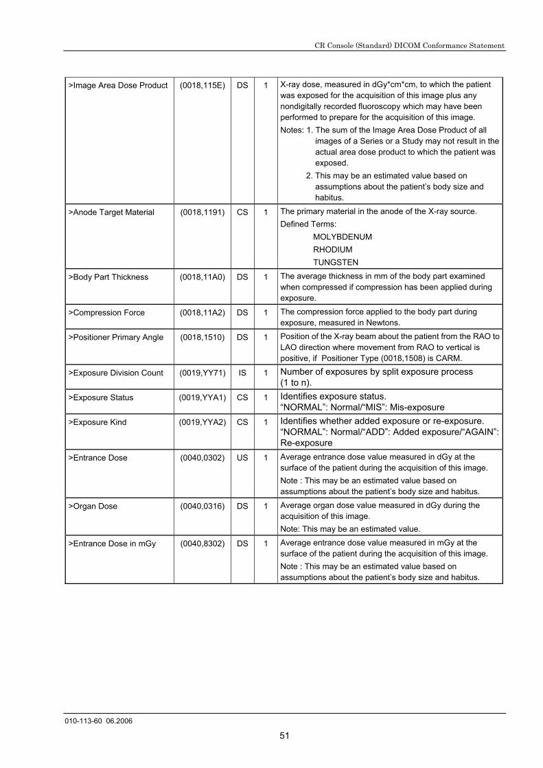
CR Console (Standard) DICOM Conformance Statement
010-113-60 06.2006
51
>Image Area Dose Product (0018,115E) DS 1 X-ray dose, measured in dGy*cm*cm, to which the patient was exposed for the acquisition of this image plus any nondigitally recorded fluoroscopy which may have been performed to prepare for the acquisition of this image. Notes: 1. The sum of the Image Area Dose Product of all
images of a Series or a Study may not result in the actual area dose product to which the patient was exposed.
2. This may be an estimated value based on assumptions about the patient’s body size and habitus.
>Anode Target Material (0018,1191) CS 1 The primary material in the anode of the X-ray source. Defined Terms:
MOLYBDENUM RHODIUM TUNGSTEN
>Body Part Thickness (0018,11A0) DS 1 The average thickness in mm of the body part examined when compressed if compression has been applied during exposure.
>Compression Force (0018,11A2) DS 1 The compression force applied to the body part during exposure, measured in Newtons.
>Positioner Primary Angle (0018,1510) DS 1 Position of the X-ray beam about the patient from the RAO to LAO direction where movement from RAO to vertical is positive, if Positioner Type (0018,1508) is CARM.
>Exposure Division Count (0019,YY71) IS 1 Number of exposures by split exposure process (1 to n).
>Exposure Status (0019,YYA1) CS 1 Identifies exposure status. “NORMAL”: Normal/“MIS”: Mis-exposure
>Exposure Kind (0019,YYA2) CS 1 Identifies whether added exposure or re-exposure. “NORMAL”: Normal/“ADD”: Added exposure/“AGAIN”: Re-exposure
>Entrance Dose (0040,0302) US 1 Average entrance dose value measured in dGy at the surface of the patient during the acquisition of this image. Note : This may be an estimated value based on assumptions about the patient’s body size and habitus.
>Organ Dose (0040,0316) DS 1 Average organ dose value measured in dGy during the acquisition of this image. Note: This may be an estimated value.
>Entrance Dose in mGy (0040,8302) DS 1 Average entrance dose value measured in mGy at the surface of the patient during the acquisition of this image. Note : This may be an estimated value based on assumptions about the patient’s body size and habitus.
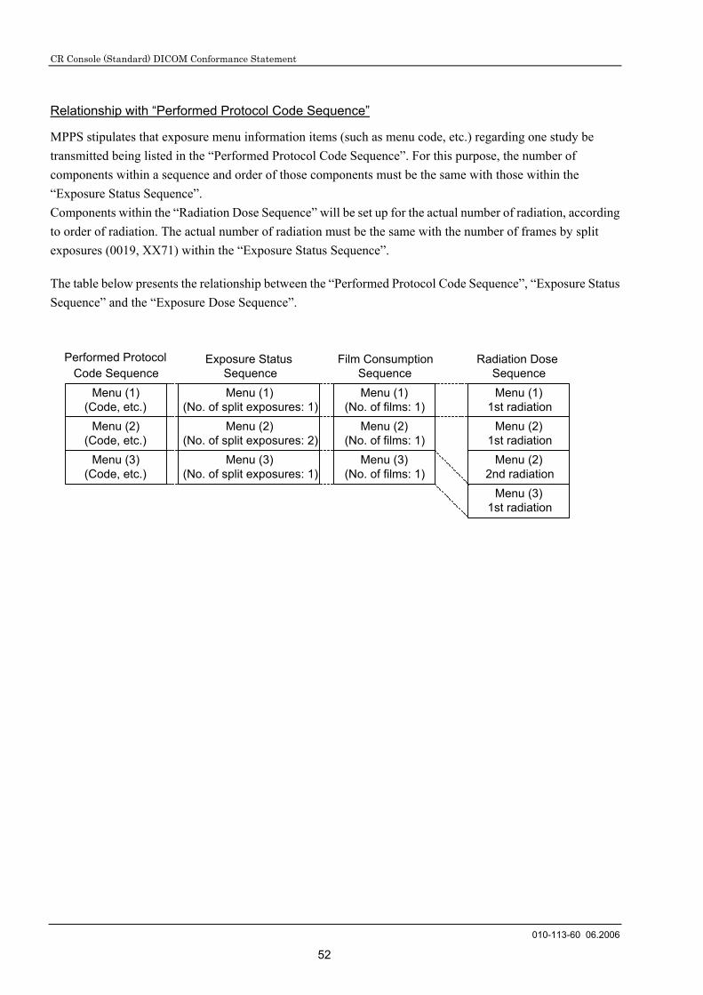
CR Console (Standard) DICOM Conformance Statement
010-113-60 06.2006
52
Relationship with “Performed Protocol Code Sequence”
MPPS stipulates that exposure menu information items (such as menu code, etc.) regarding one study be transmitted being listed in the “Performed Protocol Code Sequence”. For this purpose, the number of components within a sequence and order of those components must be the same with those within the “Exposure Status Sequence”. Components within the “Radiation Dose Sequence” will be set up for the actual number of radiation, according to order of radiation. The actual number of radiation must be the same with the number of frames by split exposures (0019, XX71) within the “Exposure Status Sequence”.
The table below presents the relationship between the “Performed Protocol Code Sequence”, “Exposure Status Sequence” and the “Exposure Dose Sequence”.
Menu (1)(Code, etc.)
Menu (2)(Code, etc.)
Menu (3)(Code, etc.)
Menu (1)(No. of split exposures: 1)
Menu (2)(No. of split exposures: 2)
Menu (3)(No. of split exposures: 1)
Performed ProtocolCode Sequence
Exposure StatusSequence
Radiation DoseSequenceMenu (1)
1st radiationMenu (2)
1st radiationMenu (2)
2nd radiationMenu (3)
1st radiation
Menu (1)(No. of films: 1)
Menu (2)(No. of films: 1)
Menu (3)(No. of films: 1)
Film ConsumptionSequence

CR Console (Standard) DICOM Conformance Statement
010-113-90 06.2007
53
12. Modality Worklist for Patient Information (MWM PI) Query/Retrieve Attribute Overview
12.1 Matching Key Attributes
Matching key attributes Tag Matching key type Matching type
Patient ID 0010,0020 R Single Accession Number 0008,0050 O Single
12.2 Return Key Attributes
The CR Console requests the Return Key Attributes listed in the next table.
Attribute Name DICOM Tag VR MK RK Note
SOP Common Module
Specific Character Set (0008,0005) CS O 1C Note 1
Imaging Service Request Module
Accession Number (0008,0050) SH O 2
Patient Identification Module
Patient's Name (0010,0010) PN R 1 Note 2
Patient ID (0010,0020) LO R 1
Patient Demographic Module
Patients Birth Date (0010,0030) DA O 3
Patient's Sex (0010,0040) CS O 2
Note 1 “ISO 2022 IR 13\ISO 2022 IR 87” will be transmitted using “C-FIND-RQ” with the Japanese environment. “ISO IR100” can be set up within the English environment.
Note 2 How to handle a patient name (PN) with the Japanese environment.
Element Character Type Window Display
Film Display Distribution
1st element (notational representation)
1-byte characters only.
2nd element (ideographic representation)
2-byte characters only.
3rd element (phonetic representation)
Only 1- or 2-byte characters. × ×
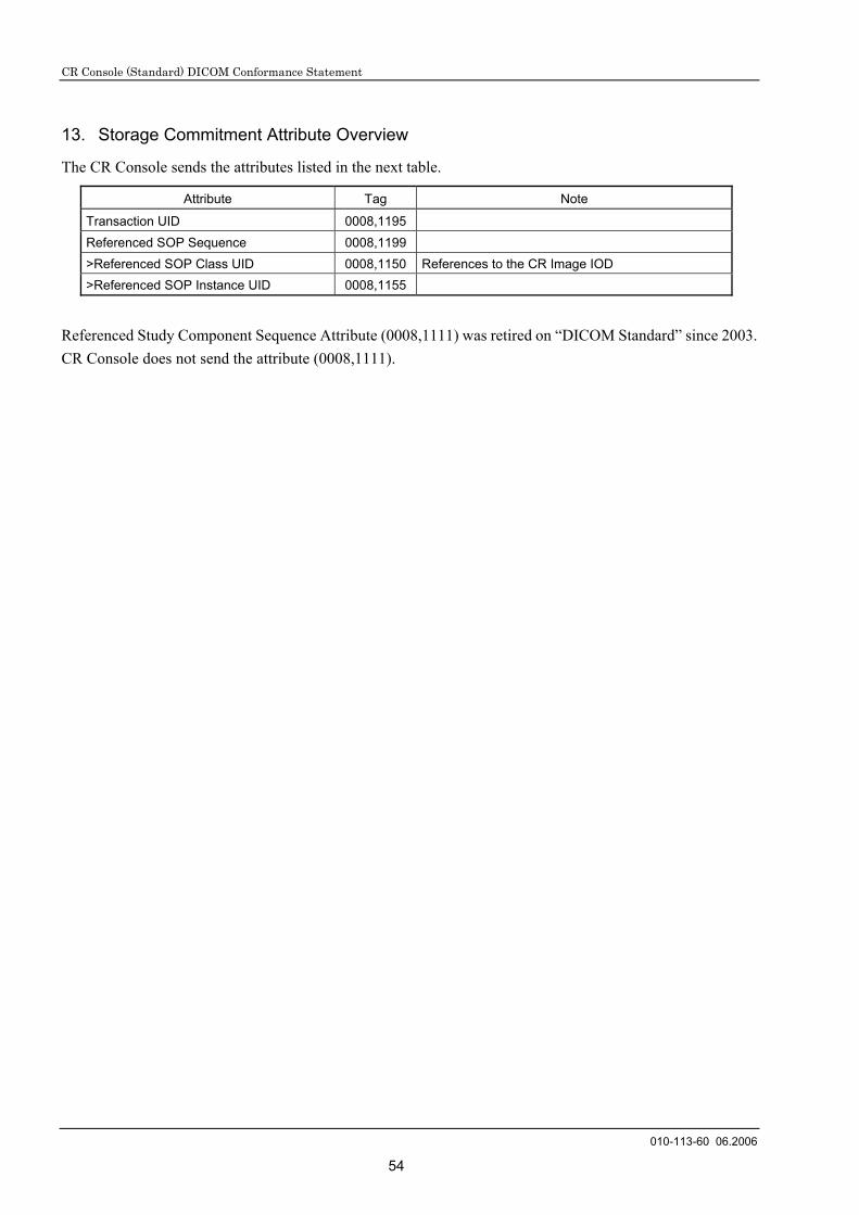
CR Console (Standard) DICOM Conformance Statement
010-113-60 06.2006
54
13. Storage Commitment Attribute Overview
The CR Console sends the attributes listed in the next table.
Attribute Tag Note
Transaction UID 0008,1195 Referenced SOP Sequence 0008,1199 >Referenced SOP Class UID 0008,1150 References to the CR Image IOD >Referenced SOP Instance UID 0008,1155
Referenced Study Component Sequence Attribute (0008,1111) was retired on “DICOM Standard” since 2003. CR Console does not send the attribute (0008,1111).

CR Console (Standard) DICOM Conformance Statement
010-113-60 06.2006
55
14. DIMSE-Service and Attributes in the Basic Grayscale Print Management
14.1 DIMSE-Service
SOP Class DIMSE Usage SCU Usage Basic Film Session SOP Class N-CREATE M Used. N-SET U Not used. N-DELETE U Used. N-ACTION U Not used. Basic Film Box SOP Class N-CREATE M Used. N-SET U Not used. N-DELETE U Used. N-ACTION M Used. Image Box SOP Class N-SET M Used. Printer SOP Class N-EVENT-REPORT M Used. N-GET U Used.
14.2 Basic Film Session SOP Class
N-CREATE Name Tag Value
Number of Copies 2000,0010 1-9 Print Priority 2000,0020 Specifies the priority of the print job.
Enumerated Values: HIGH MED LOW
Medium Type 2000,0030 CLEAR FILM BLUE FILM
Film Destination 2000,0040 PROCESSOR BIN_i
Memory Allocation 2000,0060 39219, 71438
14.3 Basic Film Box SOP Class
N-CREATE Name Tag Value
Image Display Format 2010,0010 STANDARD \1,1 Film Orientation 2010,0040 PORTRAIT
LANDSCAPE Film Size ID 2010,0050 8INX10IN,
10INX12IN, 10INX14IN, 14INX14IN, 14INX17IN
Magnification Type 2010,0060 REPLICATE, BILINEAR, CUBIC, NONE
Smoothing Type 2010,0080 SHARP SMOOTH MEDIUM

CR Console (Standard) DICOM Conformance Statement
010-113-60 06.2006
56
Border Density 2010,0100 BLACK WHITE 0-300
Max Density 2010,0130 360,300 Trim 2010,0140 NO Configuration Information 2010,0150 “1” - “8”,
”FINE1” - “FINE8” Referenced Film Session Sequence 2010,0500 Referenced SOP Class UID >0008,1150 1.2.840.10008.5.1.1.1 Referenced SOP Instance UID >0008,1155 From created Film Session SOP Instance.
14.4 Basic Grayscale Image Box SOP Class
N-SET
Name Tag Value Smoothing Type 2010,0080 SHARP
SMOOTH MEDIUM
Max Density 2010,0130 360,300 Configuration Information 2010,0150 “1” - “8”,
”FINE1” - “FINE8” Image Position 2020,0010 1 Requested Image Size 2020,0030 Depend on Image Size and Film Format. Requested Decimate/Crop 2020,0040 “CROP” or with no tags. Basic Grayscale Image Sequence 2020,0110 1 Photometric Interpretation >0028,0004 MONOCHROME1 Rows >0028,0010 Depend on Image Size and Film Format. Columns >0028,0011 Depend on Image Size and Film Format. Bits Allocated >0028,0100 16 Bits Stored >0028,0101 10 High Bit >0028,0102 9 Pixel Representation >0028,0103 0 Pixel Data >7FE0,0010 Pixels of rendered film sheet.
14.5 Printer SOP Class
N-EVENT-REPORT
Event Type Name Event Type ID Attribute Tag Usage Normal 1 Warning 2 Printer Name 2110,0030 U Printer Status Info 2110,0020 U Failure 3 Printer Name 2110,0030 U Printer Info 2110,0020 U
N-GET
Name Tag UsagePrinter Status 2110,0010 U Printer Status Info 2110,0020 U

CR Console (Standard) DICOM Conformance Statement
010-113-60 06.2006
57

26-30, NISHIAZABU 2-CHOME, MINATO-KU, TOKYO 106-8620, JAPAN


