BIRKS: DIELECTRIC HOUSINGS FOR CENTIMETRE-WAVE ANTENNAE 653 Part 2. DESIGN PRACTICE FOR AIRBORNE RADAR SUMMARY Various practical aspects of the design of dielectric antenna housings (or radomes) for airborne centimetre-wave radar systems are dis- cussed. The effects of radomes on the performance, and particularly on the gain, impedance, polar diagram and polarization of the antenna are described, with a number of practical examples. The aerodynamic considerations which affect radome design are summarized. An account is given of the development and use of various materials for 10- and 3-cm radomes. The materials and structures discussed include polymethyl methacrylate, low pressure resins, laminated fibre- glass, expanded dielectrics, and double-wall and sandwich structures. The work was carried out at the Telecommunications Research Establishment during 1942-45. If G o is the power gain of the aerial when it is radiating into free space, and T the power-transmission coefficient of the radome, then the effective gain of the system is (12) INTRODUCTION In Part 1 of this paper, the theory of the transmission and reflection of electromagnetic waves by dielectric sheets has been considered, with particular reference to dielectric housings for centimetre-wave antennae. The purpose of the present paper is to discuss the practical aspects of the design of such housings for airborne centimetre-wave radar systems, and to give an account of recent developments. The prime advantage of the use of centimetre waves for air- borne radar is that narrow-beam antenna systems may be designed, sufficiently small to be carried in an aircraft, yet having the requisite high discrimination and gain. A radar system normally has a dual function to perform, the initial search for the target, and its accurate location. The latter requirement is met by the use of a narrow beam (in addition to a narrow or steep pulse, a rapid time-base, etc.), and the former by scanning, i.e. movement of the antenna beam to sweep the required volume of space. Except in a few applications, where "electrical" scanning is used (e.g. the beam from a wave- guide linear array may be swung by varying the width of the wave guide), the scanning is produced by a mechanical move- ment of the antenna system. Since such movement is imprac- ticable with the antenna system (or scanner, as it is usually called) mounted externally to the aircraft in the airstream, the scanner is mounted in a dielectric housing." Such housings have been known variously as scanner fairings, cupolas, blisters, noses, turrets, nacelles, etc., but the descriptive term, radomes, coined by the Americans, is now generally adopted. A radome is an integral part of the antenna system, since unless it is properly designed, it may modify appreciably the characteristics of the antenna, such as its power gain, impedance and polar diagram. The radome is also a part of the aircraft structure, and may affect its performance, serviceability and air- worthiness. The essence of radome design technique consists therefore of reconciling these two requirements. (13) EFFECTS ON ANTENNA PERFORMANCE An electromagnetic wave incident on a dielectric structure is modified on transmission through the dielectric. Part of the incident power, R, is reflected and a further part, A, is absorbed. The power transmission coefficient T (ratio of transmitted to incident power) is given by r =- 1 - R- A (58) T, R, A are functions of the wavelength, the thickness and nature of the dielectric, and also of the angle of incidence and polariza- tion of the incident wave. (13.1) Reduction in Gain The reduction of power on transmission through a radome is equivalent to a reduction in the gain of the antenna system. G = G Q T . and the radar range is reduced from L Q to L = (59) (60) In a well-designed radome, T is normally 0-90 to 0-98, corre- sponding to a reduction of 1 to 5 % in range. (13.2) Change in Impedance: Frequency-Pulling Part of the power incident on the radome may be reflected back into the antenna feed, causing a change in antenna impe- dance and a corresponding change in the load impedance and frequency of the transmitting magnetron. Since, in general, the relative positions of the antenna and radome change during the scanning cycle, the amplitude and phase of the wave reflected back into the antenna is a function of the scanner position, giving a variation of antenna impedance, and a consequent pulling of the magnetron frequency, during the scan. Any initial mismatch in the antenna increases the effect. Frequency- pulling due to radome reflection is more marked at the longer wavelengths, where the radome curvature is small compared to the wavelength, so that the phase of the reflected wave-front from a section of the radome is practically uniform. The effect was particularly troublesome on some of the earlier centimetre-wave radar systems, where reflection from certain areas of the radome was sufficient to pull the transmitter fre- quency outside the band-width of the i.f. receiver, giving blank areas on the display. Even when the effect is less pronounced it may lead to reduced signals and loss of range in certain sectors, due to part of the transmitted (and hence the received) pulse being outside the receiver band-width. In practice, frequency- pulling is overcome by one or more of the following methods. (a) The use of a low-reflection radome structure. (b) The choice of a radome shape which avoids surfaces nearly normal to the antenna beam. (c) Automatic frequency control of the local oscillator. (13.3) Change in Polar Diagram The radome may modify the antenna polar diagram in several ways. Four typical cases of pattern distortion will be described. (a) The simplest type is the amplitude distortion of a broad beam. In several radar equipments (e.g. H 2 S, A.S.V.) for use against targets on the ground or at sea-level, the elevation pattern is designed to give uniform coverage over the area illuminated (cosecant-squared pattern). If, however, the trans- mission coefficient of the radome varies for the different angles of elevation within the required coverage (as it normally does, due to the variation of the angle of incidence subtended by the beam at the radome), then the amplitude of the beam will be reduced non-uniformly, giving a distortion of the cosecant- squared pattern and possibly gaps in the coverage of the equip- ment. By designing the radome to give optimum transmission over the range of incidence angles (if necessary, by varying the radome thickness), the amplitude distortions may be reduced to the same order as those introduced by slight imperfections in the design or manufacture of the antenna system. (b) In other applications, the radome may produce artificial side-lobes, for if the main beam from the antenna strikes the radome obliquely, the reflected energy may not impinge on the
Transcript
BIRKS: DIELECTRIC HOUSINGS FOR CENTIMETRE-WAVE ANTENNAE 653
Part 2. DESIGN PRACTICE FOR AIRBORNE RADAR
SUMMARYVarious practical aspects of the design of dielectric antenna housings
(or radomes) for airborne centimetre-wave radar systems are dis-cussed. The effects of radomes on the performance, and particularlyon the gain, impedance, polar diagram and polarization of the antennaare described, with a number of practical examples. The aerodynamicconsiderations which affect radome design are summarized.
An account is given of the development and use of various materialsfor 10- and 3-cm radomes. The materials and structures discussedinclude polymethyl methacrylate, low pressure resins, laminated fibre-glass, expanded dielectrics, and double-wall and sandwich structures.The work was carried out at the Telecommunications ResearchEstablishment during 1942-45.
If Go is the power gain of the aerial when it is radiating intofree space, and T the power-transmission coefficient of theradome, then the effective gain of the system is
(12) INTRODUCTIONIn Part 1 of this paper, the theory of the transmission and
reflection of electromagnetic waves by dielectric sheets has beenconsidered, with particular reference to dielectric housings forcentimetre-wave antennae. The purpose of the present paperis to discuss the practical aspects of the design of such housingsfor airborne centimetre-wave radar systems, and to give anaccount of recent developments.
The prime advantage of the use of centimetre waves for air-borne radar is that narrow-beam antenna systems may bedesigned, sufficiently small to be carried in an aircraft, yethaving the requisite high discrimination and gain. A radarsystem normally has a dual function to perform, the initialsearch for the target, and its accurate location. The latterrequirement is met by the use of a narrow beam (in additionto a narrow or steep pulse, a rapid time-base, etc.), and theformer by scanning, i.e. movement of the antenna beam to sweepthe required volume of space. Except in a few applications,where "electrical" scanning is used (e.g. the beam from a wave-guide linear array may be swung by varying the width of thewave guide), the scanning is produced by a mechanical move-ment of the antenna system. Since such movement is imprac-ticable with the antenna system (or scanner, as it is usuallycalled) mounted externally to the aircraft in the airstream, thescanner is mounted in a dielectric housing." Such housings havebeen known variously as scanner fairings, cupolas, blisters, noses,turrets, nacelles, etc., but the descriptive term, radomes, coinedby the Americans, is now generally adopted.
A radome is an integral part of the antenna system, sinceunless it is properly designed, it may modify appreciably thecharacteristics of the antenna, such as its power gain, impedanceand polar diagram. The radome is also a part of the aircraftstructure, and may affect its performance, serviceability and air-worthiness. The essence of radome design technique consiststherefore of reconciling these two requirements.
(13) EFFECTS ON ANTENNA PERFORMANCEAn electromagnetic wave incident on a dielectric structure is
modified on transmission through the dielectric. Part of theincident power, R, is reflected and a further part, A, is absorbed.The power transmission coefficient T (ratio of transmitted toincident power) is given by
r =- 1 - R- A (58)
T, R, A are functions of the wavelength, the thickness and natureof the dielectric, and also of the angle of incidence and polariza-tion of the incident wave.
(13.1) Reduction in GainThe reduction of power on transmission through a radome is
equivalent to a reduction in the gain of the antenna system.
G = GQT .
and the radar range is reduced from LQ to
L =
(59)
(60)
In a well-designed radome, T is normally 0-90 to 0-98, corre-sponding to a reduction of 1 to 5 % in range.
(13.2) Change in Impedance: Frequency-PullingPart of the power incident on the radome may be reflected
back into the antenna feed, causing a change in antenna impe-dance and a corresponding change in the load impedance andfrequency of the transmitting magnetron. Since, in general,the relative positions of the antenna and radome change duringthe scanning cycle, the amplitude and phase of the wave reflectedback into the antenna is a function of the scanner position,giving a variation of antenna impedance, and a consequentpulling of the magnetron frequency, during the scan. Anyinitial mismatch in the antenna increases the effect. Frequency-pulling due to radome reflection is more marked at the longerwavelengths, where the radome curvature is small compared tothe wavelength, so that the phase of the reflected wave-frontfrom a section of the radome is practically uniform.
The effect was particularly troublesome on some of the earliercentimetre-wave radar systems, where reflection from certainareas of the radome was sufficient to pull the transmitter fre-quency outside the band-width of the i.f. receiver, giving blankareas on the display. Even when the effect is less pronouncedit may lead to reduced signals and loss of range in certain sectors,due to part of the transmitted (and hence the received) pulsebeing outside the receiver band-width. In practice, frequency-pulling is overcome by one or more of the following methods.
(a) The use of a low-reflection radome structure.(b) The choice of a radome shape which avoids surfaces nearly
normal to the antenna beam.(c) Automatic frequency control of the local oscillator.
(13.3) Change in Polar DiagramThe radome may modify the antenna polar diagram in several
ways. Four typical cases of pattern distortion will be described.(a) The simplest type is the amplitude distortion of a broad
beam. In several radar equipments (e.g. H2S, A.S.V.) for useagainst targets on the ground or at sea-level, the elevationpattern is designed to give uniform coverage over the areailluminated (cosecant-squared pattern). If, however, the trans-mission coefficient of the radome varies for the different anglesof elevation within the required coverage (as it normally does,due to the variation of the angle of incidence subtended by thebeam at the radome), then the amplitude of the beam will bereduced non-uniformly, giving a distortion of the cosecant-squared pattern and possibly gaps in the coverage of the equip-ment. By designing the radome to give optimum transmissionover the range of incidence angles (if necessary, by varying theradome thickness), the amplitude distortions may be reduced tothe same order as those introduced by slight imperfections inthe design or manufacture of the antenna system.
(b) In other applications, the radome may produce artificialside-lobes, for if the main beam from the antenna strikes theradome obliquely, the reflected energy may not impinge on the
654 BIRKS: DIELECTRIC HOUSINGS FOR CENTIMETRE-WAVE ANTENNAE
antenna, but be re-radiated in some arbitrary direction. Atroublesome example of this effect occurred with an A.I. scannermounted in the nose of an aircraft. When the scanner wastilted upwards, during its scan, reflections from the upper partof the nose were directed vertically downwards, producingground clutter on the display in a scanner position where normalground echoes were absent. Such ground clutter interfered withthe normal functioning of the radar system, and a re-design ofthe upper part of the nose to reduce its reflection coefficient wasnecessary to eliminate the effect.
(c) A further type of polar-diagram effect is encountered withnarrow-beam antennae housed in cylindrical or spherical radomes.The reflected radiation from the radome may be brought to anapproximate focus at a point other than the antenna feed. Theenergy focused at this point acts as a subsidiary feed to theantenna, interfering with the energy distribution from theprimary feed. The resultant defocusing may cause a broadening
of the antenna beam and increased side-lobes. Fig. 5 shows theeffect observed with a 3-cm antenna system.
(d) Radar systems which employ split-beam antenna systems(i.e. the beam is switched rapidly and continuously between twopositions, a few degrees apart) to obtain high directional accuracy,are particularly vulnerable to radome effects. Any such effectthat discriminates between the two segments of the split beamwill produce a deviation in the split axis, and a correspondingerror in the line of sight. Ideally, in such cases, the rotationalaxis of the scanner should be located at the centre of a radomewhich is either spherical (for volume-scan) or cylindrical (forarea-scan), thus avoiding any change in the relative positions ofthe antenna beam and the radome.
(13.4) Change in PolarizationA wave transmitted obliquely through a dielectric sheet is not
only reduced in amplitude, but it also suffers, in general, achange of phase, a lateral displacement due to refraction, and achange of polarization.
This last effect is due to differences between the transmissioncoefficients of the components of the incident wave, polarizedperpendicular and parallel to the plane of incidence (see Part 1).
Suppose, for example, that a plane-polarized wave is incidentat 60° on a lossless sheet, permittivity 3, thickness A/6, and thatthe electric vector, <?, is at 45° to the plane of incidence. Thenthe wave may be resolved into two components, each of ampli-tude |#YV2|, polarized parallel and perpendicular to the incidentplane. The parallel component will be transmitted through thesheet without loss, since it is incident at the Brewster angle,(tan 60° = V3). The perpendicular component, however, will bereduced by reflection loss to |0 • 6(f/\/2| in amplitude. The ampli-tude of the transmitted wave will therefore be |(1 + 0-6)±#7V2|= v^O'S)^ and its plane of polarization will be rotated by45° - a r c tan 0-6== 14°.
We have, in the above example, neglected the difference ofphase between the two components which also occurs, so thatthe transmitted wave is, in general, elliptically polarized.
No major radome effects directly attributable to phase change,lateral displacement, or elliptical polarization have occurred inthe author's experience. Nevertheless they are importantpotential sources of polar-diagram distortion, particularly withthe acute curvatures and high incidence angles of finely stream-lined radomes.
(14) AERODYNAMIC CONSIDERATIONSA radome, as an external aircraft structure, must be designed
to withstand high aerodynamic stresses in flight, to have anadequate service life, and to cause minimum deterioration ofaircraft performance. A detailed discussion is outside the scopeof the present paper, but the more important factors whichinfluence the electrical design and the choice of materials willbe summarized.
(14.1) Strength and RigidityThe primary stresses on a radome in flight are in bending, so
that the most important mechanical properties of a radomematerial are flexural strength and rigidity. These are definedby My the breaking bending moment in lb-in/inch width, andEl, the stiffness in Ib-in2/inch width. Expressed in this form,the requirements are applicable to any type of radome con-struction.
For a uniform (single-sheet) material, M and El are relatedto the ultimate flexural strength, F, the flexural modulus ofelasticity, E, and the thickness, x, by
(61)
(62)
In practice, specified values of M range from 25 lb in/inch width(equivalent to i-in methacrylate) upwards.
Subsidiary mechanical requirements include impact strength(to prevent damage to the radome in handling, or in collisionwith small objects) and tensile and bolt-hole strength (to preventthe radome breaking away from its attachments in flight).
(14.2) Serviceability
A radome material must be serviceable over a wide tempera-ture range, which has been specified as follows. At temperaturesencountered in flight (— 50 to 25° C) the material must maintainthe required mechanical properties, and must not becomebrittle; at the maximum take-off temperature (40° C) the materialmust have at least 40% of the specified M and El; and it mustbe stable under light loading conditions at ground temperaturesup to 65° C.
In addition a suitable material must be inert to sunlight andgeneral atmospheric exposure, have a low moisture absorption,not support fungus growth, and be resistant to aircraft fluids.
BIRKS: DIELECTRIC HOUSINGS FOR CENTIMETRE-WAVE ANTENNAE 655
(14.3) Aircraft PerformanceWeight and drag are the two factors which influence aircraft
performance. The weight, which affects the range, fuel con-sumption and possibly the stability of the aircraft, should beminimized by the use of radome structures with a highstrength/weight ratio. The drag depends on the size, shape andlocation of the radome. The location is primarily determinedby the nature of the radar system, and the particular volume ofspace which it is required to scan. The usual positions forradomes are as follows.
(14.3.1) Nose.This is only available on multi-engined aircraft, and is used
for forward-looking systems, such as A.I. It is also used fordownward-looking systems such as H2S, on high-speed aircraft,rearward coverage being sacrified to minimize drag.
(14.3.2) Tail Turret.The tail-turret position is also used for rearward-looking
applications, such as tail-warning devices.
(14.3.3) Under-FuselageThe under-fuselage position is normally used for systems, such
as H2S and A.S.V., which require all-round coverage of thelower hemisphere.(14.3.4) Under-Wing.
With single-engined aircraft a radome position under thewing may be adopted. A further interesting application occurredin the installation of A.S.V. in flying-boats. Since the fuselagealso functioned as the hull, it was impracticable to mount theradome under the fuselage. Two scanners were therefore used,mounted in radomes under the two wings out-board of theengines, and rotated in synchronism and fed by a wave-guide froma common transmitter, power being switched from one scannerto the other every half-cycle, to give full 360° coverage.
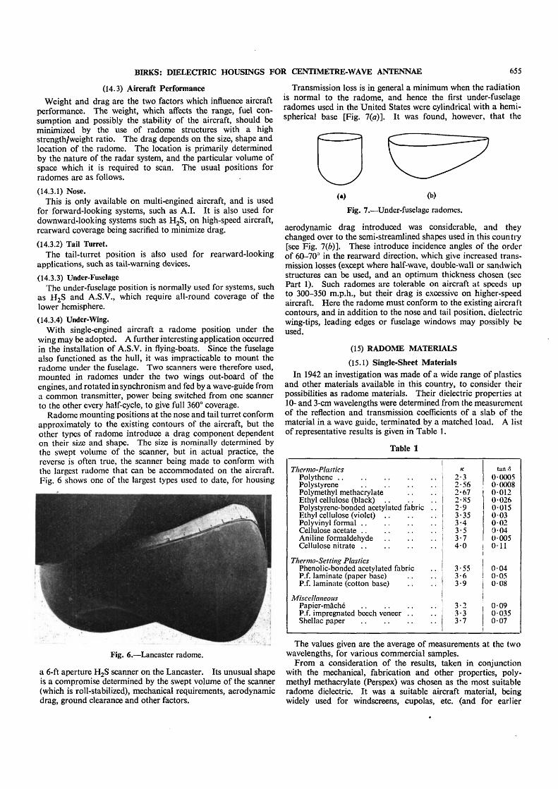
Radome mounting positions at the nose and tail turret conformapproximately to the existing contours of the aircraft, but theother types of radome introduce a drag component dependenton their size and shape. The size is nominally determined bythe swept volume of the scanner, but in actual practice, thereverse is often true, the scanner being made to conform withthe largest radome that can be accommodated on the aircraft.Fig. 6 shows one of the largest types used to date, for housing
Fig. 6.—Lancaster radome.
a 6-ft aperture H2S scanner on the Lancaster. Its unusual shapeis a compromise determined by the swept volume of the scanner(which is roll-stabilized), mechanical requirements, aerodynamicdrag, ground clearance and other factors.
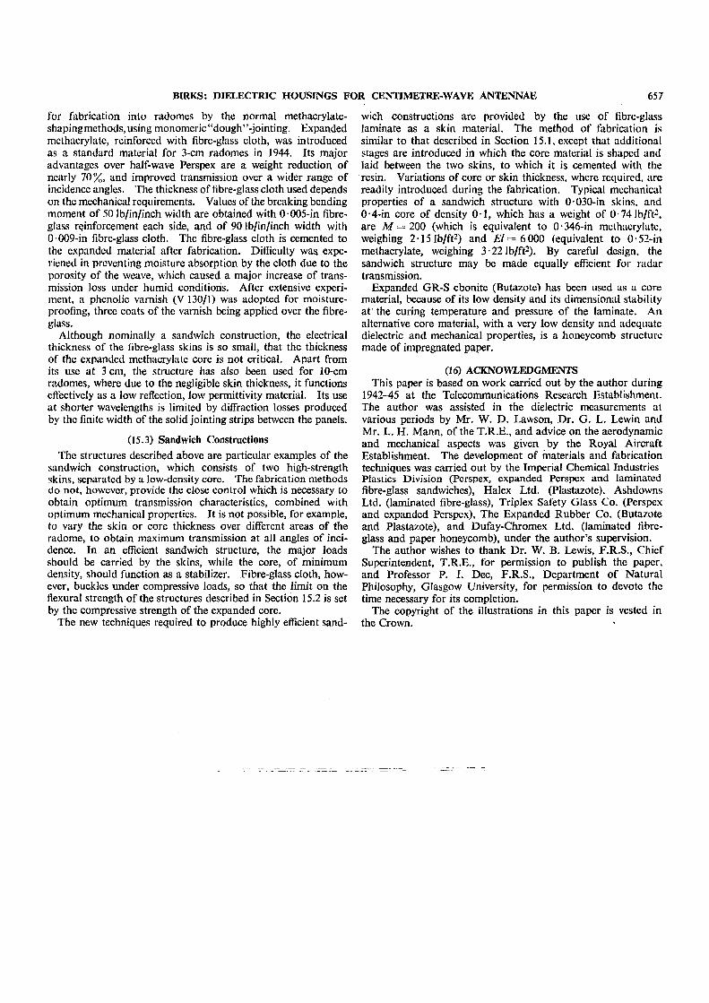
Transmission loss is in general a minimum when the radiationis normal to the radome, and hence the first under-fuselageradomes used in the United States were cylindrical with a hemi-spherical base [Fig. 7(a)]. It was found, however, that the
Fig. 7.—Under-fuselage radomes.
aerodynamic drag introduced was considerable, and theychanged over to the semi-streamlined shapes used in this country[see Fig. 7(6)]. These introduce incidence angles of the orderof 60-70° in the rearward direction, which give increased trans-mission losses (except where half-wave, double-wall or sandwichstructures can be used, and an optimum thickness chosen (seePart 1). Such radomes are tolerable on aircraft at speeds upto 300-350 m.p.h., but their drag is excessive on higher-speedaircraft. Here the radome must conform to the existing aircraftcontours, and in addition to the nose and tail position, dielectricwing-tips, leading edges or fuselage windows may possibly beused.
(15) RADOME MATERIALS
(15.1) Single-Sheet MaterialsIn 1942 an investigation was made of a wide range of plastics
and other materials available in this country, to consider theirpossibilities as radome materials. Their dielectric properties at10- and 3-cm wavelengths were determined from the measurementof the reflection and transmission coefficients of a slab of thematerial in a wave guide, terminated by a matched load. A listof representative results is given in Table 1.
MiscellaneousPapier-macheP.f. impregnated beech veneerShellac paper
K
2-32-562-672-S52-93-353-43-53-74-0
3-553-63-9
3-23-33-7
tan «
0 00050000800120 02600150 0 30020-040 0050-11
0 040 05008
0090 0350-07
The values given are the average of measurements at the twowavelengths, for various commercial samples.
From a consideration of the results, taken in conjunctionwith the mechanical, fabrication and other properties, poly-methyl methacrylate (Perspex) was chosen as the most suitableradome dielectric. It was a suitable aircraft material, beingwidely used for windscreens, cupolas, etc. (and for earlier
656 BIRKS: DIELECTRIC HOUSINGS FOR CENTIMETRE-WAVE ANTENNAE
radomes), and techniques and facilities existed which could bereadily adapted to radome fabrication. Thermo-setting plasticswere considered unsuitable because of the high moulding pres-sures required, and other materials, such as the cellulose plastics,wood and paper showed a marked deterioration of dielectricproperties under humid conditions. The chief objections topolystyrene, which was attractive because of its low absorptionloss, were its brittleness and its solubility in certain aircraftfluids.
Methacrylate sheet has been extensively used for 10-ctnradomes, in thicknesses from i to Tb'm, and also for 3-cmradomes in a half-wave thickness. Various techniques weredeveloped to maintain uniformity of thickness; for example,machine-planed sheet was used, and the radome shape split upinto panels of small curvature, which were shaped individuallyand butt-jointed together with monomeric "dough" on assembly.
Recently an alternative material, laminated fibre-glass, whichwas initially developed in the United States, has been introduced.The new heat-hardening laminating resins are used, which, unlikethe usual thermo-setting plastics, have no volatile condensationproducts, and which may therefore be cured under low pressures.The fabrication techniques employed are relatively simple.Heat-treated fibre-glass fabric, impregnated with the tacky resin,is laid upon a mould to the required thickness. Pressure isapplied by evacuating a rubber bag stretched over the structure,which is then cured by heat.
Tn Table 2, the properties of a typical fibre-glass laminate arecompared with polymethyl methacrylate.
The superior mechanical properties of fibre-glass laminatecompared with methacrylate more than offset its inferior dielec-tric properties, so that radomes, having the same strength, butreduced transmission losses and weight, may be designed. Otheradvantages include high impact strength, improved thermalstability, and a thermal expansion coefficient similar to that ofmetal (of importance in avoiding differential expansion strainsat the attachments to the aircraft).
(15.2) Double-Wall and Expanded MaterialsHalf-wave radomes at wavelengths around 3 cm are heavy
(the radome of Fig. 6 weighs about 300 lb in half-wave Perspex),and they are inefficient mechanically, since only 30% of thethickness may be required to provide adequate strength. De-velopment work on lighter, more efficient structures was con-ducted along two alternative lines, which ultimately convergedinto the sandwich-type structure.
Double-wall radomes, separated by a methacrylate spacinglattice about ^-in thick, were constructed using two iVin metha-crylate sheets. These had adequate strength, and only 35% ofthe weight of a half-wave radome, but difficulties were met withreflection from the spacing lattice, and with moisture condensa-tion between the walls, and the structure was not generallyadopted.
The other development was the use of expanded plasticsas radome dielectrics. These cellular materials, originallydeveloped for heat insulation, flotation, etc., are of low density
(> 3 lb/ft3), and consequently have very low permittivities(> 1 -05). A distinction should be made between expanded andsponge materials. An expanded material has a closed cellularstructure, each of the gaseous cells being enclosed within thesolid material. A sponge material on the other hand is porous,and is unsuitable as a dielectric owing to its high moistureabsorption.
An empirical law for the variation of the permittivity of anexpanded material with density was derived from measurementson several different materials.
- 1 4-1 (6)
where /c, d and K0, d0 are the permittivities and densities of theexpanded material and the basic solid, respectively. Typical
34
32
30
2 8
26
2-4.
f22Mi 20
1-6
V4-
12
—
—
—
—
—
.4_._
-- •i
—
>'/>'•/
—• - - •
- > / i -
*
_... -. . . . . .
rO 10 20 30 40 50 60 70 80
Density (lb/Fc3)
Fig. 8.—Variation of permittivity with density.expanded methacrylate.expanded GR-S ebonite.
results are plotted in Fig. 8. Table 3 lists the dielectric propertiesat 3 cm of some commercial expanded materials.
The first expanded dielectric radomes were fabricated fromexpanded polyvinyl formal sheet (Plastazote), shaped in panelsand butt-jointed with a synthetic resin cement. Fibre-glasscloth, cemented to the inner and outer surfaces, was used asreinforcement. The material was not brought into general use,because of its low softening temperature, though this was sub-sequently improved.
Expanded methacrylate was developed specifically as a radomedielectric. The standard material has a thickness of % in, fairmechanical properties, thermal stability up to 100° C, and thedensity and dielectric properties listed in Table 3. It is suitable
BIRKS: DIELECTRIC HOUSINGS FOR CENTIMETRE-WAVE ANTENNAE 657
for fabrication into radomes by the normal methacrylate-shaping methods, using monomeric "dough"-jointing. Expandedmethacrylate, reinforced with fibre-glass cloth, was introducedas a standard material for 3-cm radomes in 1944. Its majoradvantages over half-wave Perspex are a weight reduction ofnearly 70%, and improved transmission over a wider range ofincidence angles. The thickness of fibre-glass cloth used dependson the mechanical requirements. Values of the breaking bendingmoment of 50 lb/in/inch width are obtained with 0 • 005-in fibre-glass reinforcement each side, and of 90 lb/in/inch width with0 009-in fibre-glass cloth. The fibre-glass cloth is cemented tothe expanded material after fabrication. Difficulty was. expe-riened in preventing moisture absorption by the cloth due to theporosity of the weave, which caused a major increase of trans-mission loss under humid conditions. After extensive experi-ment, a phenolic varnish (V 130/1) was adopted for moisture-proofing, three coats of the varnish being applied over the fibre-glass.
Although nominally a sandwich construction, the electricalthickness of the fibre-glass skins is so small, that the thicknessof the expanded methacrylate core is not critical. Apart fromits use at 3 cm, the structure has also been used for 10-cmradomes, where due to the negligible skin thickness, it functionseffectively as a low reflection, low permittivity material. Its useat shorter wavelengths is limited by diffraction losses producedby the finite width of the solid jointing strips between the panels.
(15.3) Sandwich ConstructionsThe structures described above are particular examples of the
sandwich construction, which consists of two high-strengthskins, separated by a low-density core. The fabrication methodsdo not, however, provide the close control which is necessary toobtain optimum transmission characteristics, combined withoptimum mechanical properties. It is not possible, for example,to vary the skin or core thickness over different areas of theradome, to obtain maximum transmission at all angles of inci-dence. In an efficient sandwich structure, the major loadsshould be carried by the skins, while the core, of minimumdensity, should function as a stabilizer. Fibre-glass cloth, how-ever, buckles under compressive loads, so that the limit on theflexural strength of the structures described in Section 15.2 is setby the compressive strength of the expanded core.
The new techniques required to produce highly efficient sand-
wich constructions are provided by the use of fibre-glasslaminate as a skin material. The method of fabrication issimilar to that described in Section 15.1, except that additionalstages are introduced in which the core material is shaped andlaid between the two skins, to which it is cemented with theresin. Variations of core or skin thickness, where required, arereadily introduced during the fabrication. Typical mechanicalproperties of a sandwich structure with 0 030-in skins, and0-4-in core of density 0-1, which has a weight of 0-74 lb/ft2,are M = 2 0 0 (which is equivalent to 0-346-in melhacrylate,weighing 2 15 lb/ft2) and £ / = 6 000 (equivalent to 0-52-inmethacrylate, weighing 3-22 lb/ft2). By careful design, thesandwich structure may be made equally efficient for radartransmission.
Expanded GR-S ebonite (Butazote) has been used as a corematerial, because of its low density and its dimensional stabilityat the curing temperature and pressure of the laminate. Analternative core material, with a very low density and adequatedielectric and mechanical properties, is a honeycomb structuremade of impregnated paper.
(16) ACKNOWLEDGMENTSThis paper is based on work carried out by the author during
1942-45 at the Telecommunications Research Establishment.The author was assisted in the dielectric measurements atvarious periods by Mr. W. D. Lawson, Dr. G. L. Lewin andMr. L. H. Mann, of the T.R.E., and advice on the aerodynamicand mechanical aspects was given by the Royal AircraftEstablishment. The development of materials and fabricationtechniques was carried out by the Imperial Chemical IndustriesPlastics Division (Perspex, expanded Perspex and laminatedfibre-glass sandwiches), Halex Ltd. (Plastazote), AshdownsLtd. (laminated fibre-glass), Triplex Safety Glass Co. (Perspexand expanded Perspex), The Expanded Rubber Co. (Butazoteand Plastazote), and Dufay-Chromex Ltd. (laminated fibre-glass and paper honeycomb), under the author's supervision.
The author wishes to thank Dr. W. B. Lewis, F.R.S., ChiefSuperintendent, T.R.E., for permission to publish the paper,and Professor P. I. Dee, F.R.S., Department of NaturalPhilosophy, Glasgow University, for permission to devote thetime necessary for its completion.
The copyright of the illustrations in this paper is vested inthe Crown.