5 Low Cost K and Ka Band Gunn Diode Oscillators FEATURES Fix or mechanically tuned Excellent frequency and power stability Extremely high external Q Very low phase noise Self locking tuning mechanism Police speed radar guns Doppler sensors Transceivers APPLICATIONS OGL series K and Ka band Gunn diode oscillators are especially designed for low cost commercial applications. Unlike most manufacturers’ products, these oscillators are made of high performance devices and machined aluminum cavities. Due to extremely high external Q and temperature compensation mechanism, these oscillators exhibit higher frequency and power stability, lower phase noise and higher anti-load-pulling abilities. The oscillators are ideal candidates for the applications such as Police Speed Radar Gun and Doppler Sensors, where low close-in phase noise and high frequency stability are required. DESCRIPTION SPECIFICATIONS Bulletin No. OGL OGL Series OUTLINE Typical Specifications K Band (Model No.: OGL-42240110-31) Ka Band (Model No.: OGL-28350110-32) Center frequency: 24.125 GHz Power Output: +10 dBm (minimum) Mechanical tuning range: ± 500 MHz (minimum) ∆F/∆T: -0.20 MHz/°C (maximum, -40 to +85°C) ∆P/∆T: -0.03 dB/°C (maximum, -40 to +85°C) Phase noise: -98 dBc/Hz @ 100 KHz offset Bias: 5.5V/250 mA (Typical) Flange: UG595/U (through holes, 4-40) Temperature Range: -40 to +85°C Center frequency: 35.000 GHz Power Output: +10 dBm (minimum) Mechanical tuning range: ± 500 MHz (minimum) ∆F/∆T: -0.40 MHz/°C (maximum, -40 to +85°C) ∆P/∆T: -0.04 dB/°C (maximum, -40 to +85°C) Phase noise: -95 dBc/Hz @ 100 KHz offset Bias: 5.5V/350 mA (Typical) Flange: UG599/U (through holes, 4-40) Temperature Range: -40 to +85°C Ka Band ( Outline: WT-G-A2) K Band (Outline: WT-G-A1) High quality microwave and millimeterwave components and subsystems. Visit Ducommun at www.ducommun.com 5-39
Transcript
5-38High quality microwave and millimeterwave components and subsystems. Visit Ducommun Technologies online at www.ducommun.com.
Dielectric Resonator Oscillators
Internal voltage regulatedExcellent frequency stabilityLow phase noiseLow cost and reliable construction
Communication systemsRadar systemsFrequency referenceLocal oscillators
APPLICATIONS
OFD series dielectric resonator stabilized oscillators cover the frequency range of 5 to 26.5 GHz. The oscillators utilize state of the art MIC and FET devices technology to provide highly stable, reliable and clean signal sources. Each oscillator has an internal voltage regulator to provide regulated bias and over-voltage protection. An internal isolator may be integrated in to improve the anti-load pulling ability. Standard products incorporate a screw tuner with a reliable self-locking feature to provide small mechanical frequency tuning. SMA or K female coaxial connector is equipped for standard RF interface. The electrical tunable dielectric resonator oscillators are offered as non-standard units. Consult factory for technical information regarding this choice.
DESCRIPTION
SPECIFICATIONS
Bulletin No. OFD
OFD Series
FEATURES
Frequency Range 8.0 to 13.0 GHz 13.0 to 18.0 GHz 18.0 to 26.5 GHz Output Power 13 to 23 dBm 13 to 23 dBm 13 to 23 dBm Frequency Stability +/-3 ppm/°C +/-3 ppm/°C +/-3 ppm/°C
-65dBc/Hz at 1KHz offset -75dBc/Hz at 10KHz offset
-107dBc/Hz at 100KHz offset
-60dBc/Hz at 1KHz offset -70dBc/Hz at 10KHz offset
-102dBc/Hz at 100KHz offset Harmonic (Max) -20 dBc -20 dBc -20 dBc Spurious (Max) -70 dBc -60 dBc -60 dBc Bias (V/mA) +12 Vdc / 50 to 150 mA +12 Vdc / 100 to 200 mA +12 Vdc / 100 to 200 mA Outline Drawing Consult Factory Consult Factory Consult Factory Temperature 0 to +50 °C
HOW TO ORDER
Specify Model Number OFD - CO CF BW PP - XXOutput Power in dBmMechanical Tuning Range in MHzCenter Frequency in GHz
RF Connector Type
Example: To order an DRO with SMA female connector, frequency output 18 GHz, mechanical tuning bandwidth 10 MHz and power output 16 dBm, specify OFD-SF181016-XX.
Factory Reserve
5-39High quality microwave and millimeterwave components and subsystems. Visit Ducommun Technologies online at www.ducommun.com.
5
Low Cost K and Ka Band Gunn Diode Oscillators
FEATURESFix or mechanically tunedExcellent frequency and power stabilityExtremely high external QVery low phase noiseSelf locking tuning mechanism
OGL series K and Ka band Gunn diode oscillators are especially designed for low cost commercial applications. Unlike most manufacturers’ products, these oscillators are made of high performance devices and machined aluminum cavities. Due to extremely high external Q and temperature compensation mechanism, these oscillators exhibit higher frequency and power stability, lower phase noise and higher anti-load-pulling abilities. The oscillators are ideal candidates for the applications such as Police Speed Radar Gun and Doppler Sensors, where low close-in phase noise and high frequency stability are required.
DESCRIPTION
SPECIFICATIONS
Bulletin No. OGL
OGL Series
OUTLINE
Typical Specifications
K Band (Model No.: OGL-42240110-31) Ka Band (Model No.: OGL-28350110-32)
Center frequency: 24.125 GHzPower Output: +10 dBm (minimum)Mechanical tuning range: ± 500 MHz (minimum)∆F/∆T: -0.20 MHz/°C (maximum, -40 to +85°C)∆P/∆T: -0.03 dB/°C (maximum, -40 to +85°C)Phase noise: -98 dBc/Hz @ 100 KHz offsetBias: 5.5V/250 mA (Typical) Flange: UG595/U (through holes, 4-40)Temperature Range: -40 to +85°C
Center frequency: 35.000 GHzPower Output: +10 dBm (minimum)Mechanical tuning range: ± 500 MHz (minimum)∆F/∆T: -0.40 MHz/°C (maximum, -40 to +85°C)∆P/∆T: -0.04 dB/°C (maximum, -40 to +85°C)Phase noise: -95 dBc/Hz @ 100 KHz offsetBias: 5.5V/350 mA (Typical) Flange: UG599/U (through holes, 4-40)Temperature Range: -40 to +85°C
Ka Band ( Outline: WT-G-A2)K Band (Outline: WT-G-A1)
High quality microwave and millimeterwave components and subsystems. Visit Ducommun at www.ducommun.com
5-395-51High quality microwave and millimeterwave components and subsystems. Visit Ducommun Technologies online at www.ducommun.com.
5
4-40 x 0.28 DPC'BORE 0.120 x 0.06 DP
4 PLS
WiseWaveM/N: XXXXXS/N: XXXXXD/C: XX/XX
4-40 x 0.28 DPC'BORE 0.120 x 0.06 DP
4 PLS
WiseWaveM/N: XXXXXS/N: XXXXXD/C: XX/XX
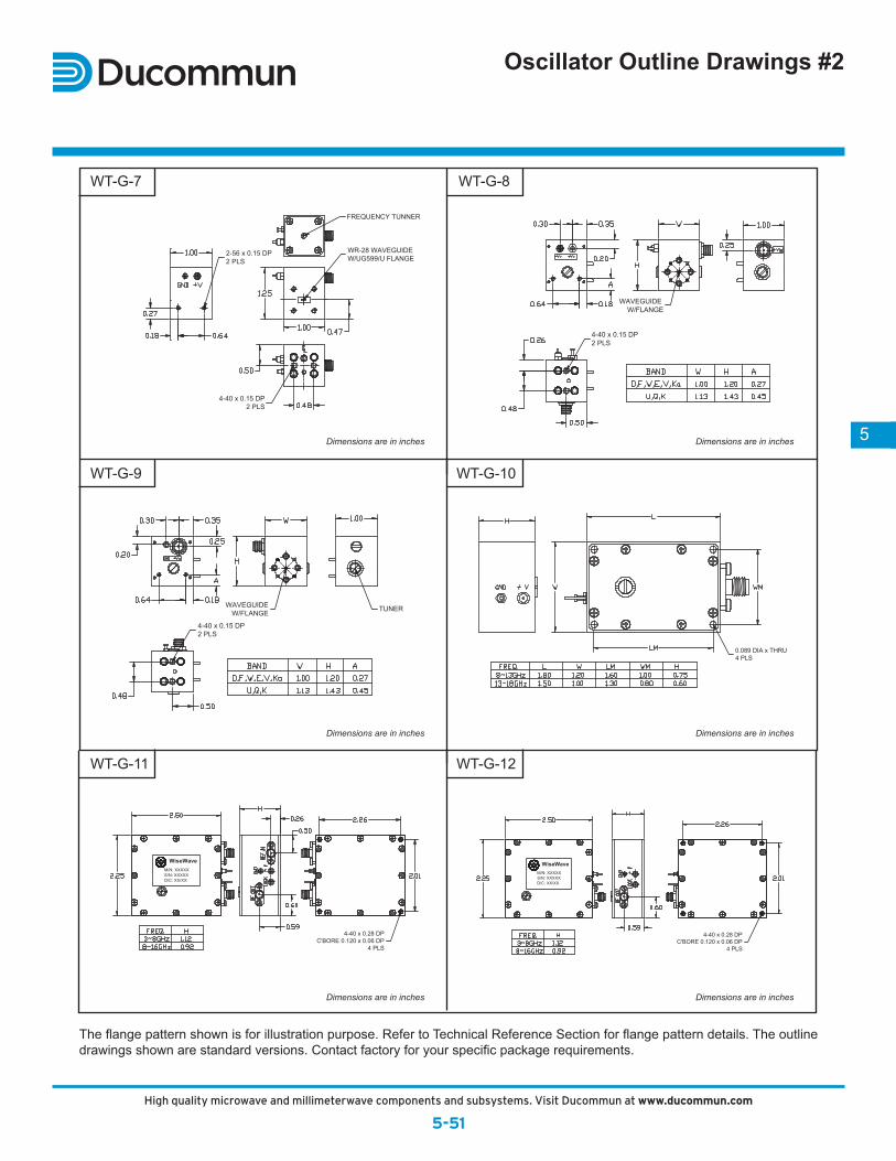
0.089 DIA x THRU4 PLS
WAVEGUIDEW/FLANGE TUNER
4-40 x 0.15 DP2 PLS
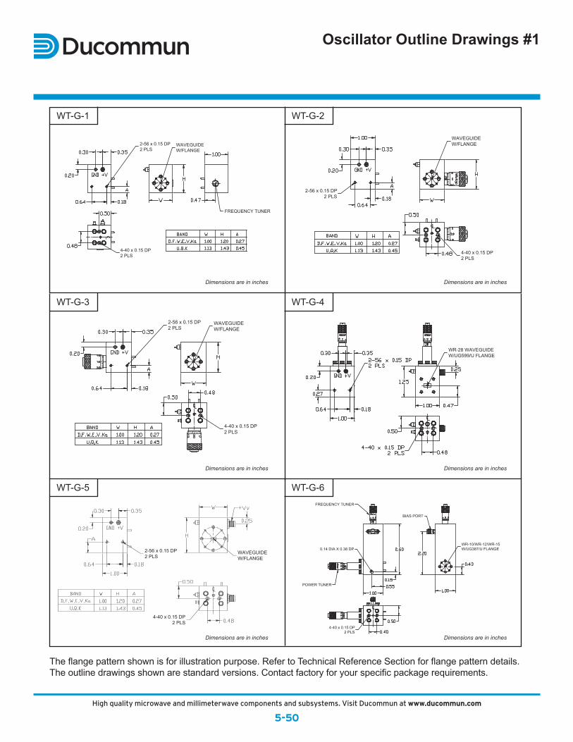
WAVEGUIDEW/FLANGE
4-40 x 0.15 DP2 PLS
2-56 x 0.15 DP2 PLS
WR-28 WAVEGUIDEW/UG599/U FLANGE
4-40 x 0.15 DP2 PLS
FREQUENCY TUNNER
Oscillator Outline Drawings #2
The flange pattern shown is for illustration purpose. Refer to Technical Reference Section for flange pattern details. The outline drawings shown are standard versions. Contact factory for your specific package requirements.
Dimensions are in inches
Dimensions are in inches
Dimensions are in inches
Dimensions are in inches
Dimensions are in inches
Dimensions are in inches
WT-G-7
WT-G-9
WT-G-11
WT-G-8
WT-G-10
WT-G-12
76155_DucMMWaveCat.indd 39 3/17/14 2:17 PM
5-50High quality microwave and millimeterwave components and subsystems. Visit Ducommun Technologies online at www.ducommun.com.
WAVEGUIDEW/FLANGE
2-56 x 0.15 DP2 PLS
4-40 x 0.15 DP2 PLS
WAVEGUIDEW/FLANGE
2-56 x 0.15 DP2 PLS
FREQUENCY TUNER
4-40 x 0.15 DP2 PLS
4-40 x 0.15 DP2 PLS
FREQUENCY TUNER
POWER TUNER
BIAS PORT
0.14 DIA X 0.38 DPWR-10/WR-12/WR-15W/UG387/U FLANGE
4-40 x 0.15 DP2 PLS
2-56 x 0.15 DP2 PLS
WAVEGUIDEW/FLANGE
WR-28 WAVEGUIDEW/UG599/U FLANGE
WAVEGUIDEW/FLANGE
2-56 x 0.15 DP2 PLS
4-40 x 0.15 DP2 PLS
Oscillator Outline Drawings #1
The flange pattern shown is for illustration purpose. Refer to Technical Reference Section for flange pattern details. The outline drawings shown are standard versions. Contact factory for your specific package requirements.
Dimensions are in inches
Dimensions are in inches
Dimensions are in inches
Dimensions are in inches
Dimensions are in inches
Dimensions are in inches
WT-G-1
WT-G-3
WT-G-5
WT-G-2
WT-G-4
WT-G-6
5-51High quality microwave and millimeterwave components and subsystems. Visit Ducommun Technologies online at www.ducommun.com.
5
4-40 x 0.28 DPC'BORE 0.120 x 0.06 DP
4 PLS
WiseWaveM/N: XXXXXS/N: XXXXXD/C: XX/XX
4-40 x 0.28 DPC'BORE 0.120 x 0.06 DP
4 PLS
WiseWaveM/N: XXXXXS/N: XXXXXD/C: XX/XX
0.089 DIA x THRU4 PLS
WAVEGUIDEW/FLANGE TUNER
4-40 x 0.15 DP2 PLS
WAVEGUIDEW/FLANGE
4-40 x 0.15 DP2 PLS
2-56 x 0.15 DP2 PLS
WR-28 WAVEGUIDEW/UG599/U FLANGE
4-40 x 0.15 DP2 PLS
FREQUENCY TUNNER
Oscillator Outline Drawings #2
The flange pattern shown is for illustration purpose. Refer to Technical Reference Section for flange pattern details. The outline drawings shown are standard versions. Contact factory for your specific package requirements.
Dimensions are in inches
Dimensions are in inches
Dimensions are in inches
Dimensions are in inches
Dimensions are in inches
Dimensions are in inches
WT-G-7
WT-G-9
WT-G-11
WT-G-8
WT-G-10
WT-G-12
High quality microwave and millimeterwave components and subsystems. Visit Ducommun at www.ducommun.com
5-50
76155_DucMMWaveCat.indd 50 3/17/14 2:17 PM
5-50High quality microwave and millimeterwave components and subsystems. Visit Ducommun Technologies online at www.ducommun.com.
WAVEGUIDEW/FLANGE
2-56 x 0.15 DP2 PLS
4-40 x 0.15 DP2 PLS
WAVEGUIDEW/FLANGE
2-56 x 0.15 DP2 PLS
FREQUENCY TUNER
4-40 x 0.15 DP2 PLS
4-40 x 0.15 DP2 PLS
FREQUENCY TUNER
POWER TUNER
BIAS PORT
0.14 DIA X 0.38 DPWR-10/WR-12/WR-15W/UG387/U FLANGE
4-40 x 0.15 DP2 PLS
2-56 x 0.15 DP2 PLS
WAVEGUIDEW/FLANGE
WR-28 WAVEGUIDEW/UG599/U FLANGE
WAVEGUIDEW/FLANGE
2-56 x 0.15 DP2 PLS
4-40 x 0.15 DP2 PLS
Oscillator Outline Drawings #1
The flange pattern shown is for illustration purpose. Refer to Technical Reference Section for flange pattern details. The outline drawings shown are standard versions. Contact factory for your specific package requirements.
Dimensions are in inches
Dimensions are in inches
Dimensions are in inches
Dimensions are in inches
Dimensions are in inches
Dimensions are in inches
WT-G-1
WT-G-3
WT-G-5
WT-G-2
WT-G-4
WT-G-6
5-51High quality microwave and millimeterwave components and subsystems. Visit Ducommun Technologies online at www.ducommun.com.
5
4-40 x 0.28 DPC'BORE 0.120 x 0.06 DP
4 PLS
WiseWaveM/N: XXXXXS/N: XXXXXD/C: XX/XX
4-40 x 0.28 DPC'BORE 0.120 x 0.06 DP
4 PLS
WiseWaveM/N: XXXXXS/N: XXXXXD/C: XX/XX
0.089 DIA x THRU4 PLS
WAVEGUIDEW/FLANGE TUNER
4-40 x 0.15 DP2 PLS
WAVEGUIDEW/FLANGE
4-40 x 0.15 DP2 PLS
2-56 x 0.15 DP2 PLS
WR-28 WAVEGUIDEW/UG599/U FLANGE
4-40 x 0.15 DP2 PLS
FREQUENCY TUNNER
Oscillator Outline Drawings #2
The flange pattern shown is for illustration purpose. Refer to Technical Reference Section for flange pattern details. The outline drawings shown are standard versions. Contact factory for your specific package requirements.
Dimensions are in inches
Dimensions are in inches
Dimensions are in inches
Dimensions are in inches
Dimensions are in inches
Dimensions are in inches
WT-G-7
WT-G-9
WT-G-11
WT-G-8
WT-G-10
WT-G-12
High quality microwave and millimeterwave components and subsystems. Visit Ducommun at www.ducommun.com
5-515-51High quality microwave and millimeterwave components and subsystems. Visit Ducommun Technologies online at www.ducommun.com.
5
4-40 x 0.28 DPC'BORE 0.120 x 0.06 DP
4 PLS
WiseWaveM/N: XXXXXS/N: XXXXXD/C: XX/XX
4-40 x 0.28 DPC'BORE 0.120 x 0.06 DP
4 PLS
WiseWaveM/N: XXXXXS/N: XXXXXD/C: XX/XX
0.089 DIA x THRU4 PLS
WAVEGUIDEW/FLANGE TUNER
4-40 x 0.15 DP2 PLS
WAVEGUIDEW/FLANGE
4-40 x 0.15 DP2 PLS
2-56 x 0.15 DP2 PLS
WR-28 WAVEGUIDEW/UG599/U FLANGE
4-40 x 0.15 DP2 PLS
FREQUENCY TUNNER
Oscillator Outline Drawings #2
The flange pattern shown is for illustration purpose. Refer to Technical Reference Section for flange pattern details. The outline drawings shown are standard versions. Contact factory for your specific package requirements.